

Page 1

ZUMNET-OD-GW-RF, ZUMMESH-OD-
KOM, ZUMMESH-OD-7P
Zūm® Outdoor Wireless Lighting System
Product Manual
Crestron Electronics, Inc.
Page 2

The original language version of this document is U.S. English.
All other languages are a translation of the original document.
Regulatory Model: M202217003, M202217004, M202217005, M202217006, and M202217007
Crestron product development software is licensed to Crestron dealers and Crestron Service Providers (CSPs) under a
limited nonexclusive, nontransferable Software Development Tools License Agreement. Crestron product operating
system software is licensed to Crestron dealers, CSPs, and end-users under a separate End-User License Agreement.
Both of these Agreements can be found on the Crestron website at www.crestron.com/legal/software_license_
agreement.
The product warranty can be found at www.crestron.com/warranty.
The specific patents that cover Crestron products are listed online at www.crestron.com/legal/patents.
Certain Crestron products contain open source software. For specific information, please visit
www.crestron.com/opensource.
Crestron, the Crestron logo, and Zūm are either trademarks or registered trademarks of Crestron Electronics, Inc. in the
United States and/or other countries. Other trademarks, registered trademarks, and trade names may be used in this
document to refer to either the entities claiming the marks and names or their products. Crestron disclaims any
proprietary interest in the marks and names of others. Crestron is not responsible for errors in typography or
photography.
©2023 Crestron Electronics, Inc.
Page 3

Contents
Overview 6
Features 7
ZUMNET-OD-GW-RF Features 8
ZUMMESH-OD-7P Features 10
ZUMMESH-OD-KOM Features 12
Specifications 15
ZUMNET-OD-GW-RF Specifications 16
Product Specifications 16
Dimension Drawings 18
ZUMMESH-OD-7P Specifications 19
Product Specifications 19
Dimension Drawings 21
ZUMMESH-OD-KOM Specifications 22
Product Specifications 22
Dimension Drawings 24
Installation 25
ZUMNET-OD-GW-RF Installation 26
In the Box 26
Install the ZUMNET-OD-GW-RF 26
ZUMMESH-OD-7P Installation 27
In the Box 27
Mount the ZUMMESH-OD-7P 27
ZUMMESH-OD-KOM Installation 28
In the Box 28
Install the ZUMMESH-OD-KOM 28
Configuration 30
Log In 31
Log into the ZUMNET-GW-RF 31
Log into the Wireless Router 31
Assign a Static IP Address for Gateway 32
Change the Administrator Password 33
Set Location and Timezone 34
Network Status 35
Recent Activities 36
Energy Monitor 37
View Energy Usage 37
Export Energy Usage 37
Upload a Map 38
Product Manual — Doc. 9376A Contents • iii
Page 4

Node Management 39
Add a Node to the Network 40
Remove a Node 41
Edit a Node Description 42
Group Management 43
Create and Rename Groups 44
Add a Node to a Group 46
Delete a Node from a Group 47
Delete a Group 48
LED Control 49
Control a Single LED 50
Control a Group of LEDs 51
Control all LEDs 52
Check Real-time Power Reading, Voltage, and Current 53
Sensor Management 54
Add a Sensor to a Node 55
Filter the List of Sensors 56
Enable or Disable a Sensor 57
Enable or Disable all Sensors 58
Set the Target to a Single LED 59
Set the Target to a Group of LEDs 60
Set the Target to All LEDs on the Gateway 61
Occupancy Sensor Specific Actions 62
Daylight Sensor Rules 63
Delete a Sensor 66
Scheduling 68
Add a Schedule 69
Schedule for a Single LED 70
Schedule for a Group of LEDs 71
Add Schedule for all the LEDs 72
Schedule the On or Off Time Set Control for an LED 73
Schedule the Brightness Control 74
Set a Schedule for an LED to Turn On at a Specific Time and Date 75
Set a Schedule for an LED to Turn On at Sunrise or Sunset 76
Set a Repeating Schedule for an LEDor Sensor 77
Set a Schedule for the Sensors 78
Delete a Schedule 79
Update Software 80
Resources 81
Crestron Support and Training 81
Programmer and Developer Resources 81
Product Certificates 81
iv • Contents Product Manual — Doc. 9376A
Page 5

v • Contents Product Manual — Doc. 9376A
Page 6

Overview
Crestron Zūm® Outdoor is a distributed lighting control system. The Zūm Outdoor system provides
control of up to 500 nodes and allows seamless integration of third-party occupancy sensors and
photocells.
These Zūm Outdoor devices are available:
l
ZUMNET-OD-GW-RF
l
ZUMMESH-OD-7P-277V
l
ZUMMESH-OD-7P-277V-DLS
l
ZUMMESH-OD-7P-480V
l
ZUMMESH-OD-7P-480V-DLS
l
ZUMMESH-OD-KOM-277V
l
ZUMMESH-OD-KOM-277V-SMA
l
ZUMMESH-OD-KOM-480V
l
ZUMMESH-OD-KOM-480V-SMA
Product Manual — Doc. 9376A ZUMNET-OD-GW-RF, ZUMMESH-OD-KOM, ZUMMESH-OD-7P • 6
Page 7

Features
Refer to the following sections for information on the features provided by various Zūm® Outdoor
system models.
This section provides the following information:
•ZUMNET-OD-GW-RF Features
•ZUMMESH-OD-7P Features
•ZUMMESH-OD-KOM Features
7 • ZUMNET-OD-GW-RF, ZUMMESH-OD-KOM, ZUMMESH-OD-7P Product Manual — Doc. 9376A
Page 8
ZUMNET-OD-GW-RF Features
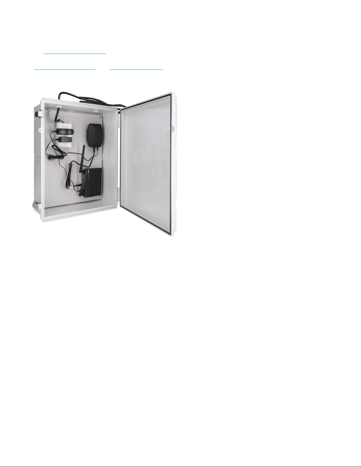
The ZUMNET-OD-GW-RF is a 2-way RF Wireless Gateway designed for use with Crestron® Zūm
Outdoor wireless devices. A single ZUMNET-OD-GW-RF can manage up to 500 ZUMMESH-OD nodes
(ZUMMESH-OD-KOM and ZUMMESH-OD-7P both sold separately). The ZUMNET-OD-GW-RF uses a
web-based application to manage and control the light fixtures in addition to scheduling dimming,
grouping, sensor input capabilities, remote monitoring, and management.
Key features include:
l
Uses Zūm® Outdoor self-forming and self-restoring wireless mesh network
l
Remote control, scheduling, and sensor configuration
l
Reliable and encrypted communication
l
Supports over-the-air (OTA) firmware updates
l
Flexible event-based scheduling system
l
Lighting fixture fault monitoring and reporting
l
Connects up to 500 nodes
l
Includes wireless router for communications with a local network
l
Provides real-time status updates for each light fixture, including energy usage, light status,
sensor analysis, and more
l
Gateway hosts Crestron Web UI for system control and management
l
Gateway mounts in the enclosure
Zum® Outdoor Wireless Mesh Network
Zūm Outdoor wireless mesh technology provides peer-to-peer RF communications without the need for
physical control wiring, hubs, or gateways. Zūm mesh outdoor devices act as routing nodes to relay
Product Manual — Doc. 9376A ZUMNET-OD-GW-RF, ZUMMESH-OD-KOM, ZUMMESH-OD-7P • 8
Page 9

wireless commands between them without disruption. Adding Zūm mesh devices to a space increases
the range and stability of the peer-to-peer mesh network by providing multiple redundant signal paths.
Each Zūm mesh device auto negotiates its RF channel to provide robust communication.
Self-Forming and Self-Restoring Wireless Mesh Network
Zūm Outdoor wireless mesh technology auto-searches and establishes connections in a network. If a
wireless connection in the network is not working, the Zūm mesh device disables the path and reroutes
the data to ensure seamless communication. Once the device restores, the Zūm device automatically
rejoins the network.
Flexible Event-based Scheduling System
Event-based scheduling allows the creation of quick and flexible lighting schedules. The series of lights
are manageable for better real estate planning.
Lighting Fixture Fault Monitoring and Reporting
Fault monitoring and reporting applications help to for control, monitoring, commissioning, and
programming of individual or groups of lights in a network to prevent issues.
Web User Interface for System Control and Management
This gateway hosts the configuration screens for the system control and management. The system can
schedule events and adjust the lighting based on feedback from daylight and motion sensors.
OTA Firmware Updates
Over-the-air (OTA) firmware updates reduce operational costs by providing an efficient update process
that does not require direct access to the device. Updates are made remotely and deployed
incrementally to make sure that the system remains functional.
9 • ZUMNET-OD-GW-RF, ZUMMESH-OD-KOM, ZUMMESH-OD-7P Product Manual — Doc. 9376A
Page 10
ZUMMESH-OD-7P Features
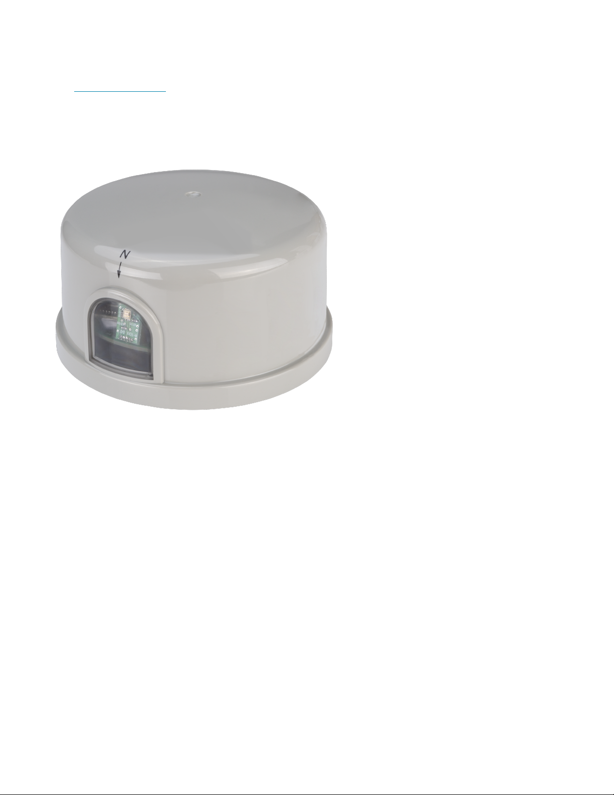
The ZUMMESH-OD-7P is a wireless network-connected lighting controller with dimming, energymetering, remote monitoring and management, and sensor input capabilities. A single ZUMMESH-OD7P has sensor inputs for both occupancy and daylight sensors. The nodes provide 12VDC power to the
sensors. It has 4kV fault tolerance and control persistency. The status and health of the light fixtures are
continuously monitored. The 7-pin (ANSI 136-41) dimming (NEMA) receptacles aid in a quick and simple
installation.
Key features include:
l
Uses Zūm® Outdoor self-forming and self-restoring wireless mesh network
l
Remote control, scheduling, and sensor configuration
l
In-node scheduling: NEMA custom schedules are programmed to the node, with RTC (Remote
Time Clock) built into each controller, schedules run with or without wireless connectivity
l
Built-in power monitoring
l
Sensor inputs for motion or light sensing
l
Linear continuous dimming - high resolution dimming (100+ steps)
l
Optional built-in photocell to report daylight levels (-DLS models only)
l
Reliable and encrypted communication
l
Supports over-the-air (OTA) firmware updates
l
Flexible event-based scheduling system
l
Lighting fixture fault monitoring and reporting
Product Manual — Doc. 9376A ZUMNET-OD-GW-RF, ZUMMESH-OD-KOM, ZUMMESH-OD-7P • 10
Page 11

Zum® Outdoor Wireless Mesh Network
Zūm Outdoor wireless mesh technology provides peer-to-peer RF communications without the need for
physical control wiring, hubs, or gateways. Zūm mesh outdoor devices act as routing nodes to relay
wireless commands between them without disruption. Adding Zūm mesh devices to a space increases
the range and stability of the peer-to-peer mesh network by providing multiple redundant signal paths.
Each Zūm mesh device auto negotiates its RF channel to provide robust communication.
Self-Forming and Self-Restoring Wireless Mesh Network
Zūm Outdoor wireless mesh technology auto-searches and establishes connections in a network. If a
wireless connection in the network is not working, the Zūm mesh device disables the path and reroutes
the data to ensure seamless communication. Once the device restores, the Zūm device automatically
rejoins the network.
Built-in Power Monitoring
Power monitoring tracks the real time energy usage of each node in the system to help control energy
costs. By analyzing real data, organizations can make more educated decisions regarding the energy
usage.
Daylight and Motion Sensor Inputs
Daylight and Motion Sensor inputs enable the use of hard-wired occupancy and daylight sensors with a
Zūm commercial lighting system. The sensor enables the use of ultrasonic and dual-technology type
sensors for outdoors. One or more motion-detecting sensors can be connected and configured to
operate in either occupancy or vacancy-only mode. A photocell (not supplied) can be connected to
support daylight harvesting. A built-in photocell (-DLS models only) is included to report daylight levels.
Linear Continuous Dimming – High-Resolution Dimming (100+ steps)
Linear continuous dimming provides one channel of dimming for commercial lighting applications.
Supports a continuous dimming range of 1% to 100%.
Flexible Event-based Scheduling System
Event-based scheduling allows the creation of quick and flexible lighting schedules. The series of lights
are manageable for better real estate planning.
Lighting Fixture Fault Monitoring and Reporting
Fault monitoring and reporting applications help to for control, monitoring, commissioning, and
programming of individual or groups of lights in a network to prevent issues.
OTA Firmware Updates
Over-the-air (OTA) firmware updates reduce operational costs by providing an efficient update process
that does not require direct access to the device. Updates are made remotely and deployed
incrementally to make sure that the system remains functional.
11 • ZUMNET-OD-GW-RF, ZUMMESH-OD-KOM, ZUMMESH-OD-7P Product Manual — Doc. 9376A
Page 12

ZUMMESH-OD-KOM Features
The ZUMMESH-OD-KOM is a wireless network-connected lighting controller with dimming, switching,
energy metering, remote monitoring and management, and sensor input capabilities. The ZUMMESHOD-KOM has sensor inputs for both occupancy and daylight sensors and can provide 12VDC power to
the sensors. It has 4kV fault tolerance and control persistency. The status and health of the light fixtures
are continuously monitored. The compact design with a waterproof feature enables mounting inside or
outside a light fixture or pole for a quick and simple installation.
Key features include:
l
Uses Zūm® Outdoor self-forming and self-restoring wireless mesh network
l
Remote control, scheduling, and sensor configuration
l
In-node scheduling: NEMA custom schedules are programmed to the node, with RTC (Remote
Time Clock) built into each controller, schedules run with or without wireless connectivity
l
Built-in power monitoring
l
Sensor inputs for motion and light sensing with 12VDC output for sensors
l
Two 0-10V dimming outputs
l
Linear continuous dimming - high resolution dimming (100+ steps)
l
Remote programmable high-end trim
l
External antenna connection for installation locations that impede wireless signal (-SMA models
only, antenna not included)
l
Reliable and encrypted communication
l
Supports over-the-air (OTA) firmware updates
l
Flexible event-based scheduling system
l
Lighting fixture fault monitoring and reporting
Product Manual — Doc. 9376A ZUMNET-OD-GW-RF, ZUMMESH-OD-KOM, ZUMMESH-OD-7P • 12
Page 13

Zum® Outdoor Wireless Mesh Network
Zūm Outdoor wireless mesh technology provides peer-to-peer RF communications without the need for
physical control wiring, hubs, or gateways. Zūm mesh outdoor devices act as routing nodes to relay
wireless commands between them without disruption. Adding Zūm mesh devices to a space increases
the range and stability of the peer-to-peer mesh network by providing multiple redundant signal paths.
Each Zūm mesh device auto negotiates its RF channel to provide robust communication.
Self-Forming and Self-Restoring Wireless Mesh Network
Zūm Outdoor wireless mesh technology auto-searches and establishes connections in a network. If a
wireless connection in the network is not working, the Zūm mesh device disables the path and reroutes
the data to ensure seamless communication. Once the device restores, the Zūm device automatically
rejoins the network.
Built-in Power Monitoring
Power monitoring tracks the real time energy usage of each node in the system to help control energy
costs. By analyzing real data, organizations can make more educated decisions regarding the energy
usage.
Daylight and Motion Sensor Inputs
Daylight and Motion Sensor inputs enable the use of hard-wired occupancy and daylight sensors with a
Zūm commercial lighting system. The sensor enables the use of ultrasonic and dual-technology type
sensors for outdoors. One or more motion-detecting sensors can be connected and configured to
operate in either occupancy or vacancy-only mode. A photocell (not supplied) can be connected to
support daylight harvesting.
Linear Continuous Dimming – High-Resolution Dimming (100+ steps)
Linear continuous dimming provides one channel of dimming for commercial lighting applications.
Supports a continuous dimming range of 1% to 100%.
Remote Programmable High-End Trim
Provides high-end trim for one or multiple zones, which helps with energy optimization.
Optional External Antenna
Connect an external antenna (SMA models only, antenna not included) to improve radio coverage in the
Zūm outdoor system when the node is mounted inside an enclosure or the signal is blocked by an
obstruction.
Flexible Event-based Scheduling System
Event-based scheduling allows the creation of quick and flexible lighting schedules. The series of lights
are manageable for better real estate planning.
Lighting Fixture Fault Monitoring and Reporting
Fault monitoring and reporting applications help to for control, monitoring, commissioning, and
programming of individual or groups of lights in a network to prevent issues.
13 • ZUMNET-OD-GW-RF, ZUMMESH-OD-KOM, ZUMMESH-OD-7P Product Manual — Doc. 9376A
Page 14

OTA Firmware Updates
Over-the-air (OTA) firmware updates reduce operational costs by providing an efficient update process
that does not require direct access to the device. Updates are made remotely and deployed
incrementally to make sure that the system remains functional.
Product Manual — Doc. 9376A ZUMNET-OD-GW-RF, ZUMMESH-OD-KOM, ZUMMESH-OD-7P • 14
Page 15

Specifications
Refer to the following sections for more information on the specifications for various Zum Outdoor
Wireless Lighting system.
This section provides the following information:
•ZUMNET-OD-GW-RF Specifications
•ZUMMESH-OD-7P Specifications
•ZUMMESH-OD-KOM Specifications
15 • ZUMNET-OD-GW-RF, ZUMMESH-OD-KOM, ZUMMESH-OD-7P Product Manual — Doc. 9376A
Page 16

ZUMNET-OD-GW-RF Specifications
Product specifications for the ZUMNET-OD-GW-RF are provided below.
Product Specifications
Power Requirements
Voltage 100-240VAC
Wireless Communications
RF Transceiver Zum Outdoor wireless, 2-way RF, 2.4 Ghz
Topology Mesh topology
Device Type Gateway;
Coordinates the mesh network, routes data to nodes, and communicates with
network
Coverage Range (typical) Gateway to Node: 2,000ft (610m);
Node to Node: 2,000ft (610m)
Maximum of 10 hops on the mesh network between the Gateway and the last node
Wireless N Router IEEE 802.11a, IEEE 802.11b, IEEE 802.11g, WiFi 4 (802.11n), IPv4, IPv6
Wired Communications
Router Ethernet (IPv4, IPv6);
Router mode, Repeater mode, and AP mode
Gateway Ethernet and USB
Connections - Router
WAN (1) 8-pin RJ-45, female;
100Base-TX Ethernet port;
Connects to existing network modem or switch
LAN (4) 8-pin RJ-45, female;
100Base-TX Ethernet port;
Connects to Gateway
DC IN (1) DC power connector;
12VDC power input, 0.5A max;
Power supply included
Connections - Gateway
ETHERNET (1) 8-pin RJ-45, female;
100Base-TX Ethernet port;
Connects to Router
USB (1) USB, female;
Connects to PC for configuration without an Ethernet connection;
Provides power when there is no power connection
Product Manual — Doc. 9376A ZUMNET-OD-GW-RF, ZUMMESH-OD-KOM, ZUMMESH-OD-7P • 16
Page 17

Power (1) DC power connector;
5VDC power input;
Power supply included
Environmental
Temperature -40° to 122° F (-40° to 50° C)
Humidity 5% to 95% RH (noncondensing)
Construction
Material Plastic, IP67 rated
Mounting Surface mount
Dimensions
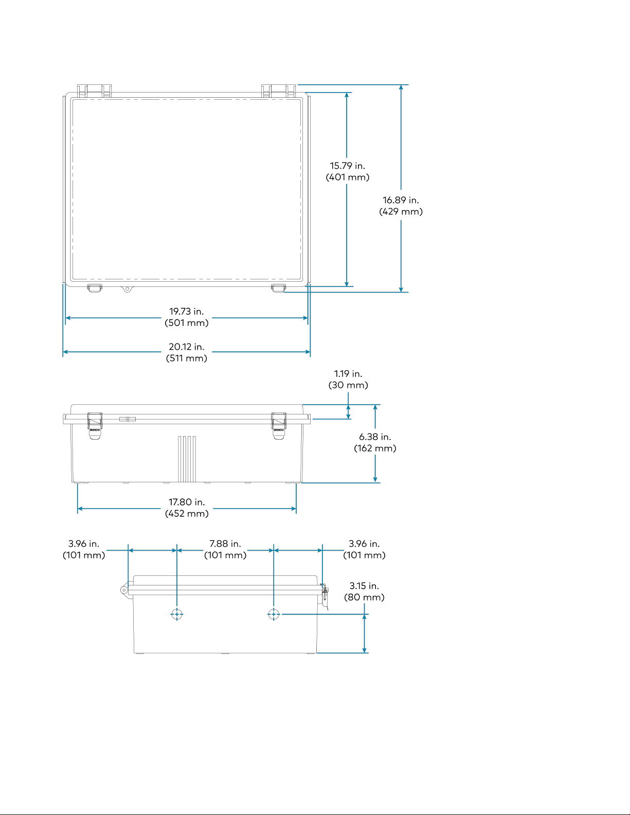
Height 20.1 in. (511 mm)
Width 16.9 in. (429 mm)
Depth 6.3 in. (160 mm)
Regulatory Model: M202217003, M202217005, and M202217007
FCC, DLC
To search for product certificates, refer to support.crestron.com/app/certificates.
17 • ZUMNET-OD-GW-RF, ZUMMESH-OD-KOM, ZUMMESH-OD-7P Product Manual — Doc. 9376A
Page 18
Dimension Drawings
Product Manual — Doc. 9376A ZUMNET-OD-GW-RF, ZUMMESH-OD-KOM, ZUMMESH-OD-7P • 18
Page 19

ZUMMESH-OD-7P Specifications
Product specifications for the ZUMMESH-OD-7P are provided below.
Product Specifications
Power Requirements
Voltage 277VAC Models: 120-277VAC (+/- 10%)
480VAC Models: 347-480VAC (+/- 10%)
Load Control
Dimming Output (1) 0-10V, 20mA
Max Load Current 277VAC Models: 10A
480VAC Models: 5A
Surge Protection
(Controller only)
Wireless Communications
RF Transceiver Zum Outdoor wireless, 2-way RF, 2.4 Ghz
Topology Mesh topology
Device Type Node;
Coverage Range (typical) Gateway to Node: 2,000ft (610m);
4kV (Lighting load protection provided by lighting load's circuit breaker)
Routes data between nodes and gateway
Node to Node: 2,000ft (610m)
Maximum of 10 hops on the mesh network between the Gateway and the last node
Connections
7-Pin Connector (1) 7-pin NEMA connector;
Connects to ANSI 136-41 receptacle;
Load: Load, Red wire;
L: Line, Black wire;
N: Neutral, White wire;
Pin 1: Dimming -, Gray wire;
Pin 2:Dimming +, Violet wire;
Pin 3: Sensor input, Orange wire;
Pin 4: Sensor Input, Brown wire
Environmental
Temperature -40° to 122° F (-40° to 50° C)
Humidity 5% to 95% RH (noncondensing)
Construction
Material Plastic, IP67 rated
Mounting NEMA-rated 7-pin
19 • ZUMNET-OD-GW-RF, ZUMMESH-OD-KOM, ZUMMESH-OD-7P Product Manual — Doc. 9376A
Page 20

Dimensions
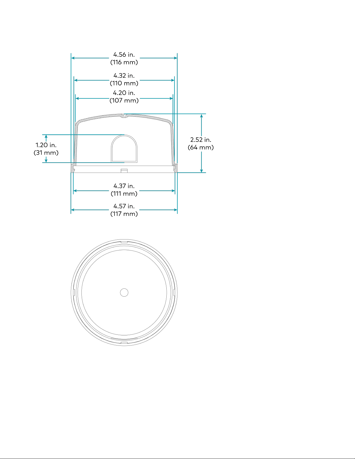
Height 2.5in. (64mm)
Width 4.6in. (116mm)
Depth 4.6in. (116mm)
Weight
0.835 lb (0.378 kg)
Compliance
Regulatory Model: M202217004
FCC, DLC
To search for product certificates, refer to support.crestron.com/app/certificates.
Product Manual — Doc. 9376A ZUMNET-OD-GW-RF, ZUMMESH-OD-KOM, ZUMMESH-OD-7P • 20
Page 21
Dimension Drawings
21 • ZUMNET-OD-GW-RF, ZUMMESH-OD-KOM, ZUMMESH-OD-7P Product Manual — Doc. 9376A
Page 22

ZUMMESH-OD-KOM Specifications
Product specifications for the ZUMMESH-OD-KOM are provided below.
Product Specifications
Power Requirements
Voltage 277VAC Models: 120-277VAC (+/- 10%)
480VAC Models: 347-480VAC (+/- 10%)
Load Control
Dimming Output (1) 0-10V, 20mA
Max Load Current 277VAC Models: 10A
480VAC Models: 5A
Surge Protection
(Controller only)
Wireless Communications
RF Transceiver Zum Outdoor wireless, 2-way RF, 2.4 Ghz
Topology Mesh topology
Device Type Node;
Coverage Range (typical) Gateway to Node: 2,000ft (610m);
4kV (Lighting load protection provided by lighting load's circuit breaker)
Routes data between nodes and gateway
Node to Node: 2,000ft (610m)
Maximum of 10 hops on the mesh network between the Gateway and the last node
Connections
Control (1) 8-wire cable for load control, flying lead, class 2;
22 AWG (0.34 mm2);
White: 12V output;
Red: 3.3Voutput;
Brown: Analog control 10V, channel 1;
Orange: Analog control 10V, channel 2;
Black: Analog control ground;
Yellow: Light sensor input;
Blue: Motion sensor input;
Green: Sensor input ground
Power (1) 3-wire cable for power, flying lead, class 1;
18 AWG (0.75 mm2);
Black: Hot, line power input;
White: Neutral from line power, to LED neutral;
Red: Switched power output, to LED power
Antenna (1) Connection for antenna
(-SMA models only, antenna not included)
Environmental
Product Manual — Doc. 9376A ZUMNET-OD-GW-RF, ZUMMESH-OD-KOM, ZUMMESH-OD-7P • 22
Page 23

Temperature -40° to 122° F (-40° to 50° C)
Humidity 5% to 95% RH (noncondensing)
Construction
Material Plastic, IP67 rated
Mounting Pole surface mounted 1/2 in. conduit knock-out mount
Dimensions
Height 1.70 in. (43 mm)
Width 6.20 in. (158 mm)
Depth 3.6 in. (92 mm)
Weight
1.016 lb (0.460 kg)
Regulatory Model: M202217006
FCC, DLC
To search for product certificates, refer to support.crestron.com/app/certificates.
23 • ZUMNET-OD-GW-RF, ZUMMESH-OD-KOM, ZUMMESH-OD-7P Product Manual — Doc. 9376A
Page 24
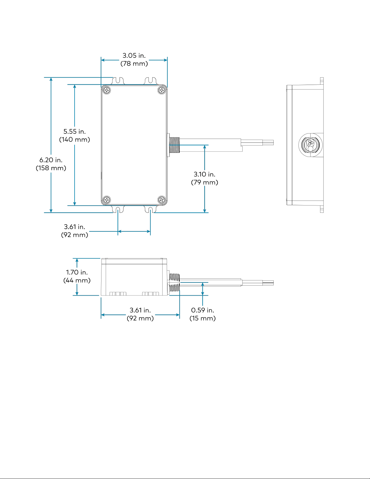
Dimension Drawings
Product Manual — Doc. 9376A ZUMNET-OD-GW-RF, ZUMMESH-OD-KOM, ZUMMESH-OD-7P • 24
Page 25

Installation
Refer to the following sections for information on how to install and set up Zum Outdoor Wireless
lighting system.
This section provides the following information:
•ZUMNET-OD-GW-RF Installation
•ZUMMESH-OD-7P Installation
•ZUMMESH-OD-KOM Installation
25 • ZUMNET-OD-GW-RF, ZUMMESH-OD-KOM, ZUMMESH-OD-7P Product Manual — Doc. 9376A
Page 26

ZUMNET-OD-GW-RF Installation
Use the following procedures to install the ZUMNET-OD-GW-RF.
In the Box
Qty. Description
1 ZUMNET-OD-GW-RF, Centralized Controller and Wireless Gateway, 100-240VAC, Zūm®
Outdoor Wireless Communications, Mounted in exterior rated enclosure
Install the ZUMNET-OD-GW-RF
The ZUMNET-OD-GW-RF may be mounted to a pole or a flat surface.
Pole Placement
To mount the ZUMNET-OD-GW-RF on a pole, a third-party pole mount kit (not supplied) is required
(such as an L-COM® HGZ-PMT13 or equivalent).
NOTE: Select a location that provides direct line of sight between the ZUMNET-OD-GW-RF and at
least two other lighting controllers in the network. The ZUMNET-OD-GW-RF must be mounted
vertically with the conduit coming out of the bottom of the unit. The wireless signals may get
obstructed if the ZUMNET-OD-GW-RF is mounted horizontally.
To mount ZUMNET-OD-GW-RF on a pole:
1. Mount the ZUMNET-OD-GW-RF to a pole using compatible L-com pole straps.
2. Fix the ZUMNET-OD-GW-RF with the straps to the pole.
Surface Placement
To place ZUMNET-OD-GW-RF on a surface:
1. Use four 0.25 in. diameter screws that fit the 0.310 in. diameter mounting holes and support 50
lbs. of weight.
2. Attach the ZUMNET-OD-GW-RF to the surface vertically with the screws provided.
NOTE: Once the ZUMNET-OD-GW-RF is mounted, a licensed electrician should connect power to
the ZUMNET-OD-GW-RF wiring compartment according to national, state, and local electrical
codes and requirements. The three connection points in the wiring compartment are Black for Line,
White for Neutral, and Green for Ground.
Product Manual — Doc. 9376A ZUMNET-OD-GW-RF, ZUMMESH-OD-KOM, ZUMMESH-OD-7P • 26
Page 27
ZUMMESH-OD-7P Installation
Use the following procedure to install the ZUMMESH-OD-7P.
NOTE: Each light fixture requires one ZUMMESH-OD-7P or ZUMMESH-OD-KOM.
In the Box
Qty. Description
1 ZUMMESH-OD-7P, 0-10V Dimmer, 1 Feed, Zūm® Outdoor Wireless Communications – 7-Pin
NEMA Mount
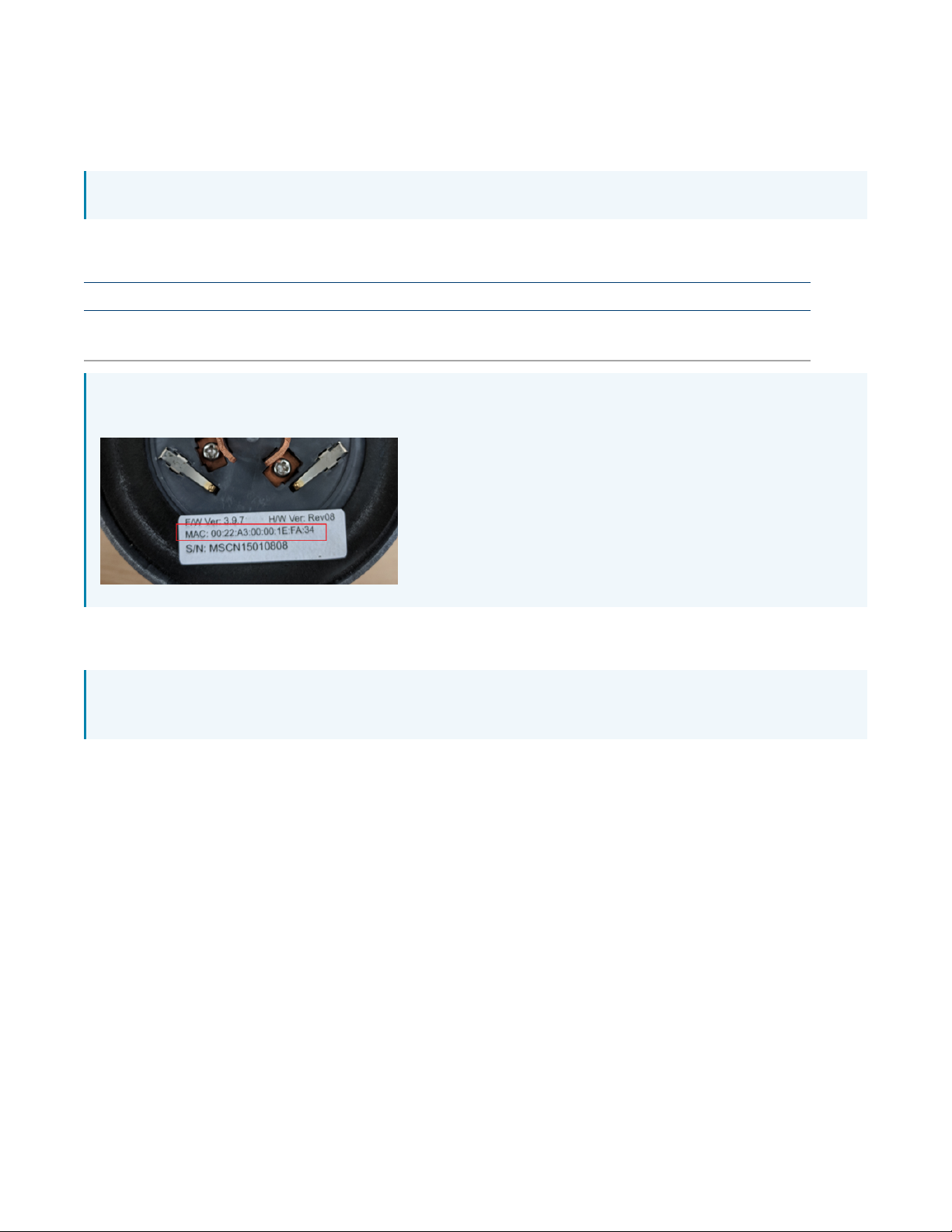
NOTE: Record the MAC addresses prior installing the node. The MAC address is on a label on the
bottom of the node.
Mount the ZUMMESH-OD-7P
NOTE: The fixture must have an ANSI C136.41 receptacle installed and wired before the ZUMMESHOD-7P can be installed.
To mount the ZUMMESH-OD-7P to an ANSI C136.41 receptacle:
1. Make sure the wide blade connector of the ZUMMESH-OD-7P matches the wide blade position of
the receptacle.
2. Twist the ZUMMESH-OD-7P node clockwise until it locks firmly to the ANSI C136.41 receptacle.
27 • ZUMNET-OD-GW-RF, ZUMMESH-OD-KOM, ZUMMESH-OD-7P Product Manual — Doc. 9376A
Page 28
ZUMMESH-OD-KOM Installation
Use the following procedure to install the ZUMMESH-OD-KOM.
NOTE: Each light fixture requires one ZUMMESH-OD-7P or ZUMMESH-OD-KOM.
In the Box
Qty. Description
1 ZUMMESH-OD-KOM, 0-10V Dimmer, 2 Channels, 1 Feed, Zūm® Outdoor Wireless
Communications, Universal – Knock out mount
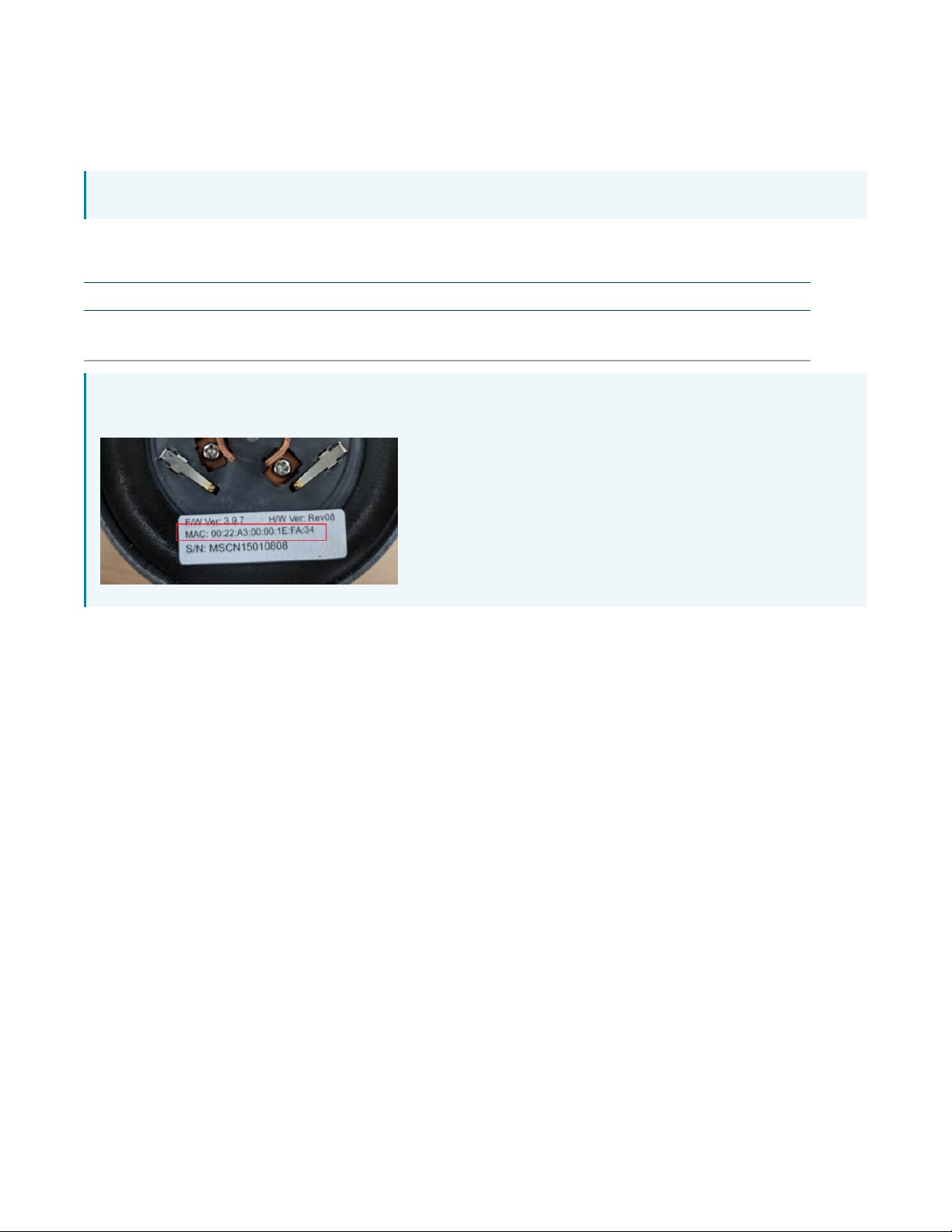
NOTE: Record the MAC addresses prior installing the node. The MAC address is on a label on the
bottom of the node.
Install the ZUMMESH-OD-KOM
To install the ZUMMESH-OD-KOM:
Make Power Connections
1. Connect the electrical service black wire to the line input on the ZUMMESH-OD-KOM.
2. Connect the black wire of the LED fixture to the load output on the ZUMMESH-OD-KOM.
3. Connect the electrical service white wire (neutral) to the neutral input on the ZUMMESH-ODKOM.
4. Connect the white wire (neutral) from the LED fixture to the electrical service white wire
(neutral).
Make Dimmer Connections
1. Connect the DIM- wire on the LED fixture to the COM (black) on the ZUMMESH-OD-KOM.
2. Connect the DIM+ wire on the LED fixture to the DIM OUT1 on the ZUMMESH-OD-KOM.
3. Switch power on to the fixture. The light should turn on.
Product Manual — Doc. 9376A ZUMNET-OD-GW-RF, ZUMMESH-OD-KOM, ZUMMESH-OD-7P • 28
Page 29

NOTE: When switched on, lamps should turn on to full brightness, with approximately 10VDC signal
on the DIM+ wire using the DIM- wire as reference.
Make Sensor Connections (Optional)
1. Connect the ZUMMESH-OD-KOM Light Sensor IN to the light sensor output and Motion Sensor
IN to the motion sensor output (if applicable).
2. Connect the ZUMMESH-OD-KOM COM (green) signal to the common (ground) connection on the
sensor(s).
3. Connect the ZUMMESH-OD-KOM +12V OUT output to the power input on the sensor(s).
NOTE: The ZUMMESH-OD-KOM output must be connected to the power input of the sensor.
4. Connect the ZUMMESH-OD-KOM input to the Common (ground) signal on the sensor(s).
29 • ZUMNET-OD-GW-RF, ZUMMESH-OD-KOM, ZUMMESH-OD-7P Product Manual — Doc. 9376A
Page 30

Configuration
Refer to the following sections for information on how to set up an IP address, administrator account,
and how to configure timezone and location.
This section provides the following information:
•Log In
•Assign a Static IP Address for Gateway
•Change the Administrator Password
•Set Location and Timezone
•Network Status
•Recent Activities
•Energy Monitor
•Upload a Map
•Node Management
•Group Management
•LED Control
•Sensor Management
•Scheduling
•Update Software
Product Manual — Doc. 9376A ZUMNET-OD-GW-RF, ZUMMESH-OD-KOM, ZUMMESH-OD-7P • 30
Page 31
Log In
Use the following procedures to log into the ZUMNET-GW-RF and wireless router.
Log into the ZUMNET-GW-RF
To log into the ZUMNET-GW-RF:
1. Enter the IPaddress of the gateway into a web browser.
2. Enter the user name and password for the gateway. The default user name for the ZUMNET-GWRF is admin and the password is meshnetwork.
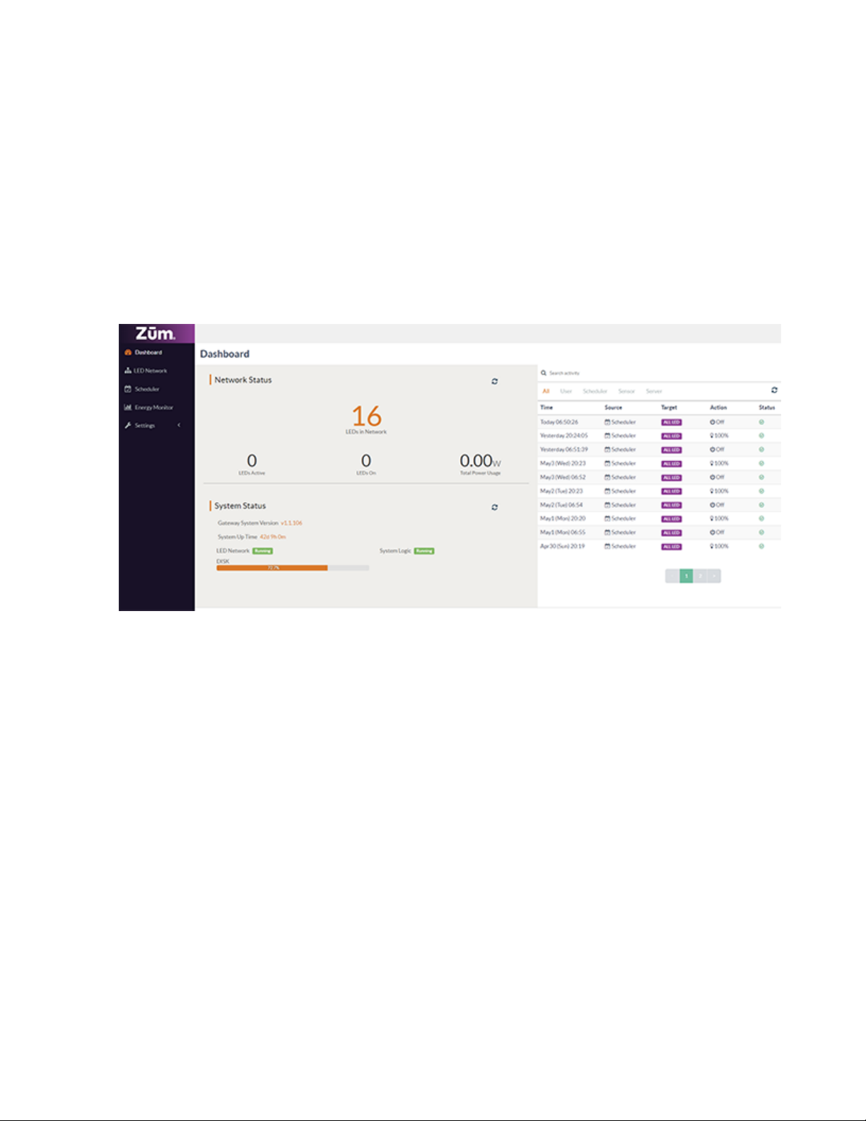
3. The Dashboard screen is displayed.
Log into the Wireless Router
To log into the wireless router:
1. Enter the IPaddress of the router into a web browser.
2. Enter the user name and password for the gatewa. The default user name for the gateway is
admin and the password is meshnetwork.
31 • ZUMNET-OD-GW-RF, ZUMMESH-OD-KOM, ZUMMESH-OD-7P Product Manual — Doc. 9376A
Page 32
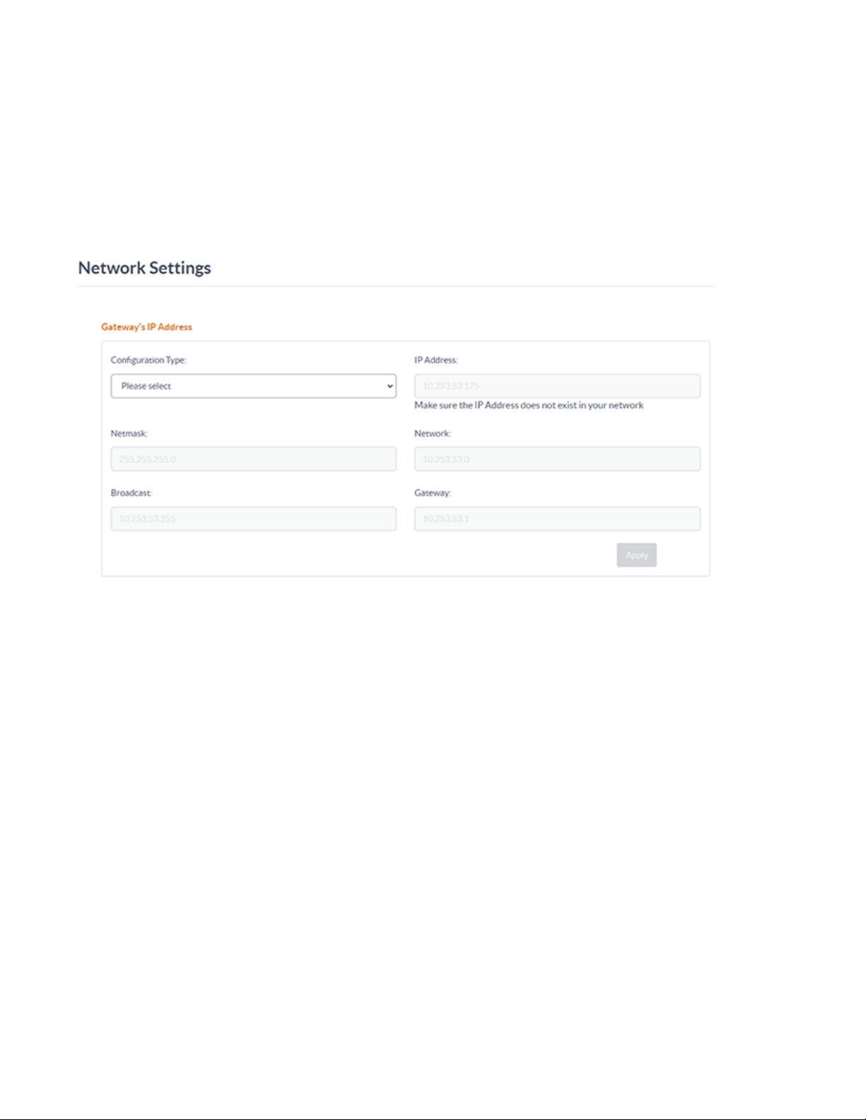
Assign a Static IP Address for Gateway
To assign a static IP address for the gateway:
1. Go to Settings>Network Settings.
2. Select Static under the Configuration Type drop-down menu.
3. Enter the static IP address in the IP Address text box.
4. Select Apply.
Product Manual — Doc. 9376A ZUMNET-OD-GW-RF, ZUMMESH-OD-KOM, ZUMMESH-OD-7P • 32
Page 33
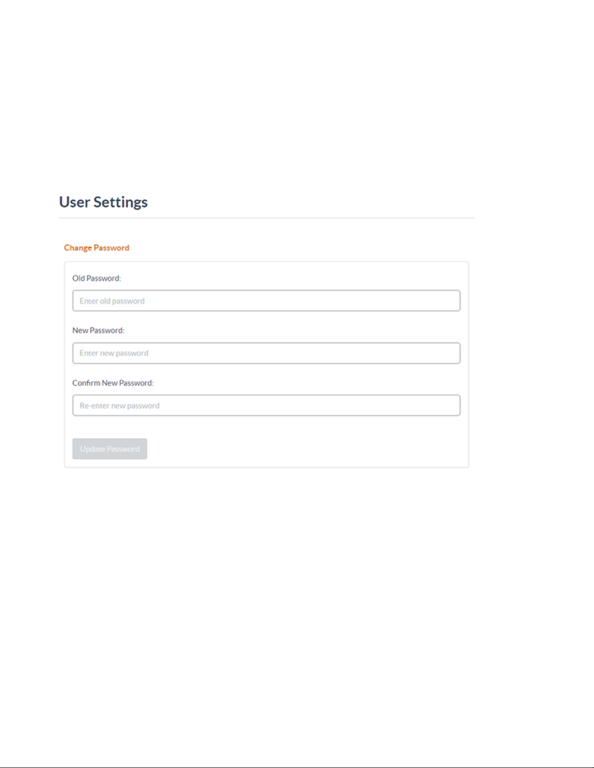
Change the Administrator Password
To change the administrator password:
1. Go to Settings > User Settings.
2. Type the current password in the Old Password box.
3. Type the desired password in the New Password box and then type it again in the Confirm New
Password box to confirm.
4. Select Update Password.
33 • ZUMNET-OD-GW-RF, ZUMMESH-OD-KOM, ZUMMESH-OD-7P Product Manual — Doc. 9376A
Page 34
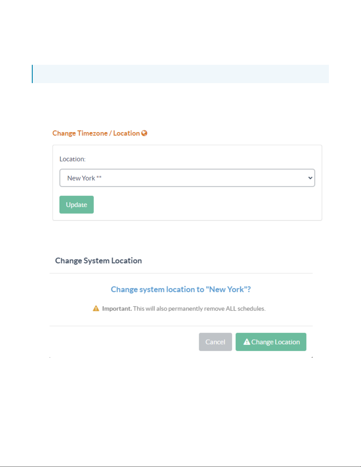
Set Location and Timezone
To set a location and timezone:
NOTE: All schedules are removed when changing the location setting.
1. Go to Settings > Gateway Settings.
2. Choose the city closest to, and in the same timezone as, the current location of the LED system
using the Location drop-down menu.
3. Select Update.
4. The Change System Location confirmation dialog-box appears. Select Change Location to
confirm the change in location and timezone.
Product Manual — Doc. 9376A ZUMNET-OD-GW-RF, ZUMMESH-OD-KOM, ZUMMESH-OD-7P • 34
Page 35
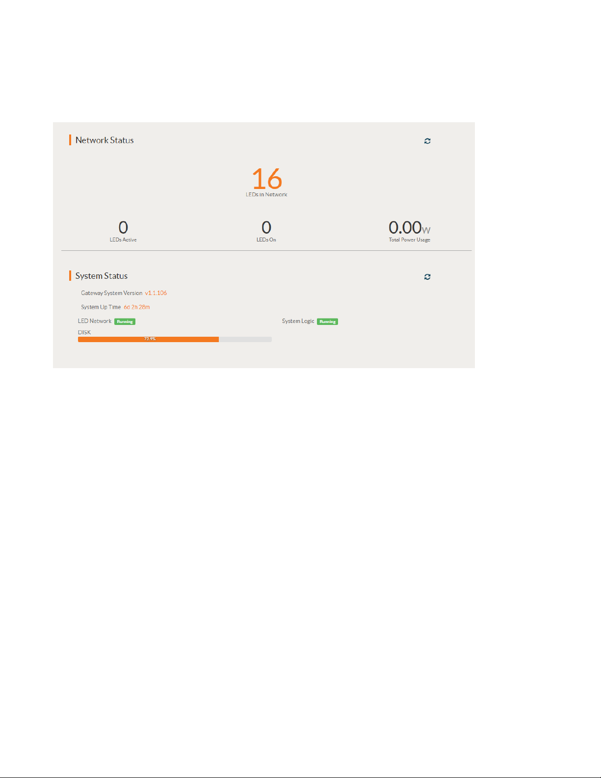
Network Status
To check the current network status, go to Dashboard page displayed on the Zum Outdoor LiteView
page.
The Network Status section displays the following:
l
LEDs in Network: Displays the number of nodes commissioned to the network.
l
LEDs Active: Displays the number of nodes that are currently powered up for communication.
l
LEDs On: Displays the number of LEDs that are currently turned on.
l
Total Power Usage: Displays the current total wattage of the LED system.
35 • ZUMNET-OD-GW-RF, ZUMMESH-OD-KOM, ZUMMESH-OD-7P Product Manual — Doc. 9376A
Page 36
Recent Activities
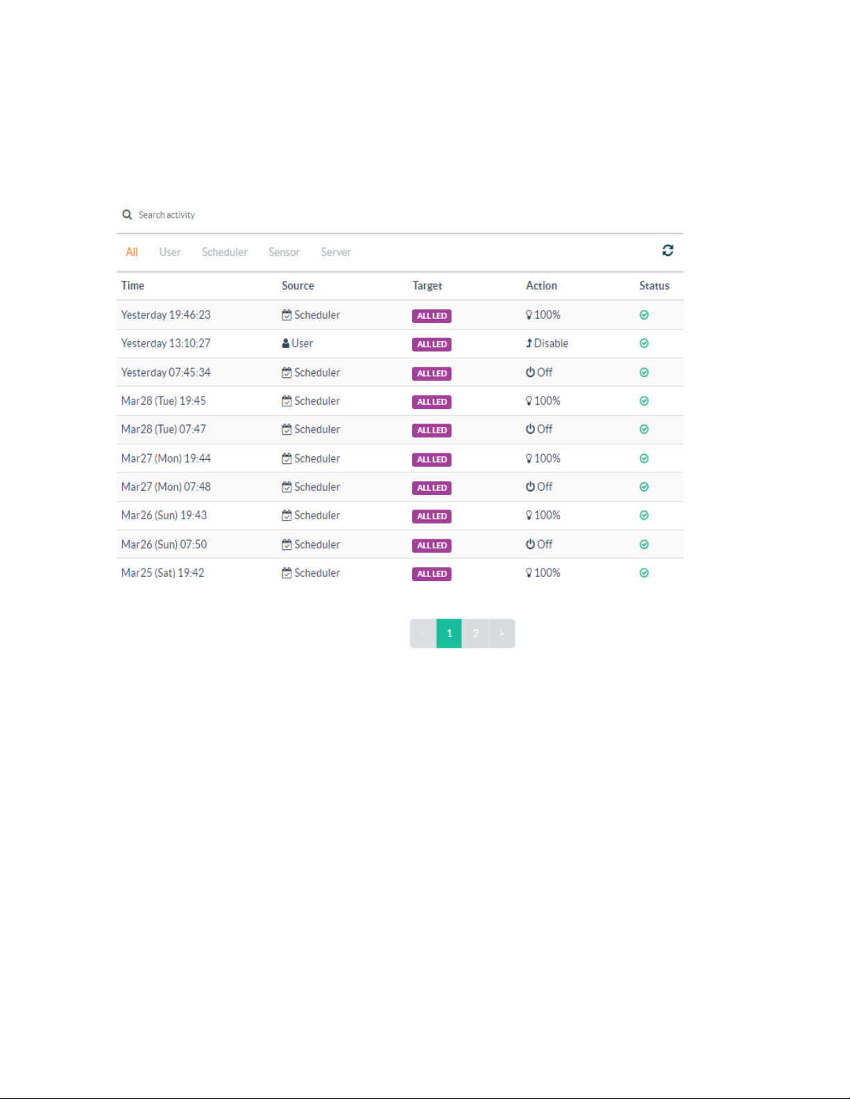
To check recent activities:
1. Go to the Dashboard page displayed on the Zum Outdoor LiteView page.
2. On the right side of the Dashboard page, the list of recent activities are displayed.
3. To filter the activities based on the initiator of the activity, select the All, User, Scheduler, Sensor,
or Server filter.
4. For each activity, you can identify the following:
a. Timestamp (Time)
b. The source of LED control action (Sender)
c. The target LEDs (Target)
d. The type of LED control (Action)
e. Its status (Status)
Product Manual — Doc. 9376A ZUMNET-OD-GW-RF, ZUMMESH-OD-KOM, ZUMMESH-OD-7P • 36
Page 37
Energy Monitor
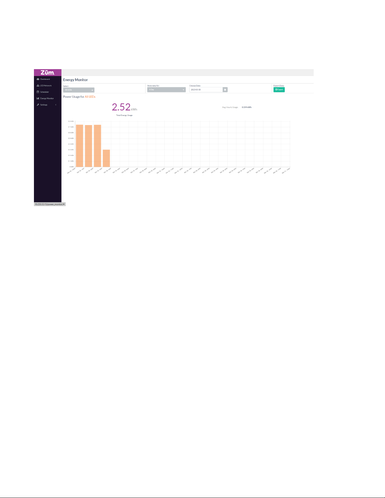
View and export energy usage for the system.
View Energy Usage
To view the energy usage:
1. Go to the Energy Monitor page displayed on the Zum Outdoor LiteView page.
2. For a single LED, under the Select drop-down, select a single LED to display the energy usage.
3. For a group of LEDs, under the Select drop-down, select the group of LEDs to display the energy
usage.
4. To check the energy usage for a day, under Show data for, choose a day from the Calendar
displayed.
5. To check the energy usage for a month, under Show data for, choose a month from the Calendar
displayed.
Export Energy Usage
To export the energy usage, filter the energy usage data as described in View Energy Usage on page 37
and then select Export.
37 • ZUMNET-OD-GW-RF, ZUMMESH-OD-KOM, ZUMMESH-OD-7P Product Manual — Doc. 9376A
Page 38
Upload a Map
To upload a map:
1. Go to LED Network and then select Map View.
2.
In the top-right corner, select Settings and then Upload Map.
NOTE: The image must be a BMP, JPG, or PNG format, cannot contain - or _, and must be less
than 10MB.
3. Select an image and then select OK.
To place node locations on the map:
1. Go to LED Network and then select Map View.
2.
Select Edit Locations.
3. Drag each node to its desired location. Select a node to get more details about the node.
4.
Select Confirm Locations.
Product Manual — Doc. 9376A ZUMNET-OD-GW-RF, ZUMMESH-OD-KOM, ZUMMESH-OD-7P • 38
Page 39

Node Management
Refer to the following sections for information on how to add, edit, and delete nodes.
This section provides the following information:
•Add a Node to the Network
•Remove a Node
•Edit a Node Description
39 • ZUMNET-OD-GW-RF, ZUMMESH-OD-KOM, ZUMMESH-OD-7P Product Manual — Doc. 9376A
Page 40
Add a Node to the Network
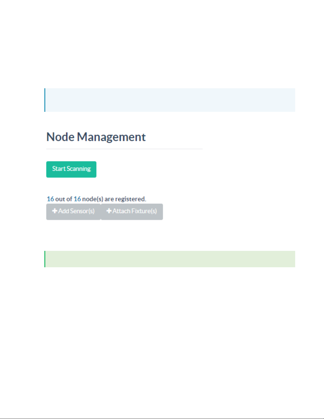
To add a node to the network:
1. Confirm all of the nodes are powered up.
2. Go to Settings > Node Management.
3. To search for nodes, select Start Scanning. The nodes that are discovered are displayed in the
Nodes list. Nodes that are not registered are displayed with a yellow background.
NOTE: The number of nodes in the system is displayed below the Start Scanning and Stop
Scanning button. The number of unregistered nodes is also shown.
When all nodes are displayed, select Stop Scanning.
4. For each unregistered node, enter the ID, Description, and Location, and then select Register.
Upon successful registration, the node's background will change to white.
TIP: The ID, Description, and Location is used for reference while commissioning the system.
Product Manual — Doc. 9376A ZUMNET-OD-GW-RF, ZUMMESH-OD-KOM, ZUMMESH-OD-7P • 40
Page 41
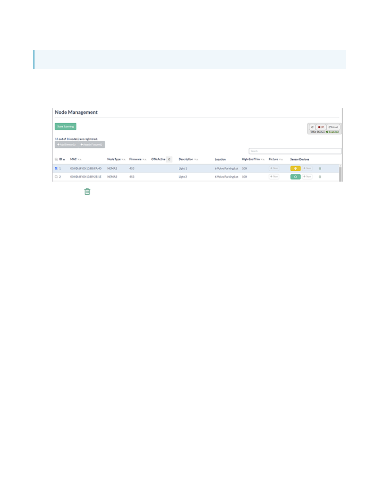
Remove a Node
NOTE: The related data (schedules, activity history, and energy usage data) will also be removed.
To remove a node:
1. Go to Settings >Node Management.
2. Select the row containing the target node set for deletion.
3.
Select the Delete and then Remove Node to confirm.
41 • ZUMNET-OD-GW-RF, ZUMMESH-OD-KOM, ZUMMESH-OD-7P Product Manual — Doc. 9376A
Page 42
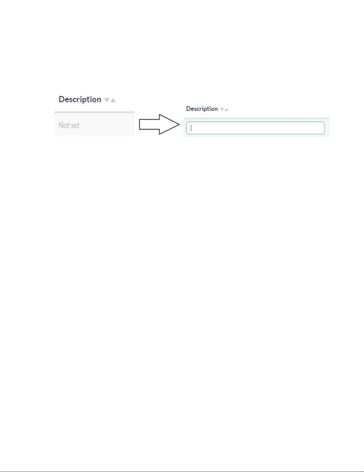
Edit a Node Description
To edit a node description:
1. Go to Settings > Node Management.
2. Double-click the Not set field. The border of the text box color changes to green and values can be
entered.
3. To save, click outside the text box.
A green notification is displayed at the top of the screen to indicate that the change was
successful.
Product Manual — Doc. 9376A ZUMNET-OD-GW-RF, ZUMMESH-OD-KOM, ZUMMESH-OD-7P • 42
Page 43

Group Management
Refer to the following sections for information on how to create or delete a group and how to add a
node to a group.
This section provides the following information:
•Create and Rename Groups
•Add a Node to a Group
•Delete a Node from a Group
•Delete a Group
43 • ZUMNET-OD-GW-RF, ZUMMESH-OD-KOM, ZUMMESH-OD-7P Product Manual — Doc. 9376A
Page 44
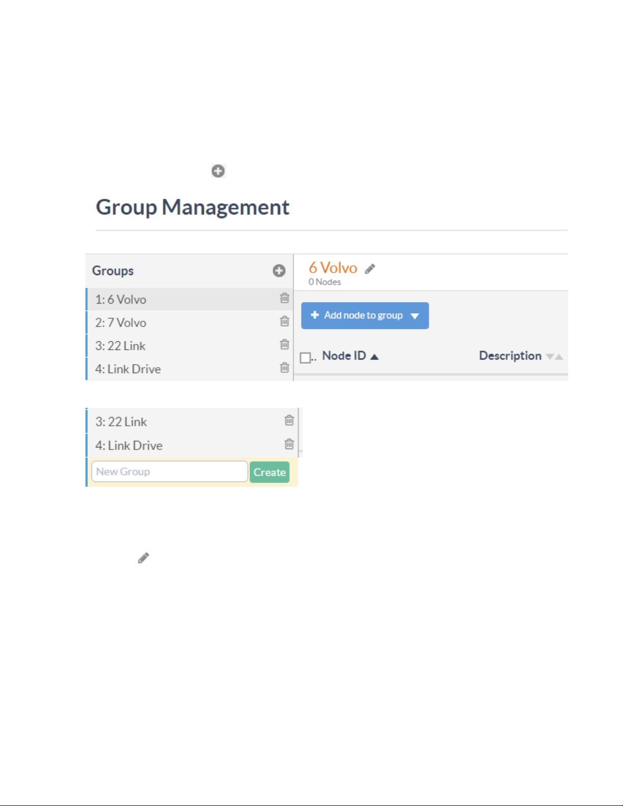
Create and Rename Groups
Create and rename groups in the system.
Create a New Group
To create a new group:
1. Go to Settings >Group Management.
2.
On the Groups list, select AddGroup.
3. Enter the group name in the New Group field and then select Create.
Edit a Group Name
To change the name of a group:
1.
Select the Edit Group next to the existing group name.
2. Enter the group name in the group name field.
Product Manual — Doc. 9376A ZUMNET-OD-GW-RF, ZUMMESH-OD-KOM, ZUMMESH-OD-7P • 44
Page 45
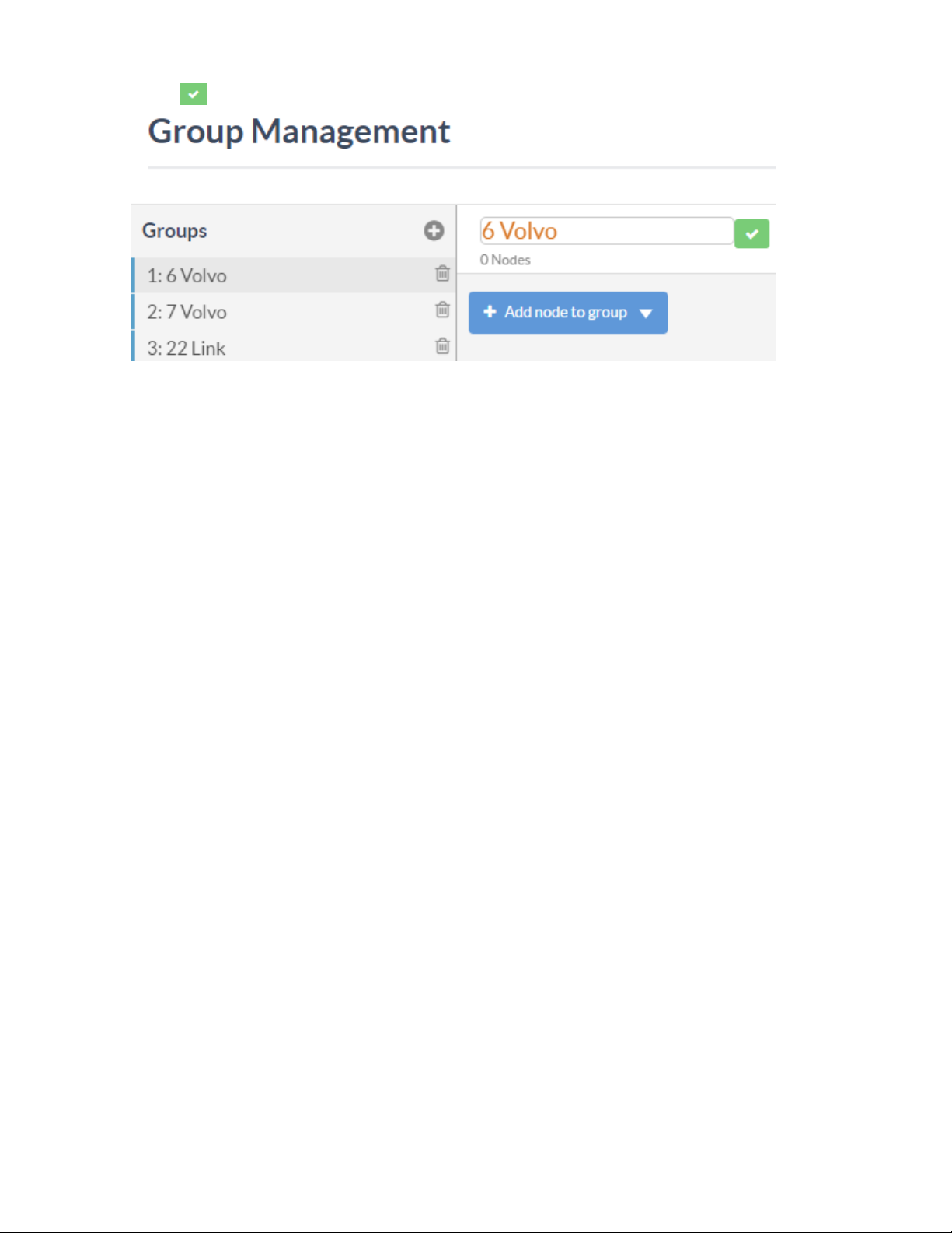
3.
Select Save.
45 • ZUMNET-OD-GW-RF, ZUMMESH-OD-KOM, ZUMMESH-OD-7P Product Manual — Doc. 9376A
Page 46
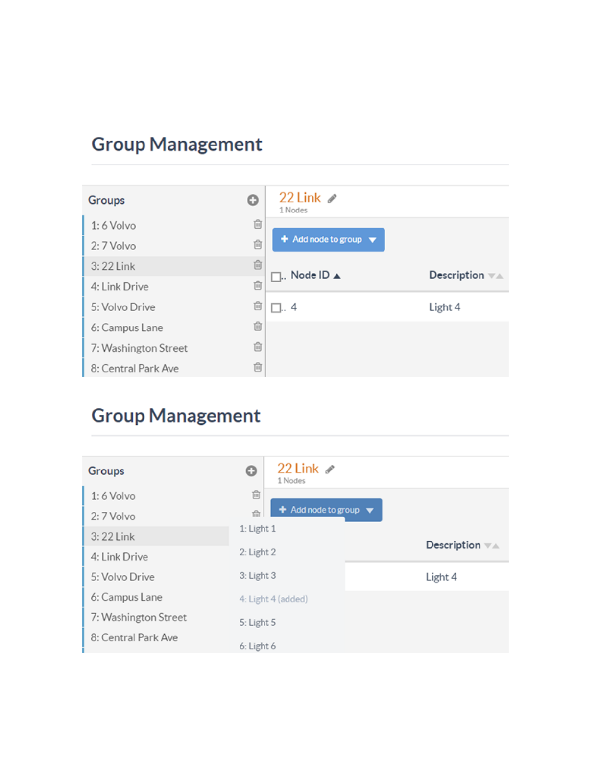
Add a Node to a Group
To add a node to a group:
1. Go to Settings >Group Management.
2. On the Group Management section, select a group from the Groups list.
3. Select Add node to group, and then select a node from the list of nodes.
Product Manual — Doc. 9376A ZUMNET-OD-GW-RF, ZUMMESH-OD-KOM, ZUMMESH-OD-7P • 46
Page 47
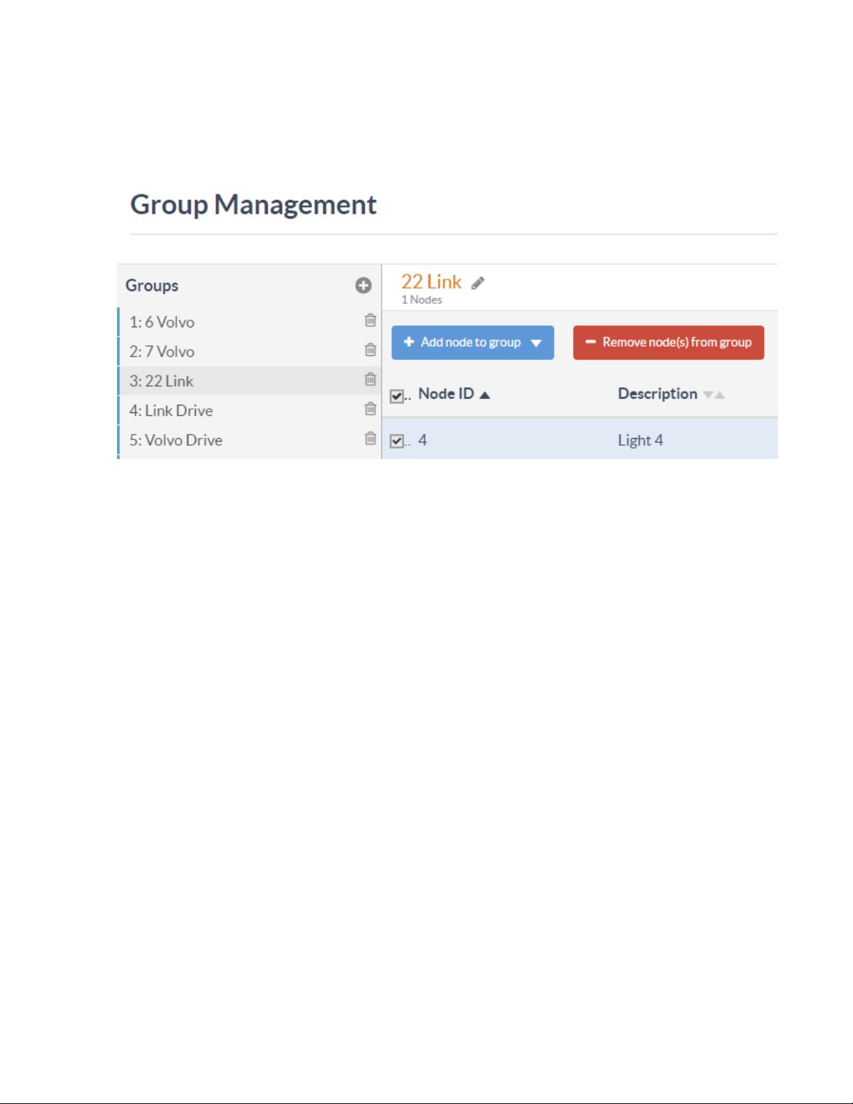
Delete a Node from a Group
To delete a node from a group:
1. Go to Settings >Group Management.
2. On the Group Management section, select a group from the Groups list.
3. In the Nodes list, select a node to remove and then select Remove node(s) from group..
47 • ZUMNET-OD-GW-RF, ZUMMESH-OD-KOM, ZUMMESH-OD-7P Product Manual — Doc. 9376A
Page 48
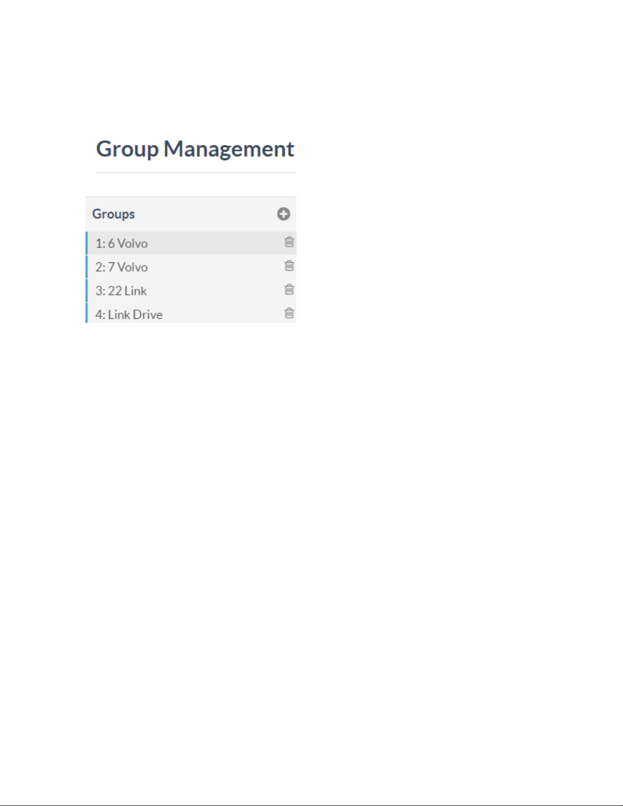
Delete a Group
To delete a group:
1. Go to Settings > Group Management.
2. On the Group Management section, select the group to be deleted, and then select Delete.
Product Manual — Doc. 9376A ZUMNET-OD-GW-RF, ZUMMESH-OD-KOM, ZUMMESH-OD-7P • 48
Page 49

LED Control
Refer to the following sections for information on how to control a single LED, group of LEDs or all the
LEDs. In addition, the voltage, power consumption, and current can be checked in real-time.
This section provides the following information:
•Control a Single LED
•Control a Group of LEDs
•Control all LEDs
•Check Real-time Power Reading, Voltage, and Current
49 • ZUMNET-OD-GW-RF, ZUMMESH-OD-KOM, ZUMMESH-OD-7P Product Manual — Doc. 9376A
Page 50
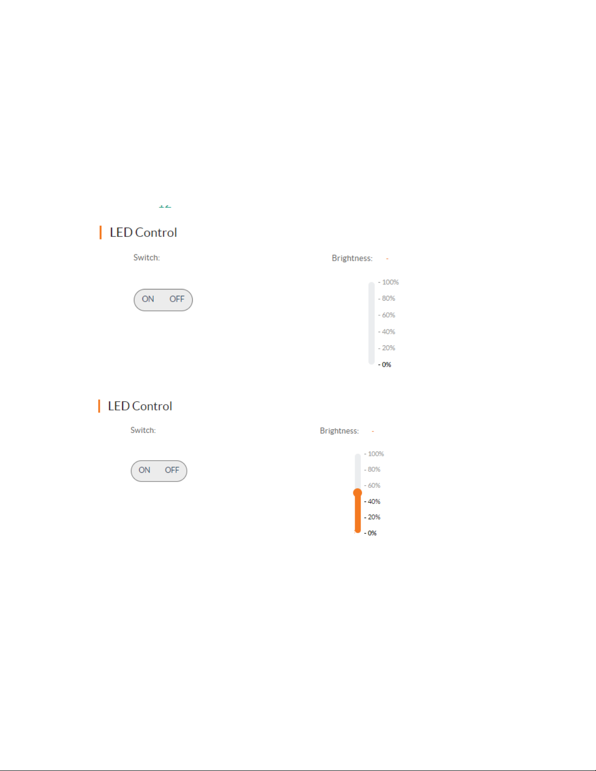
Control a Single LED
To control a single LED:
1. Go to LED Network section and select Grid View tab.
2. Select the target LED.
3. Select On or Off to turn the LED on or off. A blue circle indicates that the LED is on, and a red
circle indicates that the LED is off.
4. Drag the Brightness slider under LED Control up or down to adjust the brightness. The blue circle
around the LED icon will change according to the current brightness level of the LED. For
example, a full circle indicates 100% brightness, and a quarter of a circle indicates 25% brightness.
Product Manual — Doc. 9376A ZUMNET-OD-GW-RF, ZUMMESH-OD-KOM, ZUMMESH-OD-7P • 50
Page 51
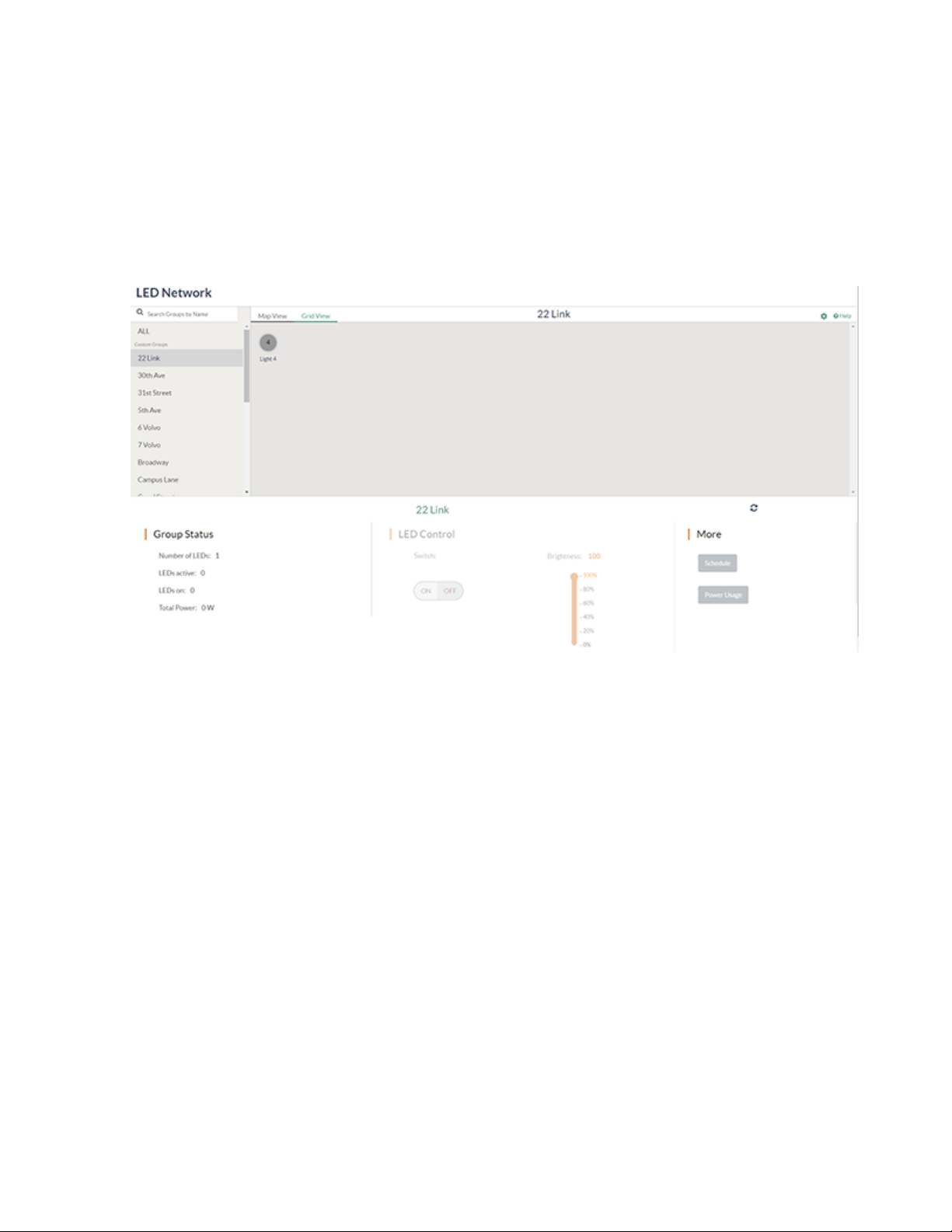
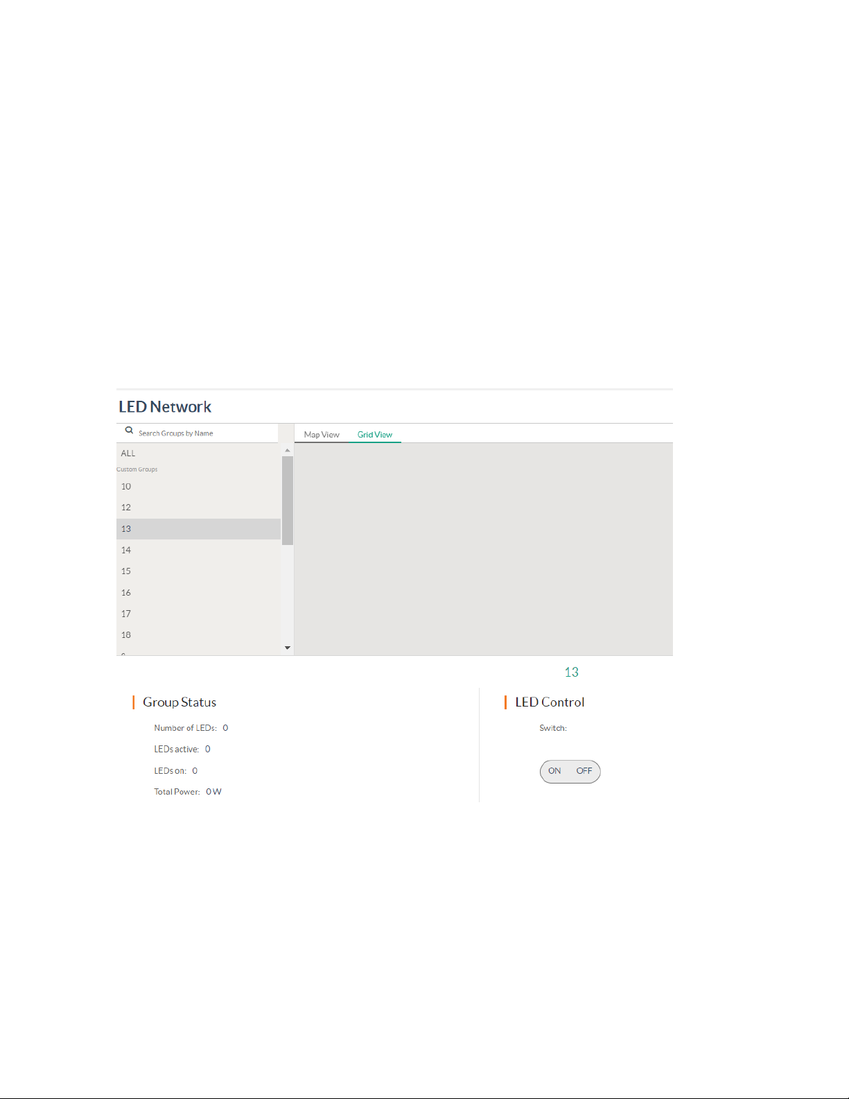
Control a Group of LEDs
To control a group of LEDs:
1. Go to the LED Network section.
2. On the LED Network section, select the target group of LEDs. The control buttons are displayed
at the bottom-center of the page.
3. Select On or Off to turn the LED on or off.
4. In the LED Network section, drag the slider to the desired brightness.
51 • ZUMNET-OD-GW-RF, ZUMMESH-OD-KOM, ZUMMESH-OD-7P Product Manual — Doc. 9376A
Page 52
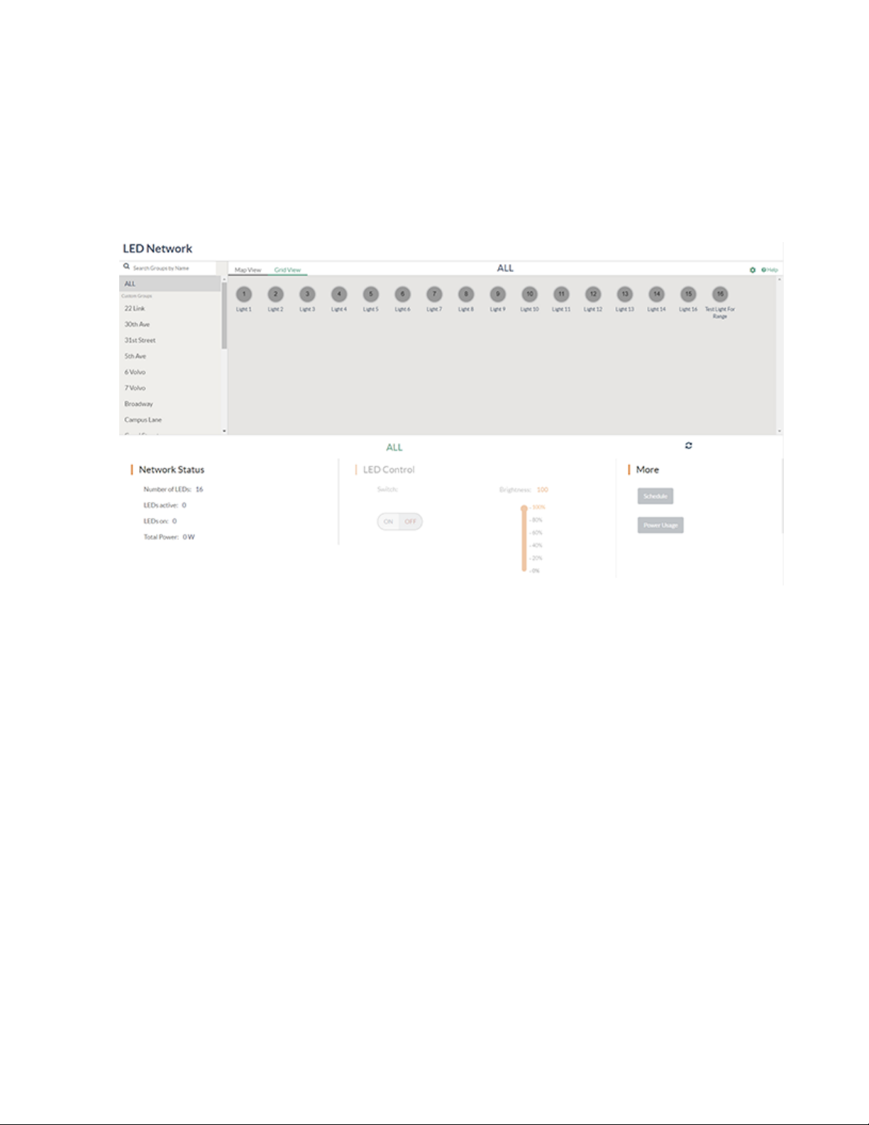
Control all LEDs
To control all LEDs:
1. Go to the LED Network section.
2. On the LED Network section, select All.
3. Select On or Off to turn the LED on or off.
4. Drag the Brightness slider under LED Control up or down to adjust the brightness.
Product Manual — Doc. 9376A ZUMNET-OD-GW-RF, ZUMMESH-OD-KOM, ZUMMESH-OD-7P • 52
Page 53
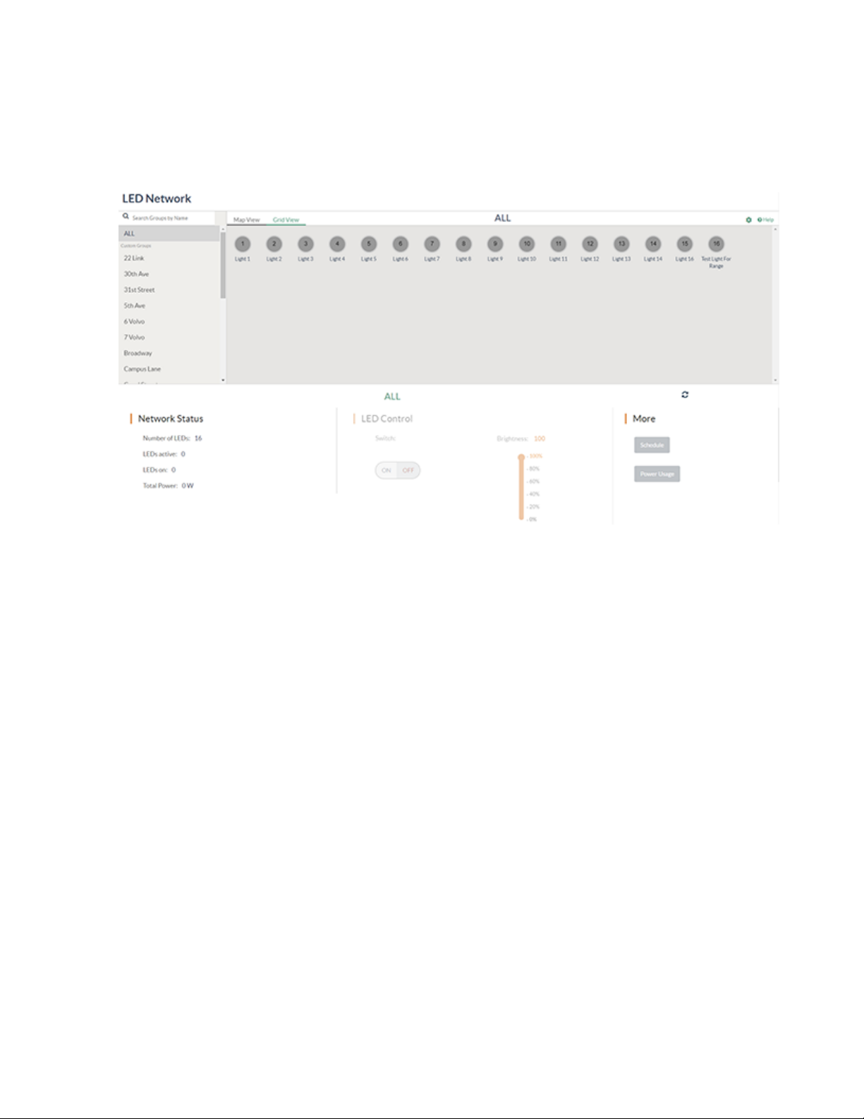
Check Real-time Power Reading, Voltage, and Current
To check real-time power reading, voltage, and current:
1. Go to the LED Network page.
2. Select the target LED. The LED Node Details appears with a summary for the selected LED.
53 • ZUMNET-OD-GW-RF, ZUMMESH-OD-KOM, ZUMMESH-OD-7P Product Manual — Doc. 9376A
Page 54

Sensor Management
Refer to the following sections for information on how to add, delete, enable or disable a sensor or
group of sensors. In addition, target devices can be set for the sensor.
This section provides the following information:
•Add a Sensor to a Node
•Filter the List of Sensors
•Enable or Disable a Sensor
•Enable or Disable all Sensors
•Set the Target to a Single LED
•Set the Target to a Group of LEDs
•Set the Target to All LEDs on the Gateway
•Occupancy Sensor Specific Actions
•Daylight Sensor Rules
•Delete a Sensor
Product Manual — Doc. 9376A ZUMNET-OD-GW-RF, ZUMMESH-OD-KOM, ZUMMESH-OD-7P • 54
Page 55
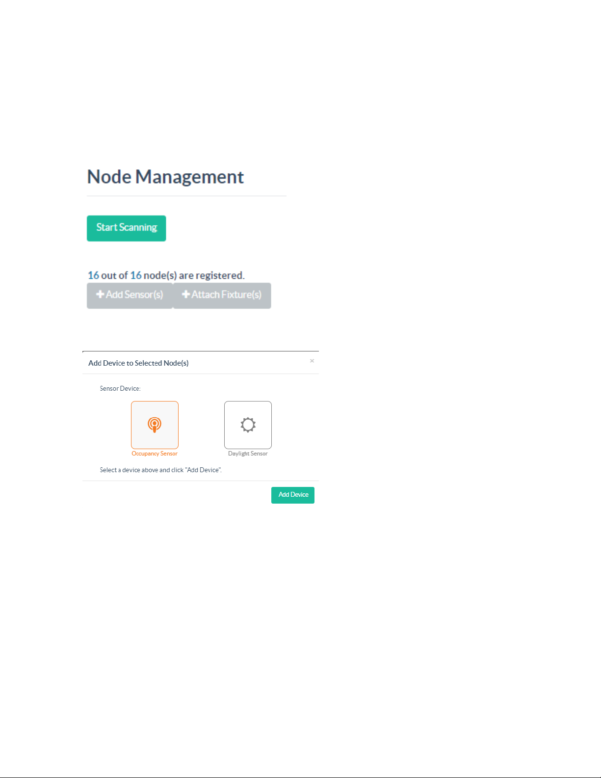
Add a Sensor to a Node
An Occupancy Sensor or a Daylight sensor can be added to a node.
To add a sensor to a node:
1. Go to Settings > Node Management. The list of available nodes are displayed.
2. Select the node and select +Add Sensor.
3. In the Add Device to Selected Node(s) menu, select Occupancy Sensor or Daylight Sensor.
4. Select Add Device.
55 • ZUMNET-OD-GW-RF, ZUMMESH-OD-KOM, ZUMMESH-OD-7P Product Manual — Doc. 9376A
Page 56
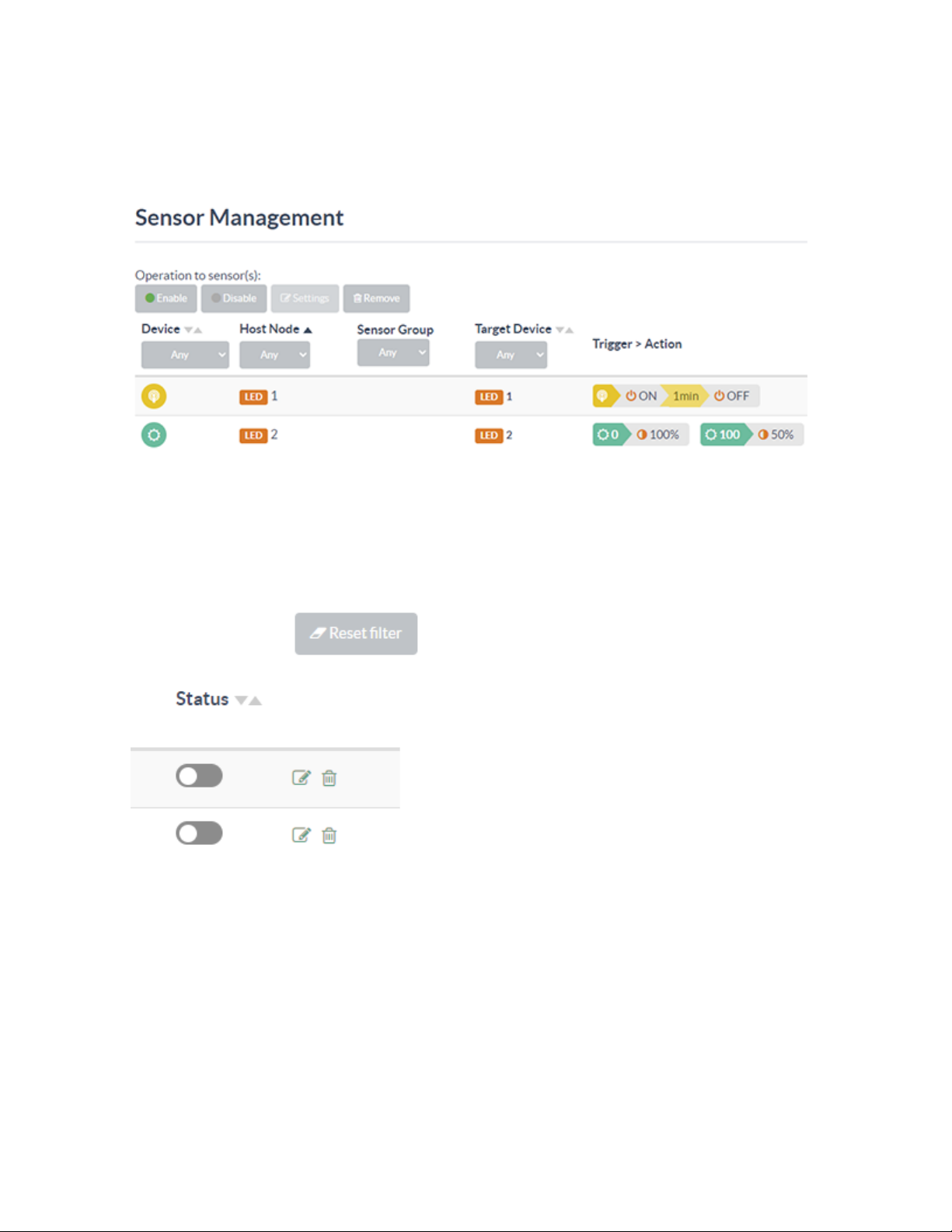
Filter the List of Sensors
To filter the list of sensors:
1. By default, all sensors appear in the sensor list. The list can be filtered to display by device type,
host node, group, target device, or in combination.
l
The Device drop-down menu contains Any, Occupancy, and Daylight options.
l
The Host Node drop-down menu contains Any and the list of host node options.
l
The Sensor Group drop-down menu contains Any and the list of sensor group.
l
The Target Device drop-down menu contains Any and the list of target devices.
2. Select Reset filter to clear the filters and display the default list of sensors.
Product Manual — Doc. 9376A ZUMNET-OD-GW-RF, ZUMMESH-OD-KOM, ZUMMESH-OD-7P • 56
Page 57
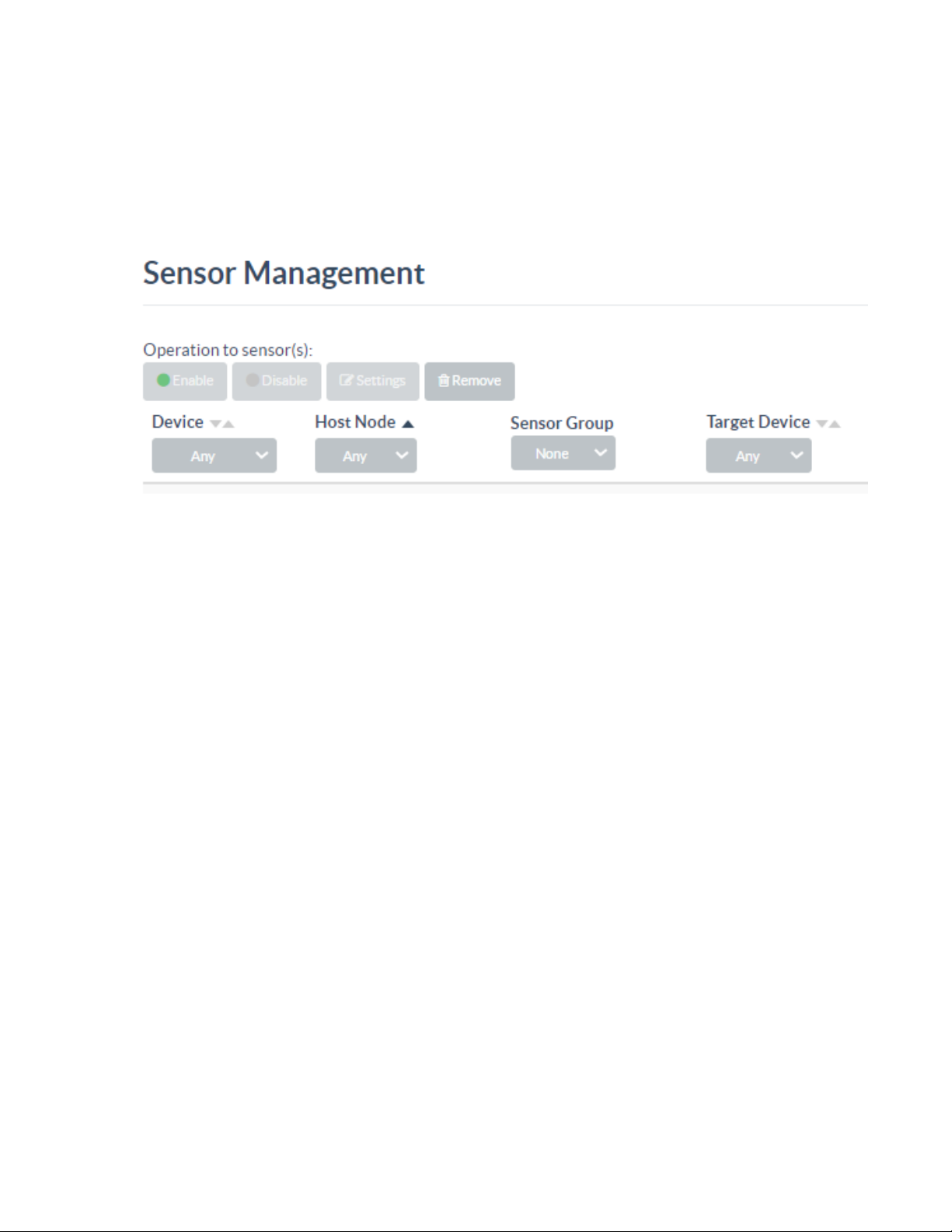
Enable or Disable a Sensor
To enable or disable a sensor:
1. Go to Settings > Sensor Management. By default, a sensor is disabled when first added and must
be manually enabled.
2. Select Enable to enable the selected sensor. All added sensors are identified by the node they are
connected to and listed accordingly.
57 • ZUMNET-OD-GW-RF, ZUMMESH-OD-KOM, ZUMMESH-OD-7P Product Manual — Doc. 9376A
Page 58
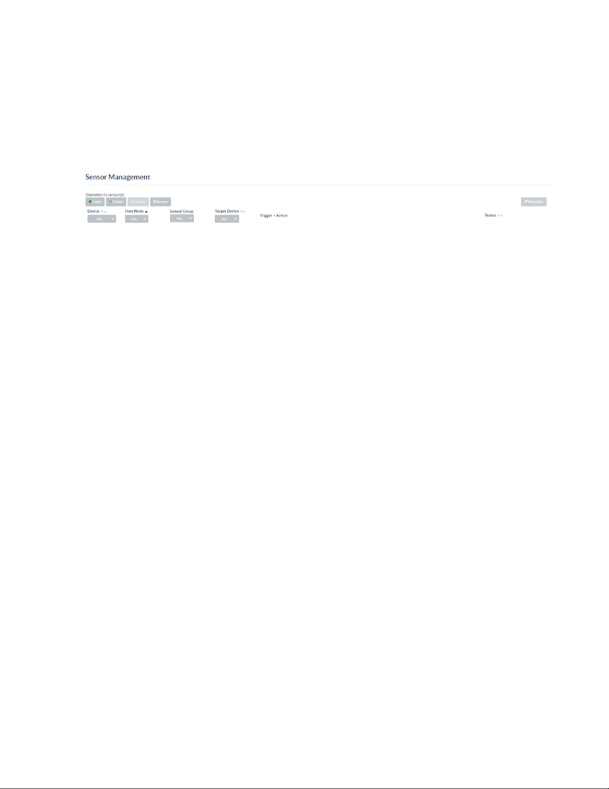
Enable or Disable all Sensors
To enable or disable all sensors:
1. Go to Settings > Sensor Management. To enable or disable all sensors, the filters must be in the
default mode.
2. Select Reset filter located at the top left corner of the Sensor Management page for the filters to
be listed in the default mode.
3. Select the Enable or the Disable button.
4. Click Confirm in the Enable Sensor Conformation or Disable Sensor Confirmation window to
enable or disable all sensors.
Product Manual — Doc. 9376A ZUMNET-OD-GW-RF, ZUMMESH-OD-KOM, ZUMMESH-OD-7P • 58
Page 59
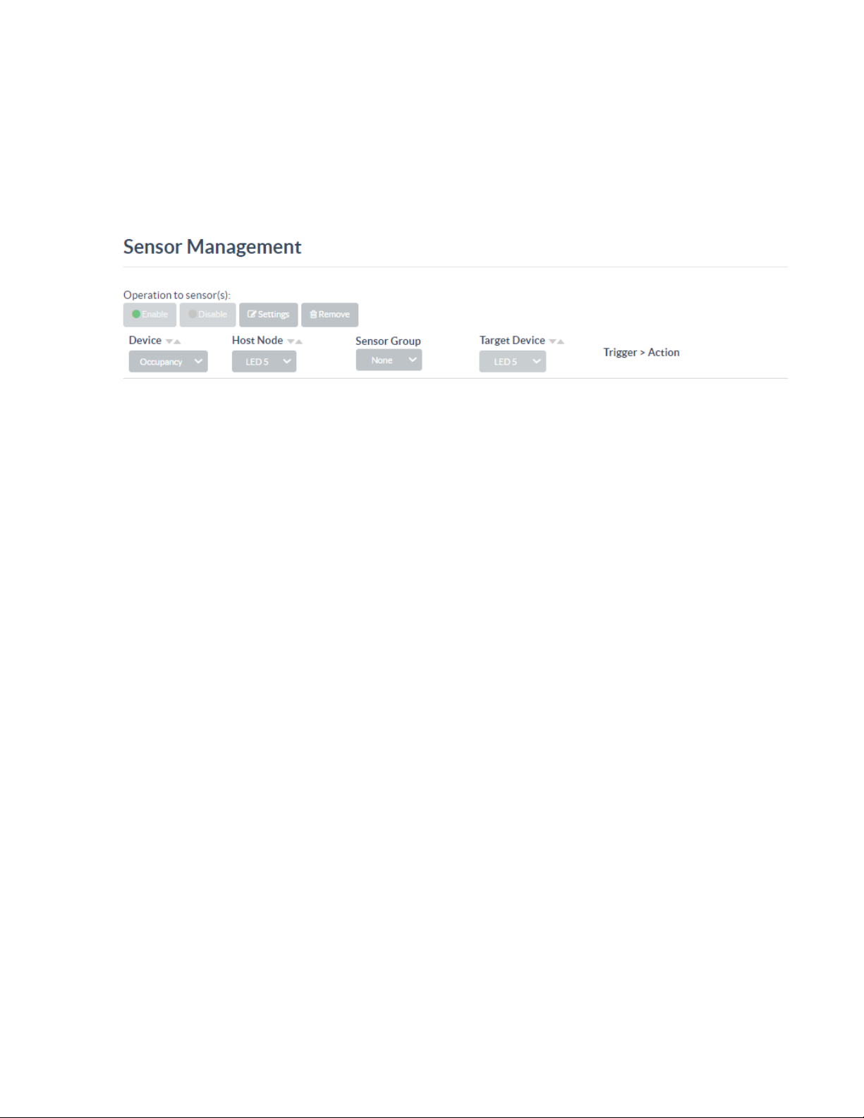
Set the Target to a Single LED
To set the target to a single LED:
1. Go to Settings > Sensor Management.
2. Select the target device from the Target Device drop-down menu.
3. Select a single LED from the Host Node drop-down menu.
59 • ZUMNET-OD-GW-RF, ZUMMESH-OD-KOM, ZUMMESH-OD-7P Product Manual — Doc. 9376A
Page 60
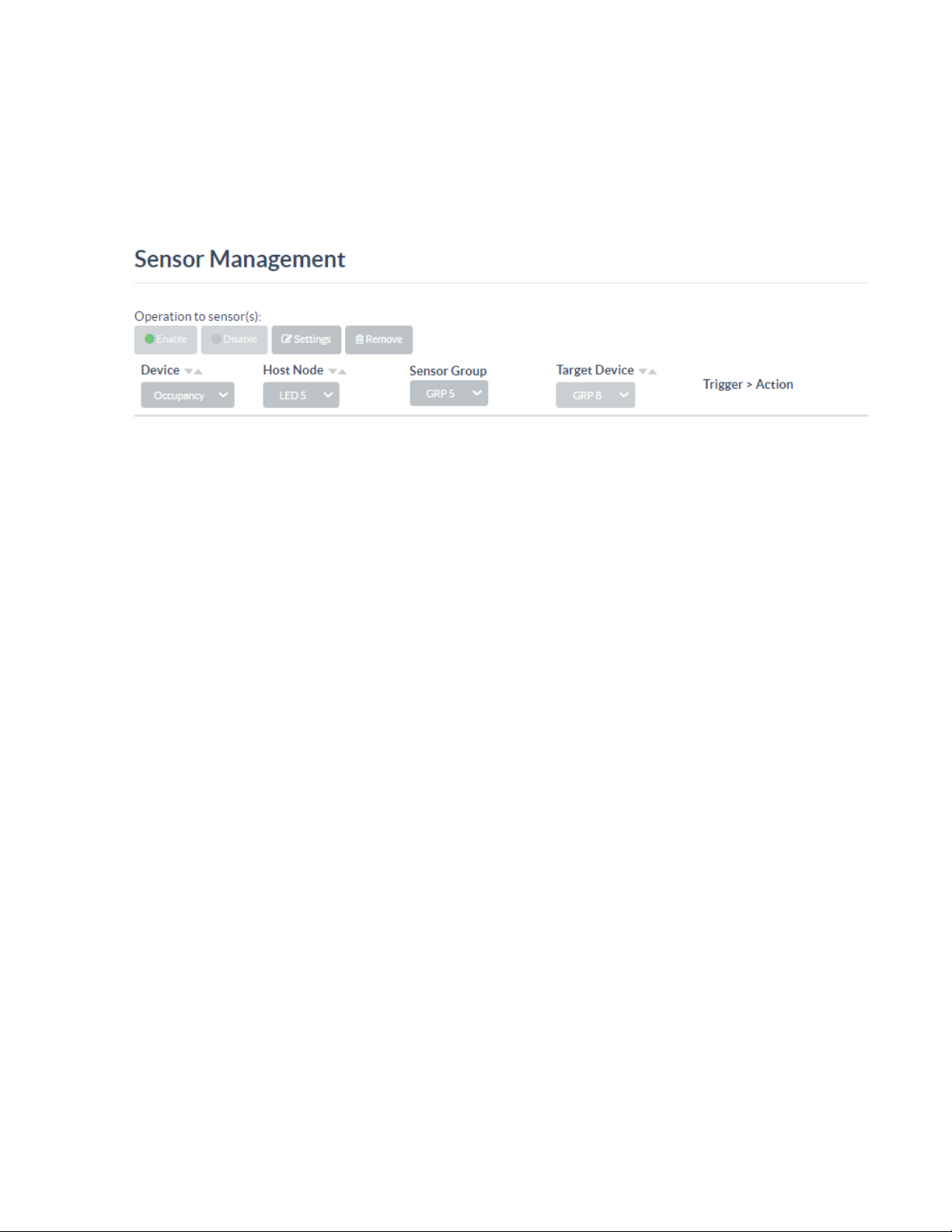
Set the Target to a Group of LEDs
To set the target to a group of LEDs:
1. Go to Settings > Sensor Management.
2. Select the target device from the Target Device drop-down menu to set the target.
3. Select the LED group from the Host Node drop-down menu.
Product Manual — Doc. 9376A ZUMNET-OD-GW-RF, ZUMMESH-OD-KOM, ZUMMESH-OD-7P • 60
Page 61
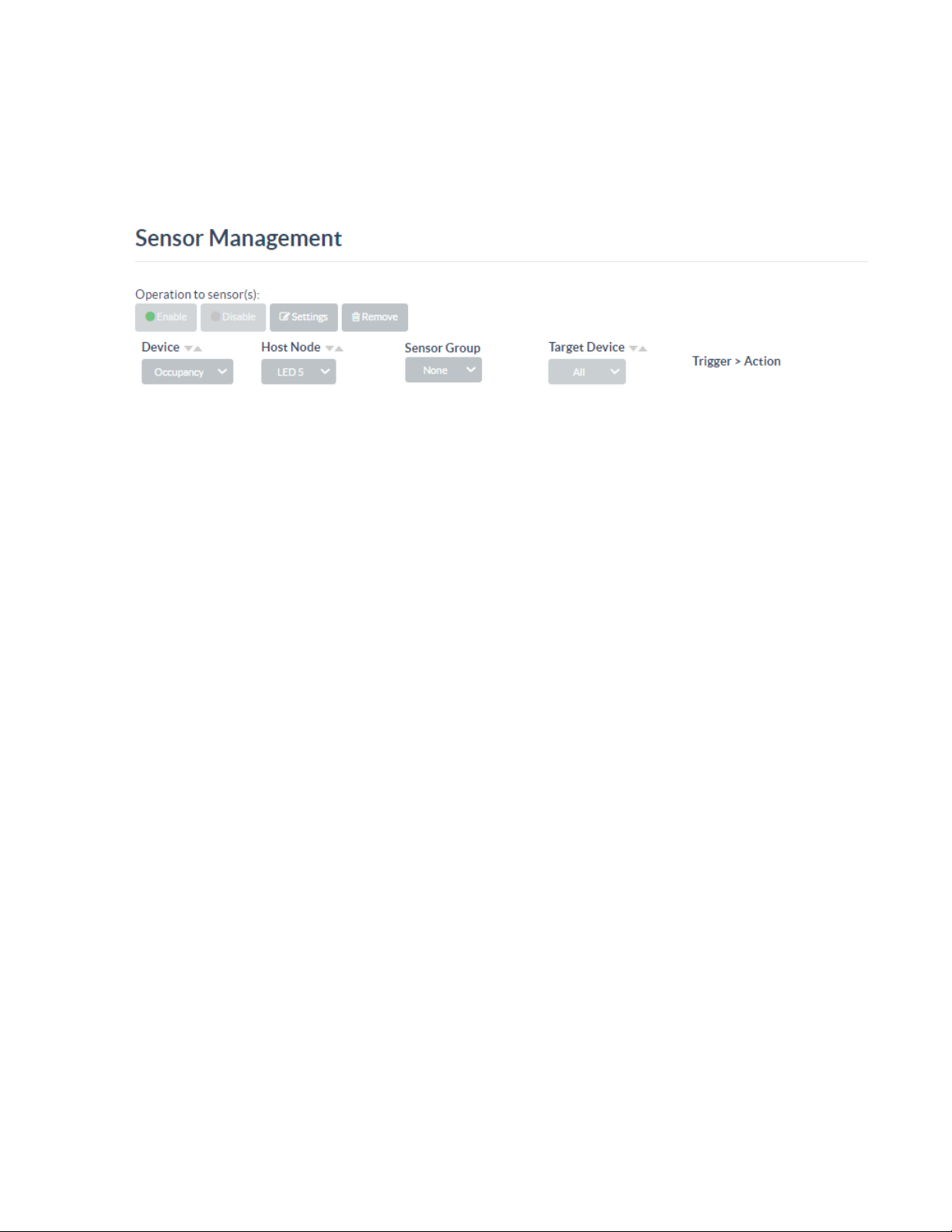
Set the Target to All LEDs on the Gateway
To set the target to all the LEDs on the Gateway:
1. Go to Settings > Sensor Management.
2. Select All from the Target Device drop-down list to set the target.
61 • ZUMNET-OD-GW-RF, ZUMMESH-OD-KOM, ZUMMESH-OD-7P Product Manual — Doc. 9376A
Page 62
Occupancy Sensor Specific Actions
The occupancy sensor specific actions provide information after the selected sensor is triggered. The
different actions are:
1. To change the initial brightness level after trigger, change the value in the Brightness text box to
the desired brightness level .
2. To change the delay between the trigger and section action (by default, it is set to off) from the
default of one minute, change the value in the After no motion text box. This delay must be whole
numbers and can be no less than one.
To set up the follow-up rule for the motion sensor to turn off after one minute:
1. Select Add Follow-up Rule.
2. Set the intermediate brightness and delay for the action in the Brightness and the After no
motion for text boxes, respectively.
3. Select Switch ON/OFF to turn the LED on or off.
Product Manual — Doc. 9376A ZUMNET-OD-GW-RF, ZUMMESH-OD-KOM, ZUMMESH-OD-7P • 62
Page 63

Daylight Sensor Rules
Daylight sensor rules can be set up to control the light based on ambient light levels.
Change Action
To change the brightness:
1. To change the brightness level based on ambient light levels, select Set Brightness under the
Action column.
2. To turn the light On or Off based on ambient light levels, select Switch under the Action column.
Change Range for Ambient Light Levels
Only the lower range for ambient light levels can be changed.
1. To change the range of the first level, double-click the lower range of the level below the first level.
2. Enter a value higher than the new lower range of the level to change. For example, if you want to
change the range of the first level from 0-99 to 0-300.
3. The lower range of the higher level changes automatically.
63 • ZUMNET-OD-GW-RF, ZUMMESH-OD-KOM, ZUMMESH-OD-7P Product Manual — Doc. 9376A
Page 64
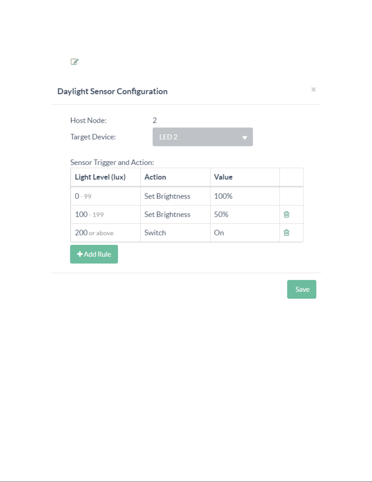
Add a Rule
To add a rule:
1.
Select Edit for a daylight sensor.
2. In the Daylight Sensor Configuration window, select Add Rule.
3. Configure the rule:
l
Light Level (lux): The light level assigned to trigger the rule. To assign a light level, select the
Light Level and then enter a value.
l
Action: The function that is performed when the rule is triggered. To assign an action, select
the Action and then select Set Brightness or Switch.
l
Value: The brightness level of the light. To assign a value when Set Brightness is selected,
enter a light value between 0 and 100% brightness. To assign a value when Switch is
selected, select On or Off.
4. Select Save.
Product Manual — Doc. 9376A ZUMNET-OD-GW-RF, ZUMMESH-OD-KOM, ZUMMESH-OD-7P • 64
Page 65
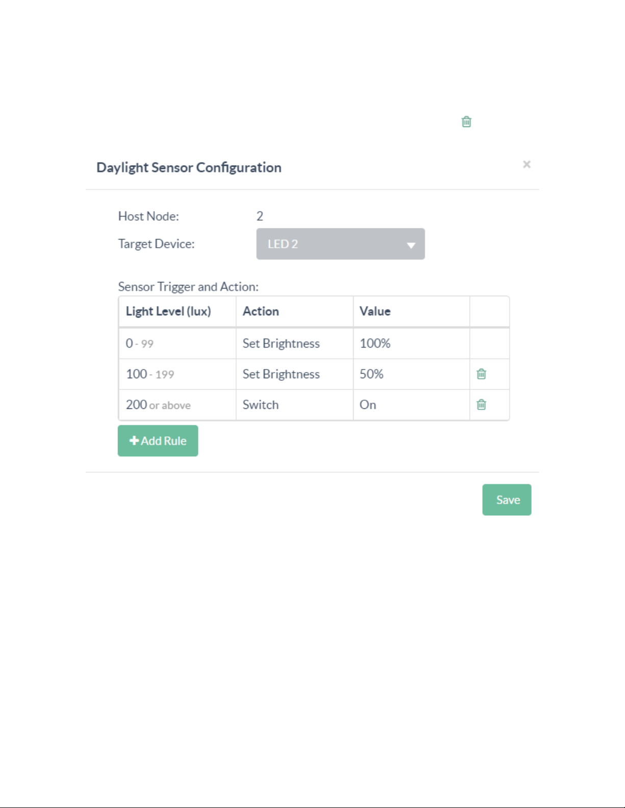
Delete a Rule
To delete a rule:
1. Select Edit for a daylight sensor.
2.
In the Daylight Sensor Configuration window, identify a rule and then select Delete. The other
levels will adjust their bounds for the removed level.
3. Select Save or X to close.
65 • ZUMNET-OD-GW-RF, ZUMMESH-OD-KOM, ZUMMESH-OD-7P Product Manual — Doc. 9376A
Page 66
Delete a Sensor
Delete a sensor using the Node Management page or Sensor Management page.
Delete Sensor using the Node Management Page
To delete a sensor from the Node Management page:
1. Go to Settings > Node Management.
a. From the list, locate the node you want to delete a sensor from.
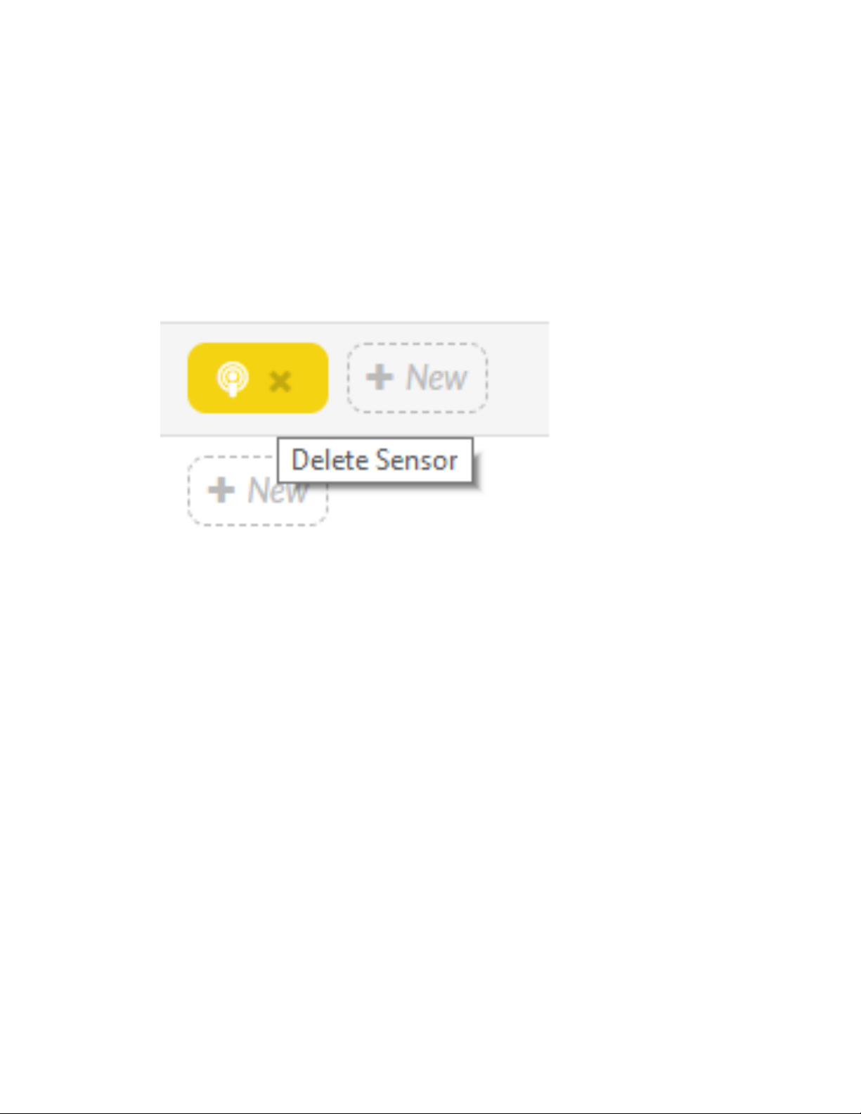
b. Hover over the corresponding sensor icon on the right side of the page, and note that an x
appears in the button.
c. Select x, and a select Confirm for deletion.
Delete Sensor using the Sensor Management Page
To delete a sensor using the Sensor Management page:
1. Go to Settings > Sensor Management.
2. Locate the row that lists the sensor and select the sensor for deletion.
3. Select Delete on the right-hand side of the page.
4. Select Remove Sensor to confirm deletion. The sensor and the corresponding rules are deleted. To
delete multiple sensors, filter the list of sensors to list all sensor rules to deleted.
Product Manual — Doc. 9376A ZUMNET-OD-GW-RF, ZUMMESH-OD-KOM, ZUMMESH-OD-7P • 66
Page 67
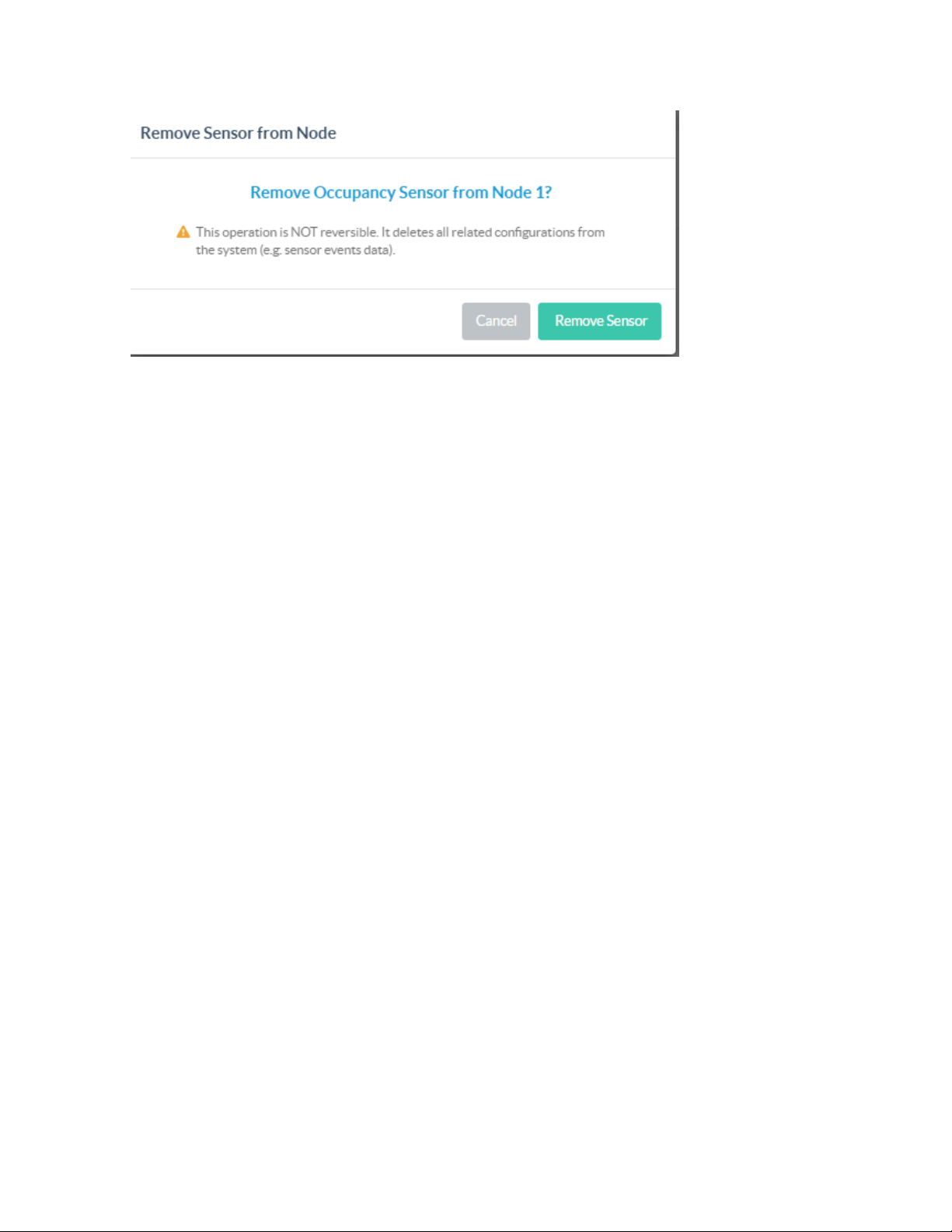
5. Select Remove.
67 • ZUMNET-OD-GW-RF, ZUMMESH-OD-KOM, ZUMMESH-OD-7P Product Manual — Doc. 9376A
Page 68

Scheduling
Refer to the following sections for information on how to schedule different actions such as power on or
off, and offset time for LEDs and sensors.
This section provides the following information:
•Add a Schedule
•Schedule for a Single LED
•Schedule for a Group of LEDs
•Add Schedule for all the LEDs
•Schedule the On or Off Time Set Control for an LED
•Schedule the Brightness Control
•Set a Schedule for an LED to Turn On at a Specific Time and Date
•Set a Schedule for an LED to Turn On at Sunrise or Sunset
•Set a Repeating Schedule for an LEDor Sensor
•Set a Schedule for the Sensors
•Delete a Schedule
Product Manual — Doc. 9376A ZUMNET-OD-GW-RF, ZUMMESH-OD-KOM, ZUMMESH-OD-7P • 68
Page 69
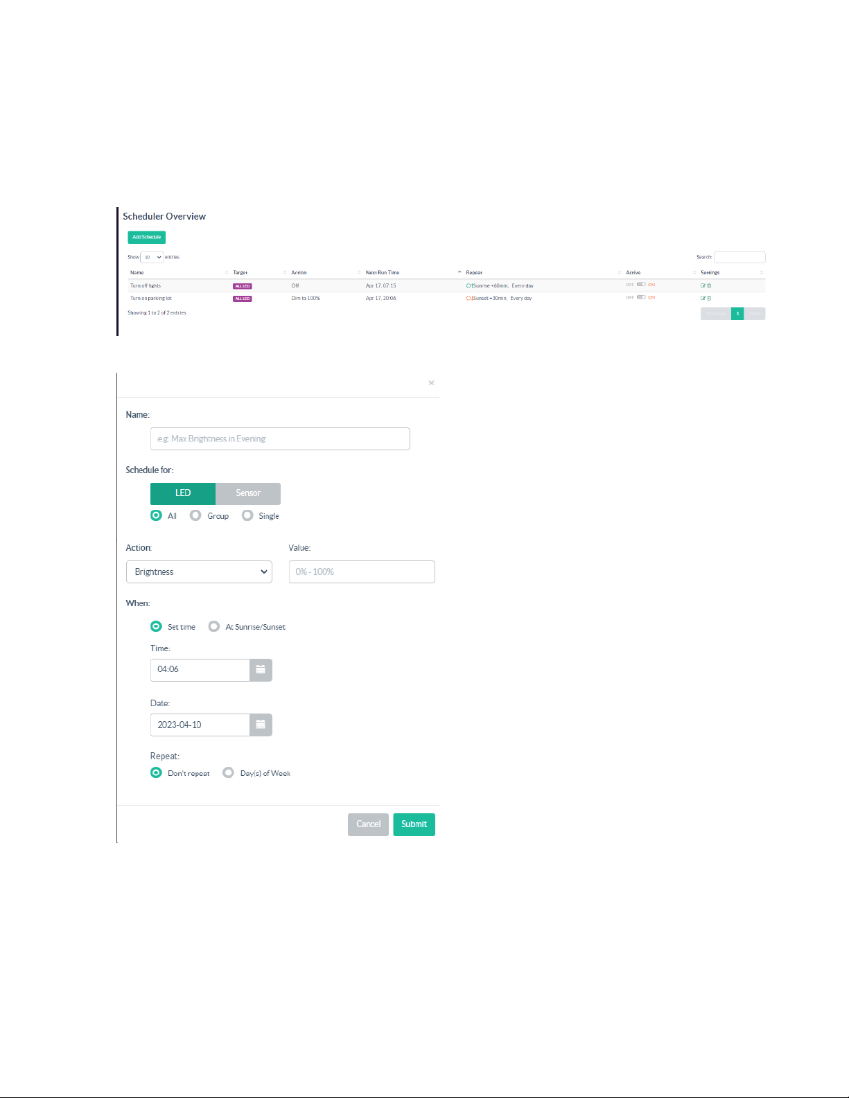
Add a Schedule
To add a schedule:
1. Select Scheduler from the main menu displayed on the right side of the Zum Outdoor LiteView
web page.
2. Select Add Schedule.
3. Enter the schedule name, scheduling for, action, and time in the displayed screen.
4. Select Submit.
69 • ZUMNET-OD-GW-RF, ZUMMESH-OD-KOM, ZUMMESH-OD-7P Product Manual — Doc. 9376A
Page 70
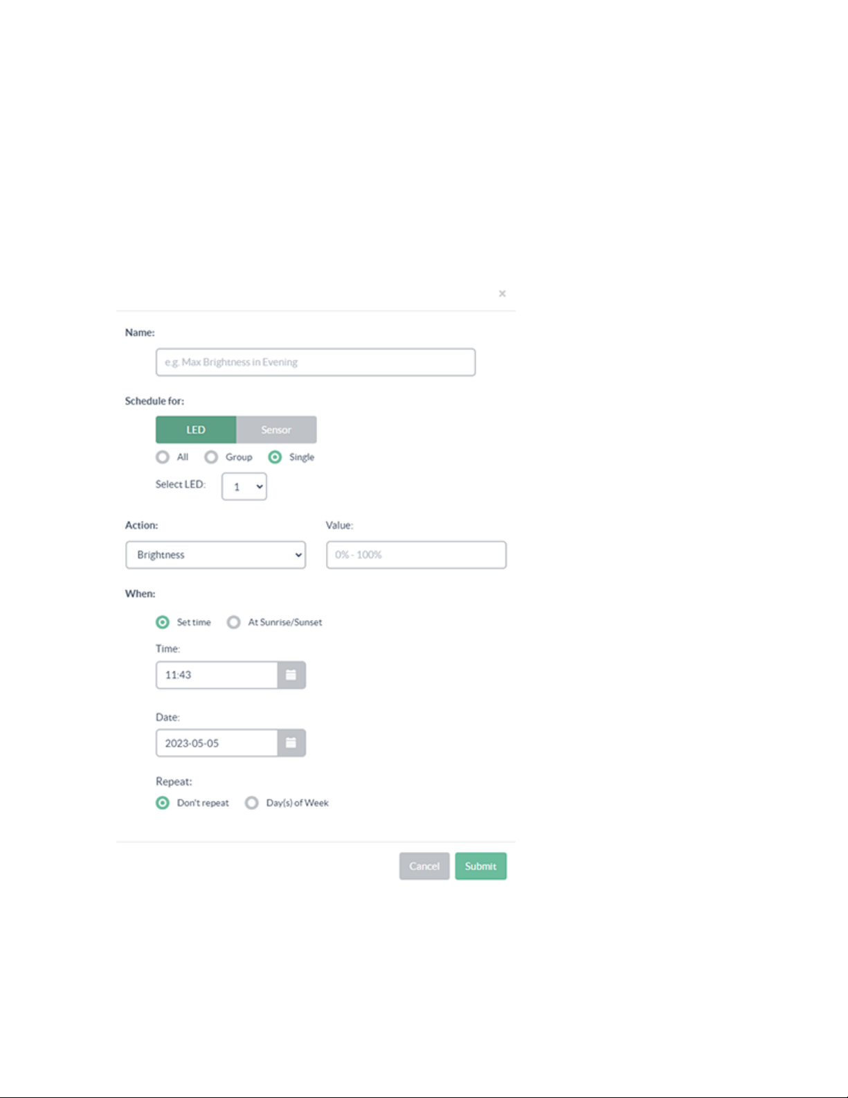
Schedule for a Single LED
To add a schedule for a single LED:
1. Select Scheduler from the main menu displayed on the right side of the Zum Outdoor LiteView
web page.
2. In the Select LED drop-down menu, select the target LED.
3. Select LED and Single under Schedule for.
4. Enter the schedule name, scheduling target, action, and time in the displayed screen.
5. Click Submit to add the schedule.
Product Manual — Doc. 9376A ZUMNET-OD-GW-RF, ZUMMESH-OD-KOM, ZUMMESH-OD-7P • 70
Page 71
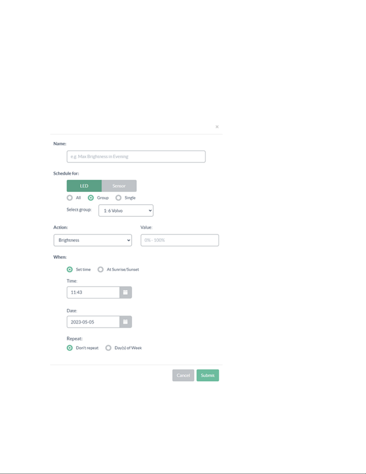
Schedule for a Group of LEDs
To add a schedule for a group of LEDs:
1. Select Scheduler from the main menu displayed on the right side of the Zum Outdoor LiteView
web page.
2. In the Select LED drop-down menu, select the target LED.
3. Select LED and Group under Schedule for.
4. Enter the schedule name, scheduling target, action, and time in the displayed screen.
5. Click Submit.
71 • ZUMNET-OD-GW-RF, ZUMMESH-OD-KOM, ZUMMESH-OD-7P Product Manual — Doc. 9376A
Page 72
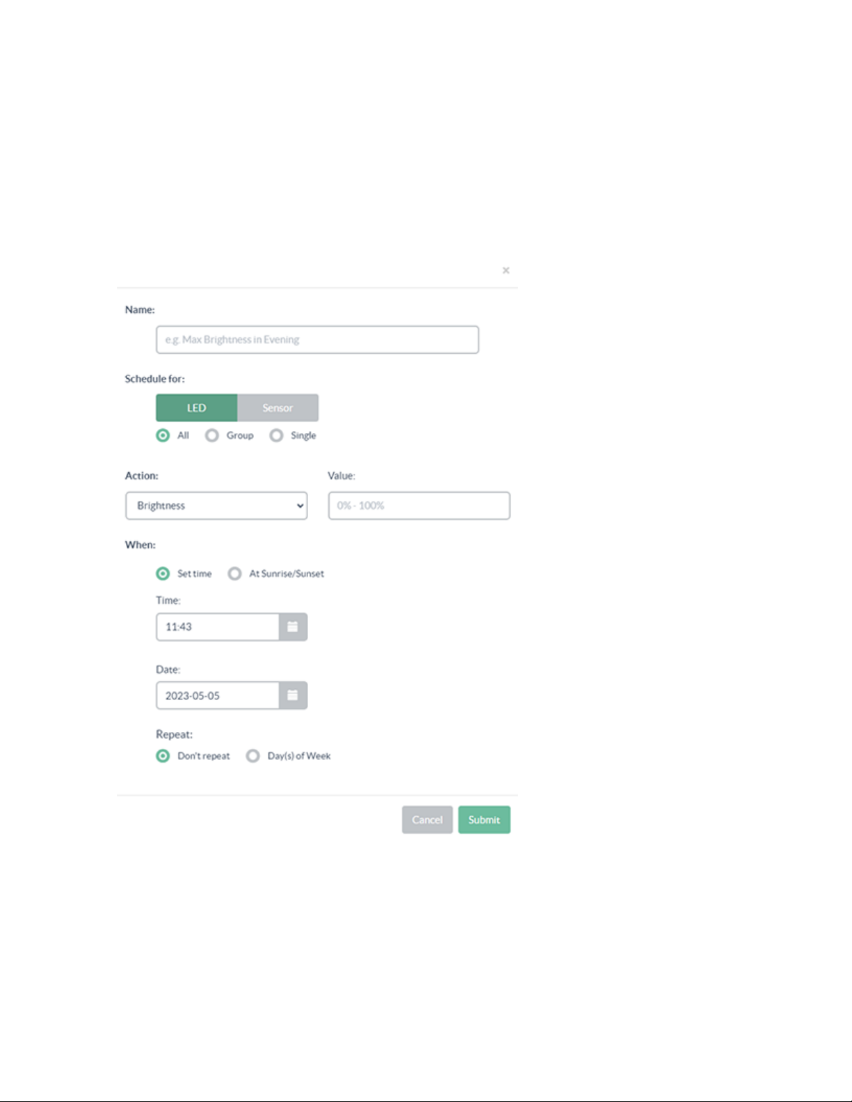
Add Schedule for all the LEDs
To schedule for all LEDs:
1. Select Scheduler from the main menu displayed on the right side of the Zum Outdoor LiteView
web page.
2. Select All under Schedule for for all the LEDs.
3. Enter the schedule name, scheduling target, action, and time in the displayed screen.
4. Click Submit.
Product Manual — Doc. 9376A ZUMNET-OD-GW-RF, ZUMMESH-OD-KOM, ZUMMESH-OD-7P • 72
Page 73
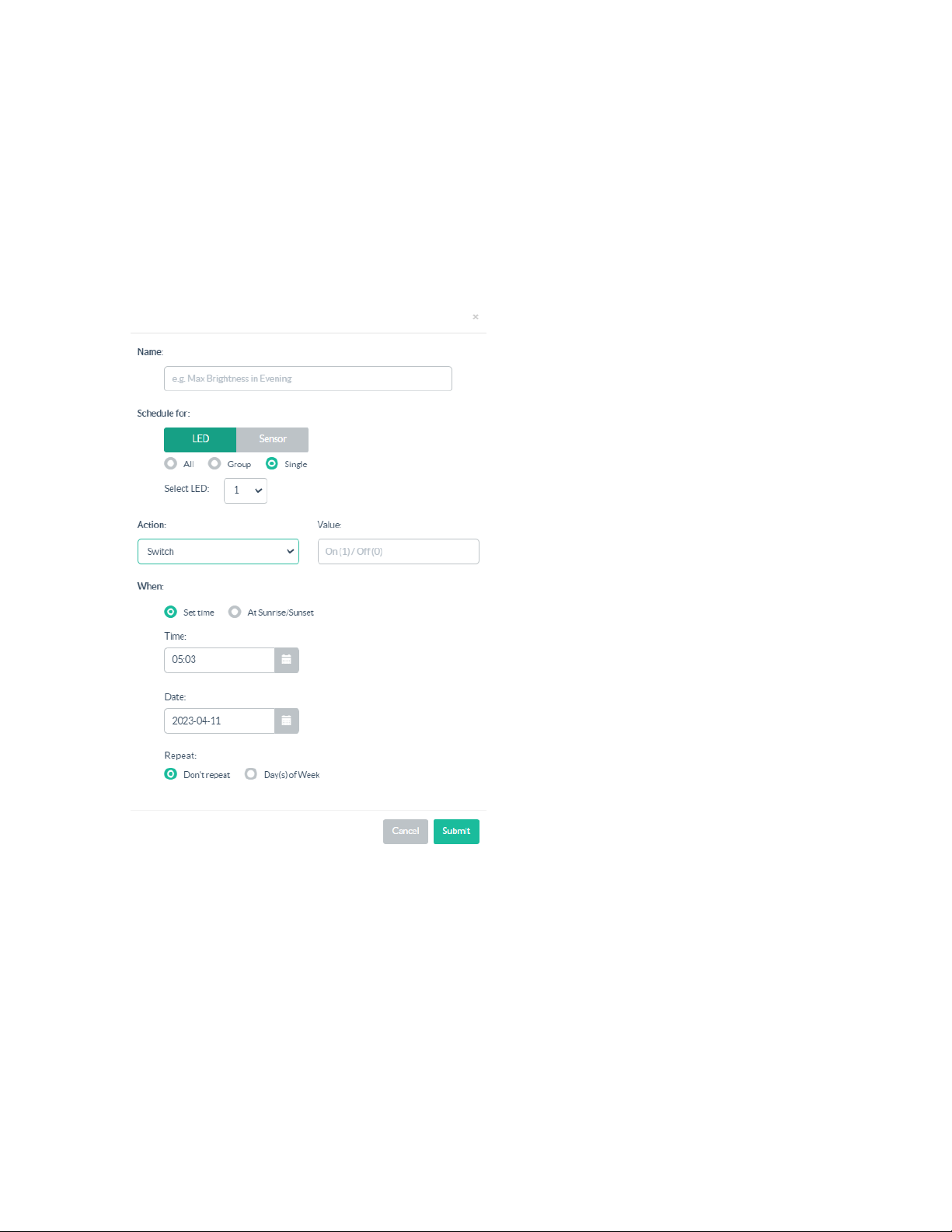
Schedule the On or Off Time Set Control for an LED
To schedule the on or off time set control for an LED:
1. Select Scheduler from the main menu displayed on the right side of the Zum Outdoor LiteView
web page.
2. Click Add Schedule.
3. Select Switch from the Action drop-down menu.
4. Enter a 0 or 1 in the Value text box to schedule Off or On time set for an LED. The values are 0 to
turn Off and 1 to turn On the LED.
73 • ZUMNET-OD-GW-RF, ZUMMESH-OD-KOM, ZUMMESH-OD-7P Product Manual — Doc. 9376A
Page 74
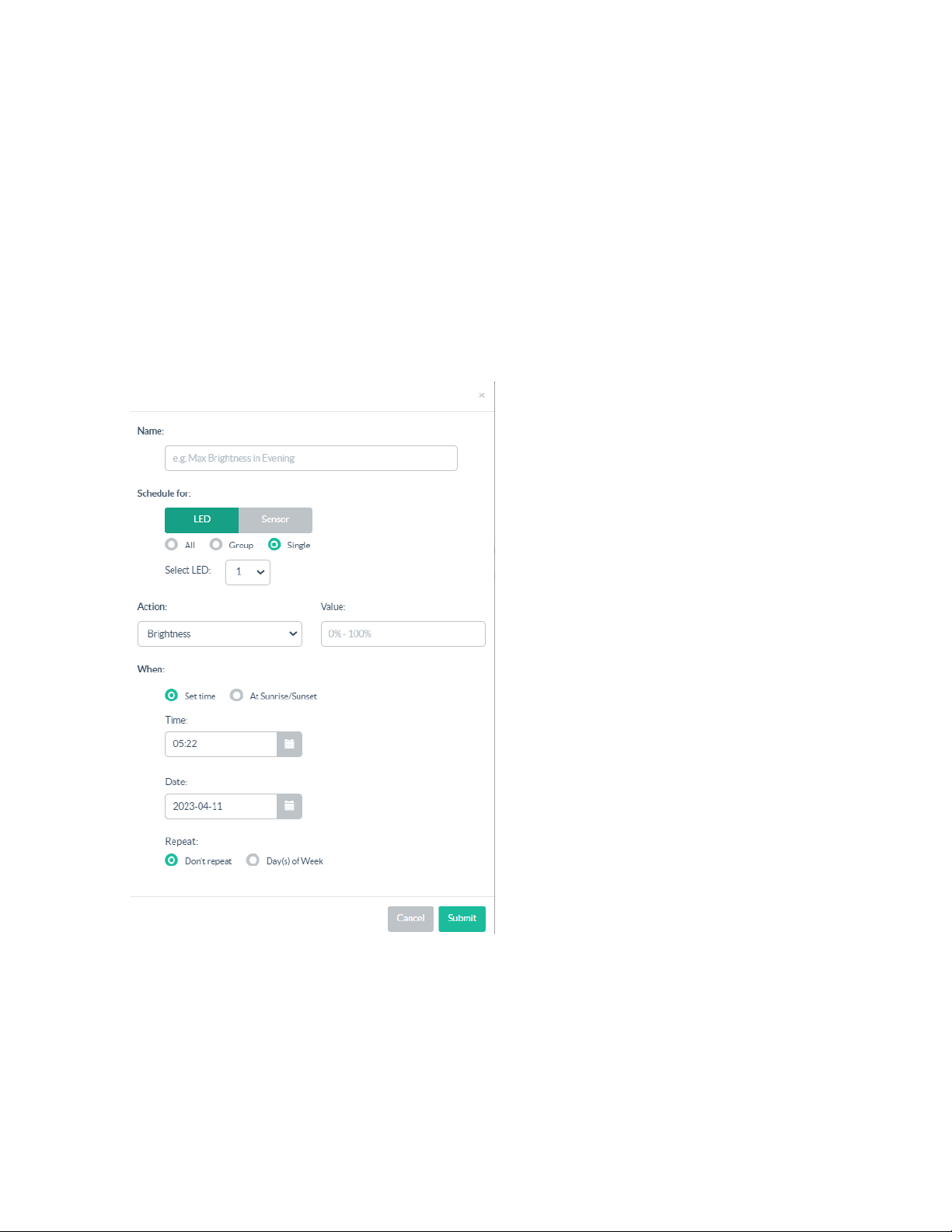
Schedule the Brightness Control
To schedule the brightness control:
1. Select Scheduler from the main menu displayed on the right side of the Zum Outdoor LiteView
web page.
2. Click Add Schedule.
3. Select Brightness in the Action drop-down menu.
4. Enter a number between 0-100 in the Value text box where 0% is the dimmest and 100% is the
highest value for brightness.
5. From the Time check box and Date check box, select a time and date to schedule the brightness
control.
6. Click Submit.
Product Manual — Doc. 9376A ZUMNET-OD-GW-RF, ZUMMESH-OD-KOM, ZUMMESH-OD-7P • 74
Page 75
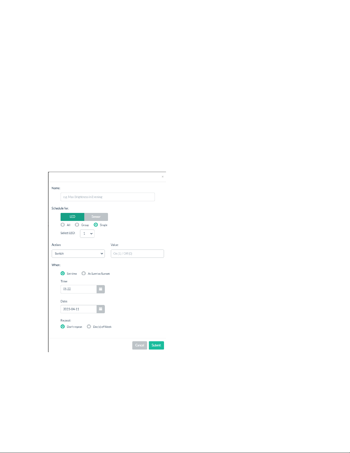
Set a Schedule for an LED to Turn On at a Specific Time and Date
To set a schedule for an LED to turn on at a specific time and date:
1. Select Scheduler from the main menu displayed on the right side of the Zum Outdoor LiteView
web page.
2. Click Add Schedule.
3. Select Brightness or Switch in the Action drop-down menu.
4. If Switch is selected, enter 1 to power On or 0 Power off the LED. If Brightness is selected, enter a
value between 0% and 100% for the brightness.
5. Select the Set time check box.
6. Set a time in the Time text box and select a date in the Date text box. The Don't Repeat can be
selected if the schedule is set for only one instance. Day(s) of Week can be selected depending on
whether the schedule needs to be run for a week or on specific days.
7. Click Submit.
75 • ZUMNET-OD-GW-RF, ZUMMESH-OD-KOM, ZUMMESH-OD-7P Product Manual — Doc. 9376A
Page 76
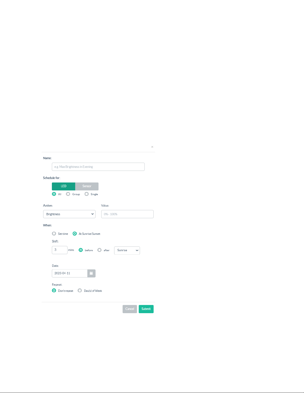
Set a Schedule for an LED to Turn On at Sunrise or Sunset
To set a for an LEDthat runs at sunrise or sunset:
1. Select Scheduler from the main menu displayed on the right side of the Zum Outdoor LiteView
web page.
2. Click Add Schedule.
3. Select Brightness or Switch from the Action drop-down menu.
4. If Switch is selected, enter 1 to power On or 0 Power off the LED. If Brightness is selected, enter a
value between 0% and 100% for the brightness.
5. Select At Sunrise or Sunset under When.
6. Fill in the offset time (in minutes) in the Shift text box, and choose before or after for sunrise or
sunset. The offset time will trigger the schedule before other routine schedules are triggered.
7. Click Submit.
Product Manual — Doc. 9376A ZUMNET-OD-GW-RF, ZUMMESH-OD-KOM, ZUMMESH-OD-7P • 76
Page 77
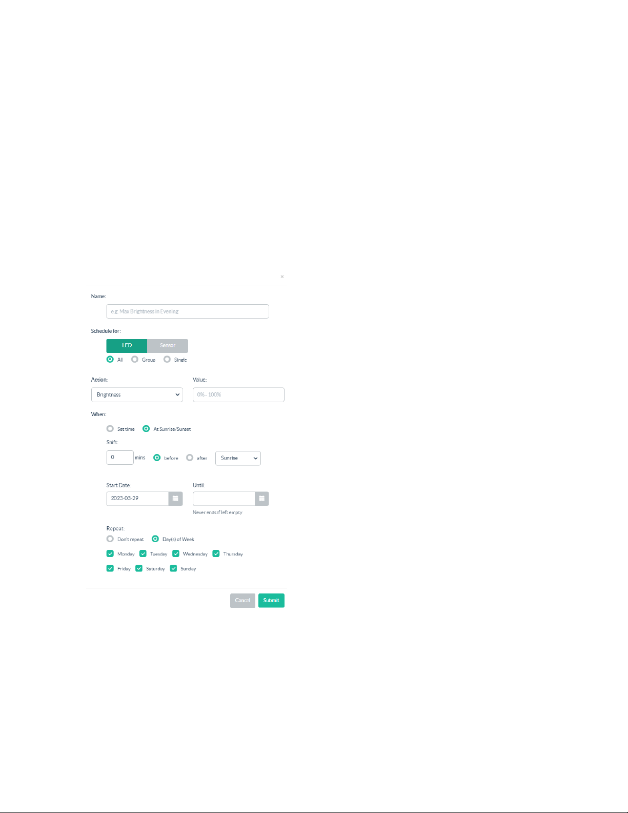
Set a Repeating Schedule for an LEDor Sensor
To set a repeating schedule for an LEDor Sensor:
1. Select Scheduler from the main menu displayed on the right side of the Zum Outdoor LiteView
web page.
2. Click Add Schedule.
3. Select Brightness or Switch from the Action drop-down menu.
4. If Switch is selected, enter 1 to power On or 0 Power off the LED. If Brightness is selected, enter a
value between 0% and 100% for the brightness.
5. Choose the day(s) of the week on which you want the schedule to repeat. The schedule will repeat
unless the date is set in the Until field.
6. Select Day(s) of Week under Repeat. The days in a week are displayed.
7. Click Submit.
77 • ZUMNET-OD-GW-RF, ZUMMESH-OD-KOM, ZUMMESH-OD-7P Product Manual — Doc. 9376A
Page 78
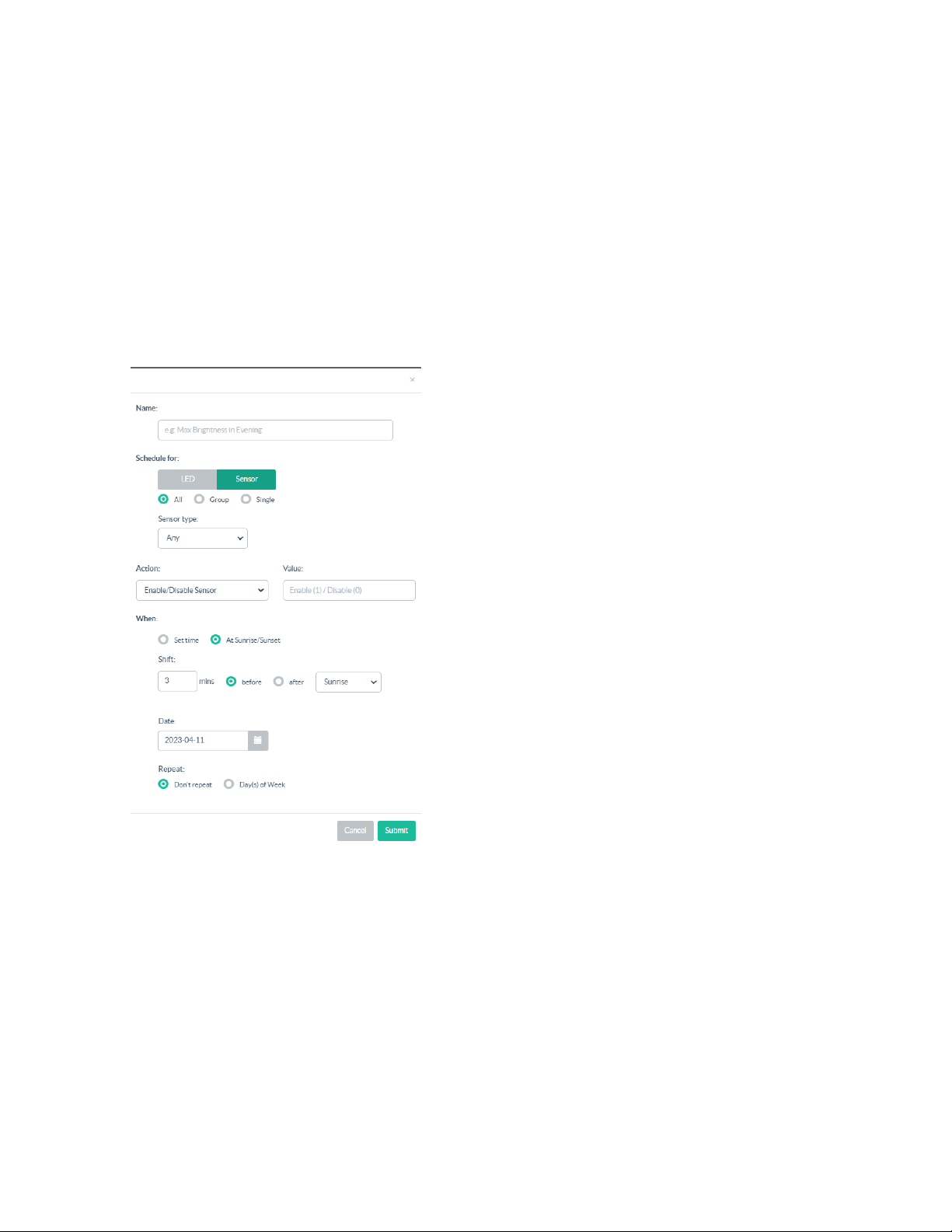
Set a Schedule for the Sensors
To set a schedule for the sensors:
1. Select Scheduler from the main menu displayed on the right side of the Zum Outdoor LiteView
web page.
2. Click Add Schedule.
3. Select Sensor under Schedule for.
4. In the Sensor Type drop-down menu, select the corresponding sensor type.
5. In the Action drop-down menu, select Enable/Disable Sensor.
6. Enter 0 or 1 in the Value text box where 1 is to enable and 0 is to disable a sensor.
7. Click Submit.
Product Manual — Doc. 9376A ZUMNET-OD-GW-RF, ZUMMESH-OD-KOM, ZUMMESH-OD-7P • 78
Page 79
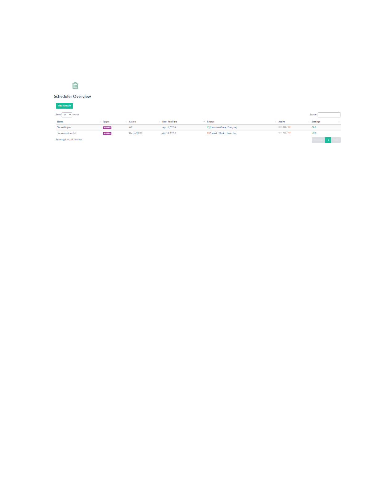
Delete a Schedule
To delete a schedule:
1. Select Scheduler from the main menu displayed on the right side of the Zum Outdoor LiteView
web page.
2.
Select Delete in the row to delete a schedule that is not needed.
3. In the confirmation window, select Remove Schedule.
79 • ZUMNET-OD-GW-RF, ZUMMESH-OD-KOM, ZUMMESH-OD-7P Product Manual — Doc. 9376A
Page 80
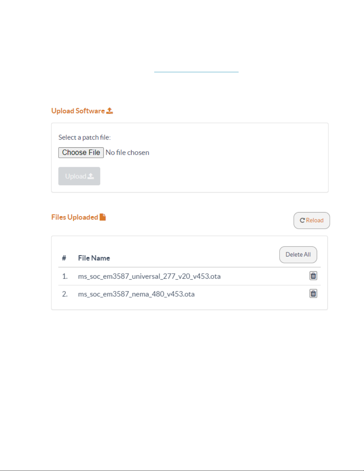
Update Software
To update software:
1. Download the latest firmware from www.crestron.com/firmware to a computer.
2. Go to Settings > Gateway Settings.
3. In Update Software, select Choose File and then select the firmware file.
4. Select Upload.
5. The Files Uploaded screen is displayed.
Product Manual — Doc. 9376A ZUMNET-OD-GW-RF, ZUMMESH-OD-KOM, ZUMMESH-OD-7P • 80
Page 81

Resources
The following resources are provided for the ZUMNET-OD-GW-RF, ZUMMESH-OD-KOM,
ZUMMESH-OD-7P.
NOTE:You may need to provide your Crestron.com web account credentials when prompted to
access some of the following resources.
Crestron Support and Training
l
Crestron True Blue Support
l
Crestron Resource Library
l
Crestron Online Help (OLH)
l
Crestron Training Institute (CTI)Portal
Programmer and Developer Resources
l
help.crestron.com:Provides help files for Crestron programming tools such as SIMPL, SIMPL#,
and Crestron Toolbox™ software
l
developer.crestron.com:Provides developer documentation for Crestron APIs, SDKs, and other
development tools
Product Certificates
To search for product certificates, refer to support.crestron.com/app/certificates.
81 • ZUMNET-OD-GW-RF, ZUMMESH-OD-KOM, ZUMMESH-OD-7P Product Manual — Doc. 9376A
Page 82

Crestron Electronics, Inc.
15 Volvo Drive, Rockleigh, NJ 07647
Tel: 888.CRESTRON
Fax: 201.767.7656
www.crestron.com
Product Manual — Doc. 9376A
05/05/23
Specifications subject to
change without notice.
 Loading...