

Page 1

Crestron Isys® TPS-12/15/17
Tilt Touchpanels
Operations Guide
Page 2

This document was prepared and written by the Technical Documentation department at:
Crestron Electronics, Inc.
15 Volvo Drive
Rockleigh, NJ 07647
1-888-CRESTRON
All brand names, product names and trademarks are the property of their respective owners.
©2005 Crestron Electronics, Inc
Page 3

Crestron Isys® TPS-12/15/17 Tilt Touchpanels
Contents
Crestron Isys® Tilt Touchpanels: TPS-12/15/17 1
Introduction ........................................................................................................................1
Features and Functions .............................................................................................................. 1
Specifications ............................................................................................................................3
Physical Description.................................................................................................................. 5
Tilt Angle Tension Adjustment ............................................................................................... 14
Industry Compliance................................................................................................................ 14
Setup.................................................................................................................................14
Network Wiring....................................................................................................................... 14
QuickMedia Network Wiring.................................................................................................. 15
Identity Code ........................................................................................................................... 16
Configuring the Touchpanel.................................................................................................... 16
Hardware Hookup.................................................................................................................... 24
Recommended Cleaning.......................................................................................................... 26
Programming Software.....................................................................................................27
Earliest Version Software Requirements for the PC................................................................ 28
Programming with Crestron System Builder........................................................................... 28
Programming with SIMPL Windows ......................................................................................29
Programming with VisionTools Pro-e..................................................................................... 31
Hard Button Programming ......................................................................................................34
Reserved Join Numbers...........................................................................................................34
MultiByte International Characters..........................................................................................42
Uploading and Upgrading.................................................................................................43
Establishing Communications ................................................................................................. 43
Troubleshooting Communications........................................................................................... 52
Uploading a SIMPL Windows Program .................................................................................. 52
Uploading a VT Pro-e Project .................................................................................................54
Firmware Upgrade................................................................................................................... 56
Problem Solving ...............................................................................................................59
Troubleshooting....................................................................................................................... 59
Further Inquiries ...................................................................................................................... 60
Future Updates......................................................................................................................... 60
Software License Agreement............................................................................................61
Return and Warranty Policies........................................................................................... 63
Merchandise Returns / Repair Service..................................................................................... 63
CRESTRON Limited Warranty............................................................................................... 63
Operations Guide – DOC. 6375 Contents •
i
Page 4

Page 5

Crestron Isys® TPS-12/15/17 Tilt Touchpanels
Crestron Isys® Tilt Touchpanels:
TPS-12/15/17
Introduction
Features and Functions
The Crestron Isys® TPS-12, TPS-15 and TPS-17 family of tilt touchpanels offer high
brightness and contrast combined with a super wide viewing angle to deliver crisp,
detailed images under all conditions. For simplicity within this guide, these
touchpanels are referred to as TPS-12/15/17, except where noted. These touchpanels
are QuickMedia™ compatible. The features and specifications for all three
touchpanels are identical (except those relating to the screen). The touchpanels are
available with a variety of color bezels (ex. black with silver accent, white with gray
accent), and are designated with a -B or -W respectively.
Functional Summary
• 12, 15, and 17 inch (widescreen) active matrix color displays
• Screen resolutions: TPS-12 800 x 600, TPS-15 1024 x 768,
TPS-17 1280 x 768
• 16.7 million colors, 24-bit graphics with 8-bit alpha channel
• 128 MB of DDR RAM, 32 MB of internal flash (expandable to
160 MB)
• Built-in time-based correction for stable video and graphics
• Supports composite, S-video, and component inputs in both NTSC and
PAL formats
• Supports QuickMedia™ transport technology, which affords expanded
AV connectivity through a streamlined wiring solution
• Supports Crestron Home
• Full screen video capability
• Up to 4,000 digital and analog signals; up to 999 serial signals
• Built-in microphone and biamplified speaker system
• Built-in audio amplifier, 5 W per channel
• Stores and plays back WAV sound files
• Stereo headphone jack
• Stereo audio input and microphone output
• 10BaseT/100BaseTX high-speed Ethernet, 802.3U compliant, full
duplex, auto switching
• Five backlit hard buttons (one reset and four programmable buttons)
•
®
CAT5 balanced AV connectivity
-
-
Operations Guide – DOC. 6375 Tilt Touchpanels: TPS-12/15/17 ¥
1
Page 6
Tilt Touchpanels Crestron Isys® TPS-12/15/17
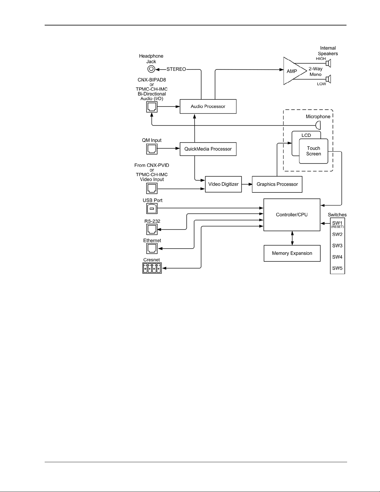
TPS-12/15/17 Block Diagram
Memory
The TPS-12/15/17 touchpanels feature 128 MB DDR RAM and 32 MB Flash, with a
built-in compact flash slot that allows flash memory expansion up to 160 MB.
Sound
Audio capabilities include 5 Watts per channel biamplified audio speakers that offer
built-in volume control, a built-in microphone and built-in WAV sound file
capability. Sound can be generated by the panel by using downloaded wave files
(.WAV) or can be mixed in from an external line level audio source or a QuickMedia
input. The TPS-12/15/17 touchpanels are also equipped with balanced output for
microphone audio that can be connected to a Crestron CNX-BIPAD8 or similar
Crestron CAT5 audio receiver.
Video
The TPS-12/15/17 touchpanels can display a single video window per page, and use
auto-detect for composite, S-video, component, NTSC and PAL formats. These
touchpanels support SDTV formats (does not support HD). Two video inputs
provide for connectivity to QuickMedia and PVID video distribution switches
(CNX-PVID8X3 or CNX-PVID8X4).
¥ Tilt Touchpanels: TPS-12/15/17 Operations Guide – DOC. 6375
2
Page 7

Crestron Isys® TPS-12/15/17 Tilt Touchpanels
QuickMedia™
While acting as a QuickMedia (QM) receiver, the TPS-12/15/17 touchpanels can be
connected as an endpoint to a QM switching device or QM transmitter.
NOTE: The TPS-12/15/17 does not support RGB.
Connectivity
The TPS-12/15/17 touchpanels feature a Cresnet and a high-speed Ethernet port for
seamless communication with Crestron control systems, and computers. In addition,
a USB port is provided for future applications. The "RS-232 Port for Touch Output"
operation transmits touch coordinates to external devices via RS-232 for “TouchThe-PC” and other functions.
Specifications
The following table provides a summary of specifications for the TPS-12/15/17.
TPS-12/15/17 Specifications
SPECIFICATION DETAILS
Cresnet® Power Usage
Not including
TPMC-CH-IMC (1.0 W)
TPS-12 43 W (1.8 A @ 24 V) Supplied via NET port
TPS-15 65 W (2.7 A @ 24 V) Supplied via NET port
TPS-17 74 W (3.08 A @ 24 V) Supplied via NET port
Default Net ID 03
Timeout Adjustable from 0 to 120 minutes (Default = 10 min.)
Signal Join Maximums 4000 Digital, 4000 Analog, 999 Serial
Control System Update
1, 2, 3
Files
2-Series Control System
Touchpanel Firmware tps-12_tps-15_tps-17_1.xxx.xxxx.csf
Memory
Memory Expansion
Video
Audio
Version 3.137.CUZ or later
32 MB Flash, 128 MB DDR RAM
Up to 160 MB via Compact Flash
Full screen capable, standard definition formats
Auto detect of composite, S-video, component, NTSC, and PAL
16.7M colors
Time base correction & gamma correction
Supports 480i component video and 576i formats
Built-in microphone
Two built-in biamplified speakers (5 W per channel)
Stereo headphone output
Internal volume control and audio mixer
WAV file capability (8-bit PCM)
Continued on the following page
Operations Guide – DOC. 6375 Tilt Touchpanels: TPS-12/15/17 ¥
3
Page 8

Tilt Touchpanels Crestron Isys® TPS-12/15/17
TPS-12/15/17 Specifications (continued)
SPECIFICATION DETAILS
Connectors
NET One 4-pin 5 mm detachable terminal block for connection to
USB One USB port (reserved for future applications)
RS-232 One 6-pin RJ-11 female connector, bi-directional RS-232 serial
Headphones One 3.5 mm stereo TRS mini phone jack, output power 12 mW,
QM IN One RJ-45 QuickMedia input connector
VIDEO IN One RJ-45 CNX-PVID differential video input connector
AUDIO I/O One RJ-45 CNX-BIPAD balanced stereo audio input and
LAN One 8-wire RJ-45 Ethernet port with link/activity LED indicators,
Buttons Five illuminated pushbuttons, the leftmost button (SW1) is
Display
Type Active Matrix Color LCD
Aspect Ratio TPS-12 4:3
Resolution TPS-12 800 x 600
Brightness TPS-12 400 nits
Contrast TPS-12 300:1
Illumination Backlit fluorescent
Viewing Angle TPS-12 +/- 70 degrees horizontal, +45/-55 degrees vertical
Tilt Angle 45 to 90 degrees
Enclosure Metal enclosure with a molded plastic bezel and integral rear
Cresnet
connection, touchscreen output to PC or telestrator, or serial
mouse connection
impedance 32 Ohms (nominal)
microphone output connector
10BaseT/100BaseTX high-speed Ethernet, TCP/IP, UDP/IP, CIP,
DHCP, 802.3U compliant, full duplex, auto switching
recessed and is a hardware reset used to reboot the touchpanel,
the four other buttons are user programmable
TPS-15 4:3
TPS-17 15:9
TPS-15 1024 x 768
TPS-17 1280 x 768
TPS-15 400 nits
TPS-17 450 nits
TPS-15 300:1
TPS-17 400:1
TPS-15 +/- 85 degrees horizontal and vertical
TPS-17 +/- 88 degrees horizontal and vertical
cover and cable strain relief
CPU 32-bit Motorola Coldfire
Processing Speed 410 MIPS
Operating Environment Temperature: 41° to 113°F (5° to 45°C)
Humidity: 10% to 90% RH (non-condensing)
Continued on the following page
¥ Tilt Touchpanels: TPS-12/15/17 Operations Guide – DOC. 6375
4
Page 9

Crestron Isys® TPS-12/15/17 Tilt Touchpanels
TPS-12/15/17 Specifications (continued)
SPECIFICATION DETAILS
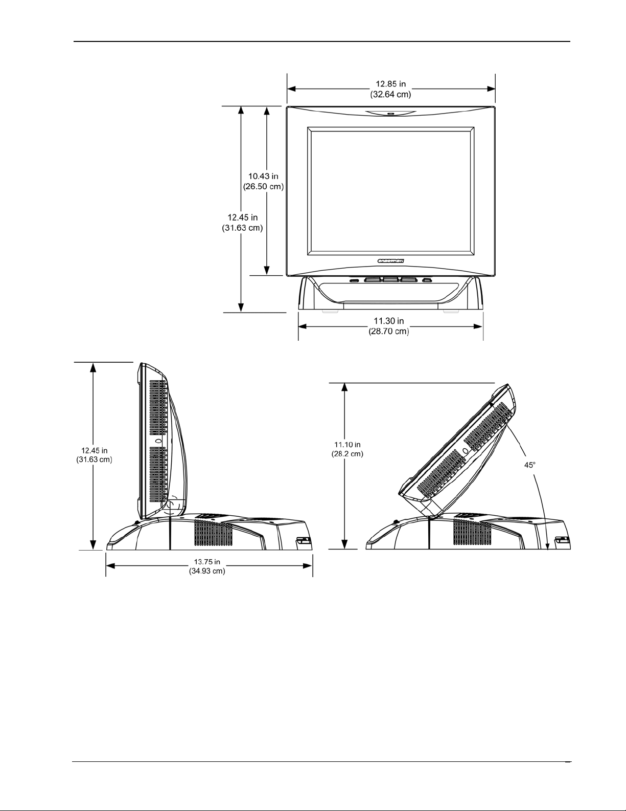
TPS-12 Dimensions Height: 12.45 in (31.63 cm)
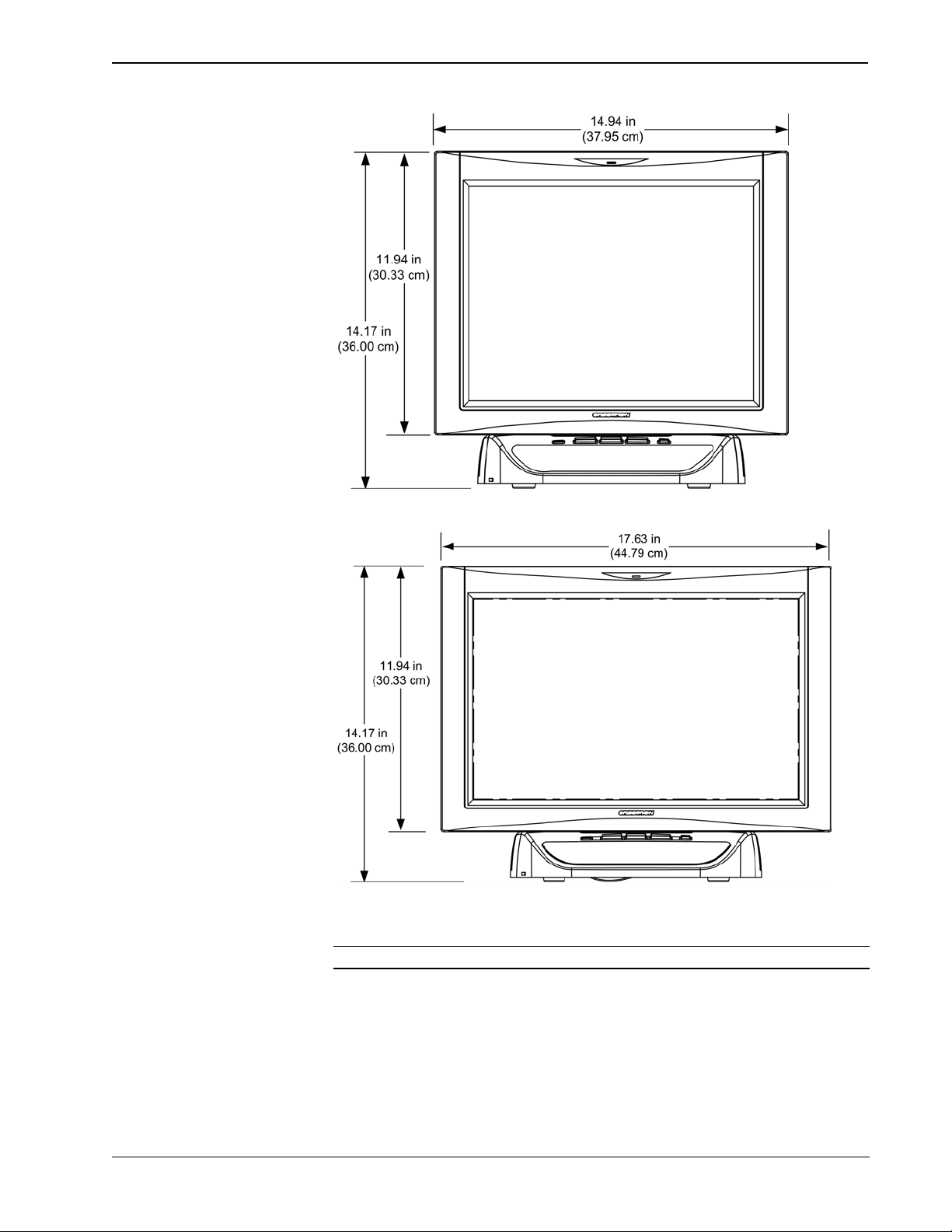
TPS-15 Dimensions Height: 14.17 in (36.00 cm)
TPS-17 Dimensions Height: 14.17 in (36.00 cm)
Accessories TPMC-CH-IMC interface unit
1 The latest software versions can be obtained from the Crestron website. Refer to the NOTE
following these footnotes.
2 Crestron 2-Series control systems include the AV2 and PRO2. Consult the latest Crestron Product
Catalog for a complete list of 2-Series control systems.
3 When loading VT Pro-e files or firmware through the RS-232 port of the control system, be sure that
the baud rate is at 38400 (Cresnet speed) or lower. Otherwise, Toolbox may post the “Transfer
Failed” message.
Width: 12.85 in (32.64cm)
Depth: 13.75 in (34.93 cm)
Weight: 12.95 lbs (5.88 kg)
Width: 14.94 in (37.95 cm)
Depth: 13.75 in (34.93 cm)
Weight: 14.55 lbs (6.60 kg)
Width: 17.63 in (44.79 cm)
Depth: 13.75 in (34.93)
Weight: 18.10 lbs (8.21 kg)
NOTE: Crestron software and any files on the website are for authorized Crestron
dealers and Crestron Authorized Independent Programmers (CAIP) only. New users
may be required to register to obtain access to certain areas of the site (including the
FTP site).
Physical Description
The electronic hardware is housed in a metal enclosure with a molded plastic bezel,
which is available in a variety of colors such as black with silver accent or white
with gray accent. This touchpanel is designed for placement on a tabletop or other
flat surface. All audio, RS-232, video, and network connections are made at the rear
panel on the base of the unit. A grille located on the front base of the unit conceals a
high frequency speaker; the low frequency speaker is in the base. The microphone is
located at the top center above the touchscreen. Five buttons (one reset and four
programmable) are located on the base.
Operations Guide – DOC. 6375 Tilt Touchpanels: TPS-12/15/17 ¥
5
Page 10
Tilt Touchpanels Crestron Isys® TPS-12/15/17
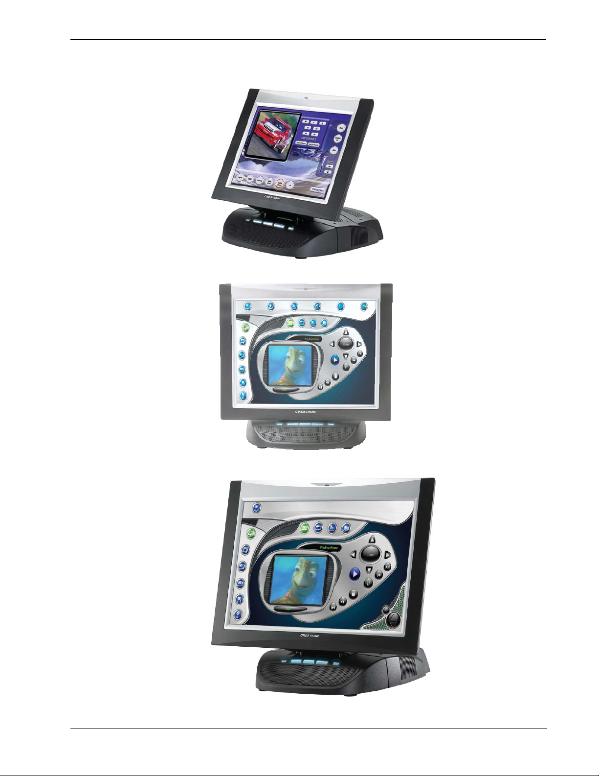
TPS-12 Angled View
TPS-15 Front View
TPS-17 Angled View
¥ Tilt Touchpanels: TPS-12/15/17 Operations Guide – DOC. 6375
6
Page 11
Crestron Isys® TPS-12/15/17 Tilt Touchpanels
TPS-12 Physical View – Front
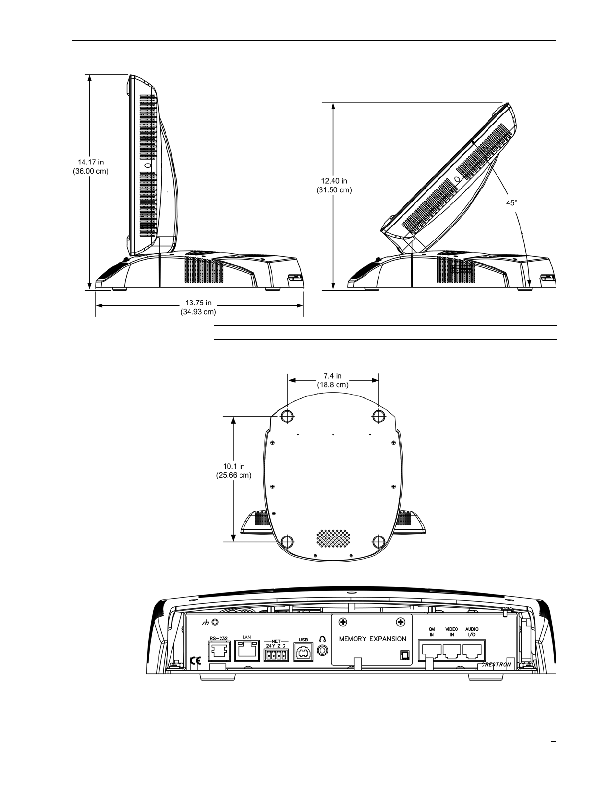
TPS-12 Physical Views – Side View at Maximum and Minimum Elevation
Operations Guide – DOC. 6375 Tilt Touchpanels: TPS-12/15/17 ¥
7
Page 12
Tilt Touchpanels Crestron Isys® TPS-12/15/17
TPS-15 Physical View – Front
TPS-17 Physical View – Front
NOTE: The TPS-15 and TPS-17 are the same height.
¥ Tilt Touchpanels: TPS-12/15/17 Operations Guide – DOC. 6375
8
Page 13
Crestron Isys® TPS-12/15/17 Tilt Touchpanels
TPS-15 and TPS-17 Physical Views – Side View at Maximum and Minimum Elevation
NOTE: All three touchpanels share an identical base unit.
Bottom View
View of Rear Connectors – Cover Removed
Operations Guide – DOC. 6375 Tilt Touchpanels: TPS-12/15/17 ¥
9
Page 14
Tilt Touchpanels Crestron Isys® TPS-12/15/17
Ports and Pushbuttons
All connections to the TPS-12/15/17 are made through the ports on the rear panel.
Refer to the illustrations and descriptions that follow.
NOTE: Rear ports are not accessible after the cover is replaced.
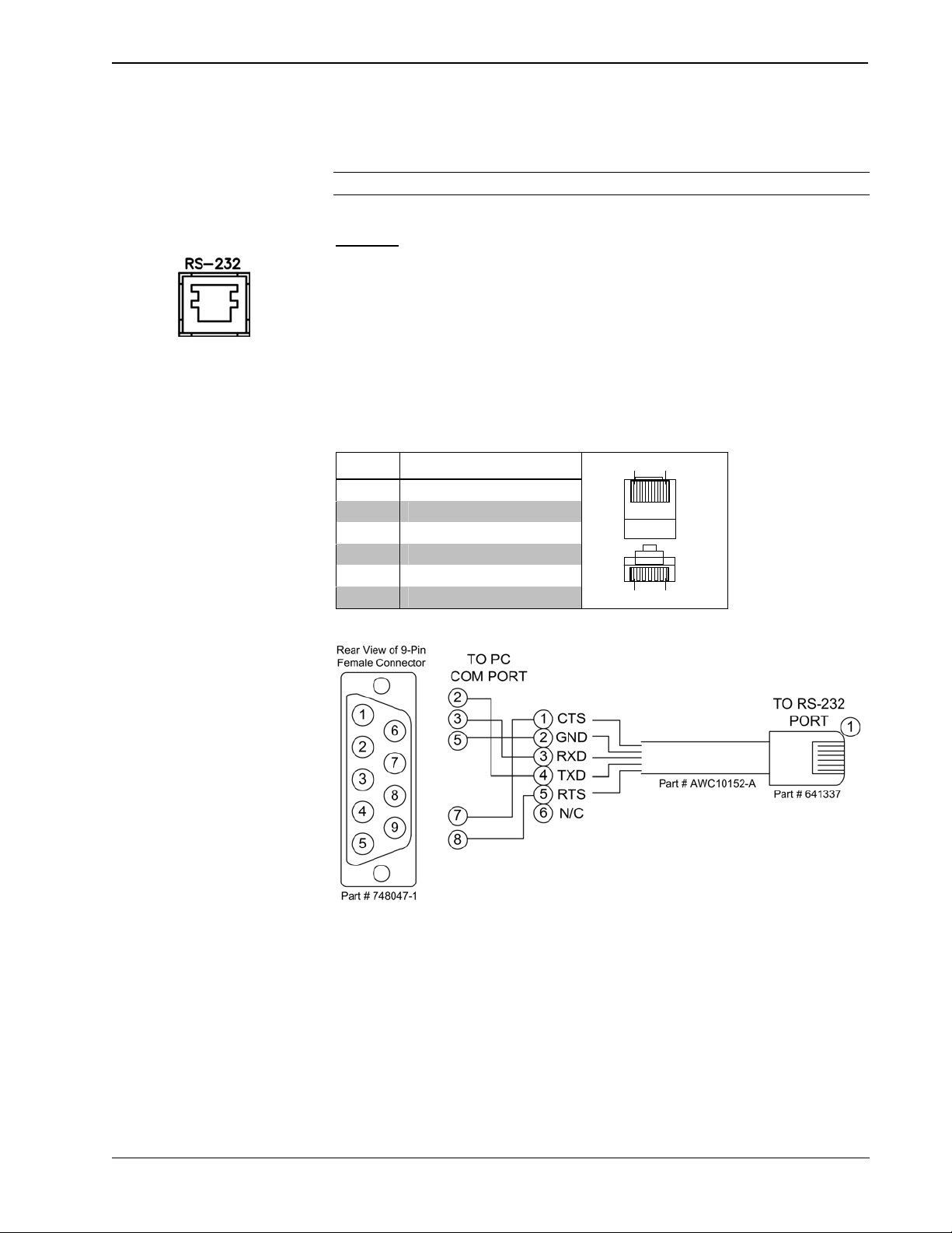
RS-232
This 6-pin RJ-11 connector mates with a 9-pin serial port of a PC. The connecting
cable is not supplied. Use this port to establish a direct connection between the
touchpanel and a PC without a control system or network connection. Once the direct
connection is established, touchpanel files and firmware updates can be uploaded to
the touchpanel. Additionally, the touchpanel’s diagnostic tools can be accessed over
the direct connection. In the event that modular cables or an RJ-11 to DB9F adapter
is not available, the following table and diagram provide information so that the cable
can be fabricated on site. Refer to “RS-232 Menu” on page 20 for RS-232 port
configuration settings.
RS-232 Pinouts
Top
Front
16
6
1
PIN # DESCRIPTION
1 CTS
2 GND
3 RXD
4 TXD
5 RTS
6 N/C (Not connected)
PC to TPS-12/15/17 Cable Specifications (Crestron Cable Number STCP-502PC)
¥ Tilt Touchpanels: TPS-12/15/17 Operations Guide – DOC. 6375
10
Page 15
Crestron Isys® TPS-12/15/17 Tilt Touchpanels
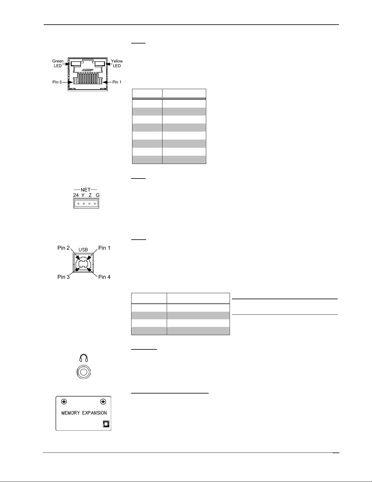
LAN
LAN
One 8-wire RJ-45 connector with two LED indicators (green LED indicates link
status, yellow LED indicates Ethernet activity). This connector provides an Ethernet
10baseT /100baseTX, full duplex, TCP/IP, UDP/IP, CIP, DHCP, IEEE 802.3U
compliant network connection.
Network Connector Pinout
PIN SIGNALS
1 TX +
2 TX -
3 RC+
4 N/C
5 N/C
6 RC -
7 N/C
8 N/C
NET
The four-pin 5 mm detachable terminal block provides communication with and
power from a Cresnet control network. For additional details, refer to “Network
Wiring” on page 14. A cable for this connection is provided with the touchpanel.
Pins 24 and G provide 24 VDC and ground.
Pins Y and Z provide communications (data).
USB
One Universal Serial Bus (USB) “B” connector provides a communications link.
USB is a connectivity specification developed by the USB Implementers Forum
that provides a single, simple, standardized way to connect devices to a computer.
USB shielded cables contain two wires for power +5 volts (red) and ground
(brown) and a twisted pair of wires (yellow and blue) that carry data.
USB Type B Connector Pinout
PIN DESCRIPTION
1 +5 VDC
2 Data -
3 Data +
4 Ground
NOTE: This connector is reserved for
future applications.
PHONE
Connect this standard mini phone jack (12 mW, 32 ohm load) to the plug of a 3.5
mm external headphone set plug (not supplied). Plugging in the headphone cuts off
the speakers.
MEMORY EXPANSION
The onboard memory may be enhanced with the addition of a Type II compact flash
memory (up to 160 MB).
The flash memory slot is accessible on the rear panel of the unit.
Operations Guide – DOC. 6375 Tilt Touchpanels: TPS-12/15/17 ¥
11
Page 16
Tilt Touchpanels Crestron Isys® TPS-12/15/17
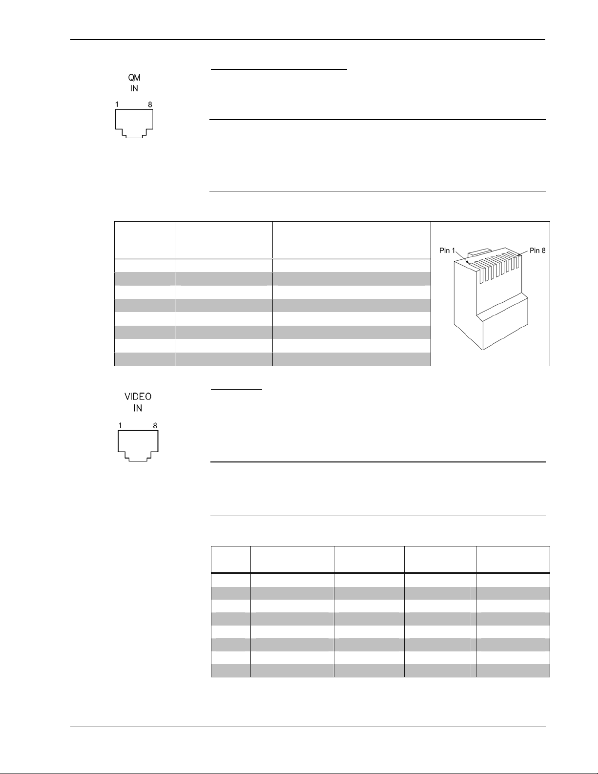
QM IN (QuickMedia Input)
The eight-pin RJ-45 QuickMedia transport port accepts Crestron Certified Wiring
carrying audio, video, and microphone signals. The QM input port conforms to the
568B wiring standard. Refer to the following table for connector pinouts.
NOTE: The QM port is not connected through any “IMC” interface.
NOTE: Only one video source may be displayed at a time.
NOTE: These touchpanels do not support RGB.
RJ-45 QuickMedia Connector Pin Assignments
RJ-45 PIN
NUMBER
1 WHITE/ORANGE - CHROMINANCE (- PR)
2 ORANGE + CHROMINANCE (+ PR)
3 WHITE/GREEN - LUMINANCE (- Y)
4 BLUE + AUDIO
5 WHITE/BLUE - AUDIO
6 GREEN + LUMINANCE (+ Y)
7 WHITE/BROWN - COMPOSITE (- PB)
8 BROWN + COMPOSITE (+ PB)
WIRE COLORS
(EIA 568B)
QM ASSIGNMENT COMPOSITE,
S-VIDEO, COMPONENT AND
VIDEO IN
This eight-pin RJ-45 connection provides connectivity to the CNX-PVID or the
TPMC-CH-IMC interface module. This port provides component, composite or
S-video balanced input to the touchpanel over Crestron Certified Wiring. Description
of the pinouts is shown in the following table. A cable for this connection is provided
with the touchpanel.
CAUTION: Only use the TPMC-CH-IMC Interface Module when connecting this
port. Use of other “IMC” products could damage the panel.
RJ-45 MALE CONNECTOR
AUDIO
NOTE: Only one video source may be displayed at a time.
Video In Pin Assignments
PIN WIRE COLORS
(568B)
1 WHITE/ORANGE + Composite + Luminance + Y
2 ORANGE - Composite - Luminance - Y
3 WHITE/GREEN N/A + Chrominance + PB
4 BLUE N/A N/A + PR
5 WHITE/BLUE N/A N/A - PR
6 GREEN N/A - Chrominance - PB
7 WHITE/BROWN N/A N/A N/A
8 BROWN N/A N/A N/A
¥ Tilt Touchpanels: TPS-12/15/17 Operations Guide – DOC. 6375
12
COMPOSITE S-VIDEO COMPONENT
Page 17
Crestron Isys® TPS-12/15/17 Tilt Touchpanels
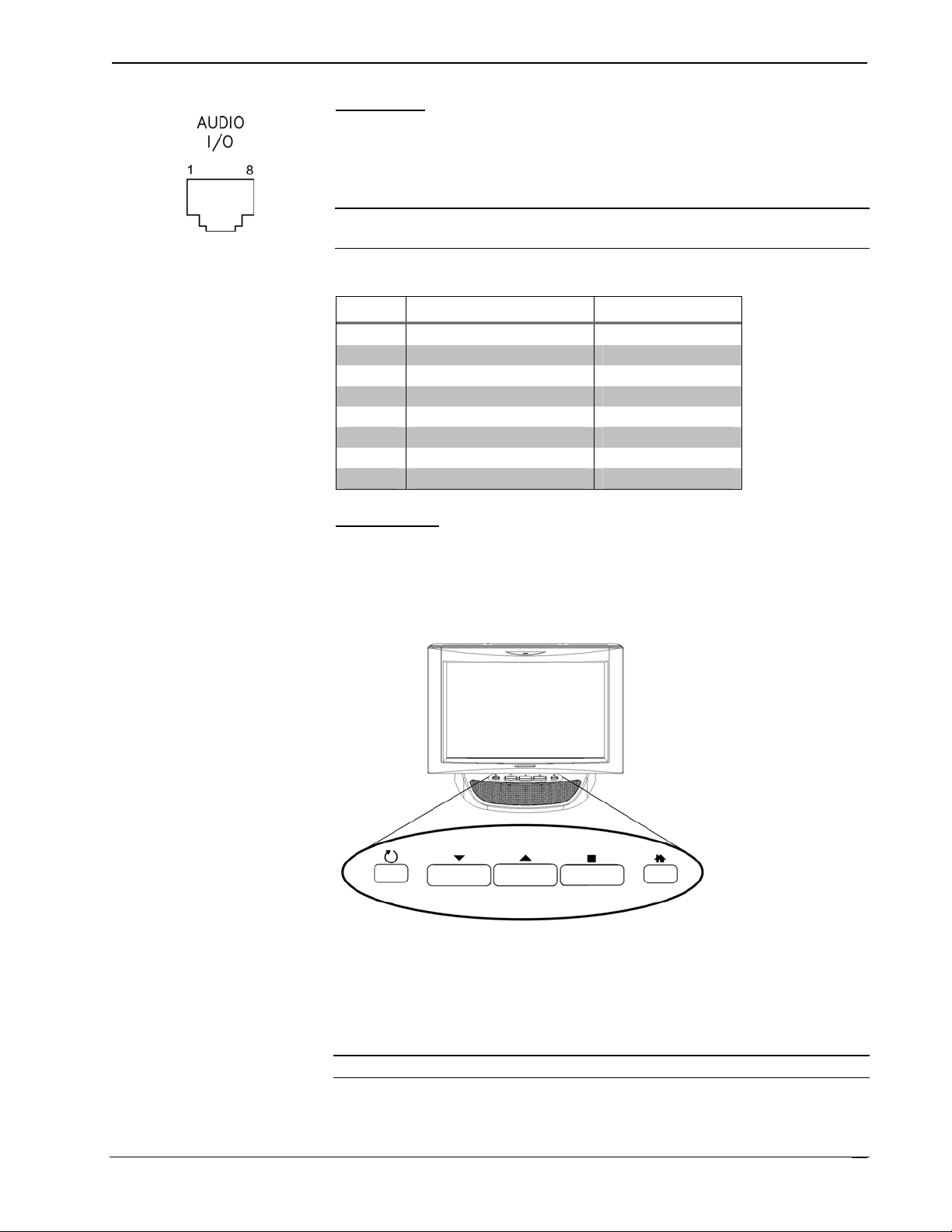
AUDIO I/O
This 8-pin RJ-45 connector provides connectivity to the CNX-BIPAD or with the
TPMC-CH-IMC interface module. This port uses Crestron Certified Wiring and
provides audio input to the touchpanel and microphone output from the touchpanel.
A description of the pinouts is shown in the following table.
CAUTION: Only use the TPMC-CH-IMC Interface Module when connecting this
port. Use of other “IMC” products could damage the panel.
Audio In/Out Pin Assignments
PIN WIRE COLORS (568B) AUDIO I/O
1 WHITE/ORANGE + Mic Left Out
2 ORANGE - Mic Left Out
3 WHITE/GREEN + Mic Right Out
4 BLUE + Audio Left In
5 WHITE/BLUE - Audio Left In
6 GREEN - Mic Right Out
7 WHITE/BROWN + Audio Right In
8 BROWN - Audio Right In
Pushbuttons
Five pushbuttons are located on the top of the base as shown in the following
diagram. The leftmost button is recessed and is a hard reset used to reboot the
touchpanel. The other four buttons are programmable. Refer to page 34 for hard
button programming information.
TPS-12/15/17 Pushbuttons
TPMC-CH-IMC Interface Module
For networks without CAT5 audio and video, the TPMC-CH-IMC is included to
convert unbalanced video sent over coax cable and balanced/unbalanced audio sent
over shielded, twisted-pair wiring to Crestron Certified Wiring for connection to the
touchpanels.
NOTE: The TPMC-CH-IMC is not for use with QuickMedia.
Operations Guide – DOC. 6375 Tilt Touchpanels: TPS-12/15/17 ¥
13
Page 18

Tilt Touchpanels Crestron Isys® TPS-12/15/17
Tilt Angle Tension Adjustment
Use a 5/32 inch socket (supplied by other) with a hex drive key (Allen wrench) to
increase or decrease pivot tension at the base of the touchscreen. Turning the key
clockwise increases tension, counterclockwise decreases tension.
Tension Adjustment Screw
Setup
Industry Compliance
As of the date of manufacture, the TPS-12, TPS-15, and TPS-17 have been tested
and found to comply with specifications for CE marking and standards per EMC and
Radiocommunications Compliance Labelling.
NOTE: This device complies with part 15 of the FCC rules. Operation is subject to
the following two conditions: (1) this device may not cause harmful interference, and
(2) this device must accept any interference received, including interference that may
cause undesired operation.
Network Wiring
CAUTION: In order to ensure optimum performance over the full range of your
installation topology, Crestron Certified Wire, and only Crestron Certified Wire, may
be used. Failure to do so may incur additional charges if support is required to
identify performance deficiencies as a result of using improper wire.
CAUTION: Use only Crestron power supplies for Crestron equipment. Failure to
do so could cause equipment damage or void the Crestron warranty.
¥ Tilt Touchpanels: TPS-12/15/17 Operations Guide – DOC. 6375
14
Page 19
Crestron Isys® TPS-12/15/17 Tilt Touchpanels
CAUTION: Provide sufficient power to the system. Insufficient power can lead to
unpredictable results or damage to the equipment. Please use the Crestron Power
Calculator to help calculate how much power is needed for the system
(http://www.crestron.com/calculators
When calculating the length of wire for a particular Cresnet run, the wire gauge and
the Cresnet power usage of each network unit to be connected must be taken into
consideration. Use Crestron Certified Wire only. If Cresnet units are to be daisychained on the run, the Cresnet power usage of each network unit to be daisychained must be added together to determine the Cresnet power usage of the entire
chain. If the unit is a home-run from a Crestron system power supply network port,
the Cresnet power usage of that unit is the Cresnet power usage of the entire run. The
wire gauge and the Cresnet power usage of the run should be used in the following
equation to calculate the cable length value on the equation’s left side.
Cable Length Equation
40,000
Where:
L <
R x P
Make sure the cable length value is less than the value calculated on the right side of
the equation. For example, a Cresnet run drawing 20 watts should not have a length
of run more than 333 feet.
).
L = Length of run (or chain) in feet.
R = 6 Ohms (Crestron Certified Wire: 18 AWG (0.75 MM
P = Cresnet power usage of entire run (or chain).
2
))
NOTE: All Crestron certified Cresnet wiring must consist of two twisted pairs. One
twisted pair is the +24V conductor and the GND conductor, and the other twisted
pair is the Y conductor and the Z conductor.
NOTE: When daisy-chaining Cresnet units, strip the ends of the wires carefully to
avoid nicking the conductors. Twist together the ends of the wires that share a pin on
the network connector, and tin the twisted connection. Apply solder only to the ends
of the twisted wires. Avoid tinning too far up the wires or the end becomes brittle.
Insert the tinned connection into the Cresnet connector and tighten the retaining
screw. Repeat the procedure for the other three conductors.
NOTE: For larger networks (i.e., greater than 28 network devices), it may become
necessary to add a Cresnet Hub/Repeater (CNXHUB) to maintain signal quality
throughout the network. Also, for networks with lengthy cable runs, it may be
necessary to add a Hub/Repeater after only 20 devices.
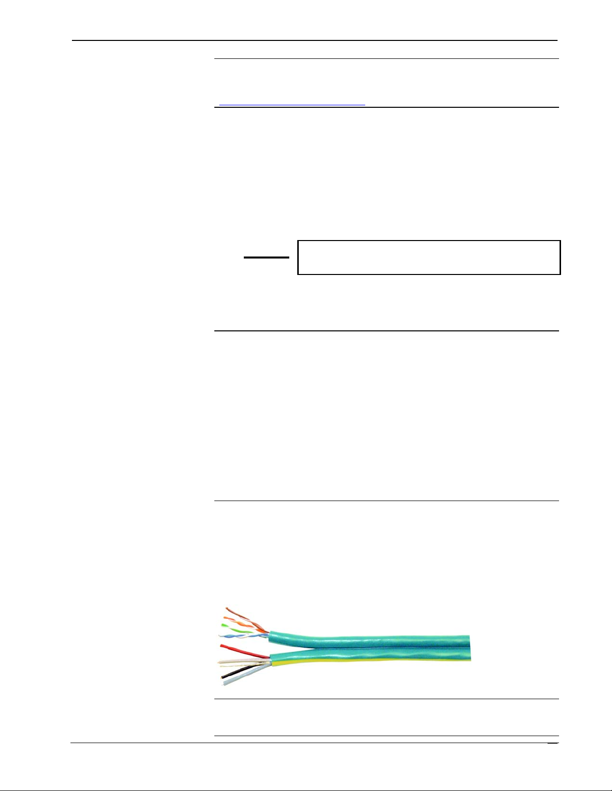
QuickMedia Network Wiring
For the QuickMedia (QM) transport, use CresCAT-QM cable. The Crestron
QuickMedia cable “CresCAT-QM” contains one CAT5E cable and one Cresnet
cable in siamese jackets.
CresCAT-QM Cable
NOTE: Do not untwist the two wires in a single pair for more than 1/3-1/2"
(0.84 – 1.27 cm) when making a connection. The twists are critical to canceling out
interference between the wires.
Operations Guide – DOC. 6375 Tilt Touchpanels: TPS-12/15/17 ¥
15
Page 20
Tilt Touchpanels Crestron Isys® TPS-12/15/17
The aggregate cable length of a signal path originating at a QM transmitter and
terminating at the TPS-12/15/17 must not exceed 328 feet (100 meters). Video
signals may experience a loss of quality over very long lengths of cable. This
phenomenon is due to the added resistance and capacitance of longer cable lengths,
and is not particular to either Crestron and/or QuickMedia systems. To ensure
sufficient bandwidth, the maximum aggregate cable length should not exceed 328
feet. The use of lower-resolution signals may allow increased cable length but must
be tested by the installer with the sources to be used. The QM pin assignment is
based on the EIA/TIA 568B RJ-45 Jack standard.
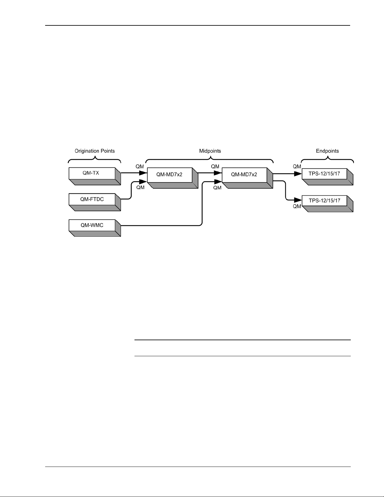
When connecting multiple QM devices, the route between a QM origination point
(transmitter) and a QM endpoint (receiver) cannot have more than two midpoints
(e.g., QM-MD7x2 or other QM switchers). Refer to the following diagram when
configuring a QM network.
QM Network Topology
Identity Code
All equipment and user interfaces within the network require a unique identity code
(Net ID). These codes are two-digit hexadecimal numbers ranging from 03 to FE
(Net ID 02 is reserved for control processors). The Net ID of each unit must match
an ID code specified in the SIMPL Windows program. The Net ID is set using the
internal setup menu (refer to “Interface Menu” on page 18). The Net ID may also be
changed using Crestron Toolbox (refer to “Establishing Communications” on page
43).
Configuring the Touchpanel
NOTE: The only connection required to configure the touchpanel is power (supplied
via Cresnet). Refer to “Hardware Hookup” on page 24 for details.
To configure the unit, it may be necessary to access a series of setup screens prior to
viewing run-time screens that are loaded into the touchpanel for normal operation.
The MAIN MENU for configuring the touchpanel appears when a finger is held to
the touchscreen as power is applied, or after the hardware reset button is pressed and
released. Remove your finger when the message "SETUP MODE" briefly appears on
the touchscreen.
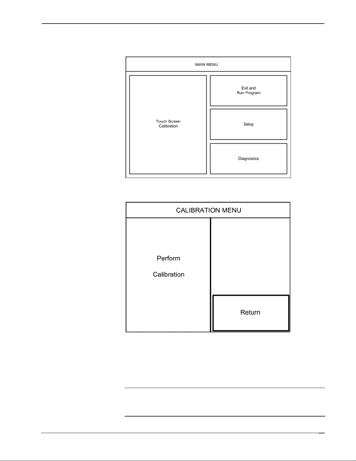
Upon entering SETUP MODE, the MAIN MENU, as shown in the following
illustration, displays four buttons: Touch Screen Calibration, Exit and Run
Program, Setup, and Diagnostics.
The Exit and Run Program button verifies that all of the setup information has
been saved to the EEPROM and displays the main page that has been programmed
¥ Tilt Touchpanels: TPS-12/15/17 Operations Guide – DOC. 6375
16
Page 21
Crestron Isys® TPS-12/15/17 Tilt Touchpanels
into your system. The remaining buttons on the MAIN MENU open other menus,
which are discussed in subsequent paragraphs.
MAIN MENU
Calibration Menu
CALIBRATION MENU
Touch Perform Calibration. The message “Touch Upper Left” appears centered on
the panel with a cross hair in the upper left corner. Touch the center of the cross hair
in the corner of the screen to initiate calibration. Another message, “Touch Upper
Right”, appears with a cross hair in the correct corner. Touch the center of the cross
hair in the corner of the screen. A final message, “Touch Lower Right”, appears with
a cross hair in the correct corner. Touch the center of the cross hair in the corner of
the screen to conclude calibration and return to the CALIBRATION MENU.
NOTE: When touching the screen during calibration, be as accurate as possible.
Use the tip of a capped pen or the eraser end of a pencil. To cancel calibration and
return to the CALIBRATION MENU without saving calibration data, create a
calibration error by touching the screen in the same spot three times.
Operations Guide – DOC. 6375 Tilt Touchpanels: TPS-12/15/17 ¥
17
Page 22

Tilt Touchpanels Crestron Isys® TPS-12/15/17
Setup Menu
To obtain the SETUP MENU, press the Setup button from the MAIN MENU. The
SETUP MENU offers a series of buttons, which open additional menus and displays,
and are detailed in subsequent paragraphs. The SETUP MENU also provides the
screen brightness control, key backlight control, and the standby timeout setting.
After setup parameters have been selected, select the Return button to return to the
MAIN MENU.
NOTE: For convenience, the current CRESNET ID setting is displayed in the upper
left corner.
NOTE: All touchpanel settings are automatically saved in non-volatile memory.
SETUP MENU
Interface Menu
The touchpanel communicates with a control system to activate commands or to
display feedback from components within the system. The communication interface
must be correctly specified or communication will not occur. To set communication
parameters select the Interface button located on the SETUP MENU and display the
INTERFACE MENU, as shown on the next page.
The Cresnet network identity number (CRESNET ID also known as the Net ID) is
displayed on the INTERFACE MENU. Net ID is the two-digit hexadecimal number.
The hexadecimal number can range from 03 to FE and must correspond to the Net
ID set in the SIMPL Windows program of the Cresnet system. Matching IDs
between touchpanel and SIMPL Windows program is required if data is to be
successfully transferred. Net ID for the TPS-12/15/17 is factory set to 03. No two
devices in the same system can have the same Net ID.
¥ Tilt Touchpanels: TPS-12/15/17 Operations Guide – DOC. 6375
18
Page 23

Crestron Isys® TPS-12/15/17 Tilt Touchpanels
INTERFACE MENU
Two buttons adjacent to the hexadecimal display, UP and DOWN, increase and
decrease the Net ID by one, respectively.
The three buttons on the right define how the RS-232 port can be used; as a console
port (i.e., loading touchpanel projects and firmware), a touch output port
(communication of touch coordinates to an external device), and as a mouse input
port (allows a mouse to control the touchpanel).
The touchpanel usually communicates with a Cresnet system. Occasionally the
touchpanel can be used in a demo mode where it merely displays various menus, but
does not communicate with a Cresnet system. In demo mode, the directory buttons
change pages, but buttons requiring feedback do not work. Two side-by-side buttons,
Enable CRESNET II and Disable CRESNET II, determine communication mode.
Select Enable CRESNET II for normal Cresnet communication mode and Disable
CRESNET II to set the touchpanel into demo mode. Communication mode is
factory set to Enable CRESNET II.
There may be Ethernet devices (i.e., a control system) on the network that
communicates with the touchpanel via CIP (Cresnet Internet Protocol). Two buttons
located on the INTERFACE MENU determine if the touchpanel is capable of this
type of communication. Select Enable CIP to permit this protocol recognition and
Disable CIP to prohibit any CIP connection. CIP must be enabled for the touchpanel
to communicate with other Crestron Ethernet devices.
NOTE: The TPS-12/15/17 do not support a wireless Ethernet connection.
Select the Return button located on the INTERFACE MENU to return to the
SETUP MENU.
Operations Guide – DOC. 6375 Tilt Touchpanels: TPS-12/15/17 ¥
19
Page 24

Tilt Touchpanels Crestron Isys® TPS-12/15/17
RS-232 Menu
The touchpanel allows for one of three RS-232 communication modes:
• Console (i.e., loading touchpanel projects and firmware)
• Touch Output (communication of touch coordinates to an external device)
• Mouse Input (allows a mouse to control the touchpanel)
For convenience, the RS-232 MENU also permits the selection of the RS-232
communication options, RTS-CTS On/Off, XON-XOFF On/Off, Baud Rate, Data
Bits, Parity, and Stop Bits.
Touch the communication option to select communication parameters and then select
Save and Return to save the RS-232 settings and return to the SETUP MENU.
Default settings: Console mode, Baud rate: 115200, data bits: 8 bit, parity: none, stop
bit: 1, XON/XOFF on, RTS/CTS off.
RS-232 MENU
¥ Tilt Touchpanels: TPS-12/15/17 Operations Guide – DOC. 6375
20
Page 25

Crestron Isys® TPS-12/15/17 Tilt Touchpanels
Audio Menu
To open the AUDIO MENU, press the Audio button from the SETUP MENU. The
AUDIO MENU offers a series of buttons that adjust the decibel level as indicated by
the gauges. The MIXER INPUTS are independently adjustable, allowing you to
precisely control the amount of signal for each component of the audio mix. The
MASTER OUTPUT provides an overall control of the total volume, bass and treble.
The Restore Default Audio Settings button returns all audio parameters to their
default settings when the button is selected. The Play Test WAV File button plays a
short audio file. The QM Link Status also indicates if the touchpanel is receiving a
QM signal. After audio parameters have been set, select the Return button to return
to the SETUP MENU.
AUDIO MENU
Refer to the following table for additional AUDIO MENU setup details.
Operations Guide – DOC. 6375 Tilt Touchpanels: TPS-12/15/17 ¥
21
Page 26

Tilt Touchpanels Crestron Isys® TPS-12/15/17
Audio Setup Details
AUDIO MENU
DESCRIPTION
CONTROLS
Master The volume of all audio types (WAV, line, and key click) is
Treble Adjusts the overall treble output with the UP▲ and
Bass Adjusts the overall bass output with the UP▲ and
Mute A separate mute button is provided for each of the six mixer
Wave Adjusts the volume of the Wav file with the UP▲ and
Line Adjusts line level audio with the UP▲ and DOWN ▼buttons.
QM (Prog) Adjusts the QM program audio level with the UP▲ and
QM Mic 1 Adjusts the level of microphone 1 with the UP▲ and DOWN
QM Mic 2 Adjusts the level of microphone 2 with the UP▲ and
Key Click Adjusts the level of the key click sound with the UP▲ and
QM Link Status Indicates QM connectivity
affected by the Master Volume control. If the Master Volume
control is set to 100%, the volume for any type of audio is at
maximum. If the Master Volume is set to 0%, the value of all
audio types is overridden and the touchpanel is silent. If Master
Volume is a percentage (say 50%), then all audio types can only
achieve half their value.
DOWN ▼buttons.
DOWN ▼buttons.
inputs and one for the master control.
DOWN ▼buttons. Click Play Test WAV File button to sample
and adjust the volume as a pre-loaded WAV file plays.
DOWN ▼buttons.
▼buttons.
DOWN ▼buttons.
DOWN ▼buttons.
Ethernet
Selection of the Ethernet button from the SETUP MENU displays details such as
the IP Address, Subnet Mask, Default Router, IP Table, etc. The settings can only be
viewed from this screen. The enable/disable Ethernet feature is provided on the
INTERFACE MENU. Ethernet settings are made through Crestron Toolbox. Refer
to page 48 for additional details.
Video Menu
The touchpanel can display composite, S-video, and component video input from
one of the selected sources, from the TPMC-CH-IMC interface unit, a CNX-PVID,
or from the QM input connector in both NTSC and PAL formats. Select the Video
button from the SETUP MENU to display the video screen, shown in the following
illustration. You can select Video Auto Detect, QM Auto Detect, or choose one
particular input source.
Controls for BRIGHTNESS, CONTRAST, SATURATION, and HUE are
provided independently for each video source. Controls for PEAK, BOOST, QM
Preset and auto compensation (AC) are provided for QM video input.
The Restore Default Values button resets the controls to the factory settings. After
video parameters have been set, select the Return button to return to the SETUP
MENU.
Refer to the following graphic and table for additional information.
¥ Tilt Touchpanels: TPS-12/15/17 Operations Guide – DOC. 6375
22
Page 27

Crestron Isys® TPS-12/15/17 Tilt Touchpanels
VIDEO MENU
Video Setup Details
VIDEO SCREEN
CONTROLS
Brightness
Contrast
Saturation
Hue
OM Preset Displays the current QM Preset number.
Peak Peaking adjusts for high frequency attenuation that can occur over
Boost Boost compensates for overall signal loss that can occur over long
AC ON When auto compensation is on, the QM receiving device uses the
AC OFF Turns off auto compensation.
Restore Default
Values
Video Auto Detect Enable the auto-detect mode, automatically selects video source
Composite Selects composite video source at VIDEO IN.
S-Video Selects S-video at VIDEO IN.
Component Selects component video at VIDEO IN.
QM Auto Detect3 Enable the auto-detect mode, automatically selects video source
Composite QM Selects QM composite video source at the QM IN input.
S-Video QM Selects QM S-video source at the QM IN input.
Component QM Selects QM component video source at the QM IN input.
Return Reverts to the SETUP MENU.
1. Video default is 50% for each of the video parameters (brightness, contrast, saturation, and hue).
2. Adjustment applies to the currently selected video source only.
3. QM IN and Video IN are mutually exclusive (i.e., auto-detect for QM IN de-selects auto-detect for
Video IN).
1, 2
Adjust video image brightness with the left and right arrow buttons.
1, 2
Adjust video image contrast with the left and right arrow buttons.
1, 2
Adjust video image saturation with the left and right arrow buttons.
1, 2
Adjust video image hue with the left and right arrow buttons.
long cable lengths.
cable lengths.
auto compensation data received from the QM transmitter.
Returns all settings to the default factory settings.
connected to the VIDEO IN input.
connected to the QM IN input.
DESCRIPTION
Operations Guide – DOC. 6375 Tilt Touchpanels: TPS-12/15/17 ¥
23
Page 28

Tilt Touchpanels Crestron Isys® TPS-12/15/17
Diagnostics Menu
The Diagnostics button from the MAIN MENU contains controls for diagnostic
tools. The diagnostic tools should only be used under supervision from a Crestron
customer service representative during telephone support. The options available from
the DIAGNOSTICS MENU are numeric in nature and their interpretation is beyond
the scope of this manual.
DIAGNOSTICS MENU
Hardware Hookup
Refer to the following diagram and complete the video and communications
connections as needed in any order. Connect the power last.
CAUTION: Do not apply excessive pressure to the touchscreen display during
handling. Doing so can crack the screen and damage the touchpanel.
NOTE: To prevent overheating, do not operate this product in an area that exceeds
the environmental temperature range listed in the table of specifications.
Consideration must be given if installed in a closed or multi-unit rack assembly since
the operating ambient temperature of the rack environment may be greater than the
room ambient. Contact with thermal insulating materials should be avoided on all
sides of the unit. Do not block fan vents.
NOTE: The maximum continuous current from equipment under any external load
conditions shall not exceed a current limit that is suitable for the minimum wire
gauge used in interconnecting cables. The ratings on the connecting unit's supply
input should be considered to prevent overloading the wiring.
NOTE: The headphone output is for WAV and Line audio only. It does not carry the
microphone signal. Use the AUDIO OUT on the TPMC-CH-IMC for the
microphone signal.
NOTE: TPS-12/15/17 touchpanels include a TPMC-CH-IMC Interface Module for
system connection. The TPMC-CH-IMC serves as an interface between the
touchpanel, external A/V system, microphone output, and the Cresnet system. Refer
to the TPMC-CH-IMC Operations Guide (Doc. 6345) for hardware hookup using
this interface.
NOTE: The supplied cable is only for use with the video and Cresnet connections. It
is not designed for the "QM" connection. QM connections should use Crestron
¥ Tilt Touchpanels: TPS-12/15/17 Operations Guide – DOC. 6375
24
Page 29

Crestron Isys® TPS-12/15/17 Tilt Touchpanels
Certified Wire (CresCAT, CresCAT-D, or CresCAT-Q). If the supplied cable is used
for "QM" connections, signal degradation and reduced image quality may result.
NOTE: Crestron recommends an independent power supply for the touchpanel.
Refer to the following diagram for access to the connectors and cable routing.
Access to I/O Panel and Cable Routing
The TPS-12/15/17 touchpanels have rubber pads on the underside of its base so that
it can rest on a horizontal surface. Make the required connections as shown and
described in the following sections. Refer to the following illustration for proper
connections; apply power last.
Operations Guide – DOC. 6375 Tilt Touchpanels: TPS-12/15/17 ¥
25
Page 30

Tilt Touchpanels Crestron Isys® TPS-12/15/17
TPS-12/15/17 Hookup
CAUTION: Only use the TPMC-CH-IMC Interface Module when connecting the
VIDEO IN and AUDIO I/O ports. The use of other “IMC” products could damage
the panel.
NOTE: The QM port is not connected through any “IMC” interface.
NOTE: The connectors are not accessible after the rear cover is reinstalled.
Recommended Cleaning
Keep the surface of the touchscreen free of dirt, dust, or other materials that could
degrade optical properties. Long-term contact with abrasive materials can scratch the
surface, which may detrimentally affect image quality.
For best cleaning results, use a clean, damp, non-abrasive cloth with any
commercially available non-ammonia glass cleaner. Bezels may not provide a
complete watertight seal. Therefore, apply cleaning solution to the cloth rather than
the surface of the touchscreen. Wipe touchscreen clean and avoid getting moisture
beneath the bezels.
¥ Tilt Touchpanels: TPS-12/15/17 Operations Guide – DOC. 6375
26
Page 31

Crestron Isys® TPS-12/15/17 Tilt Touchpanels
Programming Software
Have a question or comment about Crestron software?
Answers to frequently asked questions (FAQs) can be viewed in the Online Help
section of the Crestron website. To post a question or view questions you have
submitted to Crestron’s True Blue Support, log in at http://support.crestron.com.
First-time users will need to establish a user account.
Configuration is easy thanks to Crestron’s Windows®-based programming software.
Crestron SystemBuilder™ software creates a complete project, with no special
programming required. SystemBuilder completes all necessary programming for a
base system including all touchpanel screens and the control system program. The
program output of SystemBuilder is a SIMPL Windows program with much of the
functionality encapsulated in macros and templates. Once SystemBuilder creates the
project, the system interfaces and program logic can be customized in
SystemBuilder. Modifications are easily accomplished with Crestron development
tools (i.e., SIMPL Windows and Crestron VisionTools
packages).
®
Pro-e (VT Pro-e) software
NOTE: Modifications to the program that are made outside of SystemBuilder (for
example, in VT Pro-e or SIMPL windows) are not preserved when you reenter
SystemBuilder.
SystemBuilder comes with templates for all supported interfaces. If a user wishes to
create a touchpanel project using templates with a different look-and-feel, this can be
accomplished by making a custom template. This custom template can then be used
by SystemBuilder to create the final project files to be loaded into the panels.
Alternatively, VT Pro-e can be used to tweak projects created with the
SystemBuilder or develop original touchpanel screen designs.
Digital, analog and serial join numbers are a common thread between VT Pro-e and
SIMPL Windows. These numbers define how the objects on a touchpanel page of a
VT Pro-e project interface to the outside world, specifically the Cresnet system as
defined in the SIMPL Windows program. There are digital join numbers that carry
out some predetermined function (a logical high or low); analog join numbers for
displaying incremental values, sliders, gauges and bar graphs; and serial join
numbers that allow for the display of variable text and transmission/reception of
serial commands from other manufacturers. Unjoined objects are not interfaced with
the system and thus cannot initiate any logic functions (although they can perform
page flips).
Operations Guide – DOC. 6375 Tilt Touchpanels: TPS-12/15/17 ¥
27
Page 32

Tilt Touchpanels Crestron Isys® TPS-12/15/17
Earliest Version Software Requirements for the PC
NOTE: Crestron recommends that you use the latest software to take advantage of
the most recently released features. The latest software is available from the Crestron
website.
The following are recommended software version requirements for the PC:
• (Optional but highly recommended) SystemBuilder version 2.0 or later
(Requires SIMPL Windows, VT Pro-e, Crestron Database and Crestron
Engraver).
• SIMPL Windows version 2.06.16 or later. Requires SIMPL+
Compiler version 1.1 and Device Library update 342.
• Crestron Database version 17.2.0 or later. Required by SIMPL Windows
and VT Pro-e.
• VisionTools Pro-e version 3.4.0.7 or later. Used for graphical touchscreen
design.
• Crestron Toolbox version 1.0 or later. Used for communication, file
transfer, and many other functions (replaces Viewport).
®
Cross
Programming with Crestron System Builder
Crestron System Builder offers automatic programming for such residential and
commercial applications as audio distribution, home theater, video conferencing, and
lighting. The interface of this tool guides you through a few basic steps for
designating rooms and specifying the control system, touchpanels, devices, and
functionality. Crestron System Builder then programs the system, including all
touchpanel projects and control system logic.
Crestron System Builder is fully integrated with the Crestron suite of software
development tools, including SIMPL Windows, VT Pro-e, Crestron Database, User
IR Database, and User Modules Directory. Crestron System Builder accesses these
tools behind the scenes, enabling you to easily create robust systems.
SystemBuilder
For additional details, download SystemBuilder from the Crestron website and
examine the extensive help file.
¥ Tilt Touchpanels: TPS-12/15/17 Operations Guide – DOC. 6375
28
Page 33

Crestron Isys® TPS-12/15/17 Tilt Touchpanels
Programming with SIMPL Windows
NOTE: The following assumes that the reader has knowledge of SIMPL Windows.
If not, refer to the extensive help information provided with the software.
NOTE: The following are acceptable file extensions for programs that include a
TPS-12/15/17, developed for specific control system types:
.smw projectname.smw (source file)
.spz projectname.spz (compiled file for 2-Series)
.usp projectname.usp (source code module for SIMPL+)
.ir projectname.ir (user IR)
.umc projectname.umc (user macro)
.ush projectname.ush (completed SIMPL+)
NOTE: In the following description, the PRO2 control system is used.
SIMPL Windows is Crestron's software for programming Crestron control systems.
It provides a well-designed graphical environment with a number of workspaces
(i.e., windows) in which a programmer can select, configure, program, test, and
monitor a Crestron control system. SIMPL Windows offers drag and drop
functionality in a familiar Windows
This section describes a sample SIMPL Windows program that includes a
TPS-12 touchpanel. Procedures are identical for the TPS-15 and TPS-17.
®
environment.
PRO2 System View
Join Number Remapping (JNR) is a programming concept that allows a TPS Series
panel to use join numbers with values over 4000 (Join Numbers 4001 to 15999 and
Reserved Join Numbers) by bringing them within the range of the TPS touchpanel
symbol, thereby increasing a touchpanel’s functionality. Through JNR, a TPS Series
panel’s internal functions become accessible to a control system and can activate the
local functions of other touchpanels, route its internal feedback back to the control
system, and receive feedback from remote locations. JNR provides the additional
capability of managing IP IDs in Ethernet applications where a touchpanel
communicates with multiple control systems that have been uploaded with the same
program. Refer to the latest version of the 2-Series Control System Reference Guide
(Doc. 6256) and the SIMPL Windows help file for more details.
Configuration Manager is where programmers “build” a Crestron control system by
selecting hardware from the Device Library. In Configuration Manager, drag the
PRO2 from the Control Systems folder of the Device Library and drop it in the upper
pane of the System Views. The PRO2 with its associated communication ports is
displayed in the System Views upper pane.
The System Views lower pane displays the PRO2 system tree. This tree can be
expanded to display and configure the communications ports.
Operations Guide – DOC. 6375 Tilt Touchpanels: TPS-12/15/17 ¥
29
Page 34

Tilt Touchpanels Crestron Isys® TPS-12/15/17
Expanded PRO2 System Tree
C2Net-Device Slot in Configuration Manager
To incorporate the TPS-12/15/17 touchpanel into the system, drag the touchpanel
from the Touchpanels folder (Cresnet or Ethernet) of the Device Library and drop it
on the C2Net-Device Slot. The PRO2 system tree displays the touchpanel in Slot 9,
with a default Net ID of 03, as shown in the following illustration. Additional
touchpanels will be added with the next available Net ID number.
C2Net Device, Slot 9
Setting the Net ID in Device Settings
Double-click the TPS-12 icon in the upper pane to open the “Device Settings”
window. This window displays TPS-12 device information. If necessary, select the
Net ID tab to change the Net ID, as shown in the following figure.
“Device Settings” Window for the TPS-12
¥ Tilt Touchpanels: TPS-12/15/17 Operations Guide – DOC. 6375
30
Page 35

Crestron Isys® TPS-12/15/17 Tilt Touchpanels
NOTE: This procedure sets the Net ID for the touchpanel in the program only. It
does not automatically set the Net ID for the touchpanel itself. SIMPL Windows
automatically changes Net ID values of a device added to a program if a duplicate
device or a device with the same Net ID already exists in the program. Always
ensure that the hardware and software settings of the Net ID match. For Net ID
hardware settings details, refer to “Interface Menu” which begins on page 18.
TPS-12/15/17 Symbol in Programming Manager
Programming Manager is where programmers "program" a Crestron control system
by assigning signals to symbols. The symbol can be viewed by double clicking on
the icon or dragging it into Detail View. A description for each signal in the symbol
is described in the SIMPL Windows help file (F1).
Device Extenders
Device extenders provide additional logic and functionality to a device. Three device
extenders are currently available for the TPS-12/15/17 touchpanels.
• The Poll Manager takes the touchpanel on and off line during polling by the
control system
• The Sleep/Wake Manager suspends and restores operation of the touchpanel
• Activity Detection symbol indicates that the control system has received
analog, digital or serial data (below join 17000) from the device
For additional information about Device Extenders, refer to the latest version of the
Crestron SIMPL Windows Symbol Guide (Doc. 6120), or the on-line help included
with SIMPL Windows.
Example Program
An example program for the TPS-12/15/17 is available from the “Example Program”
section of the Crestron website (http://www.crestron.com/exampleprograms). Search
for TPS-12/15/17.zip.
Programming with VisionTools Pro-e
VT Pro-e, a design and programming Windows-based software, permits the
creation of unlimited control screen variations incorporating two and threedimensional graphics and text as well as video and sounds (recorded as WAV files).
A set of pages, which make up a project, can be designed for each touchpanel
application. Each page contains objects such as custom control graphics, two and
three-dimensional buttons, sliders, and digital readouts which allow the user to
interface with the control system via join numbers. Unjoined objects are not
interfaced with the system and thus cannot initiate any functions. The completed and
compiled project is uploaded to the touchpanel and programmed into the flash
PROM via the File | Upload Project command. The touchpanel uses the
programmed project until another set is uploaded from the PC. The PC may be
disconnected from the control system or panel except during reprogramming. VT
Pro-e also allows users the option to generate projects destined for web browsers
rather than for physical touchpanels.
For additional software information, refer to the help file provided with the software.
The latest version of VT Pro-e can be obtained from the Crestron website.
Operations Guide – DOC. 6375 Tilt Touchpanels: TPS-12/15/17 ¥
31
Page 36

Tilt Touchpanels Crestron Isys® TPS-12/15/17
p
Multi-Mode Objects
Multi-mode objects offer high-
erformance programming!
The single most-advanced VT Pro-e high-performance programming technique
involving the TPS-12/15/17 is the concept of multi-mode objects. A multi-mode
object (i.e., button, legend, etc.) is an object drawn on a VT Pro-e page that can have
one or more active and inactive visible settings (modes).
For examples, refer to http://www.crestron.com/downloads/example_programs.asp
and search for Multi-mode object examples. This file contains the VT Pro-e
touchpanel files and SIMPL Windows files that illustrate the high-performance
capabilities of multi-mode objects.
WAV File Audio Messages
The TPS-12/15/17 touchpanels are capable of playing audio messages as system
prompts and responses. These files are recorded as WAV files on a PC using an
audio utility such as Sound Recorder that is packaged with Microsoft Windows
95/98/Me/XP/NT/ 2000™. Files from other sources may also be converted to an
acceptable format by using this or a similar utility. Many other audio utilities are
available commercially or as shareware. The TPS-12/15/17 touchpanels only accept
the following WAV file format: PCM, 8KHz, mono, 8-bit. For more information
about how to use Sound Recorder, refer to its User’s Guide and extensive help
information provided with the software. Also refer to the help file in VT Pro-e to
learn how to use its audio tool, Sound Manager, to attach WAV files to a touchpanel
project.
Pre-recorded WAV files for voice prompts and responses are available from
Crestron. These files can be stored into and programmed for use in the touchpanel
directly or may be edited with the Sound Recorder. For example, the individual files
can be combined to create custom messages.
NOTE: Touchpanel WAV files can be obtained from the Wave LC Library of the
Crestron FTP site.
Bit Depth and File Size
A bit depth refers to the number of memory bits used to store color data for each
pixel in a raster image. A touchpanel raster image consists of a rectangular grid of
picture elements (pixels). Each pixel uses the same amount of memory to store its
color data. The amount of memory is called the bit depth of the image.
Greater bit depths are required to represent finer gradations of color. Increasing bit
depth necessarily increases file size. A black and white drawing requires only one bit
per pixel to store all the available color information. Using a 32-bit per pixel bit
depth for a black and white image increases the file size 32 times, without adding
anything to the black and white image quality.
In an 8-bit per pixel system, the associated 8-bits of video memory for every screen
pixel, contains a value referring to a location in an 8-bit color table. In this way, any
one of the specific 256 color table locations is assigned to a pixel.
A 16-bit highcolor system is considered sufficient to provide life-like colors. It is
encoded using 5-bits to represent red, 5-bits to represent blue, but (since the human
eye is more sensitive to the color green) 6-bits to represent 64 levels of green. These
can therefore be combined to provide 65,536 mixed colors (32 x 32 x 64 = 65,536).
In a 24-bit graphics display, the video memory allocates 24 bits for each pixel on the
screen, enabling each pixel to take on any one of a possible 16.7 million colors. Each
24-bit value is composed of 8-bits for red, 8-bits for green, and 8-bits for blue. These
triplets of 8-bit values are also referred to as the red, green, and blue color planes. A
24-bit image is actually composed of three component images, which combine to
¥ Tilt Touchpanels: TPS-12/15/17 Operations Guide – DOC. 6375
32
Page 37

Crestron Isys® TPS-12/15/17 Tilt Touchpanels
create the truecolor picture. The reason this is called truecolor is that this is around
the maximum number of colors the human eye is able to detect.
Truecolor images are sometimes represented by a 32-bit value. The extra 8-bits do
not enhance the precision of the color representation, but act as an alpha channel that
represents pixel translucency. The 32-bit truecolor has become popular on the
computer desktop to provide effects such as translucent windows, fading menus, and
shadows.
In graphics intensive applications such as touchpanels, raising or lowering the color
depth of the displayed graphics can achieve a balance of performance and quality.
Lower color depths do not require as much frame buffer memory or display
bandwidth, allowing them to be generated and displayed more quickly. Increasing
color depth results in higher color quality at the expense of display speed and
responsiveness. By using a majority of 8-bit or 16-bit graphics, and holding the
32-bit graphics to a minimum (ex. for a family photo, etc.), you can create a
sophisticated project that will fit in the memory space provided, and have the
touchpanel remain very responsive.
Relationship of Bits to Colors
NUMBER OF BITS NUMBER OF COLORS
1 bit Black and White
2 bits 4 Colors
4 bits 16 Colors
8 bits 256 Colors
16 bits 65,536 Colors (Highcolor)
24 bits 16.7 million Colors (Truecolor)
32 bits 16.7 million Colors plus Transparency
When creating a VT Pro-e project, you can elect to compress and reduce the image
size in the “Page Properties” window for the entire page, and/or perform the same
function of reducing the image size using the “Image Properties” window. A
reduction in image size will save a considerable amount of memory space for your
project.
In VT Pro-e, the Compress checkbox permits the image to be compressed when
compiling. The 16 Bits checkbox converts a 24-bit or 32-bit image to 16 bits. This
conversion to a 16-bit image may cause the loss of some subtle shading. To
compensate for this, use the dithering to simulate the original shading. Various
dithering types are available. Refer to the following illustrations.
Operations Guide – DOC. 6375 Tilt Touchpanels: TPS-12/15/17 ¥
33
Page 38

Tilt Touchpanels Crestron Isys® TPS-12/15/17
VT Pro-e “Page Properties” Window – Bit Depth Selection VT Pro-e “Image Properties” Window – Bit Depth Selection
Hard Button Programming
Four of the buttons can be programmed to access any frequently used command.
Each button has a permanently fixed digital join number. The sequence of digital
join numbers is (left to right) 1 through 4. Refer to the following diagram for their
assigned join numbers. A description for each button signal is described in the
SIMPL Windows help file (F1).
Pushbutton Layout and Join Number Assignment
Join1Join
Join
Join
3
2
4
Reserved Join Numbers
A reserved join number is a feature of the software that enables a designer to create a
button that completes a predetermined function. The tables that follow provide a list
of reserved join numbers available within the software.
NOTE: Many touchpanel configuration “shortcuts” are available via the software. A
button can be created on a page that either calls up the Preferences Menu, adjusts
brightness, etc., via reserved join numbers.
¥ Tilt Touchpanels: TPS-12/15/17 Operations Guide – DOC. 6375
34
Page 39

Crestron Isys® TPS-12/15/17 Tilt Touchpanels
Video Properties Reserved Joins
NUMBER FUNCTION INPUT OUTPUT TYPE
17101 Comp Tp YES YES DIGITAL
17102 Svideo Tp YES YES DIGITAL
17103 Auto Det Tp YES YES DIGITAL
17119 No Input Flag NO YES DIGITAL
17122 Defaults YES NO DIGITAL
System Reserved Joins
NUMBER FUNCTION INPUT OUTPUT TYPE
17153 Auto Det Tp YES YES DIGITAL
17201 Factory Defaults YES NO DIGITAL
17202 Show Config YES NO DIGITAL
17203 Selftest YES NO DIGITAL
17204 Input Ts YES YES DIGITAL
17205 Input Mouse YES YES DIGITAL
17208 Mode Console YES YES DIGITAL
17210 Cresnet Enable YES YES DIGITAL
17211 Cresnet Disable YES YES DIGITAL
17212 Cip On YES YES DIGITAL
17213 Cip Off YES YES DIGITAL
17214 Cresnet ID Down YES YES DIGITAL
17215 Cresnet ID Up YES YES DIGITAL
17216 Lcd Brt Up YES NO DIGITAL
17217 Lcd Brt Dn YES NO DIGITAL
17218 Lcd Brt High YES NO DIGITAL
17219 Lcd Brt Med YES NO DIGITAL
17220 Lcd Brt Lo YES NO DIGITAL
17222 Perform Calibration YES NO DIGITAL
17223 Touch Values YES NO DIGITAL
17229 Backlight On YES YES DIGITAL
17230 Backlight Off YES YES DIGITAL
17231 Standby Timeout Up YES NO DIGITAL
17232 Standby Timeout Down YES NO DIGITAL
17235 Exit and Run Program NO NO DIGITAL
17236 Save NO NO DIGITAL
17239 Test Pattern YES NO DIGITAL
17240 Display Eeprom YES NO DIGITAL
17261 Not Tpi Flag NO YES DIGITAL
17262 Display Ethernet YES NO DIGITAL
17263 Mode Touchout YES NO DIGITAL
17265 Touchout Action 0 YES YES DIGITAL
17266 Touchout Action 1 YES YES DIGITAL
17267 Touchout Action 2 YES YES DIGITAL
Continued on the following page
Operations Guide – DOC. 6375 Tilt Touchpanels: TPS-12/15/17 ¥
35
Page 40

Tilt Touchpanels Crestron Isys® TPS-12/15/17
System Reserved Joins (continued)
NUMBER FUNCTION INPUT OUTPUT TYPE
17268 Touchout Action 3 YES YES DIGITAL
17269 Touchout Action 4 YES YES DIGITAL
17270 Touchout Action 5 YES YES DIGITAL
17271 Touchout Action 6 YES YES DIGITAL
17272 Touchout Action 7 YES YES DIGITAL
17273 Touchout Action 8 YES YES DIGITAL
17274 Touchout Action 9 YES YES DIGITAL
17275 Touchout Action A YES YES DIGITAL
17276 Touchout Action B YES YES DIGITAL
17277 Touchout Action C YES YES DIGITAL
17278 Touchout Action D YES YES DIGITAL
17279 Touchout Action E YES YES DIGITAL
17280 Touchout Action F YES YES DIGITAL
17281 Touchout State Up YES NO DIGITAL
17282 Touchout State Dn YES NO DIGITAL
17283 Input Ts Off YES YES DIGITAL
17285 Selftest Running NO YES DIGITAL
17286 Setup Blank Page Press NO YES DIGITAL
17287 Setup Active NO YES DIGITAL
17200 Cresnet ID YES YES ANALOG
17201 Lcd Brt YES YES ANALOG
17203 Standby Timeout YES YES ANALOG
17204 Touchout State A YES YES ANALOG
17205 Touchout Destination A YES YES ANALOG
17206 Touchout Channel A YES YES ANALOG
17207 Touchout Analog Join A YES YES ANALOG
17208 Touchout Analog Join Plus One A YES YES ANALOG
17209 Touchout Format A YES YES ANALOG
17210 Touchout State B YES YES ANALOG
17211 Touchout Destination B YES YES ANALOG
17212 Touchout Channel B YES YES ANALOG
17213 Touchout Analog Join B YES YES ANALOG
17214 Touchout Analog Join Plus One B YES YES ANALOG
17215 Touchout Format B YES YES ANALOG
32768 Product Name Text Join NO YES SERIAL
32769 Product Version Text Join NO YES SERIAL
32770 Everything Else Text Join NO YES SERIAL
¥ Tilt Touchpanels: TPS-12/15/17 Operations Guide – DOC. 6375
36
Page 41

Crestron Isys® TPS-12/15/17 Tilt Touchpanels
Audio Reserved Joins
NUMBER FUNCTION INPUT OUTPUT TYPE
17300 All Audio On YES YES DIGITAL
17301 All Audio Off YES YES DIGITAL
17302 Key Click On YES YES DIGITAL
17303 Key Click Off YES YES DIGITAL
17304 Key Click Volume Up YES NO DIGITAL
17305 Key Click Volume Down YES NO DIGITAL
17306 Line On YES YES DIGITAL
17307 Line Off YES YES DIGITAL
17308 Line Volume Up YES NO DIGITAL
17309 Line Volume Down YES NO DIGITAL
17312 WAV On YES YES DIGITAL
17313 WAV Off YES YES DIGITAL
17314 WAV Volume Up YES NO DIGITAL
17315 WAV Volume Down YES NO DIGITAL
17320 Play Test WAV File YES NO DIGITAL
17321 Defaults YES NO DIGITAL
17322 Beep Short YES NO DIGITAL
17323 Beep Medium YES NO DIGITAL
17324 Beep Long YES NO DIGITAL
17325 Bass Up YES NO DIGITAL
17326 Bass Dn YES NO DIGITAL
17327 Treble Up YES NO DIGITAL
17328 Treble Dn YES NO DIGITAL
17329 All Audio Volume Up YES NO DIGITAL
17330 All Audio Volume Down YES NO DIGITAL
17349 Master Mute Button YES NO DIGITAL
17350 Keyclick Mute Button YES NO DIGITAL
17351 Line Mute Button YES NO DIGITAL
17352 Wave Mute Button YES NO DIGITAL
17300 Key Click Volume YES YES ANALOG
17301 Line Volume YES YES ANALOG
17302 WAV Volume YES YES ANALOG
17305 Bass YES YES ANALOG
17306 Treble YES YES ANALOG
17307 All Audio Volume YES YES ANALOG
Ethernet Reserved Joins
NUMBER FUNCTION INPUT OUTPUT TYPE
17401 Board On YES YES DIGITAL
17402 Board Off YES YES DIGITAL
Operations Guide – DOC. 6375 Tilt Touchpanels: TPS-12/15/17 ¥
37
Page 42

Tilt Touchpanels Crestron Isys® TPS-12/15/17
RS-232 Control Reserved Joins
NUMBER FUNCTION INPUT OUTPUT TYPE
17600 Baud 115200 YES YES DIGITAL
17601 Baud 57600 YES YES DIGITAL
17602 Baud 38400 YES YES DIGITAL
17603 Baud 19200 YES YES DIGITAL
17604 Baud 9600 YES YES DIGITAL
17605 Baud 4800 YES YES DIGITAL
17606 Baud 2400 YES YES DIGITAL
17607 Baud 1200 YES YES DIGITAL
17608 Baud 600 YES YES DIGITAL
17609 Baud 300 YES YES DIGITAL
17610 Baud 150 YES YES DIGITAL
17611 Baud 110 YES YES DIGITAL
17612 Data 8 YES YES DIGITAL
17613 Data 7 YES YES DIGITAL
17614 Par None YES YES DIGITAL
17615 Par Odd YES YES DIGITAL
17616 Par Even YES YES DIGITAL
17617 Stop 1 YES YES DIGITAL
17618 Stop 2 YES YES DIGITAL
17619 Rts Cts On YES YES DIGITAL
17620 Rts Cts Off YES YES DIGITAL
17621 Xon Xoff On YES YES DIGITAL
17622 Xon Xoff Off YES YES DIGITAL
17623 Load Params YES NO DIGITAL
Screen Information Reserved Joins
NUMBER FUNCTION INPUT OUTPUT TYPE
17700 Size 800x600 NO YES DIGITAL
17701 Size 1024x768 NO YES DIGITAL
17705 Size 1280x768 NO YES DIGITAL
¥ Tilt Touchpanels: TPS-12/15/17 Operations Guide – DOC. 6375
38
Page 43

Crestron Isys® TPS-12/15/17 Tilt Touchpanels
System 2 Reserved Joins
NUMBER FUNCTION INPUT OUTPUT TYPE
19219 Src Ctrl All Gain Up YES NO DIGITAL
19220 Src Ctrl All Gain Dn YES NO DIGITAL
19221 Src Ctrl Contrast Up YES NO DIGITAL
19222 Src Ctrl Contrast Dn YES NO DIGITAL
19237 Src Ctrl Saturation Up YES NO DIGITAL
19238 Src Ctrl Saturation Down YES NO DIGITAL
19239 Src Ctrl Hue Up YES NO DIGITAL
19240 Src Ctrl Hue Down YES NO DIGITAL
19119 Src Ctrl All Gain NO NO ANALOG
19121 Src Ctrl Contrast NO NO ANALOG
19123 Src Ctrl Saturation NO NO ANALOG
19125 Src Ctrl Hue NO NO ANALOG
SVID-1 Control Reserved Joins
NUMBER FUNCTION INPUT OUTPUT TYPE
19619 SVID-1 Brightness Up YES YES DIGITAL
19620 SVID-1 Brightness Down YES YES DIGITAL
19621 SVID-1 Contrast Up YES YES DIGITAL
19622 SVID-1 Contrast Down YES YES DIGITAL
19637 SVID-1 Saturation Up YES YES DIGITAL
19638 SVID-1 Saturation Down YES YES DIGITAL
19639 SVID-1 Hue Up YES YES DIGITAL
19640 SVID-1 Hue Down YES YES DIGITAL
19519 SVID-1 Brightness YES YES ANALOG
19521 SVID-1 Contrast YES YES ANALOG
19523 SVID-1 Saturation YES YES ANALOG
19525 SVID-1 Hue YES YES ANALOG
SVID-2 Control Reserved Joins
NUMBER FUNCTION INPUT OUTPUT TYPE
19719 SVID-2 Brightness Up YES YES DIGITAL
19720 SVID-2 Brightness Down YES YES DIGITAL
19721 SVID-2 Contrast Up YES YES DIGITAL
19722 SVID-2 Contrast Down YES YES DIGITAL
19737 SVID-2 Saturation Up YES YES DIGITAL
19738 SVID-2 Saturation Down YES YES DIGITAL
19739 SVID-2 Hue Up YES YES DIGITAL
19740 SVID-2 Hue Down YES YES DIGITAL
19619 SVID-2 Brightness YES YES ANALOG
19621 SVID-2 Contrast YES YES ANALOG
19623 SVID-2 Saturation YES YES ANALOG
19625 SVID-2 Hue YES YES ANALOG
Operations Guide – DOC. 6375 Tilt Touchpanels: TPS-12/15/17 ¥
39
Page 44

Tilt Touchpanels Crestron Isys® TPS-12/15/17
Composite-1A Control Reserved Joins
NUMBER FUNCTION INPUT OUTPUT TYPE
19819 Composite-1A Brightness Up YES YES DIGITAL
19820 Composite-1A Brightness
Down
19821 Composite-1A Contrast Up YES YES DIGITAL
19822 Composite-1A Contrast Down YES YES DIGITAL
19837 Composite-1A Saturation Up YES YES DIGITAL
19838 Composite-1A Saturation Down YES YES DIGITAL
19839 Composite-1A Hue Up YES YES DIGITAL
19840 Composite-1A Hue Down YES YES DIGITAL
19719 Composite-1A Brightness YES YES ANALOG
19721 Composite-1A Contrast YES YES ANALOG
19723 Composite-1A Saturation YES YES ANALOG
19725 Composite-1A Hue YES YES ANALOG
Composite-2A Control Reserved Joins
NUMBER FUNCTION INPUT OUTPUT TYPE
20119 Composite-2A Brightness Up YES YES DIGITAL
20120 Composite-2A Brightness
Down
20121 Composite-2A Contrast Up YES YES DIGITAL
20122 Composite-2A Contrast Down YES YES DIGITAL
20137 Composite-2A Saturation Up YES YES DIGITAL
20138 Composite-2A Saturation Down YES YES DIGITAL
20139 Composite-2A Hue Up YES YES DIGITAL
20140 Composite-2A Hue Down YES YES DIGITAL
20019 Composite-2A Brightness YES YES ANALOG
20021 Composite-2A Contrast YES YES ANALOG
20023 Composite-2A Saturation YES YES ANALOG
20025 Composite-2A Hue YES YES ANALOG
YES YES DIGITAL
YES YES DIGITAL
¥ Tilt Touchpanels: TPS-12/15/17 Operations Guide – DOC. 6375
40
Page 45

Crestron Isys® TPS-12/15/17 Tilt Touchpanels
YPbPr-1 Control Reserved Joins
NUMBER FUNCTION INPUT OUTPUT TYPE
20419 YPbPr-1 Brightness Up YES YES DIGITAL
20420 YPbPr-1 Brightness Down YES YES DIGITAL
20421 YPbPr-1 Contrast Up YES YES DIGITAL
20422 YPbPr-1 Contrast Down YES YES DIGITAL
20437 YPbPr-1 Saturation Up YES YES DIGITAL
20438 YPbPr-1 Saturation Down YES YES DIGITAL
20439 YPbPr-1 Hue Up YES YES DIGITAL
20440 YPbPr-1 Hue Down YES YES DIGITAL
20319 YPbPr-1 Brightness YES YES ANALOG
20321 YPbPr-1 Contrast YES YES ANALOG
20323 YPbPr-1 Saturation YES YES ANALOG
20325 YPbPr-1 Hue YES YES ANALOG
20519 YPbPr-2 Brightness Up YES YES DIGITAL
20520 YPbPr-2 Brightness Down YES YES DIGITAL
20521 YPbPr-2 Contrast Up YES YES DIGITAL
20522 YPbPr-2 Contrast Down YES YES DIGITAL
20537 YPbPr-2 Saturation Up YES YES DIGITAL
20538 YPbPr-2 Saturation Down YES YES DIGITAL
20539 YPbPr-2 Hue Up YES YES DIGITAL
20540 YPbPr-2 Hue Down YES YES DIGITAL
QM Audio Reserved Joins
NUMBER FUNCTION INPUT OUTPUT TYPE
22202 Audio Src-1 Program On YES YES DIGITAL
22203 Audio Src-1 Program Off YES YES DIGITAL
22204 Audio Src-1 Program Volume
Up
22205 Audio Src-1 Program volume
Down
22208 Audio Src-1 Mic-1 On YES YES DIGITAL
22209 Audio Src-1 Mic-1 Off YES YES DIGITAL
22210 Audio Src-1 Mic-1 Volume Up YES NO DIGITAL
22211 Audio Src-1 Mic-1 Volume
Down
22212 Audio Src-1 Mic-2 On YES YES DIGITAL
22213 Audio Src-1 Mic-2 Off YES YES DIGITAL
22214 Audio Src-1 Mic-2 Volume Up YES NO DIGITAL
22215 Audio Src-1 Mic-2 Volume
Down
22246 Audio Src-1 Linked YES NO DIGITAL
22248 Audio Src-1 Program Mute
Button
22249 Audio Src-1 Mic-1 Mute Button YES NO DIGITAL
22250 Audio Src-1 Mic-2 Mute Button YES NO DIGITAL
Continued on the following page
YES NO DIGITAL
YES NO DIGITAL
YES NO DIGITAL
YES NO DIGITAL
YES NO DIGITAL
Operations Guide – DOC. 6375 Tilt Touchpanels: TPS-12/15/17 ¥
41
Page 46

Tilt Touchpanels Crestron Isys® TPS-12/15/17
QM Audio Reserved Joins (continued)
NUMBER FUNCTION INPUT OUTPUT TYPE
22251 Audio Src-2 Program Mute
22252 Audio Src-2 Mic-1 Mute Button YES NO DIGITAL
22253 Audio Src-2 Mic-2 Mute Button YES NO DIGITAL
22200 Audio Src-1 Program Volume YES YES ANALOG
22203
22208 Audio Src-1 Mic-2 Volume YES YES ANALOG
Audio Src-1 Mic-1 Volume YES YES ANALOG
Button
Video Compensation Reserved Joins
NUMBER FUNCTION INPUT OUTPUT TYPE
22300 Video Input-1 Peak Up YES YES DIGITAL
22301 Video Input-1 Peak Down YES YES DIGITAL
22302 Video Input-1 Boost Up YES YES DIGITAL
22303 Video Input-1 Boost Down YES YES DIGITAL
22310 Video Input-1 Auto
22311 Video Input-1 Auto
22320 Video Compensation Preset Up YES YES DIGITAL
22321 Video Compensation Preset
22322 Video Compensation Preset
22323 Video Compensation Preset
22300 Video Input-1 Peak YES YES ANALOG
22301 Video Input-1 Boost YES YES ANALOG
22305 QM Link 1 Preset/# YES YES ANALOG
Compensation On
Compensation Off
Down
Load
Store
YES NO DIGITAL
YES YES DIGITAL
YES YES DIGITAL
YES YES DIGITAL
YES YES DIGITAL
YES YES DIGITAL
MultiByte International Characters
Most languages use a single byte of 8 bits to represent a character, e.g. English,
French, German, Hebrew, Russian, Thai, etc.
Multibyte character fonts require more than the usual 8 bits to specify a character.
This occurs when a language has more than 256 characters (2
example, Chinese fonts contain several thousand characters. Other multibyte
languages include Japanese and Korean.
There are two separate issues with multibyte characters – static text on buttons and
indirect text on buttons. No Isys touchpanel firmware changes are required in either
case.
Static text on a button, entered in the standard way in VT Pro-e, always works under
Windows 98. Under Windows XP, you must use VT Pro-e 3.0 or later.
Indirect text on a button is entered in VT Pro-e and the actual string to be displayed
is entered in SIMPL Windows. You must use VT Pro-e 3.0 or later to guarantee that
the full set of characters in the font is stored on the touchpanel. You must use SIMPL
Windows 2.03.11 or later to enter Chinese characters directly. As of this publication
date, only completely single byte or completely multibyte strings may be entered or
they will not be compiled correctly in SIMPL Windows. In other words, you cannot
enter Chinese character interspersed with numbers. You can enter Chinese characters
¥ Tilt Touchpanels: TPS-12/15/17 Operations Guide – DOC. 6375
42
8
) in a font. For
Page 47

Crestron Isys® TPS-12/15/17 Tilt Touchpanels
or numbers in separate strings. Crestron is scheduling time to fix this in the near
future and the release notes for SIMPL Windows will mention it.
Of course, you can always use the workaround of showing a graphic that displays the
string, but it is not dynamic. To compile and use multibyte characters, it is essential
that the operating system understand the language. Windows XP is available in many
international languages, and add-on software is available for other versions of
Windows.
Uploading and Upgrading
NOTE: Crestron recommends using the latest programming software and that each
device contains the latest firmware to take advantage of the most recently released
features. Please check the Crestron website (http://www.crestron.com/updates
the latest versions of software and firmware. New users are required to register to
obtain access to this site.
Assuming a PC is properly connected to the entire system, Crestron programming
software allows the programmer to upload programs, projects and firmware to the
system and touchpanels after their development. However, there are times when the
files for the program and projects are compiled and not uploaded. Instead, compiled
files may be distributed from programmers to installers, from Crestron to dealers,
etc. Even firmware upgrades are available from the Crestron website as new features
are developed after product releases. In those instances, one has the option to upload
via the programming software or to upload and upgrade via the Crestron Toolbox.
) for
NOTE: The Crestron Toolbox (replacement for Crestron Viewport, you may
continue to use Viewport if desired) is a broad-based software package that
accomplishes multiple system tasks, primarily using an RS-232 or TCP/IP
connection between a PC and one or more Crestron control systems.
The following sections define how to upload a SIMPL Windows program, VT Pro-e
project, or upgrade touchpanel firmware. However, before attempting to upload or
upgrade, it is necessary to establish communications between the PC and the
touchpanel.
Establishing Communications
When communicating with a touchpanel from a PC, one of three communication
methods can be used.
• Indirect RS-232 serial communication via control system
• Direct RS-232 serial communication
• TCP/IP communication
Indirect Serial Communication via Control System
The procedure in this section provides details for RS-232 communication between
the PC and the touchpanel via the control system. This method can be used to
communicate with the control system directly and with a touchpanel via the control
system’s Cresnet connection.
Refer to the following figure for a typical connection diagram connecting to a
touchpanel via a control system.
Operations Guide – DOC. 6375 Tilt Touchpanels: TPS-12/15/17 ¥
43
Page 48

Tilt Touchpanels Crestron Isys® TPS-12/15/17
Indirect Serial Communications Setup Connections
1. Ensure that all devices are connected to the control processor and the
control processor is connected via serial cable to the PC.
2. Open Crestron Toolbox and click Tools | Manage Address Book to display
a list of available devices. Select Serial on COM1 as the connection type.
Serial on COM1 is an entry in the DefaultAddressBook that is included
with Crestron Toolbox.
The PC communication settings specified here should match the protocol
that the control processor expects. The usual settings are as follows:
• Port = COM 1 through COM 8. Select the correct COM port on the
PC.
• Baud rate = Auto-Detect.
• Parity = None.
• Number of data bits = 8.
• Number of stop bits = 1.
• Hardware handshaking (RTS/CTS) enabled.
• Software handshaking (XON/XOFF) not enabled.
“Address Book” Window – Serial Setup
¥ Tilt Touchpanels: TPS-12/15/17 Operations Guide – DOC. 6375
44
Page 49

Crestron Isys® TPS-12/15/17 Tilt Touchpanels
3. After setting the correct parameters, click OK to return to the Crestron
Toolbox main window.
4. Click Tools | Network Device Tree, or click the network device tree icon
to display the devices in the system. Communications are confirmed
when the network devices are displayed.
Network Device Tree
To view a specific device, expand the network device tree by clicking +.
Expand the network device tree till the device to be managed is selected.
Right-click the desired Net ID to open the sub-menu. This menu provides a
wide range of functions, including; change the Net ID, open text console,
upload project, update firmware, etc.
Network Device Tree Sub-Menu -Functions
NOTE: Toolbox displays a customized list of functions depending on the type of
device with which it is communicating.
Operations Guide – DOC. 6375 Tilt Touchpanels: TPS-12/15/17 ¥
45
Page 50

Tilt Touchpanels Crestron Isys® TPS-12/15/17
Direct Serial Communication
Crestron devices that have an RS-232 port can be connected directly to a PC.
To prepare the touchpanel for direct communication from a PC, refer to the
following figure. Connect the RS-232 port of the computer directly to the RS-232
port of the touchpanel using Crestron Cable Number STCP-502PC. Refer to page 10
for pin assignments.
NOTE: Direct serial communication is a faster method for transferring programming
and projects than indirect serial communication, which uses the control system’s
Cresnet connection.
Direct Serial Communications Setup Connections
1. Apply power to the touchpanel.
2. Open Crestron Toolbox.
3. Click the Address Book icon , or select Tools | Manage Address
Book to open the Address Book. The Address Book allows you to maintain
a list of accessible control systems and network devices. You can establish a
session with any or all of the devices in the address book (provided the PC
has a valid connection to each Cresnet or Ethernet network).
4. Select the device from the Address Book or click Add Entry and type a
name for the new device, such as Touchpanel Direct.
5. Select RS232 as the Connection Type and select the serial settings of the
device. This sets the PC to the same serial settings. Enter the settings and
click OK.
For touchpanels, the default settings are:
• Port = COM 1
• Baud Rate = 152000 (or select Auto-Detect)
• Parity = None
• Data Bits = 8
• Stop Bits = 1
• Hardware Handshaking (RTS/CTS) = On
• Software Handshaking (XON/XOFF) = Off
¥ Tilt Touchpanels: TPS-12/15/17 Operations Guide – DOC. 6375
46
Page 51

Crestron Isys® TPS-12/15/17 Tilt Touchpanels
Crestron Toolbox Address Book Setup
6. Select Tools | System Info or click the System Info icon
Touchpanel Direct from the drop down list if it is not already selected.
If communication is successful, the “System Info” window displays the
operating system, Cresnet ID, connection parameters, memory usage, and
hardware information.
Toolbox – System Info
. Select
The Functions menu may now be used to upload a project, update firmware,
and reset the network ID.
Operations Guide – DOC. 6375 Tilt Touchpanels: TPS-12/15/17 ¥
47
Page 52

Tilt Touchpanels Crestron Isys® TPS-12/15/17
Toolbox Functions Menu – Specific to TPS-12/15/17
NOTE: The list of functions depends on the type of device.
TCP/IP Communication
This section explains how to configure a TPS-12/15/17 to communicate over
Ethernet using TCP/IP. These procedures assume that the touchpanel has been
powered up and connected properly.
PC-to-touchpanel communications can be implemented over TCP/IP as shown in the
following diagram. TCP/IP is the fastest method of communicating between the PC
and the touchpanel.
Typical Connection Diagram when Uploading a Touchpanel Project or Firmware to the
Touchpanel via TCP/IP
1. To establish TCP/IP communications with the touchpanel, a serial
connection must be established between the PC and touchpanel. Refer to
“Indirect Serial Communication” on page 43 or “Direct Serial Connection”
on page 46 for instructions.
2. While connected to the touchpanel, select Functions | Ethernet
Addressing. The current IP address, IP mask and default router are
displayed.
¥ Tilt Touchpanels: TPS-12/15/17 Operations Guide – DOC. 6375
48
Page 53

Crestron Isys® TPS-12/15/17 Tilt Touchpanels
“Ethernet Address” Window
3. Enter a new IP address, IP Mask, Default Router, or select Enable DHCP
and click OK.
NOTE: The touchpanel is capable of communicating via DHCP (Dynamic Host
Configuration Protocol). A network server uses this protocol to dynamically assign
IP addresses to networked devices. The DHCP client is not guaranteed to have a
particular TCP/IP address at any given time. If the DHCP is disabled, the network
administrator must assign the IP address. The Interface menu provides an
enable/disable feature for Ethernet and CIP (Crestron Internet Protocol).
4. Ensure that all devices are connected to the control processor. For TCP/IP,
use CAT5 straight through cables with 8-pin RJ-45 connectors to connect
the LAN port on the touchpanel and the LAN port on the PC to the Ethernet
hub. Alternatively, you can use a CAT5 crossover cable to connect the two
LAN ports directly, without using a hub. The following figure illustrates
pinouts for straight through and crossover RJ-45 cables. Pins 4, 5, 7, and 8
are not used.
RJ-45 Straight Through Cable – For Connection Through Hub
FROM
PIN
1 White/Orange Tx+ 1 Tx+
2 Orange Tx- 2 Tx-
3 White/Green Rc+ 3 Rc+
6 Green Rc- 6 Rc-
RJ-45 Crossover Cable – For Direct PC Connection
FROM
PIN
1 White/Orange Rc+ 3 Tx+
2 Orange Rc- 6 Tx-
3 White/Green Tx+ 1 Rc+
6 Green Tx- 2 Rc-
COLOR SIGNAL TO PIN SIGNAL
COLOR SIGNAL TO PIN
SIGNAL
Operations Guide – DOC. 6375 Tilt Touchpanels: TPS-12/15/17 ¥
49
Page 54

Tilt Touchpanels Crestron Isys® TPS-12/15/17
5. Once the cable connections are made, open Crestron Toolbox and click
Tools | Manage Address book to display the “Address Book” window.
6. Select the touchpanel from the address book or click Add Entry and type a
new name for the new device, such as TPS.
7. Click TCP as the connection type. Enter the IP address or hostname of the
touchpanel and click OK.
“Address Book” Window – TCP/IP Setup
8. Click Tools | System Info to display the “System Info” window. From the
pull-down menu, select the entry created in step 7.
If the touchpanel is to communicate with a control system over TCP/IP, an IP table
must be created on the touchpanel to identify the control system(s) it will
communicate with over TCP/IP.
Use the following instructions to create the IP table.
1. Select Functions | IP Table Setup from the Toolbox menu bar.
“IP Table” Window
¥ Tilt Touchpanels: TPS-12/15/17 Operations Guide – DOC. 6375
50
Page 55

Crestron Isys® TPS-12/15/17 Tilt Touchpanels
2. If the touchpanel already has an IP table, it is displayed at the top of the
window.
3. Click Add Entry to add a new IP table entry or select an existing IP entry
from the list and click Modify Entry. Up to 252 entries can be listed on a
touchpanels IP table. Click Remove [Del] to remove a selected IP entry or
click Clear List to remove all of the entries from the IP table.
NOTE: IP table entries that have not yet been sent to the device are listed in
red.
4. Click Load From File… to browse for a saved IP table.
“Open” Window
5. To enter a new IP ID, select the hexadecimal IP ID of the control system
from the IP ID list. The IP ID of the control system must match the IP ID
that is specified for the control system in the SIMPL Windows program.
“IP Table Entry” Window
NOTE: All IP table entries are set as Master and cannot be changed.
6. In the IP Address/Hostname field, enter the static IP address of the control
system, or if the control system is DHCP-enabled, its fully qualified domain
name. After entering all of the information, click OK to add the device to
the IP table.
7. Repeat this procedure for all the control systems that will control the
touchpanel.
Operations Guide – DOC. 6375 Tilt Touchpanels: TPS-12/15/17 ¥
51
Page 56

Tilt Touchpanels Crestron Isys® TPS-12/15/17
8. Click Save To File… on the “IP Table” window to save this IP table to the
PC.
“Save As” Window
9. Once all of the control systems have been listed, click Send to Device on
the “IP Table” window to upload the IP table to the touchpanel. The
touchpanel will reboot and all of the table entries will be listed in black.
NOTE: When an IP table is sent to the touchpanel, the previously loaded IP table is
overwritten.
Troubleshooting Communications
Use the following checklist if communication cannot be established with the control
processor.
1. Verify that you are using the correct cables. As described previously, an
RS-232 connection requires a straight-through serial cable. TCP/IP
connection requires a CAT5 cable with 8-pin RJ-45 connectors.
2. With a serial connection, verify that the correct COM port on the PC has
been selected. Some computers have more than one COM port; some may
be internal (e.g., for a modem). Consult the manufacturer’s documentation
for further information about the COM ports on your PC.
3. Remove and reapply power to the control system.
4. If communication still cannot be established, contact Crestron customer
service.
Uploading a SIMPL Windows Program
The SIMPL Windows file can be uploaded to the control system using SIMPL
Windows or via the Crestron Toolbox.
¥ Tilt Touchpanels: TPS-12/15/17 Operations Guide – DOC. 6375
52
Page 57

Crestron Isys® TPS-12/15/17 Tilt Touchpanels
Upload via SIMPL Windows
1. Start SIMPL Windows.
2. Select File | Open to view the “Open” window, navigate to the SIMPL
Window file (.smw), and click Open.
3. Select Project | Transfer Program.
Upload via Crestron Toolbox
1. Verify that the procedure for “Establishing Communications” that begins on
page 43 has been performed to establish a connection between the PC and
the control system.
2. Open Crestron Toolbox.
3. Select Tools | System Info.
Crestron Toolbox – Tools | System Info
4. When the “System Info” window appears, and you are connected to the
control system, the Functions option becomes available from the menu bar.
5. Select Functions | SIMPL Program.
The “SIMPL Program” window contains information about the currently
loaded SIMPL program (if any), and permits you to stop, start, erase,
retrieve, and upload a SIMPL program. This menu also permits you to
upload to compact flash or internal flash.
Operations Guide – DOC. 6375 Tilt Touchpanels: TPS-12/15/17 ¥
53
Page 58

Tilt Touchpanels Crestron Isys® TPS-12/15/17
“SIMPL Program” Window
6. Click the Browse button to locate a compiled (.spz) program.
“Open” Window
7. Select a file and click Open. When the “SIMPL Program” window re-opens
click Send.
Uploading a VT Pro-e Project
The VT Pro-e file can be uploaded to the touchpanel using VT Pro-e or via the
Crestron Toolbox. The TPS-12/15/17 touchpanel source file has the extension .vtp.
A compiled VT Pro-e file has the extension .vtz.
Upload via VT Pro-e
1. Start VT Pro-e.
2. Select File | Open | Project to view the “Open” window, navigate to the
VT Pro-e file (.vtp), and click Open.
3. Select File | Upload Project. This automatically selects the compiled .vtz
file.
¥ Tilt Touchpanels: TPS-12/15/17 Operations Guide – DOC. 6375
54
Page 59

Crestron Isys® TPS-12/15/17 Tilt Touchpanels
Upload via Crestron Toolbox
1. Verify that the procedure for “Establishing Communications” that begins on
page 43 has been performed to establish a connection between the PC and
the touchpanel.
2. Open Crestron Toolbox.
3. Select Tools | System Info.
Crestron Toolbox – Tools | System Info
4. When the “System Info” window appears, and you are connected to the
touchpanel, the Functions option becomes available from the menu bar.
Select the touchpanel where the program will be uploaded.
5. Select Functions | Project (alternatively, press Alt+P).
6. The “Project” window is used to select the project to be uploaded to the
touchpanel.
“Project” Window
Each time a project is selected using the Browse command, that project is
added to the Project File drop-down list. This makes it convenient to recall
projects without the need to browse to a directory.
• Send All File Types sends the entire project.
• Send Selected File Types sends only the file types that are
selected.
• Core Files are files that include touchpanel logic, join number
remapping, and other files related to touchpanel functionality.
Operations Guide – DOC. 6375 Tilt Touchpanels: TPS-12/15/17 ¥
55
Page 60

Tilt Touchpanels Crestron Isys® TPS-12/15/17
• Graphic Files are graphics that are displayed on the touchpanel
screen. Sound Files are WAV files that are assigned within a
touchpanel project.
• Font Files are fonts that are part of a touchpanel project.
• Send Modified Files Only will only send files that are different
from those that are currently stored in the touchpanel. Note that if
any pages in the panel are not present in the project, those pages
will be deleted from the panel.
NOTE: When loading a compact flash directly from a PC, the VTZ files contain a
single timestamp that is assumed to be the local time of the machine on which it is
opened. When loading through a panel, Toolbox may see a mismatch of timestamps
between some of the project files within the VTZ file and the project files already
loaded to the panel, and may re-send these files even if they have not been updated.
This will happen once each time Toolbox updates files that were originally loaded by
a PC directly to the CF card.
NOTE: With a browser project, there is no .vtz or .hex file; rather, VT Pro-e creates
a .web folder with the name of the project. This .web folder contains HTML pages
and a JAVA subfolder.
7. Click the Browse button to browse for a new compiled (.vtz) program.
“Open” Window
8. Select a file and click Open. When the “Project” window re-opens click
Send to send the project to the touchpanel.
To verify that the project has been transferred successfully, select
Tools | System Info. The new project information will appear in the upper
left corner of the “System Info” window.
Firmware Upgrade
To take advantage of all the touchpanel features, it is important that the unit contains
the latest firmware. Please check the Crestron website for the latest version of
firmware. Not every product has a firmware upgrade, but as Crestron improves
functions, adds new features, and extends the capabilities of its products, firmware
upgrades are posted. To upgrade the firmware, complete the following steps.
NOTE: Touchpanel calibration may be required after a firmware upgrade.
¥ Tilt Touchpanels: TPS-12/15/17 Operations Guide – DOC. 6375
56
Page 61

Crestron Isys® TPS-12/15/17 Tilt Touchpanels
1. Make sure that “Establishing Communications” that begins on page 43 has
been performed.
2. Open Crestron Toolbox.
3. Open the “Network Device Tree” window (the firmware upgrade function is
also available in the SMW Program Tree window).
4. Right-click on the device and select Functions | Firmware.
Network Device Tree Window – Right-Click Sub Menu
5. The “Firmware” window displays the model and current firmware version.
Click Upload New Firmware.
“Firmware” Window
6. When the following screen appears, browse to locate the firmware (.csf)
file.
Operations Guide – DOC. 6375 Tilt Touchpanels: TPS-12/15/17 ¥
57
Page 62

Tilt Touchpanels Crestron Isys® TPS-12/15/17
Locate Firmware in the “Open” Window
7. Click Open and the file transfers to the unit.
“File Transfer” Window
8. The “Firmware” window reopens indicating the new firmware version.
Click Close after the touchpanel automatically reboots.
¥ Tilt Touchpanels: TPS-12/15/17 Operations Guide – DOC. 6375
58
Page 63

Crestron Isys® TPS-12/15/17 Tilt Touchpanels
Problem Solving
Troubleshooting
The following table provides corrective action for possible trouble situations. If
further assistance is required, please contact a Crestron customer service
representative.
TPS-12/15/17 Troubleshooting
TROUBLE POSSIBLE
CAUSE(S)
TPS-12/15/17 does not
function.
Touchpanel is not
responding.
No video displayed.
TPS-12/15/17 does not
respond to ping
command.
Mouse or touchpanel
does not work.
TPS-12/15/17 is not
receiving power.
Incorrect cable
connections.
Incorrect
firmware/software.
Touchpanel is
incorrectly calibrated.
Touchpanel is not
communicating with
the network.
Brightness is set too
low.
Incorrect network
wiring.
Touchpanel Cresnet
ID is not set to match
the Net ID in the
SIMPL program.
Touchpanel Cresnet
ID is not unique, two
or more units share
the same ID.
Wrong VT Pro-e or
SIMPL Windows
programs.
Incorrect input
connection.
IP address not correct
(LAN green and amber
LEDs are off).
IP mask not correct
(LAN green and amber
LEDs are on).
PC and TPS-12/15/17
not on same subnet.
Incorrect Touch
settings.
CORRECTIVE ACTION
Verify power to unit. Use only Crestron
power supplies for Crestron equipment.
Follow connection procedures in this
guide and inspect connector pins.
Update firmware/software versions as
per those listed in the “Specifications”
section.
Enter “SETUP MODE” and recalibrate.
Use Toolbox to poll the network. Verify
network connection to the touchpanel.
Verify touchpanel is in “CRESNET
MODE” as defined in the “Interface
Menu” on page 18.
Adjust touchpanel brightness using the
setup menu. Refer to page 18.
Touch the screen to remove the
message and verify correct wiring to all
connectors.
Use Crestron Toolbox or Viewport to
poll the network. Verify that the Cresnet
ID for the touchpanel is properly set to
match the Net ID in the SIMPL program.
Use Crestron Toolbox or Viewport to
poll the network and verify that each ID
is used only once.
Verify correct programs. Verify proper
video set up.
Verify video input and QM connections.
Assign correct IP address to
TPS-12/15/17.
Assign correct IP mask.
Ensure that the PC and the
TPS-12/15/17 are on the same subnet.
Check Touch settings on interface
menu.
Touchpanel does not
communicate with
RS-232 devices.
Incorrect RS-232
settings.
Match communication settings of
touchpanel to peripheral device.
Continued on the following page
Operations Guide – DOC. 6375 Tilt Touchpanels: TPS-12/15/17 ¥
59
Page 64

Tilt Touchpanels Crestron Isys® TPS-12/15/17
TPS-12/15/17 Troubleshooting (continued)
TROUBLE POSSIBLE
CORRECTIVE ACTION
CAUSE(S)
Touchpanel display is
dark.
Unexpected response
from the touchpanel.
Communications via the
LAN port is not
functioning.
Standby timeout has
elapsed.
Touchpanel is
incorrectly calibrated.
Improper Ethernet
connection (IEC).
Another device set to
the same IP address.
Touch the screen to reactivate.
Enter “SETUP MODE” and recalibrate.
Verify proper connection at touchpanel
LAN port.
Obtain new touchpanel static IP
address.
Further Inquiries
If you cannot locate specific information or have questions after reviewing this
guide, please take advantage of Crestron's award winning customer service team by
calling the Crestron corporate headquarters at 1-888-CRESTRON [1-888-273-7876].
For assistance in your local time zone, refer to the Crestron website
(www.crestron.com) for a listing of Crestron worldwide offices.
You can also log onto the online help section of the Crestron website to ask
questions about Crestron products. First-time users will need to establish a user
account to fully benefit from all available features.
Future Updates
As Crestron improves functions, adds new features, and extends the capabilities of
the TPS-12/15/17, additional information may be made available as manual updates.
These updates are solely electronic and serve as intermediary supplements prior to
the release of a complete technical documentation revision.
Check the Crestron website periodically for manual update availability and its
relevance. Updates are identified as an “Addendum” in the Download column.
¥ Tilt Touchpanels: TPS-12/15/17 Operations Guide – DOC. 6375
60
Page 65

Crestron Isys® TPS-12/15/17 Tilt Touchpanels
Software License Agreement
This License Agreement (“Agreement”) is a legal contract between you (either an individual or a single business entity) and
Crestron Electronics, Inc. (“Crestron”) for software referenced in this guide, which includes computer software and, as applicable,
associated media, printed materials, and “online” or electronic documentation (the “Software”).
BY INSTALLING, COPYING, OR OTHERWISE USING THE SOFTWARE, YOU REPRESENT THAT YOU ARE AN
AUTHORIZED DEALER OF CRESTRON PRODUCTS OR A CRESTRON AUTHORIZED INDEPENDENT PROGRAMMER
AND YOU AGREE TO BE BOUND BY THE TERMS OF THIS AGREEMENT. IF YOU DO NOT AGREE TO THE TERMS OF
THIS AGREEMENT, DO NOT INSTALL OR USE THE SOFTWARE.
IF YOU HAVE PAID A FEE FOR THIS LICENSE AND DO NOT ACCEPT THE TERMS OF THIS AGREEMENT,
CRESTRON WILL REFUND THE FEE TO YOU PROVIDED YOU (1) CLICK THE DO NOT ACCEPT BUTTON, (2) DO NOT
INSTALL THE SOFTWARE AND (3) RETURN ALL SOFTWARE, MEDIA AND OTHER DOCUMENTATION AND
MATERIALS PROVIDED WITH THE SOFTWARE TO CRESTRON AT: CRESTRON ELECTRONICS, INC., 15 VOLVO
DRIVE, ROCKLEIGH, NEW JERSEY 07647, WITHIN 30 DAYS OF PAYMENT.
LICENSE TERMS
Crestron hereby grants You and You accept a nonexclusive, nontransferable license to use the Software (a) in machine
readable object code together with the related explanatory written materials provided by Creston (b) on a central processing unit
(“CPU”) owned or leased or otherwise controlled exclusively by You, and (c) only as authorized in this Agreement and the related
explanatory files and written materials provided by Crestron.
If this software requires payment for a license, you may make one backup copy of the Software, provided Your backup copy
is not installed or used on any CPU. You may not transfer the rights of this Agreement to a backup copy unless the installed copy of
the Software is destroyed or otherwise inoperable and You transfer all rights in the Software.
You may not transfer the license granted pursuant to this Agreement or assign this Agreement without the express written
consent of Crestron.
If this software requires payment for a license, the total number of CPU’s on which all versions of the Software are installed
may not exceed one per license fee (1) and no concurrent, server or network use of the Software (including any permitted back-up
copies) is permitted, including but not limited to using the Software (a) either directly or through commands, data or instructions from
or to another computer (b) for local, campus or wide area network, internet or web hosting services; or (c) pursuant to any rental,
sharing or “service bureau” arrangement.
The Software is designed as a software development and customization tool. As such Crestron cannot and does not
guarantee any results of use of the Software or that the Software will operate error free and You acknowledge that any development
that You perform using the Software or Host Application is done entirely at Your own risk.
The Software is licensed and not sold. Crestron retains ownership of the Software and all copies of the Software and
reserves all rights not expressly granted in writing.
OTHER LIMITATIONS
You must be an Authorized Dealer of Crestron products or a Crestron Authorized Independent Programmer to install or use
the Software. If Your status as a Crestron Authorized Dealer or Crestron Authorized Independent Programmer is terminated, Your
license is also terminated.
You may not rent, lease, lend, sublicense, distribute or otherwise transfer or assign any interest in or to the Software.
You may not reverse engineer, decompile, or disassemble the Software.
You agree that the Software will not be shipped, transferred or exported into any country or used in any manner prohibited
by the United States Export Administration Act or any other export laws, restrictions or regulations (“Export Laws”). By downloading
or installing the Software You (a) are certifying that You are not a national of Cuba, Iran, Iraq, Libya, North Korea, Sudan, or Syria or
any country to which the United States embargoes goods (b) are certifying that You are not otherwise prohibited from receiving the
Software and (c) You agree to comply with the Export Laws.
If any part of this Agreement is found void and unenforceable, it will not affect the validity of the balance of the Agreement,
which shall remain valid and enforceable according to its terms. This Agreement may only be modified by a writing signed by an
authorized officer of Crestron. Updates may be licensed to You by Crestron with additional or different terms. This is the entire
agreement between Crestron and You relating to the Software and it supersedes any prior representations, discussions, undertakings,
communications or advertising relating to the Software. The failure of either party to enforce any right or take any action in the event
of a breach hereunder shall constitute a waiver unless expressly acknowledged and set forth in writing by the party alleged to have
provided such waiver.
Operations Guide – DOC. 6375 Tilt Touchpanels: TPS-12/15/17 ¥
61
Page 66

Tilt Touchpanels Crestron Isys® TPS-12/15/17
If You are a business or organization, You agree that upon request from Crestron or its authorized agent, You will within
thirty (30) days fully document and certify that use of any and all Software at the time of the request is in conformity with Your valid
licenses from Crestron of its authorized agent.
Without prejudice to any other rights, Crestron may terminate this Agreement immediately upon notice if you fail to comply
with the terms and conditions of this Agreement. In such event, you must destroy all copies of the Software and all of its component
parts.
PROPRIETARY RIGHTS
Copyright. All title and copyrights in and to the Software (including, without limitation, any images, photographs,
animations, video, audio, music, text, and “applets” incorporated into the Software), the accompanying media and printed materials,
and any copies of the Software are owned by Crestron or its suppliers. The Software is protected by copyright laws and international
treaty provisions. Therefore, you must treat the Software like any other copyrighted material, subject to the provisions of this
Agreement.
Submissions. Should you decide to transmit to Crestron’s website by any means or by any media any materials or other
information (including, without limitation, ideas, concepts or techniques for new or improved services and products), whether as
information, feedback, data, questions, comments, suggestions or the like, you agree such submissions are unrestricted and shall be
deemed non-confidential and you automatically grant Crestron and its assigns a non-exclusive, royalty-tree, worldwide, perpetual,
irrevocable license, with the right to sublicense, to use, copy, transmit, distribute, create derivative works of, display and perform the
same.
Trademarks. CRESTRON and the Swirl Logo are registered trademarks of Crestron Electronics, Inc. You shall not remove
or conceal any trademark or proprietary notice of Crestron from the Software including any back-up copy.
GOVERNING LAW
This Agreement shall be governed by the laws of the State of New Jersey, without regard to conflicts of laws principles.
Any disputes between the parties to the Agreement shall be brought in the state courts in Bergen County, New Jersey or the federal
courts located in the District of New Jersey. The United Nations Convention on Contracts for the International Sale of Goods, shall
not apply to this Agreement.
CRESTRON LIMITED WARRANTY
CRESTRON warrants that: (a) the Software will perform substantially in accordance with the published specifications for a
period of ninety (90) days from the date of receipt, and (b) that any hardware accompanying the Software will be subject to its own
limited warranty as stated in its accompanying written material. Crestron shall, at its option, repair or replace or refund the license fee
for any Software found defective by Crestron if notified by you within the warranty period. The foregoing remedy shall be your
exclusive remedy for any claim or loss arising from the Software.
CRESTRON shall not be liable to honor warranty terms if the product has been used in any application other than that for
which it was intended, or if it as been subjected to misuse, accidental damage, modification, or improper installation procedures.
Furthermore, this warranty does not cover any product that has had the serial number or license code altered, defaced, improperly
obtained, or removed.
Notwithstanding any agreement to maintain or correct errors or defects Crestron, shall have no obligation to service or
correct any error or defect that is not reproducible by Crestron or is deemed in Crestron’s reasonable discretion to have resulted from
(1) accident; unusual stress; neglect; misuse; failure of electric power, operation of the Software with other media not meeting or not
maintained in accordance with the manufacturer’s specifications; or causes other than ordinary use; (2) improper installation by
anyone other than Crestron or its authorized agents of the Software that deviates from any operating procedures established by
Crestron in the material and files provided to You by Crestron or its authorized agent; (3) use of the Software on unauthorized
hardware; or (4) modification of, alteration of, or additions to the Software undertaken by persons other than Crestron or Crestron’s
authorized agents.
ANY LIABILITY OF CRESTRON FOR A DEFECTIVE COPY OF THE SOFTWARE WILL BE LIMITED
EXCLUSIVELY TO REPAIR OR REPLACEMENT OF YOUR COPY OF THE SOFTWARE WITH ANOTHER COPY OR
REFUND OF THE INITIAL LICENSE FEE CRESTRON RECEIVED FROM YOU FOR THE DEFECTIVE COPY OF THE
PRODUCT. THIS WARRANTY SHALL BE THE SOLE AND EXCLUSIVE REMEDY TO YOU. IN NO EVENT SHALL
CRESTRON BE LIABLE FOR INCIDENTAL, CONSEQUENTIAL, SPECIAL OR PUNITIVE DAMAGES OF ANY KIND
(PROPERTY OR ECONOMIC DAMAGES INCLUSIVE), EVEN IF A CRESTRON REPRESENTATIVE HAS BEEN ADVISED
OF THE POSSIBILITY OF SUCH DAMAGES OR OF ANY CLAIM BY ANY THIRD PARTY. CRESTRON MAKES NO
WARRANTIES, EXPRESS OR IMPLIED, AS TO TITLE OR INFRINGEMENT OF THIRD-PARTY RIGHTS,
MERCHANTABILITY OR FITNESS FOR ANY PARTICULAR PURPOSE, OR ANY OTHER WARRANTIES, NOR
AUTHORIZES ANY OTHER PARTY TO OFFER ANY WARRANTIES, INCLUDING WARRANTIES OF
MERCHANTABILITY FOR THIS PRODUCT. THIS WARRANTY STATEMENT SUPERSEDES ALL PREVIOUS
WARRANTIES.
¥ Tilt Touchpanels: TPS-12/15/17 Operations Guide – DOC. 6375
62
Page 67

Crestron Isys® TPS-12/15/17 Tilt Touchpanels
Return and Warranty Policies
Merchandise Returns / Repair Service
1. No merchandise may be returned for credit, exchange, or service without prior
authorization from CRESTRON. To obtain warranty service for CRESTRON
products, contact the factory and request an RMA (Return Merchandise
Authorization) number. Enclose a note specifying the nature of the problem, name
and phone number of contact person, RMA number, and return address.
2. Products may be returned for credit, exchange, or service with a CRESTRON Return
Merchandise Authorization (RMA) number. Authorized returns must be shipped
freight prepaid to CRESTRON, 6 Volvo Drive, Rockleigh, N.J. 07647, or its
authorized subsidiaries, with RMA number clearly marked on the outside of all
cartons. Shipments arriving freight collect or without an RMA number shall be
subject to refusal. CRESTRON reserves the right in its sole and absolute discretion to
charge a 15% restocking fee, plus shipping costs, on any products returned with an
RMA.
3. Return freight charges following repair of items under warranty shall be paid by
CRESTRON, shipping by standard ground carrier. In the event repairs are found to be
non-warranty, return freight costs shall be paid by the purchaser.
CRESTRON Limited Warranty
CRESTRON ELECTRONICS, Inc. warrants its products to be free from manufacturing defects in
materials and workmanship under normal use for a period of three (3) years from the date of purchase
from CRESTRON, with the following exceptions: disk drives and any other moving or rotating
mechanical parts, pan/tilt heads and power supplies are covered for a period of one (1) year;
touchscreen display and overlay components are covered for 90 days; batteries and incandescent lamps
are not covered.
This warranty extends to products purchased directly from CRESTRON or an authorized CRESTRON
dealer. Purchasers should inquire of the dealer regarding the nature and extent of the dealer's warranty,
if any.
CRESTRON shall not be liable to honor the terms of this warranty if the product has been used in any
application other than that for which it was intended, or if it has been subjected to misuse, accidental
damage, modification, or improper installation procedures. Furthermore, this warranty does not cover
any product that has had the serial number altered, defaced, or removed.
This warranty shall be the sole and exclusive remedy to the original purchaser. In no event shall
CRESTRON be liable for incidental or consequential damages of any kind (property or economic
damages inclusive) arising from the sale or use of this equipment. CRESTRON is not liable for any
claim made by a third party or made by the purchaser for a third party.
CRESTRON shall, at its option, repair or replace any product found defective, without charge for parts
or labor. Repaired or replaced equipment and parts supplied under this warranty shall be covered only
by the unexpired portion of the warranty.
Except as expressly set forth in this warranty, CRESTRON makes no other warranties, expressed or
implied, nor authorizes any other party to offer any warranty, including any implied warranties of
merchantability or fitness for a particular purpose. Any implied warranties that may be imposed by law
are limited to the terms of this limited warranty. This warranty statement supercedes all previous
warranties.
Trademark Information
All brand names, product names, and trademarks are the sole property of their respective owners. Windows is a registered
trademark of Microsoft Corporation. Windows95/98/Me/XP and WindowsNT/2000 are trademarks of Microsoft Corporation.
Operations Guide – DOC. 6375 Tilt Touchpanels: TPS-12/15/17 ¥
63
Page 68

Crestron Electronics, Inc. Operations Guide – DOC. 6375
5 Volvo Drive Rockleigh, NJ 07647 (2013514)
Tel: 888.CRESTRON 07.05
Fax: 201.767.7576 Specifications subject to
www.crestron.com change without notice.
 Loading...