

Page 1

Crestron TPMC-CH-IMC
Interface Module
Operations Guide
Page 2

This document was prepared and written by the Technical Documentation department at:
Crestron Electronics, Inc.
15 Volvo Drive
Rockleigh, NJ 07647
1-888-CRESTRON
All brand names, product names and trademarks are the property of their respective owners.
©2005 Crestron Electronics, Inc.
Page 3

Crestron TPMC-CH-IMC Interface Module
Contents
Interface Module: TPMC-CH-IMC 1
Introduction......................................................................................1
Features & Functions.............................................................1
Specifications......................................................................... 3
Physical Description ..............................................................4
Industry Compliance..............................................................8
Setup.................................................................................................8
Network Wiring.....................................................................8
CAT5 Wiring .......................................................................10
Hardware Hookup................................................................11
Problem Solving............................................................................. 13
Troubleshooting...................................................................13
Further Inquiries ..................................................................14
Future Updates.....................................................................14
Return and Warranty Policies ........................................................ 15
Merchandise Returns / Repair Service ................................15
CRESTRON Limited Warranty ..........................................15
Operations Guide - DOC. 6345 Contents • i
Page 4

Page 5

Crestron TPMC-CH-IMC Interface Module
Interface Module: TPMC-CH-IMC
Introduction
Features & Functions
The TPMC-CH-IMC is an interface module designed for, and included
with the Crestron TPMC-15-CH and TPMC-17-CH tilt touchpanel media
centers. The interface module expands the configuration possibilities of
the TPMC-15-CH and the TPMC-17-CH by allowing unbalanced video
signals (via BNC) and balanced/unbalanced audio signals to be
connected to the touchpanel’s CAT5 inputs and outputs. This device can
also be used to convert sources to CAT5 for use with other Crestron
CAT5 devices such as the CNXRMCLV Enhanced Room Solution Box.
Operations Guide - DOC. 6345 Interface Module: TPMC-CH-IMC • 1
Page 6
Interface Module Crestron TPMC-CH-IMC
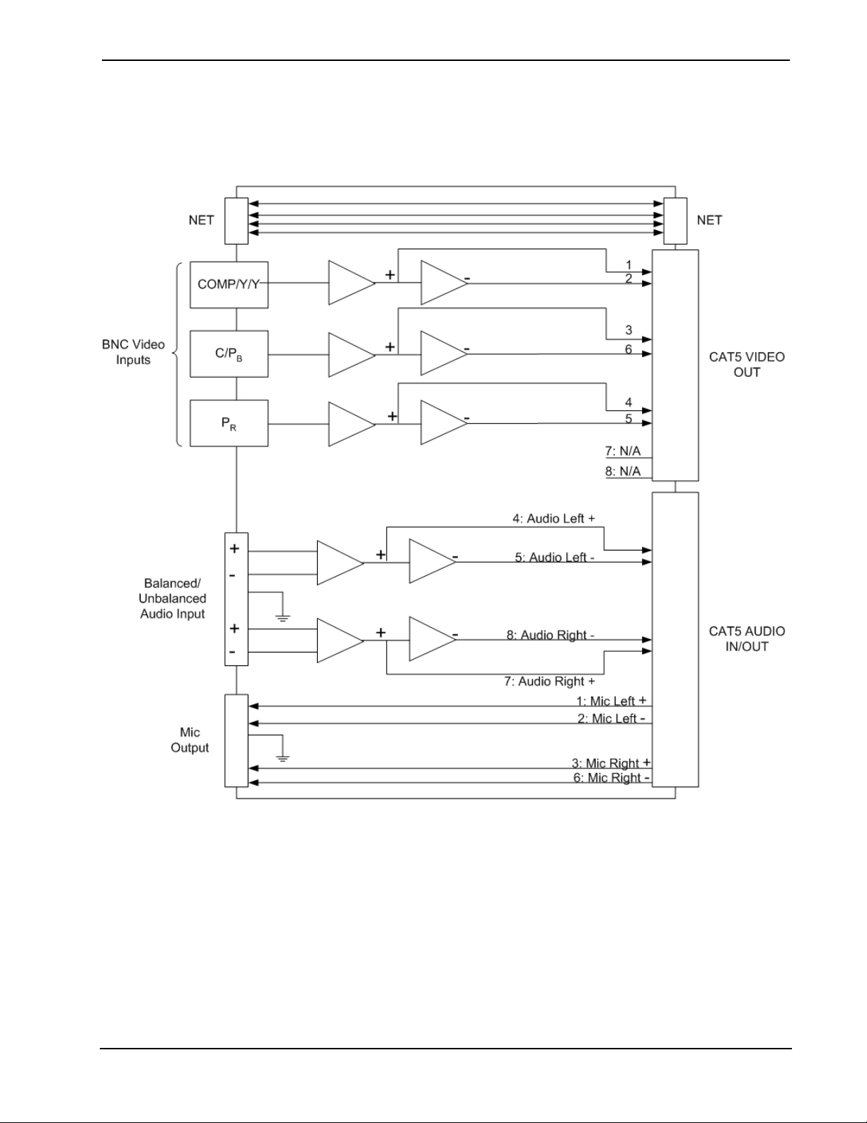
The following block diagram illustrates the function of the
TPMC-CH-IMC.
Block Diagram of the TPMC-CH-IMC
2 • Interface Module: TPMC-CH-IMC Operations Guide - DOC. 6345
Page 7

Crestron TPMC-CH-IMC Interface Module
Specifications
The following table provides a summary of specifications for the
TPMC-CH-IMC.
Specifications of the TPMC-CH-IMC
SPECIFICATION DETAILS
Cresnet Power Usage 2 Watts (0.08 Amp @ 24 VDC)
Video Input
Connector Type
Input Impedance
Input Level
Maximum DC Offset
Video To Panel
Connector Type
Output Impedance
Bandwidth
Audio Input
Connector Type
Input Impedance
Max Input Level
Audio Output
Connector Type
Output Impedance
Max Output Level
Audio To Panel (RJ-45)
Connector Type
Output Impedance
Max Output Level
Operating Temperature
and Humidity
BNC (x3)
75 Ω (internally terminated)
1 V
1.5 V
Nominal, 1.5 V
pp
Maximum
pp
RJ-45
100 Ω (balanced)
100 MHz
5 position, mini-terminal block
10k Ω unbalanced, 20k Ω balanced
2 V
unbalanced, 4 V
RMS
balanced
RMS
5 position, mini-terminal block
600 Ω balanced when connected to
touchpanel
2 V
when connected to touchpanel
RMS
RJ-45
100 Ω balanced
2 V
balanced
RMS
41º to 122º F (5º to 50º C),
10 to 90% Relative Humidity,
non-condensing
Dimensions & Weight Height: 1.29 in (3.26 cm)
Width: 7.30 in (18.54 cm)
Depth: 3.95 in (10.02 cm)
Weight: 9.7 oz (0.28 kg)
Operations Guide - DOC. 6345 Interface Module: TPMC-CH-IMC • 3
Page 8

Interface Module Crestron TPMC-CH-IMC
Physical Description
The TPMC-CH-IMC, shown in the following diagram, is supplied with
the TPMC-15-CH and TPMC-17-CH tilt touchpanel media centers. The
module is housed in a black enclosure with a silk-screened top panel. A
Light Emitting Diode (LED) indicating power, a network connector, and
connectors for video input, audio input, and audio output are located on
one side of the unit. The opposite side provides an RJ-45 video output
connector, an RJ-45 audio input/output connector and a network
connector to the touchpanel. The TPMC-CH-IMC also has a mounting
flange to secure the unit to a mounting surface or the rear of a rack. A
15-foot (4.6 meter) “triamese” cable with connections for network
communications and CAT5 audio and video to the touchpanel is included
with the TPMC-15-CH and TPMC-17-CH touchpanels.
TPMC-CH-IMC
4 • Interface Module: TPMC-CH-IMC Operations Guide - DOC. 6345
Page 9

Crestron TPMC-CH-IMC Interface Module
)
Physical Views of the TPMC-CH-IMC
VIDEO (RED) LABEL
Ø 0.23 in (0.58 cm) 4 PLACES FOR RACK MOUNTING
6.83 in
(17.35 cm)
AUDIO (BLUE) LABEL
7.30 in
(18.54 cm)
3.95 in
(10.02 cm
1.75 in
(4.45 cm)
1.29 in
(3.26 cm)
Ports
There are seven ports that serve various functions on the
TPMC-CH-IMC. Refer to the following diagrams and descriptions of
each port.
NET
This 4-position mini-terminal block connector is used to connect to other
Cresnet peripherals in a system. Another NET connector is located on the
other side of the module. Data and power for the TPMC-CH-IMC are
provided via either connection.
If making network connections to a control system or Cresnet
peripherals, refer to “Network Wiring” on page 8.
Operations Guide - DOC. 6345 Interface Module: TPMC-CH-IMC • 5
Page 10

Interface Module Crestron TPMC-CH-IMC
VIDEO
The video input consists of three BNC connectors for unbalanced video
signals. The component, composite or S-video input signal from an
external video source is connected to these ports.
AUDIO IN
The 5-position mini-terminal block connector mates with the included
connector which is wired to an external audio source and provides
balanced and/or unbalanced audio input. Description of the pinouts is
shown in the following table.
AUDIO IN Pinouts
PIN DESCRIPTION
L + Left Positive
L- Left Negative
G Ground
R + Right Positive
R - Right Negative
AUDIO OUT
The 5-position mini-terminal block connector mates with the included
connector and provides balanced and/or unbalanced microphone output.
Description of the pinouts is shown in the following table.
AUDIO OUT Pinouts
PIN DESCRIPTION
L + Left Positive
L- Left Negative
G Ground
R + Right Positive
R - Right Negative
6 • Interface Module: TPMC-CH-IMC Operations Guide - DOC. 6345
Page 11

Crestron TPMC-CH-IMC Interface Module
VIDEO (To Panel)
This RJ-45 connection mates with the TPMC-15-CH or TPMC-17-CH
touchpanel. This port provides component, composite or S-video input to
the touchpanel over CAT5 wiring. Description of the pinouts is shown in
the following table.
Video Out Pin Assignments
PIN WIRE COLORS
(568B)
1 WHITE/ORANGE WHITE/GREEN + Composite + Luminance + Y
2 ORANGE GREEN - Composite - Luminance - Y
3 WHITE/GREEN WHITE/ORANGE N/A + Chrominance + PB
4 BLUE BLUE N/A N/A + PR
5 WHITE/BLUE WHITE/BLUE N/A N/A - PR
6 GREEN ORANGE N/A - Chrominance - PB
7 WHITE/BROWN WHITE/BROWN N/A N/A N/A
8 BROWN BROWN N/A N/A N/A
WIRE COLORS
(568A)
COMPOSITE
S-VIDEO
COMPONENT
1
To p
1
Front
8
8
AUDIO (To Panel)
This 8-pin RJ-45 connector mates with the TPMC-15-CH or
TPMC-17-CH touchpanel. This port uses CAT5 wiring and provides
audio input to the touchpanel and microphone output from the
touchpanel. A description of the pinouts is shown in the following table.
Audio In/Out Pin Assignments
PIN WIRE COLORS (568B) WIRE COLORS (568A) AUDIO I/O
1 WHITE/ORANGE WHITE/GREEN + Mic Left Out
2 ORANGE GREEN - Mic Left Out
3 WHITE/GREEN WHITE/ORANGE + Mic Right Out
4 BLUE BLUE + Audio Left In
5 WHITE/BLUE WHITE/BLUE - Audio Left In
6 GREEN ORANGE - Mic Right Out
7 WHITE/BROWN WHITE/BROWN + Audio Right In
8 BROWN BROWN - Audio Right In
1
To p
1
Front
Indicator
8
8
This LED, located on the front panel, illuminates when 24 VDC is
supplied to the TPMC-CH-IMC via the NET port.
Operations Guide - DOC. 6345 Interface Module: TPMC-CH-IMC • 7
Page 12

Interface Module Crestron TPMC-CH-IMC
Industry Compliance
As of the date of manufacture, the TPMC-CH-IMC has been tested and
found to comply with specifications for CE marking and standards per
EMC and Radiocommunications Compliance Labelling.
NOTE: This device complies with part 15 of the FCC rules. Operation is
subject to the following two conditions: (1) this device may not cause
harmful interference, and (2) this device must accept any interference
received, including interference that may cause undesired operation.
Setup
Network Wiring
CAUTION: In order to ensure optimum performance over the full range
of your installation topology, Crestron Certified Wire, and only Crestron
Certified Wire, should be used. Failure to do so, may incur additional
charges if support is required to identify performance deficiencies as a
result of using improper wire.
CAUTION: Use only Crestron power supplies for Crestron equipment.
Failure to do so could cause equipment damage or void the Crestron
warranty.
CAUTION: Provide sufficient power to the system. Insufficient power
can lead to unpredictable results or damage to the equipment. Please use
the Crestron Power Calculator (www.crestron.com/calculators
calculate how much power is needed for the system.
CAUTION: Possible equipment damage if miswired.
) to help
NOTE: When installing network wiring, refer to the latest revision of
the wiring diagram(s) appropriate to your specific system configuration,
available from the Crestron website.
8 • Interface Module: TPMC-CH-IMC Operations Guide - DOC. 6345
Page 13

Crestron TPMC-CH-IMC Interface Module
NOTE: Do not power up system until all wiring is verified. Care should
be taken to ensure data (Y, Z) and ground (G) connections are not
crossed when connecting the TPMC-CH-IMC.
When calculating the wire gauge for a particular Cresnet run, the length
of the run and the Cresnet power usage of each Cresnet unit to be
connected must be taken into consideration. If Cresnet units are to be
daisy-chained on the run, the Cresnet power usage of each network unit
to be daisy-chained must be added together to determine the Cresnet
power usage of the entire chain. If the unit is a home-run from a Crestron
system power supply network port, the Cresnet power usage of that unit
is the Cresnet power usage of the entire run. The length of the run in feet
and the Cresnet power usage of the run should be used in the following
resistance equation to calculate the value on the right side of the
equation.
Resistance Equation
R <
40,000
L x P
Where:
R = Resistance (refer to the following table).
L = Length of run (or chain) in feet.
P = Cresnet power usage of entire run (or chain).
The required wire gauge should be chosen such that the resistance value
is less than the value calculated in the resistance equation. Refer to the
table after this paragraph.
Wire Gauge Values
RESISTANCE (R) WIRE GAUGE
4
6
10
15
13
8.7
16
18
20
22
Doubled CAT5
Tripled CAT5
NOTE: All network wiring must consist of two twisted pairs. One
twisted pair is the +24V conductor and the GND conductor. The other
twisted pair is the Y and Z conductors.
NOTE: When daisy-chaining Cresnet units, strip the ends of the wires
carefully to avoid nicking the conductors. Twist together the ends of the
Operations Guide - DOC. 6345 Interface Module: TPMC-CH-IMC • 9
Page 14

Interface Module Crestron TPMC-CH-IMC
wires that share a pin on the network connector, and tin the twisted
connection. Apply solder only to the ends of the twisted wires. Avoid
tinning too far up the wires or the end becomes brittle. Insert the tinned
connection into the Cresnet connector and tighten the retaining screw.
Repeat the procedure for the other three conductors.
NOTE: For larger networks (i.e., greater than 28 network devices), it
may become necessary to add a Cresnet Hub/Repeater (CNXHUB) to
maintain signal quality throughout the network. Also, for networks with
lengthy cable runs, it may be necessary to add a Hub/Repeater after only
20 devices.
CAT5 Wiring
Category 5 (CAT5) wiring is a twisted pair cable designed for Ethernet
networks. These networks operate at speeds of up to 100 Megabits per
second (Mbps) using the 100baseT standard. Crestron takes advantage of
this specification for a variety of audio and video applications.
Crestron recommends using CresCAT, CresCAT-D, or CresCAT-Q
wiring solutions.
The following chart shows the maximum recommended cable lengths for
various signal formats.
Recommended Maximum Cable Lengths for Audio/Video via CAT5
FORMAT MAXIMUM DISTANCE
Composite 750 feet
S-Video 750 feet
Component 500 feet
Audio 1000 feet (balanced)*
* The maximum distance for CAT5 audio is limited to approximately 15 feet
when connecting the AUDIO OUT port to a device with an unbalanced input.
If the AUDIO OUT port connects to a device with balanced inputs or no
device is connected, the maximum cable length for CAT5 audio is 1000 feet.
For more information, refer to the latest version of the Crestron CAT5
Wiring Reference Guide (Doc. 6137).
10 • Interface Module: TPMC-CH-IMC Operations Guide - DOC. 6345
Page 15

Crestron TPMC-CH-IMC Interface Module
Hardware Hookup
The TPMC-CH-IMC serves as an interface between the touchpanel and
the Cresnet system. Refer to the illustration after this paragraph for
proper connections; apply power last. When making network connections
to a control system or Cresnet peripherals, refer to “Network Wiring” on
page 8. It is not necessary to make connections to a video source unless a
video window object resides on a page within the uploaded Crestron
VisionTools
Hardware Hookup for the TPMC-CH-IMC
®
Pro-e (VT Pro-e) project.
AUDIO (TO PANEL):
BALANCED AUDIO OUT AND MIC IN
OVER CAT5 (BLUE)
VIDEO (TO PANEL):
BALANCED VIDEO OUT OVER CAT5
(RED)
CRESNET (TO PANEL):
SENDS AND RECEIVES CRESNET
SIGNALS BETWEEN TOUCHPANEL
AND CONTROL SYSTEM
PROVIDES LINE-LEVEL BALANCED
UNBALANCED AUDIO SOURCES
UNBALANCED “P
UNBALANCED “C” FOR S-VIDEO,
OR UNBALANCED “P
UNBALANCED COMPOSITE VIDEO,
UNBALANCED “Y” FOR S-VIDEO,
OR UNBALANCED “Y” FOR YP
TO CONTROL SYSTEM AND
OTHER CRESNET DEVICES
AUDIO OUT:
MICROPHONE AUDIO
AUDIO IN:
LINE-LEVEL, BALANCED &
PR:
” FOR YPBP
R
C/PB:
” FOR YPBP
B
COMP/Y/Y:
CRESNET:
R
BPR
R
A triamese cable that is included with the touchpanel has an RJ-45
connector with a blue cover to match the blue label on the
TPMC-CH-IMC and an RJ-45 connector with a red cover to match the
red label on the TPMC-CH-IMC. The cable also has a 4-position miniterminal block connector for making a network connection between the
touchpanel and the TPMC-CH-IMC.
The TPMC-CH-IMC can send and receive balanced or unbalanced audio
signals. Refer to the following diagrams when connecting balanced and
unbalanced signals to the TPMC-CH-IMC.
Operations Guide - DOC. 6345 Interface Module: TPMC-CH-IMC • 11
Page 16

Interface Module Crestron TPMC-CH-IMC
Wiring for Audio Input: Unbalanced (left) and Balanced (right)
L R
+ - G + -
L R
+ - G + -
Shield
+
Left
+
Shield
Jumpers
+
Right
Shield
+
Wiring for Audio Output: Unbalanced (left) and Balanced (right)
L R
+ - G + -
Shield
Shield
+
+
Right
AMP
Left
L R
+ - G + -
Shield
+
+
Right
AMP
Left
12 • Interface Module: TPMC-CH-IMC Operations Guide - DOC. 6345
Page 17

Crestron TPMC-CH-IMC Interface Module
Problem Solving
Troubleshooting
The following table provides corrective action for possible trouble
situations. If further assistance is required, please contact a Crestron
customer service representative.
TPMC-CH-IMC Troubleshooting
TROUBLE POSSIBLE
CAUSE(S)
Touchpanel
does not
function.
Video
window on
touchpanel
has no
display.
Touchpanel is not
communicating to
the network.
Improper video
connection.
Incorrect video
format selection.
Incorrect VT Pro-e
project file loaded.
Damaged connector
pins.
CORRECTIVE ACTION
Use Viewport (via SIMPL
Windows or VT Pro-e) to poll
the network. Verify network
connection to the touchpanel.
Verify proper connections on
the touchpanel and
TPMC-CH-IMC.
Select the proper video input
configuration in the
touchpanel configuration
SETUP MENU.
Make sure that video window
object resides in project, recompile, and reload.
Inspect connector pins. If
bent, carefully re-straighten.
If broken, contact Crestron
customer service.
No Audio
from
touchpanel
speakers.
Operations Guide - DOC. 6345 Interface Module: TPMC-CH-IMC • 13
Improper audio
connection.
Verify proper connections on
the touchpanel and
TPMC-CH-IMC.
Page 18

Interface Module Crestron TPMC-CH-IMC
Further Inquiries
If you cannot locate specific information or have questions after
reviewing this guide, please take advantage of Crestron's award winning
customer service team by calling the Crestron corporate headquarters at
1-888-CRESTRON [1-888-273-7876]. For assistance in your local time
zone, refer to the Crestron website (www.crestron.com
Crestron worldwide offices.
You can also log onto the online help section of the Crestron website to
ask questions about Crestron products. First-time users will need to
establish a user account to fully benefit from all available features.
) for a listing of
Future Updates
As Crestron improves functions, adds new features, and extends the
capabilities of the interface module, additional information may be made
available as manual updates. These updates are solely electronic and
serve as intermediary supplements prior to the release of a complete
technical documentation revision.
Check the Crestron website periodically for manual update availability
and its relevance. Updates are identified as an “Addendum” in the
Download column.
14 • Interface Module: TPMC-CH-IMC Operations Guide - DOC. 6345
Page 19

Crestron TPMC-CH-IMC Interface Module
Return and Warranty Policies
Merchandise Returns / Repair Service
1. No merchandise may be returned for credit, exchange, or service without prior authorization from
CRESTRON. To obtain warranty service for CRESTRON products, contact the factory and request an
RMA (Return Merchandise Authorization) number. Enclose a note specifying the nature of the
problem, name and phone number of contact person, RMA number, and return address.
2. Products may be returned for credit, exchange, or service with a CRESTRON Return Merchandise
Authorization (RMA) number. Authorized returns must be shipped freight prepaid to CRESTRON, 6
Volvo Drive, Rockleigh, N.J., or its authorized subsidiaries, with RMA number clearly marked on the
outside of all cartons. Shipments arriving freight collect or without an RMA number shall be subject to
refusal. CRESTRON reserves the right in its sole and absolute discretion to charge a 15% restocking
fee, plus shipping costs, on any products returned with an RMA.
3. Return freight charges following repair of items under warranty shall be paid by CRESTRON,
shipping by standard ground carrier. In the event repairs are found to be non-warranty, return freight
costs shall be paid by the purchaser.
CRESTRON Limited Warranty
CRESTRON ELECTRONICS, Inc. warrants its products to be free from manufacturing defects in materials and
workmanship under normal use for a period of three (3) years from the date of purchase from CRESTRON,
with the following exceptions: disk drives and any other moving or rotating mechanical parts, pan/tilt heads and
power supplies are covered for a period of one (1) year; touchscreen display and overlay components are
covered for 90 days; batteries and incandescent lamps are not covered.
This warranty extends to products purchased directly from CRESTRON or an authorized CRESTRON dealer.
Purchasers should inquire of the dealer regarding the nature and extent of the dealer's warranty, if any.
CRESTRON shall not be liable to honor the terms of this warranty if the product has been used in any
application other than that for which it was intended, or if it has been subjected to misuse, accidental damage,
modification, or improper installation procedures. Furthermore, this warranty does not cover any product that
has had the serial number altered, defaced, or removed.
This warranty shall be the sole and exclusive remedy to the original purchaser. In no event shall CRESTRON
be liable for incidental or consequential damages of any kind (property or economic damages inclusive) arising
from the sale or use of this equipment. CRESTRON is not liable for any claim made by a third party or made by
the purchaser for a third party.
CRESTRON shall, at its option, repair or replace any product found defective, without charge for parts or labor.
Repaired or replaced equipment and parts supplied under this warranty shall be covered only by the unexpired
portion of the warranty.
Except as expressly set forth in this warranty, CRESTRON makes no other warranties, expressed or implied,
nor authorizes any other party to offer any warranty, including any implied warranties of merchantability or
fitness for a particular purpose. Any implied warranties that may be imposed by law are limited to the terms of
this limited warranty. This warranty statement supercedes all previous warranties.
Trademark Information
All brand names, product names, and trademarks are the sole property of their respective owners. Windows is a registered trademark of
Microsoft Corporation. Windows95/98/Me and WindowsNT/2000 are trademarks of Microsoft Corporation.
Operations Guide - DOC. 6345 Interface Module: TPMC-CH-IMC • 15
Page 20

Crestron Electronics, Inc. Operations Guide - DOC. 6345
15 Volvo Drive Rockleigh, NJ 07647 (2012969)
Tel: 888.CRESTRON 04.05
Fax: 201.767.7576 Specifications subject to
www.crestron.com change without notice.
 Loading...