


Crestron TPMC-8X
Isys i/O™ 8.4” WiFi Touchpanel
Operations Guide

This document was prepared and written by the Technical Documentation department at:
Crestron Electronics, Inc.
15 Volvo Drive
Rockleigh, NJ 07647
1-888-CRESTRON
®
Windows
, Windows® XP and Windows® Vista are registered trademarks of Microsoft Corporation in the United States and other countries.
All brand names, product names and trademarks are the property of their respective owners.
©2008 Crestron Electronics, Inc.

Crestron TPMC-8X Isys i/O™ 8.4” WiFi Touchpanel
Contents
Isys i/O™ 8.4” WiFi Touchpanel: TPMC-8X 1
Introduction ...............................................................................................................................1
Features and Functions................................................................................................ 1
Specifications ..............................................................................................................4
Physical Description.................................................................................................... 7
Industry Compliance .................................................................................................10
Setup ........................................................................................................................................ 11
Identity Code ............................................................................................................. 11
Internal Battery Switch.............................................................................................. 11
Configuring the Touchpanel...................................................................................... 12
Hardware Hookup .....................................................................................................51
Recommended Cleaning............................................................................................ 52
Programming Software............................................................................................................53
Earliest Version Software Requirements for the PC .................................................53
Programming with Crestron SystemBuilder.............................................................. 53
Programming with SIMPL Windows........................................................................ 53
Programming with VisionTools Pro-e....................................................................... 55
Embedded Applications.............................................................................................58
Defaults for Embedded Windows Applications ........................................................ 59
Programming Embedded Windows Applications......................................................60
Example Program...................................................................................................... 60
Uploading and Upgrading........................................................................................................ 61
Establishing Communication.....................................................................................61
Programs, Projects and Firmware.............................................................................. 61
Program Checks ........................................................................................................62
Operation .................................................................................................................................63
Power Options ........................................................................................................... 63
Charging the Internal Battery .................................................................................... 64
Security Infrastructure............................................................................................... 64
Problem Solving ......................................................................................................................66
Troubleshooting......................................................................................................... 66
Reference Documents................................................................................................67
Further Inquiries........................................................................................................67
Future Updates ..........................................................................................................68
Appendix A: TPMC-8X Security Pack (Atheros) ..................................................................69
Appendix B: TPMC-8X Security Pack (Intel PROSet).......................................................... 73
Appendix C: TPMC-8X Multi-Language Pack ...................................................................... 78
Software License Agreement................................................................................................... 79
Return and Warranty Policies.................................................................................................. 81
Merchandise Returns / Repair Service ......................................................................81
CRESTRON Limited Warranty.................................................................................81
Microsoft® Windows XP® Embedded End User License Agreement ................................... 82
Operations Guide – DOC. 6539B Contents • i


Crestron TPMC-8X Isys i/O™ 8.4” WiFi Touchpanel
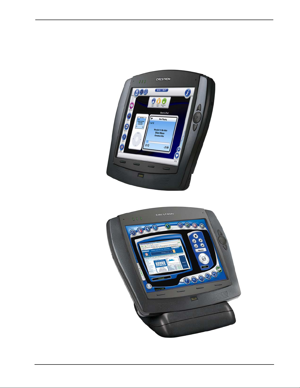
Isys i/O™ 8.4” WiFi Touchpanel:
TPMC-8X
Introduction
Features and Functions
• Stylish and compact ergonomic design
• 8.4 in (21.3 cm) active matrix touchscreen display with 800 x 600
* Reserved for future applications. When uploading new firmware, review release notes to see if this
Advanced Ergonomics
resolution
• 16-bit Isys i/O™ graphics with Synapse™ image rendering algorithm
• 802.11a/b/g WiFi 2-way wireless communications
• Windows
• Onboard PC applications for Web browsing, streaming media,
conferencing, VoIP and remote desktop
• Built-in stereo speakers and dual microphones
• Wireless video from network cameras and servers
• 5-way thumbpad and four “softkey” buttons
• Includes stylus with onboard storage slot
• Built-in biometric fingerprint scanner
• Built-in Bluetooth
• Internal Li-Ion battery pack included
• External “booster” battery pack available
• Optional desktop and wall mount docking stations
feature is available.
®
XP Embedded operating system
®
technology*
Incredibly thin and compact, the TPMC-8X is brilliantly designed to provide a
powerful mobile control solution that is easy to hold and intuitive to use. Its
magnesium alloy enclosure presents a sleek, modern appearance that is both rugged
and lightweight.
Tactile Controls
An integrated 5-way thumbpad and up/down arrow buttons add quick access and
tactile response for controlling functions ranging from simple volume adjustment
Operations Guide – DOC. 6539B Isys i/O™ 8.4” WiFi Touchpanel: TPMC-8X • 1

Isys i/O™ 8.4” WiFi Touchpanel Crestron TPMC-8X
and channel selection to on-screen menu navigation or even pan/tilt camera control.
Four additional “softkeys” are positioned below the touchscreen, programmable for
context sensitive menu functions. A stylus is even included for use with the on-
screen keyboard, conveniently stowed in its own storage slot.
Isys®
Isys power and beauty are infused throughout Crestron’s entire touchpanel lineup.
Under the hood, the TPMC-8X offers vibrant 16-bit color depth to produce
incredible 3D graphics, high-res images, translucence, dynamic text and graphics,
full-motion animations, multimode objects and dramatic transition effects, all with
astonishing speed.
Synapse™
Crestron’s exclusive Synapse Image Rendering Algorithm enables system
programmers to produce amazing graphics – faster and easier. Advanced antialiasing
delivers crisper, sharper objects and text. Enhanced 3D effects add new depth and
style. And because Synapse is native to the touchpanel, memory requirements and
upload time are substantially reduced.
Bluetooth® Technology
Built-in Bluetooth enable the use of a wireless mouse, keyboard and other devices. A
USB 2.0 port is also provided for connecting wired devices.
NOTE: Reserved for future applications. When uploading new firmware, review
release notes to see if this feature is available.
Biometric Scanner
The built-in fingerprint scanner unleashes a whole new level of convenience and
security, allowing individual users to be identified instantly and logged on
automatically. With just the touch of a fingertip, each user can be presented with a
unique graphical interface with its own set of preferences, access privileges and even
its own look through the use of touchpanel “skins”.
WiFi Wireless
Integrated 802.11a/b/g WiFi technology with WEP encryption delivers secure, high-
speed two-way wireless performance across wireless LANs, affording mobile
freedom and seamless communications with Crestron control systems, computers,
digital media servers and other IP-based devices.
Embedded PC
The power of Isys i/O is in its embedded PC engine, combining rock solid
touchpanel performance with built-in Windows Media
Internet Explorer, Adobe
PowerPoint
or boardroom, the TPMC-8X provides everything needed for enjoying online music
and movies, viewing Web pages and other documents without necessitating a
separate computer.
®
document viewers. While simultaneously controlling your home theater
®
Acrobat® Reader and Microsoft Word, Excel and
®
Player and RealPlayer®,
The TPMC-8X also lets you access data and run applications on other computers via
Remote Desktop, while onboard NetMeeting
conferencing and voice-over-IP capabilities right on the touchpanel. The VNC
viewer supports enhanced cross-platform interaction with remote computers over the
2 • Isys i/O™ 8.4” WiFi Touchpanel: TPMC-8X Operations Guide – DOC. 6539B
®
and Skype™ applications enable

Crestron TPMC-8X Isys i/O™ 8.4” WiFi Touchpanel
network or Internet, allowing full access and control of desktop applications with
live presentation capability. Support for Yahoo! Widgets affords an easy solution for
integrating everything from calendars and clocks to stock tickers, weather forecasts,
news feeds and thousands of other fun and useful utilities.
Built on the Windows XP Embedded operating system, the TPMC-8X delivers a
powerful and secure platform for touchpanel control with integrated PC capabilities.
Programmatic control erases the lines between control system and PC, allowing
programmers to customize each application’s behavior within the touchpanel
environment to create a truly powerful and user-friendly interface.
Wireless Video
For entertainment or surveillance, the TPMC-8X makes it easy to view security
cameras, movies and other video sources right on the touchscreen. In addition to the
wide range of formats supported by its embedded media player applications, the
TPMC-8X also features native support for viewing streaming video from Axis
Network Video cameras and servers.
Audio Features
Built-in stereo speakers, dual integrated microphones and a stereo headphone output
provide full audio functionality to complement the TPMC-8X’s touchpanel, video
and computer capabilities. Customized WAV files can be loaded on the touchpanel
to add dimension to the touchscreen graphics with personalized sounds, button
feedback and voice prompts.
Li-Ion Rechargeable Batteries
A field-replaceable Lithium Ion battery pack onboard the TPMC-8X provides fast
charging, long lasting wireless operation without the “memory” issues typical of
other rechargeable batteries. An external “booster” battery pack is also available,
which clips neatly to the rear of the touchpanel without tools, adding 0.75 inch depth
and non-slip rubber feet resulting in a fixed tilt angle of 7 degrees.
Docking Station Options
Optional desktop or wall mount docking stations afford a choice of convenient
charging solutions, adding 10/100 Ethernet for direct connection to a wired LAN,
plus two USB ports for mouse and keyboard. The desktop dock allows the
touchpanel to be operated at a 37 degree angle, while the wall mount model provides
a secure, flush look.
Operations Guide – DOC. 6539B Isys i/O™ 8.4” WiFi Touchpanel: TPMC-8X • 3

Isys i/O™ 8.4” WiFi Touchpanel Crestron TPMC-8X
Specifications
Specifications for the TPMC-8X are listed in the following table.
TPMC-8X Specifications
SPECIFICATION DETAILS
Touchscreen Display
Display Type TFT active matrix color LCD
Size 8.4 inch (21.3 cm) diagonal
Aspect Ratio 4:3 SVGA
Resolution 800 x 600 pixels
Brightness 200 nits
Contrast 500:1
Color Depth 18-bit, 262k colors
Illumination Edgelit fluorescent
Viewing Angle1 ±65º horizontal, +65º/-45º vertical
Touchscreen Resistive membrane
Memory
DDR SDRAM 512 MB
Flash
Compact Flash
Maximum Project Size 190 MB
Operating System Microsoft® Windows® XP Embedded
Graphic Engine
Embedded PC Applications3
Wireless3
RF Transceiver
Range
Bluetooth7 Bluetooth® V1.2 Class 1 built in
1 GB, expandable via Compact Flash card
slot
Accepts up to 4 GB CF+ Type II Compact
Flash card (not included)
Isys i/O engine, 16-bit non-palette graphics;
65,536 colors; Synapse image rendering
algorithm; multi-mode objects; dynamic
menu objects; dynamic graphics2; PNG
translucence; 24 fps animation; transition
effects
Microsoft Internet Explorer w/Macromedia
®
Flash
plug-in, Windows Media® Player,
®
RealPlayer
MJPEG viewer, Remote Desktop,
NetMeeting
Java™ Runtime, DirectX
Widgets
, Axis® Media Control, Crestron
®
, Skype™4, VNC viewer5,
6
, Adobe® Acrobat® Reader,
®
, Yahoo!
®
WordPad and viewers for MS Word, Excel
and PowerPoint®.
IEEE 802.11a/b/g WiFi, 5 or 2.4 GHz twoway RF, static IP or dynamic IP via DHCP,
64 and 128-bit WEP encryption, requires
third-party 802.11a/b/g wireless access
point and Ethernet enabled Crestron
2-Series control system
30 feet (10 m) @ 54 Mbps; range and
speed vary based upon environmental
conditions
(Continued on following page)
4 • Isys i/O™ 8.4” WiFi Touchpanel: TPMC-8X Operations Guide – DOC. 6539B

Crestron TPMC-8X Isys i/O™ 8.4” WiFi Touchpanel
TPMC-8X Specifications (Continued)
SPECIFICATION DETAILS
Video
Streaming/File Formats
MPEG4 and MJPEG via Axis
®
Media
Control or Crestron MJPEG Viewer, plus all
formats supported by the embedded media
player applications
3
Audio
Hardware Features
Dual onboard microphones, built-in stereo
speakers, stereo headphone output
Streaming/File Formats
As supported by the embedded media
player applications3
Audio Feedback (WAV)
8 & 16 bit PCM, mono & stereo,
8 – 44.1 kHz sampling rates
Amplification Stereo, 1.1 Watts per channel
Battery
Internal Battery Type Lithium Ion, 7.4 Volt, 2200 mAh (included)
Usage per Charge8
~1.5 hours continuous, >9 hours under
normal use with standby/power down
activated
Charging Time ~2 hours (~2.5 - 3 hours when in use)
Power Requirements
Touchpanel 42 Watts (3.5 Amps) @ 12 Volts DC
Universal Power
100~240 VAC 50/60 Hz
Supply/Charger (included)
Default IP ID9 03
Minimum 2-Series Control
System Update File
10, 11
Version 3.137 or later
Environmental
Operating Temperature 32º to 104ºF (0º to 40ºC)
Storage Temperature 14º to 140ºF (-10º to 60ºC)
Humidity 10% to 90% RH (non-condensing)
Enclosure
Magnesium alloy case with plastic buttons,
stylus storage slot (stylus included), integral
docking station port
Dimensions
Height 8.21 in (20.85 cm)
Width 9.69 in (24.60 cm)
Depth 0.92 in (2.32 cm)
Weight (with internal battery) 1.98 lbs (0.90 kg)
Available Accessories
TPMC-8X-DS Desktop Docking Station/Charger
TPMC-8X-DSW Wall Mount Docking Station/Charger
TPMC-8X-BTP Internal Battery Pack
TPMC-8X-BTPE External Battery Pack
1. Optimum viewing angle for best contrast is 37º.
2. By design, the panel will not load dynamic graphics if they are located on a password protected FTP
or HTTP server.
Operations Guide – DOC. 6539B Isys i/O™ 8.4” WiFi Touchpanel: TPMC-8X • 5

Isys i/O™ 8.4” WiFi Touchpanel Crestron TPMC-8X
3. Contact Crestron for a current list of compatible devices and embedded applications. To ensure
reliable performance, new device drivers and applications are available only from Crestron through
firmware updates.
4. The default minimum window size for Skype™ can not be overridden.
5. The supported VNC viewer is UltraVNC version 1.0.2. Other VNC viewers may work but are not
guaranteed.
6. The TPMC-8X supports Yahoo! Widgets version 4.0 or later.
7. Reserved for future applications. When uploading new firmware, review release notes to see if this
feature is available.
8. Up to 3.5 hours continuous, > 20 hours under normal use with standby/power down activated, when
using external battery pack option, with screen brightness set to 65%, standby set to 1 minute, power
down set to 2 minutes, waking the panel five time per hour. Actual usage can vary depending on your
settings.
9. Refer to “Identity Code” on page 11 for details.
10. The latest software versions can be obtained from the Crestron website. Refer to the NOTE following
these footnotes.
11. Crestron 2-Series control systems include the AV2 and PRO2. Consult the latest Crestron Product
Catalog for a complete list of 2-Series control systems.
NOTE: Crestron software and any files on the website are for authorized Crestron
dealers and Crestron Authorized Independent Programmers (CAIP) only. New users
may be required to register to obtain access to certain areas of the site (including the
FTP site).
6 • Isys i/O™ 8.4” WiFi Touchpanel: TPMC-8X Operations Guide – DOC. 6539B
Crestron TPMC-8X Isys i/O™ 8.4” WiFi Touchpanel
Physical Description
This section provides information on the connections, controls and indicators
available on your TPMC-8X.
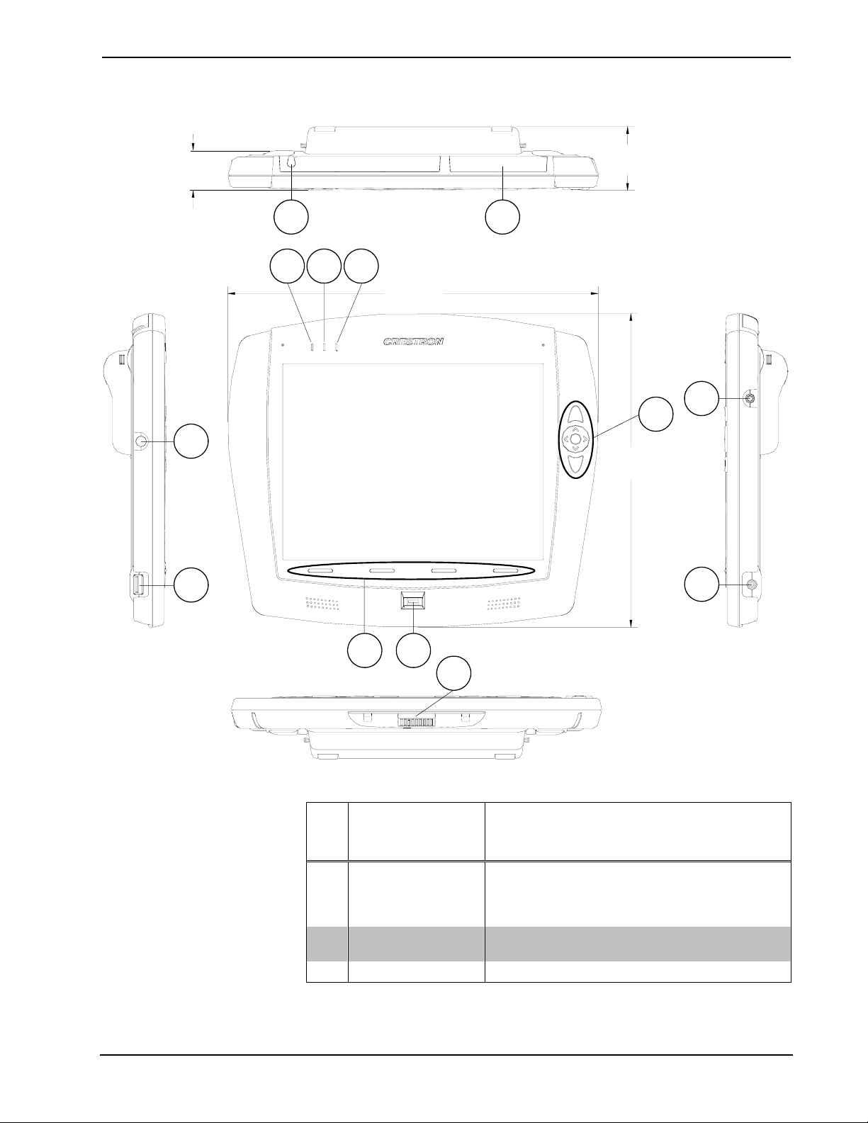
TPMC-8X Physical View
TPMC-8X Physical View (on optional TPMC-8X-DS Desktop Docking Station/Charger)
Operations Guide – DOC. 6539B Isys i/O™ 8.4” WiFi Touchpanel: TPMC-8X • 7
Isys i/O™ 8.4” WiFi Touchpanel Crestron TPMC-8X
TPMC-8X Overall Dimensions (shown with optional TPMC-8X-BTPE External Battery Pack attached)
0.92 in
(2.32 cm)
6
1.67 in
(4.24 cm)
1 2
3 4 5
9.69 in
(24.60 cm)
8
7
8.21 in
(20.85 cm)
9
12
1110
13
Connectors, Controls & Indicators
# CONNECTORS,
CONTROLS &
INDICATORS
1 STYLUS
2 MEMORY SLOT
3 POWER LED (Green) Indicates touchpanel power is on.
Used to “tap” or to do “select and drag” functions
just as you would using a mouse. It is also used
to “type” on the input panel “keyboard” when
entering text or commands.
(1) CF+ Type II Compact Flash card slot for
memory expansion
DESCRIPTION
(Continued on following page)
8 • Isys i/O™ 8.4” WiFi Touchpanel: TPMC-8X Operations Guide – DOC. 6539B
Crestron TPMC-8X Isys i/O™ 8.4” WiFi Touchpanel
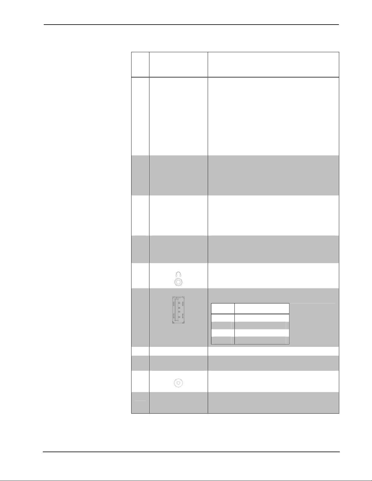
Connectors, Controls & Indicators (Continued)
# CONNECTORS,
DESCRIPTION
CONTROLS &
INDICATORS
4 BATTERY LED
5 WIFI LED
6 POWER BUTTON
7
HARD
PUSHBUTTONS &
THUMBPAD1
8
HEADPHONES
9
USB2
4
3
2
1
10 BUTTONS (4) “softkey” buttons, programmable
11
FINGERPRINT
SCANNER
12
12V 3.5A
13
DOCKING
STATION
CONNECTOR
1. For programming details, refer to “Hard Buttons” on page 31.
2. Only generic USB devices (i.e. simple keyboard, mouse and external storage) should be used with the
TPMC-8X. Any complex USB devices (e.g. a storage device with a built-in fingerprint scanner) will
not have the proper support on the panel.
Indicates status of batteries (internal and
external). When AC is offline and the external
battery is connected, the panel will use the
external battery before using the internal battery
and the LED will remain solid green. Once the
internal battery is in use, the LED will remain
solid green if battery level is above 25% (±3%) of
full charge, solid yellow if charge drops to 25%
(±3%) and blinking yellow if battery level drops to
10% (±3%). When AC is online and battery is
charging, the LED will be blinking green until
charge is 100%.
Indicates status of panel’s WiFi connection:
Solid green – communicating with a wireless
access point (WAP)
Blinking green – searching for a WAP
Off – no wireless communication (unit is in power
down mode or power is off).
Press to turn touchpanel power on. Press again
to put panel in power down mode. Press to
restore full on mode. Press and hold for four
seconds to turn power off. (The recommended
method for shutting down the touchpanel is to
press the Shut Down button on the setup menu.)
These hard pushbuttons and the 5-way thumb
pad are programmable and can provide tactile
control of many functions such as audio volume
and channel selection.
(1) 3.5 mm TRS mini phone jack;
Output power: 12 mW per channel;
Minimum impedance: 32 Ω
(1) USB 2.0 Type A female
PIN DESCRIPTION
1 +5 VDC
2 Data -
3 Data +
4 Ground
Biometric fingerprint scanner for user
identification and log on.
(1) DC power jack (power pack included);
power pack can also be used to charge internal
battery.
Mates with TPMC-8X-DS or
TPMC-8X-DSW Docking Station/Charger (sold
separately).
Operations Guide – DOC. 6539B Isys i/O™ 8.4” WiFi Touchpanel: TPMC-8X • 9

Isys i/O™ 8.4” WiFi Touchpanel Crestron TPMC-8X
Industry Compliance
As of the date of manufacture, the TPMC-8X has been tested and found to comply
with specifications for CE marking and standards per EMC and
Radiocommunications Compliance Labelling.
NOTE: This device complies with part 15 of the FCC rules. Operation is subject to
the following two conditions: (1) this device may not cause harmful interference and
(2) this device must accept any interference received, including interference that may
cause undesired operation.
This equipment has been tested and found to comply with the limits for a Class B
digital device, pursuant to part 15 of the FCC Rules. These limits are designed to
provide reasonable protection against harmful interference in a residential
installation. This equipment generates, uses and can radiate radio frequency energy
and if not installed and used in accordance with the instructions, may cause harmful
interference to radio communications. However, there is no guarantee that
interference will not occur in a particular installation. If this equipment does cause
harmful interference to radio or television reception, which can be determined by
turning the equipment off and on, the user is encouraged to try to correct the
interference by one or more of the following measures:
Reorient or relocate the receiving antenna.
Increase the separation between the equipment and receiver.
Connect the equipment into an outlet on a circuit different from that to
which the receiver is connected.
Consult the dealer or an experienced radio/TV technician for help.
10 • Isys i/O™ 8.4” WiFi Touchpanel: TPMC-8X Operations Guide – DOC. 6539B
Crestron TPMC-8X Isys i/O™ 8.4” WiFi Touchpanel
Setup
Identity Code
The IP ID is set within the TPMC-8X’s table using Crestron Toolbox™. For
information on setting an IP table, refer to the Crestron Toolbox help file. The IP IDs
of multiple TPMC-8X devices in the same system must be unique
When setting the IP ID, consider the following:
• The IP ID of each unit must match an IP ID specified in the SIMPL™
Windows
• Each device using IP to communicate with a control system must have a
unique IP ID.
®
program.
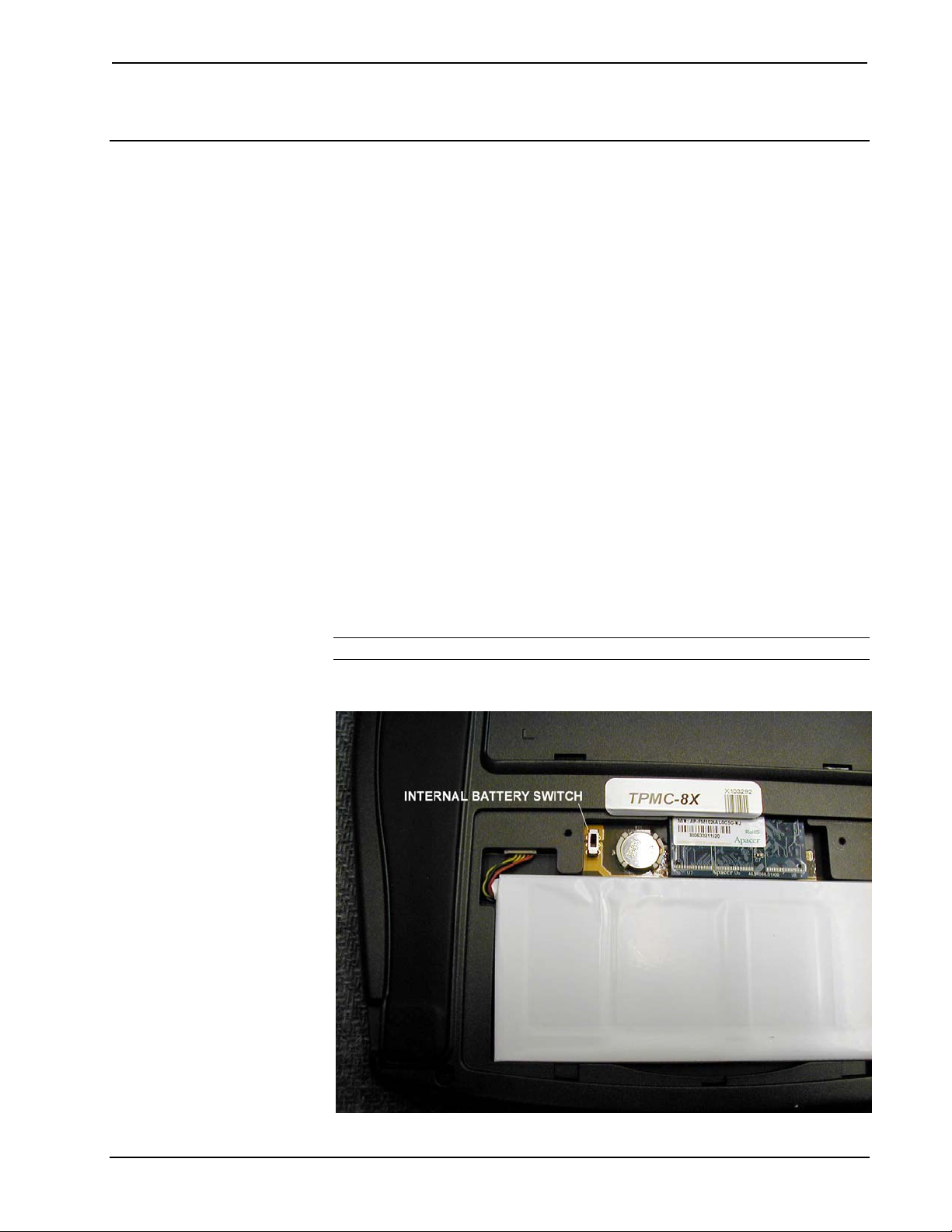
Internal Battery Switch
The TPMC-8X comes with a TPMC-8X-BTP Internal Battery Pack installed. To
prevent internal battery drain during shipment or long-term storage, the
TPMC-8X has a battery switch inside the battery compartment. To use the internal
battery, remove the battery compartment cover by first removing the two screws that
attach it to the back of the touchpanel. Move the switch to the up (on) position and
re-attach the battery compartment cover.
To conserve internal battery power when the unit will not be used for extended
periods, move the switch to the down (off) position.
NOTE: The internal battery can still be charged with the switch in the off position.
TPMC-8X Internal Battery Switch
Operations Guide – DOC. 6539B Isys i/O™ 8.4” WiFi Touchpanel: TPMC-8X • 11
Isys i/O™ 8.4” WiFi Touchpanel Crestron TPMC-8X
Configuring the Touchpanel
NOTE: The only connection required to configure the touchpanel is power
(supplied from the internal battery, external battery or the included power pack).
The TPMC-8X is configured from the setup menu.
NOTE: If no project has been loaded or if an invalid project has been loaded, the
touchpanel displays an error message and defaults to the setup menu screen.
If a project is running, the setup menu can be accessed using one of three methods.
Via the Softkeys
Via USB Keyboard
Press the four softkeys at the bottom of the touchpanel in sequence, from left to right
and again from left to right (i.e. press 1, 2, 3, 4, 1, 2, 3, 4) within a 10 second period.
1. Attach a USB keyboard (refer to “Hardware Hookup” on page 51 for
details).
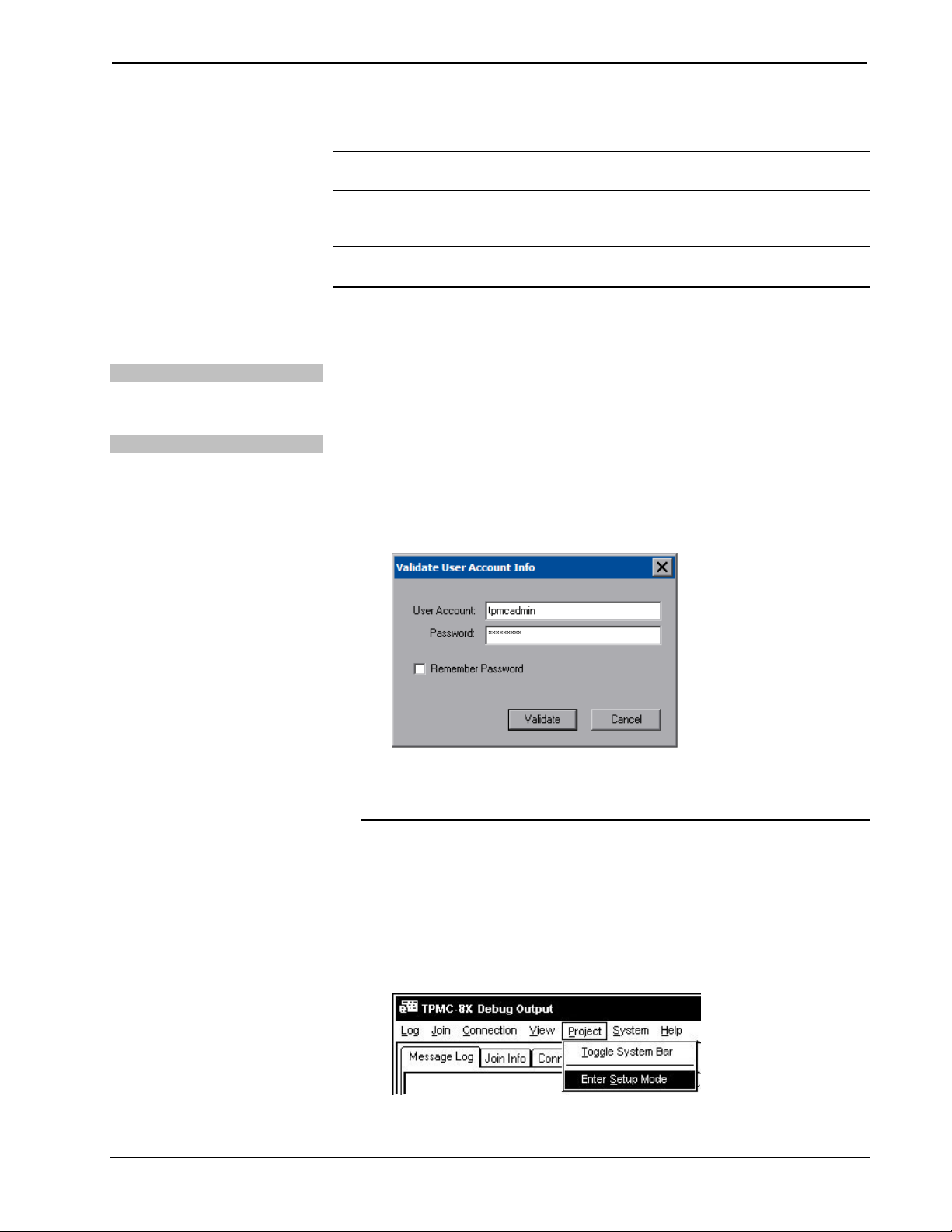
2. Open the “Validate User Account Info” window (shown below) by pressing
Ctrl+Alt+Shift on the keyboard.
“Validate User Account Info” Window
3. Enter the user account tpmcadmin, and the password tpmcadmin and click
Validate.
NOTE: The password is case sensitive. After logging in, the password can be
changed from the “Security” window. Refer to “Security” on page 14 for more
information.
4. When the “TPMC-8X Debug Output” window appears (shown below),
select Project | Enter Setup Mode to enter the setup menu (refer to “Setup
Menu Details” which starts on page 14).
“TPMC-8X Debug Output” Window
12 • Isys i/O™ 8.4” WiFi Touchpanel: TPMC-8X Operations Guide – DOC. 6539B
Crestron TPMC-8X Isys i/O™ 8.4” WiFi Touchpanel
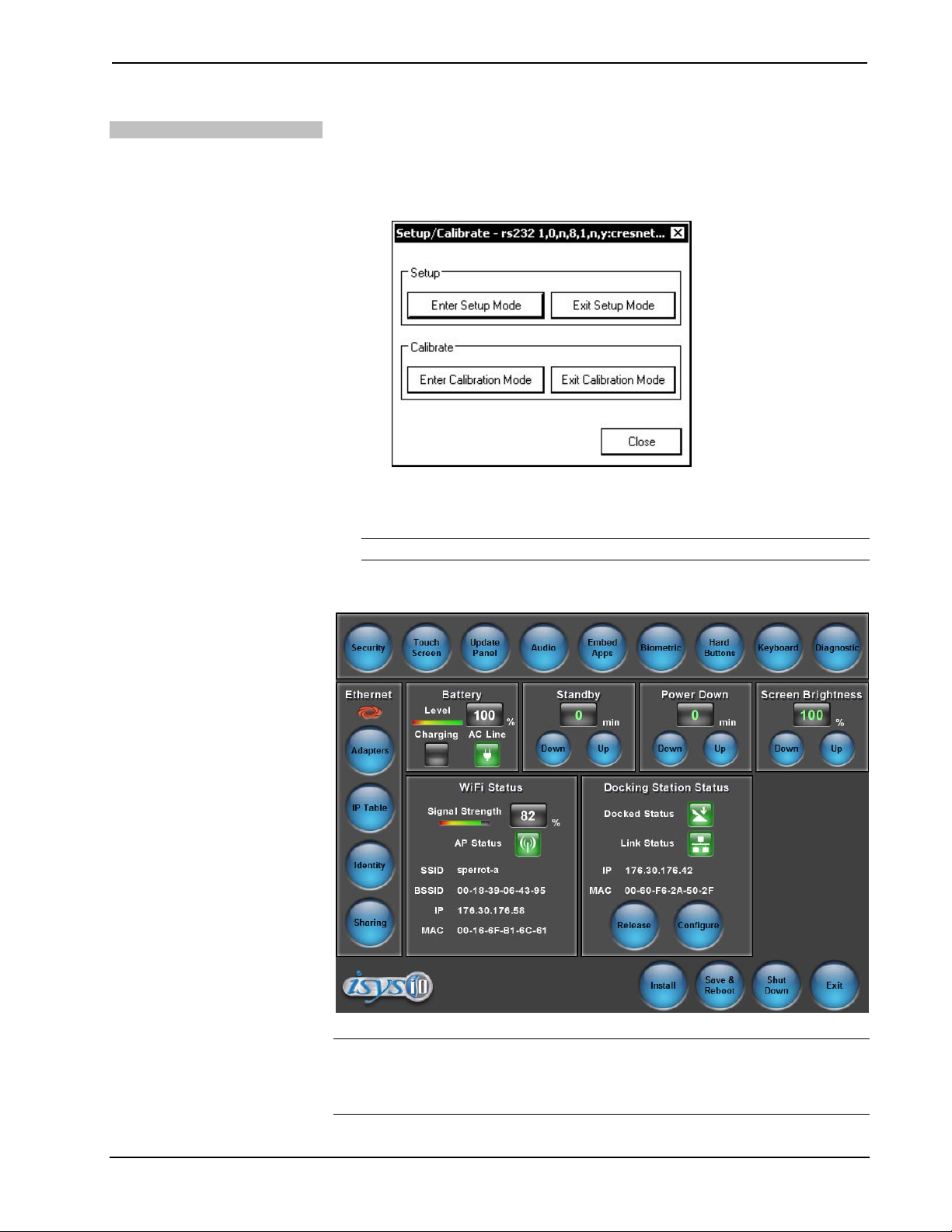
Via Crestron Toolbox
1. Establish communication with the touchpanel (refer to “Establishing
Communication” on page 61 for details).
2. Right-click on the device and select Functions | Setup Mode….
“Setup/Calibrate” Window
3. Select Enter Setup Mode. The setup menu will be displayed as shown in
the following diagram.
NOTE: Select Exit Setup Mode to exit the setup menu.
TPMC-8X Setup Menu
NOTE: Another way to enter the setup menu (after a project has been loaded) is to
touch the screen during boot up when you see the “Preparing to Load Project”
message. Maintain touch until after the countdown, when the message will change to
“Loading Setup Screen”.
Operations Guide – DOC. 6539B Isys i/O™ 8.4” WiFi Touchpanel: TPMC-8X • 13
Isys i/O™ 8.4” WiFi Touchpanel Crestron TPMC-8X
The setup menu provides access to all basic functions and parameters. It is divided
into Setup, Ethernet, Battery, Standby, Power Down, Screen Brightness, WiFi Status
and Docking Station Status sections. There are also buttons for Install, Save &
Reboot, Shut Down and Exit.
NOTE: To allow the touchpanel to upload projects, standby is disabled until
approximately five minutes after the project is loaded.
To exit the setup menu and return to the program, press Exit, located at the bottom
of the setup menu. To save any changes and reboot the touchpanel, press Save &
Reboot, located at the bottom of the setup menu. Use the Shut Down button to turn
off the touchpanel.
Setup Menu Details
The setup menu allows configuration of the touchpanel’s settings for security, touch
screen calibration, runtime project, audio, embedded applications, diagnostics and
hard button programming. The setup menu also has a button that will toggle the onscreen keyboard on and off.
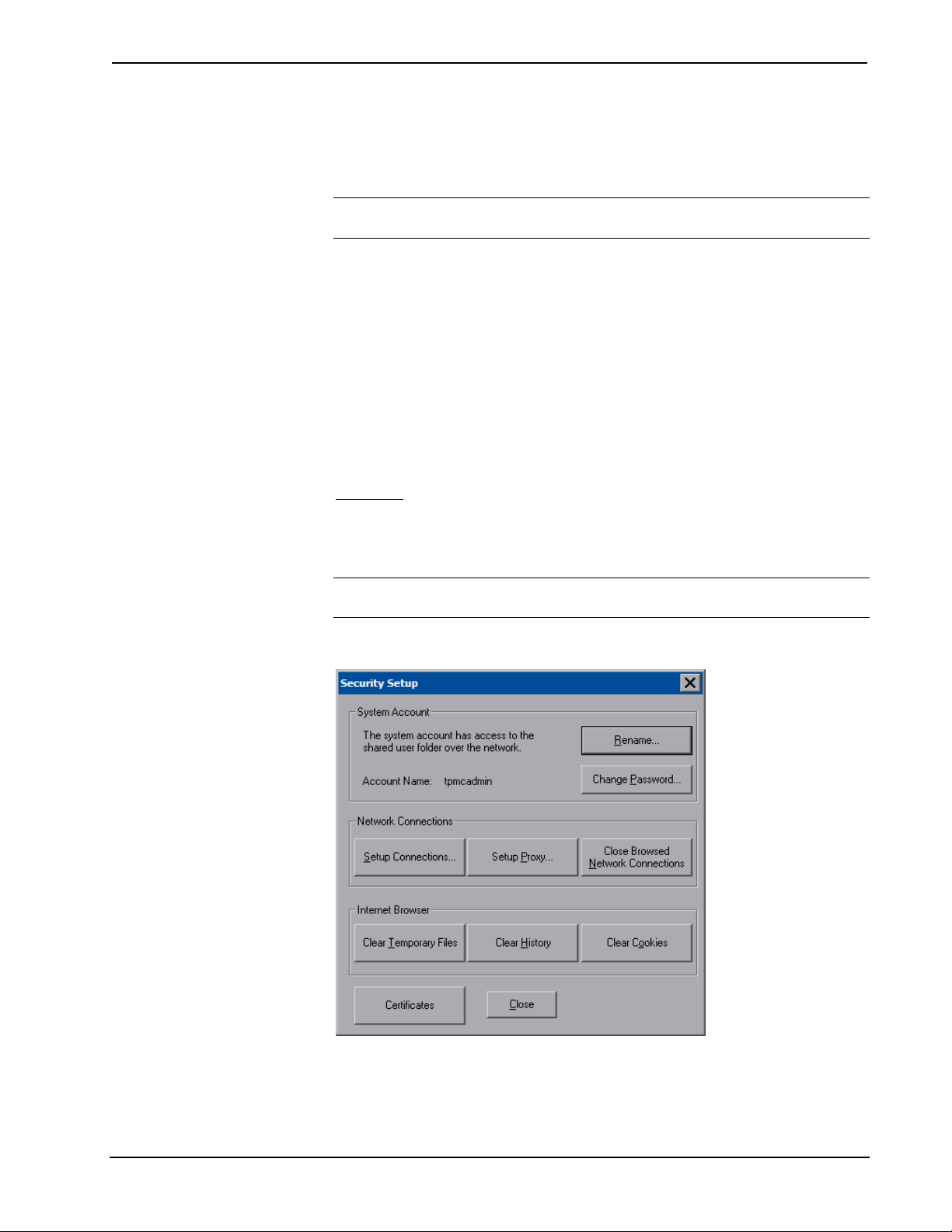
Security
The Security button opens the “Security Setup” window, which allows the user to
change the username and password of the system account, setup and close network
connections and clear cookies.
NOTE: To use the on-screen keyboard for security settings, press Keyboard on the
setup menu before pressing Security.
“Security Setup” Window
Click Setup Connections… to open the “Network Connections” window. This
window is used to map to a network drive. A mapped network drive permits easy
access to embedded application files (Word, Excel, PowerPoint, etc.) and provides a
14 • Isys i/O™ 8.4” WiFi Touchpanel: TPMC-8X Operations Guide – DOC. 6539B
Crestron TPMC-8X Isys i/O™ 8.4” WiFi Touchpanel
location to save files. To further customize the installation, network drives
containing compiled touchpanel project files can also be mapped.
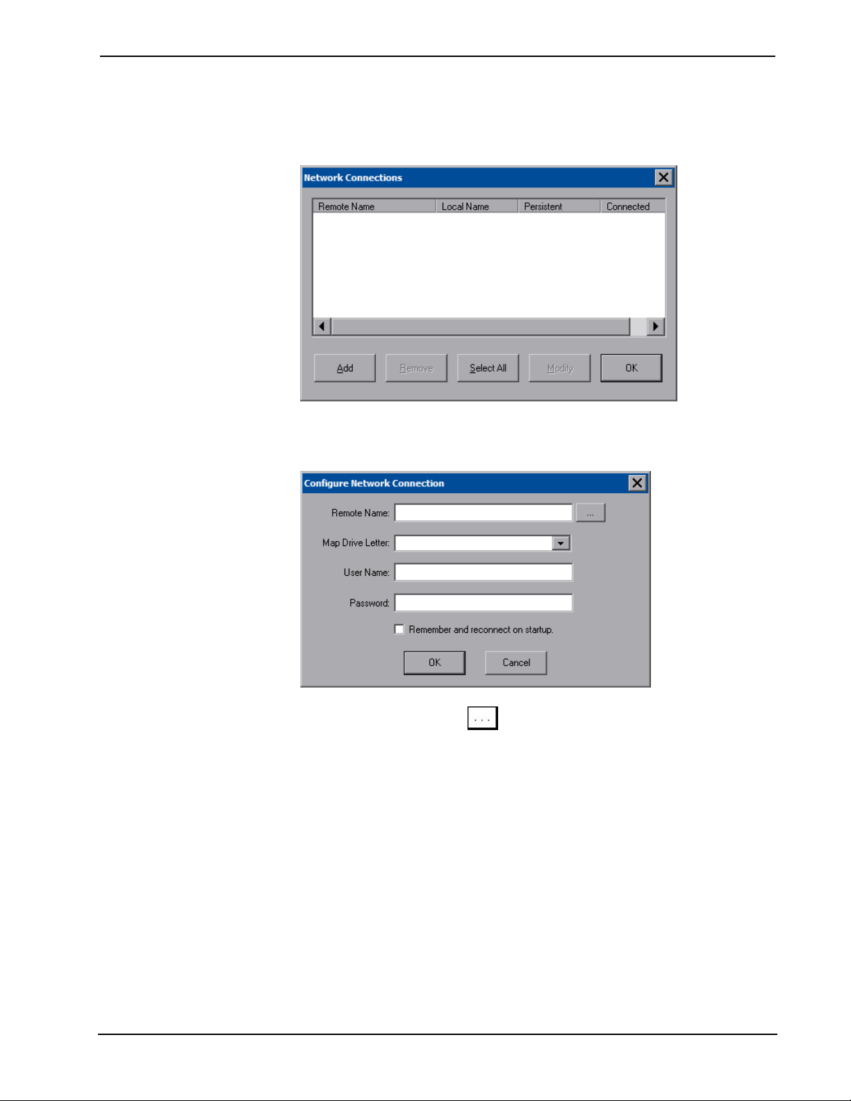
“Network Connections” Window
To add a new network connection, click Add.
“Configure Network Connection” Window
To add a network drive, click
1. Map this connection by selecting a drive letter from the Map Drive Letter
drop box.
2. Enter a User Name and Password.
3. Click the Remember and reconnect on startup checkbox if so desired.
4. Click OK to enable the new network connection and return to the “Network
Connections” window.
to browse for the new network connection.
Once all changes to network connections have been completed, click OK to return to
the “Security Setup” window.
The Certificates button can be used to install or uninstall certificates used for server
and/or user authentication when making a secure connection (for example, to a
secured wireless access point). In order to use certificates, the TPMC-8X Security
Pack must be installed (refer to “Appendix A: TPMC-8X Security Pack (Atheros)”
on page 69 or “Appendix B: TPMC-8X Security Pack (Intel PROSet)” on page 73
for details).
Operations Guide – DOC. 6539B Isys i/O™ 8.4” WiFi Touchpanel: TPMC-8X • 15

Isys i/O™ 8.4” WiFi Touchpanel Crestron TPMC-8X
Press Close to return to the setup menu.
Touch Screen
When Touch Screen is pressed, the calibration screen will be displayed. Touch the
screen to begin the calibration process. If the screen is not pressed within 10 seconds,
the calibration sequence will stop and the screen will again display the setup menu.
If the screen is touched within the 10-second timeout, it displays a series of messages
indicating that you should touch the red square in five places around the screen.
These messages will appear sequentially starting with “Touch the red square” at the
top of the screen toward the upper left corner. Touch and hold the center of the red
square to initiate calibration. The message will say “Hold…” for a few seconds, then
change to “Lift off to proceed”. Touch the displayed squares as prompted
everywhere they appear around the screen until the calibration is complete and you
are returned to the setup menu.
NOTE: When touching the screen during calibration, be as accurate as possible.
Use the tip of the included stylus. To cancel calibration and return to the setup menu
without saving calibration data, ignore the “Touch the red square” message. After
about 10 seconds, the setup menu will be displayed. If a USB keyboard is attached to
the touchpanel, you can also press the Escape key (Esc) to cancel calibration and
return to the setup menu.
NOTE: The touchpanel’s calibration routine can also be accessed through Crestron
Toolbox if the touchpanel is connected to a control system via TCP/IP. From the
System Info page, select Functions | Setup Mode…. Select Enter Calibration
Mode to begin calibration.
Update Panel
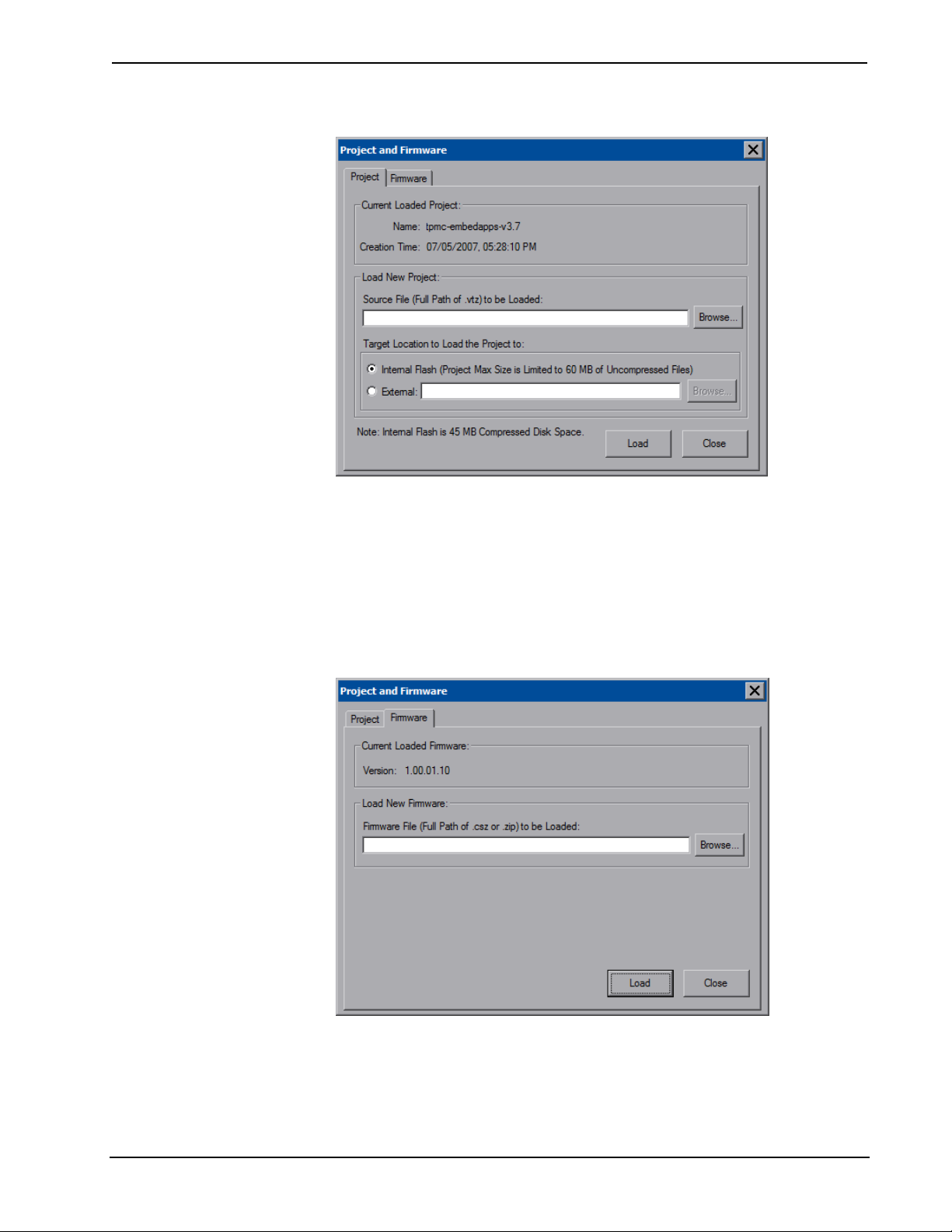
The Update Panel button permits the selection of the touchpanel program, a .vtz
file. The Project tab of the “Project and Firmware” window (refer to illustration on
the following page) displays the Current Loaded Project and also has a Load New
Project section.
Current Loaded Project displays the Name and Creation Time of the current project.
In the Load New Project section, press Browse and select the compiled project (i.e.
the .vtz file) to be loaded from a network drive, USB device or flash drive. You can
choose the location where your uncompressed project files will be stored. The
default file location is the internal flash. Press Load to uncompress the project file,
place it in the destination selected in Target Location to Load the Project to and
display it on the touchpanel.
NOTE: If there is a mapped network drive on the touchpanel, the first time you
select Browse, it may take some time for the “Open” window to appear.
NOTE: When selecting Browse, the contents of the “Recent” folder will not be
available.
NOTE: Projects can also be loaded via Crestron Toolbox.
NOTE: If External is checked, the display list cannot be viewed via Crestron
Toolbox.
16 • Isys i/O™ 8.4” WiFi Touchpanel: TPMC-8X Operations Guide – DOC. 6539B
Crestron TPMC-8X Isys i/O™ 8.4” WiFi Touchpanel
“Project and Firmware” Window (Project Tab)
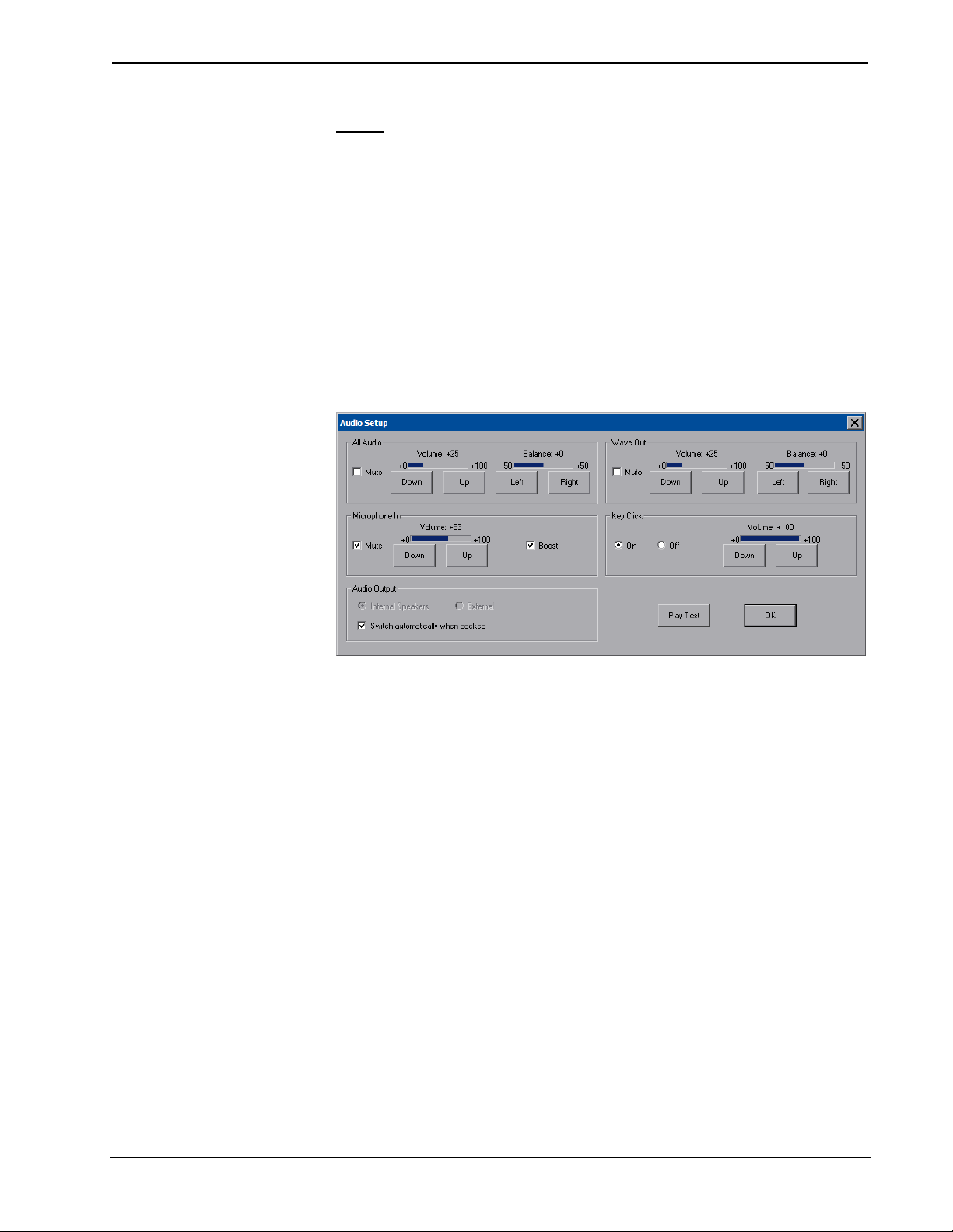
The Firmware tab of the “Project and Firmware” window (refer to illustration
below) displays the Current Loaded Firmware and also has a Load New Firmware
section.
Current Loaded Firmware displays the Version of the current firmware.
In the Load New Firmware section, press Browse and select the firmware file (i.e.
the .csz or .zip file) to be loaded from a network drive, USB device or flash drive.
Press Load to load the new firmware.
“Project and Firmware” Window (Firmware Tab)
Operations Guide – DOC. 6539B Isys i/O™ 8.4” WiFi Touchpanel: TPMC-8X • 17
Isys i/O™ 8.4” WiFi Touchpanel Crestron TPMC-8X
Audio
The Audio button opens the “Audio Setup” window. Overall All Audio volume and
balance controls and a Mute checkbox are available as well as volume and balance
controls and Mute checkboxes for Wave Out and Microphone In. The Microphone In
settings also include a Boost checkbox, which applies a 20 dB boost to the level of
the microphone input. The key click sound can be enabled or disabled with the Key
Click On and Off radio buttons.
When connected to the (optional) TPMC-8X-DSW docking station, the Audio
Output section of the window provides radio buttons for selection of internal or
external speakers. In addition, a checkbox allows for automatic switching to external
speakers when docked.
Pressing Play Test plays a short internal audio file. Changes to audio settings are
made in real time.
“Audio Setup” Window
18 • Isys i/O™ 8.4” WiFi Touchpanel: TPMC-8X Operations Guide – DOC. 6539B
Crestron TPMC-8X Isys i/O™ 8.4” WiFi Touchpanel
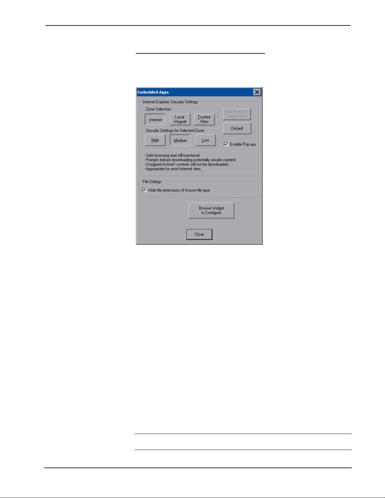
Embed Apps (Embedded Applications)
The Embed Apps button opens a window that permits you to set internet security to
different levels for different types of internet sites.
“Embedded Apps” Window
Three security levels (High, Medium and Low) can be selected for each of the three
zones (Internet, Local Intranet, and Trusted Sites). The security levels are defined
as:
• High: The safest way to browse, but also the least functional. Less secure
features are disabled. Appropriate for sites that may have harmful content.
• Medium: Safe browsing and still functional. Prompts before downloading
potentially unsafe content. Unsigned ActiveX controls will not be
downloaded. Appropriate for most internet sites.
• Low: Minimal safeguards and warning prompts are provided. Most content
is downloaded and run without prompts. All active content can run.
Appropriate for sites you absolutely trust.
Press Default to restore the default security settings. By default, security is set to
Medium for Internet and Local Intranet, and Low for Trusted Sites.
The “Embedded Apps” window also permits you to enable the popup windows
(child windows) that open when you are in Internet Explorer (not the popup windows
of the embedded applications).
The Browse Widget to Configure button opens a window that gives you access to
the widgets you have installed. Right clicking a widget allows you to set its
properties, such as the city for the weather report, the default URL for a webcam or
the stocks you would like to see on the stock ticker. Other widget properties such as
position and translucence are set with VisionTools Pro-e.
NOTE: If there is a mapped network drive on the touchpanel, the first time you
select Browse, it may take some time for the “Open” window to appear.
Operations Guide – DOC. 6539B Isys i/O™ 8.4” WiFi Touchpanel: TPMC-8X • 19
Isys i/O™ 8.4” WiFi Touchpanel Crestron TPMC-8X
The currently supported version of the Yahoo Widget Engine is 2006.06.16.01. The
currently supported version of Skype is 2.0.0.107.
NOTE: Refer to the Crestron website (www.crestron.com
4190, for information on the latest versions of the software.
Some applications (for example Skype) will sometimes display a pop up window
asking if you would like to obtain a newer version. Before installing a newer version,
the old version must first be uninstalled. The newer version can then be installed
using the regular install process. (Refer to “Install Details” on page 46 for details.)
Press Close after all changes have been made. The touchpanel must be rebooted for
changes to take effect. Refer to “Save & Reboot and Shut Down Details” on page 50
for more information.
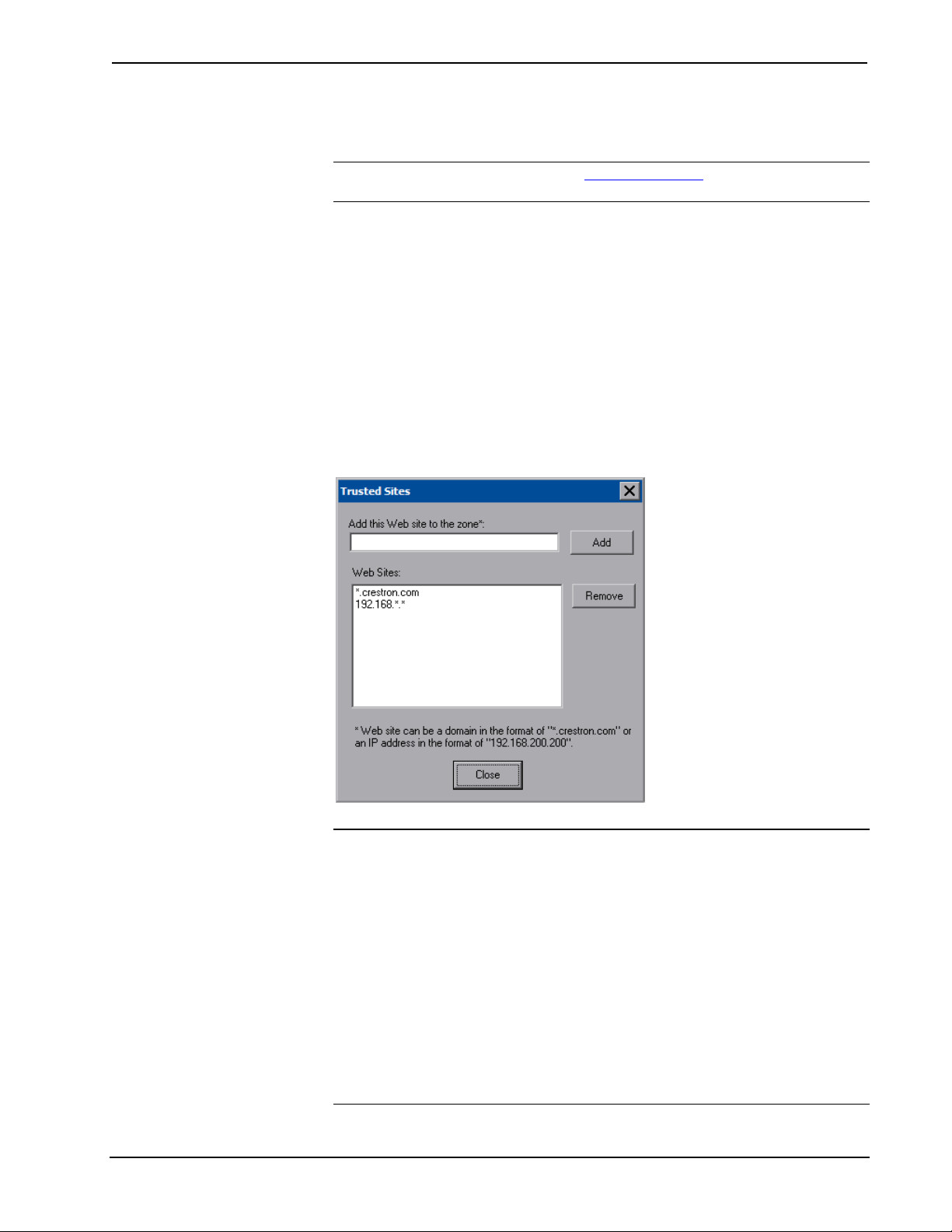
A list of trusted sites can be created and edited by pressing Add/Remove Trusted
Sites. Pressing this button will open the “Trusted Sites” window. From here, trusted
sites can be added and edited. Sites are listed by domain name or IP address. Once
all sites have been entered, press Close.
“Trusted Sites” Window
), online help Answer ID
NOTE: Save & Reboot on the setup menu must be selected for Embedded Apps
changes to take effect.
NOTE: While browsing the Internet with the TPMC-8X, clicking on a link may
cause a message box titled "Restrictions" to appear that contains the text "This
operation has been cancelled due to restrictions in effect on this computer. Please
contact your system administrator." If this message appears, checking Enable Popup
Windows in the “Embedded Apps” window may correct this error. Other restrictions
may also cause this error, so this may not prevent all occurrences.
NOTE: The TPMC-8X Multi-Language Pack allows the user to view documents
written in any of 32 supported international languages by all the embedded apps in
the touchpanel. For details, refer to “Appendix C: TPMC-8X Multi-Language Pack”
on page 78.
20 • Isys i/O™ 8.4” WiFi Touchpanel: TPMC-8X Operations Guide – DOC. 6539B

Crestron TPMC-8X Isys i/O™ 8.4” WiFi Touchpanel
NOTE: The TPMC-8X supports automatic connection to the VNC server when the
VNC View application is opened. For automatic connection without having to enter
the server location and password every time the VNC viewer is opened, launch the
application and using a USB mouse, right-click on the VNC viewer window, then
select Save configuration info as….
NOTE: Refer to the Crestron website (www.crestron.com
4627, for information on how to set up the VNC viewer. Refer to Answer ID 3345
for information on how to program the MJPEG viewer.
NOTE: Applications that use audio will need to be re-launched when the TPMC-8X
is docked or undocked from the (optional) TPMC-8X-DSW docking station, unless it
is set to use Internal Speakers and Switch automatically when docked is unchecked
(refer to “Audio” which starts on page 18 for details).
), online help Answer ID
Biometric
The built in fingerprint scanner makes user identification easy. Up to 10 fingers can
be scanned for each user. Each finger scan is able to trigger a join and/or an
automated action (such as entering setup mode, wake, sleep, etc.).
Pressing Biometric will display the “Biometric Configuration Properties” window.
New users can be enrolled from here and the resulting join and/or action for each
finger can be edited. The Enabled button at the bottom of the window can be used to
turn the fingerprint scanner on and off.
“Biometric Configuration Properties” Window (Users)
Operations Guide – DOC. 6539B Isys i/O™ 8.4” WiFi Touchpanel: TPMC-8X • 21
Isys i/O™ 8.4” WiFi Touchpanel Crestron TPMC-8X
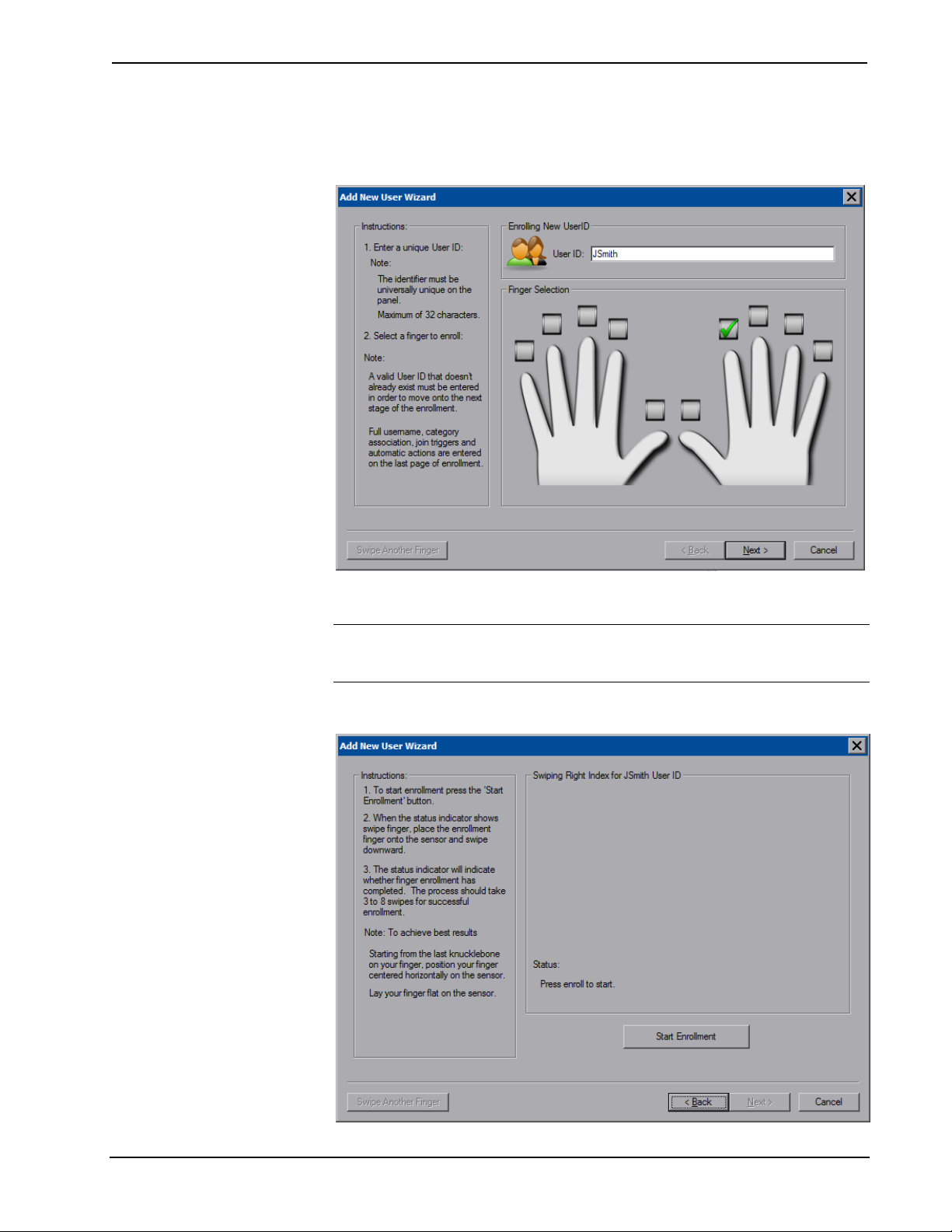
From the Users tab, press Add (in the upper half of the window) to start the “Add
New User Wizard”.
“Add New User Wizard” First Window
After entering a User ID and selecting which finger to scan, press Next.
NOTE: A valid User ID that does not already exist must be entered in order to
move onto the next stage of enrollment. Only one User ID should be used per
person.
“Add New User Wizard” Second Window
22 • Isys i/O™ 8.4” WiFi Touchpanel: TPMC-8X Operations Guide – DOC. 6539B

Crestron TPMC-8X Isys i/O™ 8.4” WiFi Touchpanel
At the next window, press Start Enrollment.
You will be instructed to swipe or slide the selected finger over the sensor.
“Add New User Wizard” Window - Ready For Swipe
You will need to swipe or slide the selected finger over the sensor a few times and
will see a count for how many swipes have occurred. For each swipe, you will see
the scanned fingerprint.
“Add New User Wizard” Window - Showing Scanned Fingerprint
Operations Guide – DOC. 6539B Isys i/O™ 8.4” WiFi Touchpanel: TPMC-8X • 23

Isys i/O™ 8.4” WiFi Touchpanel Crestron TPMC-8X
When scanning is complete you will see an “Enrollment Complete”. Press Next to
proceed.
“Add New User Wizard” Window - Showing “Enrollment Complete” Message
The next window allows you to enter a user name, set a category (i.e. a user defined
grouping such as “admin” or “guest”, etc.), join number and/or an automated action
to associate with the finger scan. These can also be set later in the “Biometric
Management” window.
“Add New User Wizard” Window - Showing Options After Scanning
24 • Isys i/O™ 8.4” WiFi Touchpanel: TPMC-8X Operations Guide – DOC. 6539B

Crestron TPMC-8X Isys i/O™ 8.4” WiFi Touchpanel
To scan another finger, press Swipe Another Finger. When done, press Finish to
return to the “Biometric Configuration Properties” window.
“Biometric Configuration Properties” Window - Showing New User ID and Scan Data
If more than one finger is to be enrolled, press Add (in the lower half of the
window). Press OK to return to the setup menu or press Edit (in the lower half of the
window) to access the “User Biometric Information” window.
“User Biometric Information” Window
You can also press Test to open the “Biometric Information” window, to practice
finger swipes and verify identities. (Refer to illustration on the following page.)
Operations Guide – DOC. 6539B Isys i/O™ 8.4” WiFi Touchpanel: TPMC-8X • 25

Isys i/O™ 8.4” WiFi Touchpanel Crestron TPMC-8X
“Biometric Information” Window
If the finger swipe matches one in the touchpanel’s database, it will show an
“Identification Match Found” message along with the matching Unique ID, Name
and Finger.
“Biometric Information” Window - Showing Match Found
If the finger swipe does not match one in the touchpanel’s database, it will show an
“Identification No Match Found” message.
26 • Isys i/O™ 8.4” WiFi Touchpanel: TPMC-8X Operations Guide – DOC. 6539B

Crestron TPMC-8X Isys i/O™ 8.4” WiFi Touchpanel
“Biometric Information” Window - Showing No Match Found
If the touchpanel is unable to read the finger swipe, it will show a message indicating
the type of error. In the example below, it shows the “Swipe Too Short” message.
“Biometric Information” Window - Showing Swipe Error
Press OK at any time to return to the “Biometric Configuration Properties” window.
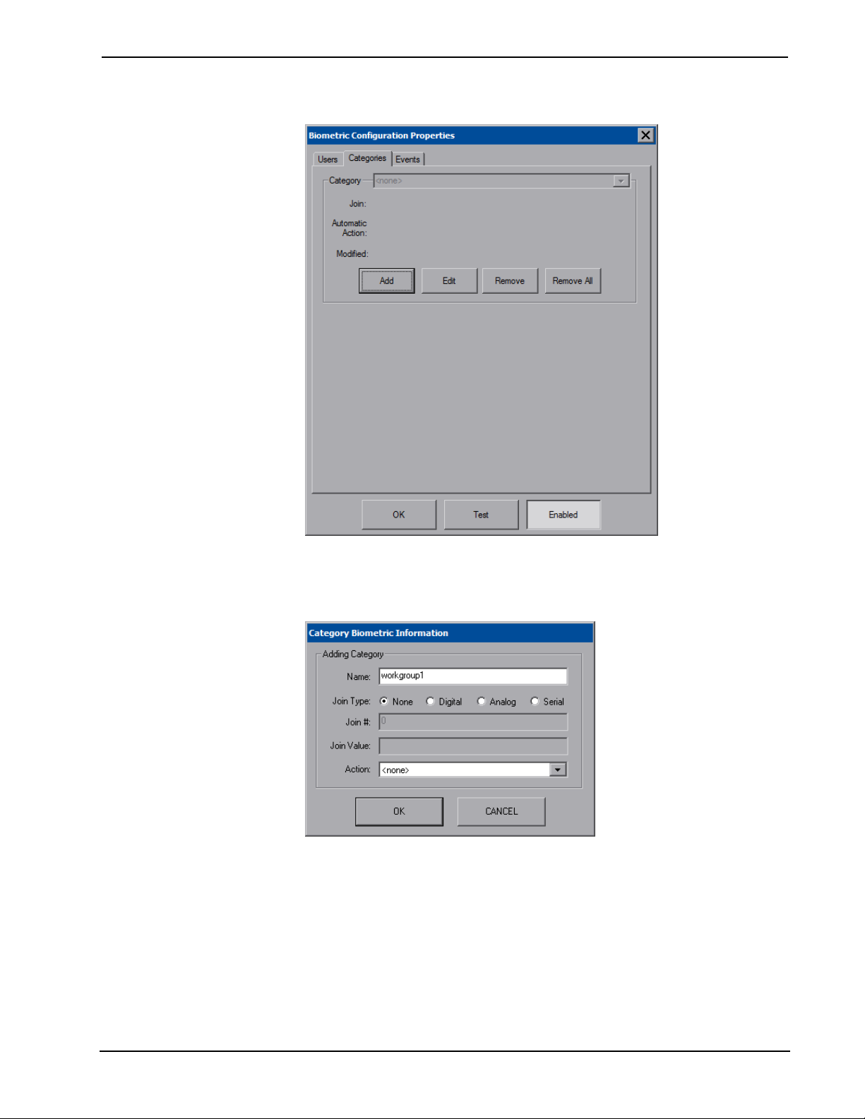
From the Categories tab of the “Biometric Configuration Properties” window, you
can add, edit or remove categories.
Operations Guide – DOC. 6539B Isys i/O™ 8.4” WiFi Touchpanel: TPMC-8X • 27
Isys i/O™ 8.4” WiFi Touchpanel Crestron TPMC-8X
“Biometric Configuration Properties” Window (Categories)
To create a new category, press Add to open the “Category Biometric Information”
window.
“Category Biometric Information” Window
Press OK to accept (or press CANCEL to cancel) and return to the “Biometric
Configuration Properties” window.
From the Events tab of the “Biometric Configuration Properties” window, you can
add, edit or remove events.
28 • Isys i/O™ 8.4” WiFi Touchpanel: TPMC-8X Operations Guide – DOC. 6539B

Crestron TPMC-8X Isys i/O™ 8.4” WiFi Touchpanel
“Biometric Configuration Properties” Window (Events)
Pressing the down arrow will open a drop down list of events.
“Biometric Configuration Properties” Window - Showing Event List (Events)
Operations Guide – DOC. 6539B Isys i/O™ 8.4” WiFi Touchpanel: TPMC-8X • 29
Isys i/O™ 8.4” WiFi Touchpanel Crestron TPMC-8X
The following are the events that can be selected:
1. Error: An error occurred while trying to identify the swiped finger. It
could be any of the events listed below from #6 through #13.
2. Finger detected: A finger has been detected and identification will start.
3. Identifying: The sensor is in the process of identifying.
4. Match: Identification has completed and a match has been found.
5. No-match: Identification has completed and no match was found in the
user database.
6. Surface dirty: The surface is too dirty for identification.
7. Swipe too far left
8. Swipe too far right
9. Swipe too fast
10. Swipe too little pressure
11. Swipe too short
12. Swipe too skewed
13. Swipe too slow
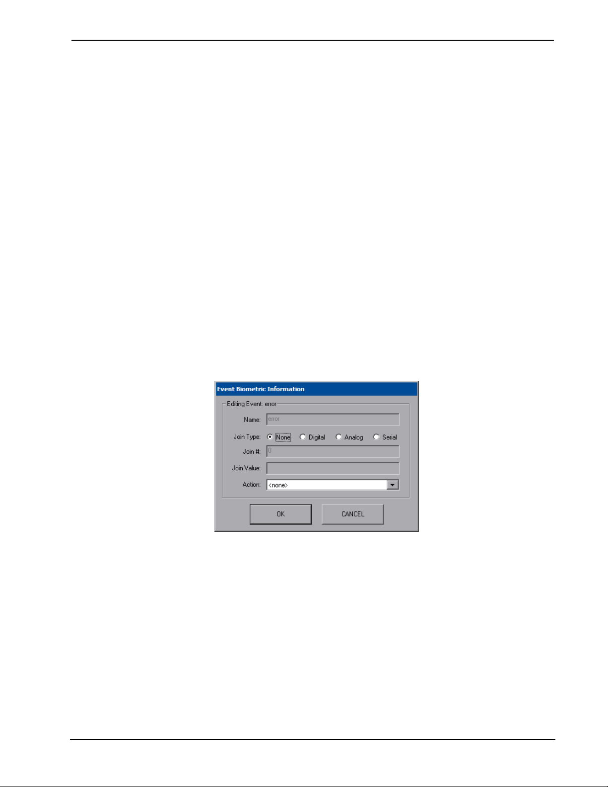
Select the event you wish to edit and press Edit to open the “Event Biometric
Information” window.
“Event Biometric Information” Window
Press OK to accept (or press CANCEL to cancel) and return to the “Biometric
Configuration Properties” window. Then press OK to return to the startup menu.
In actual use, a popup window will appear showing if a match was found, if a match
was not found or if the scan was no good (for example, too short). The appearance of
the Biometric popup window can be configured using the Configure Messages
button (refer to “Diagnostic” which starts on page 33 for details).
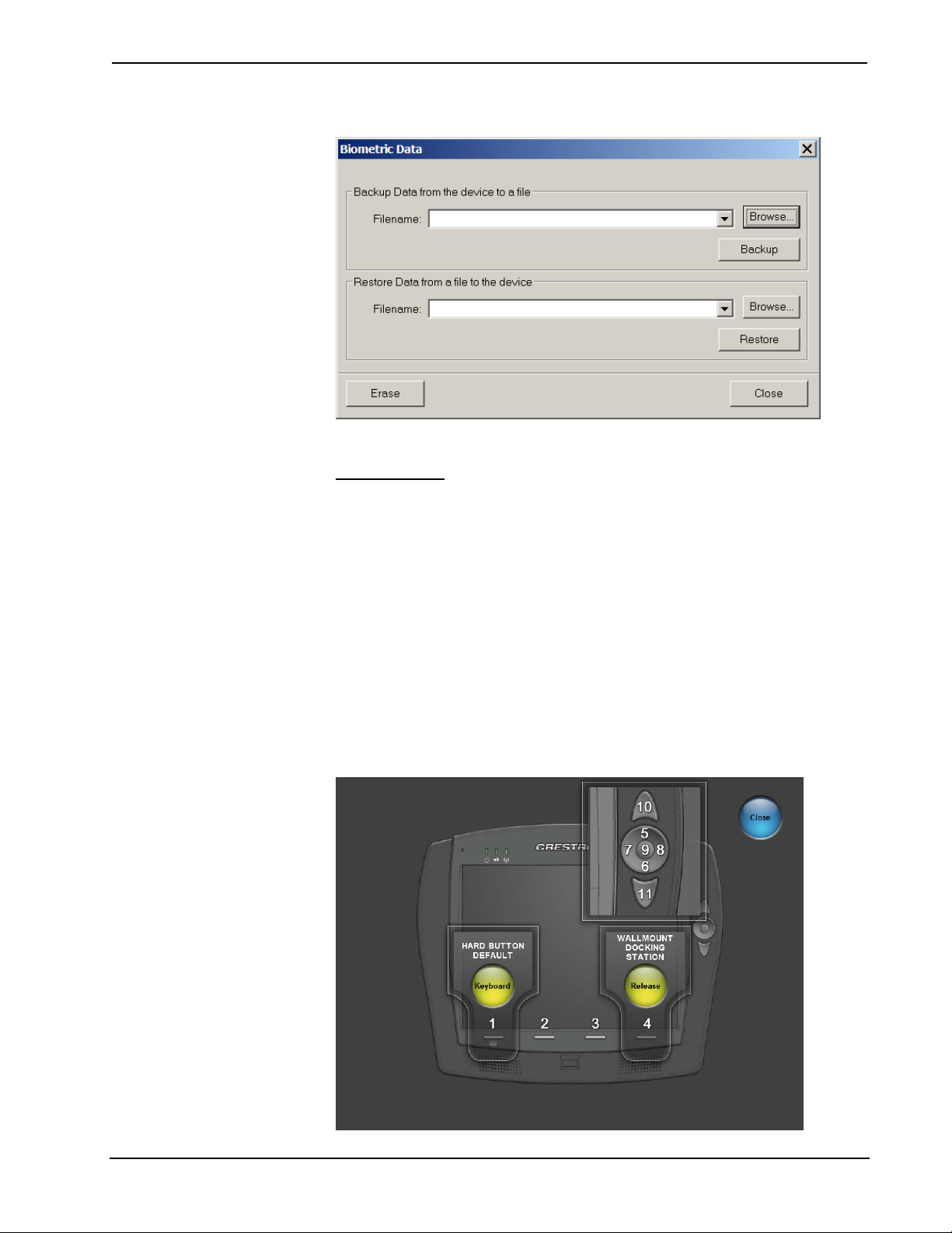
Crestron Toolbox includes a utility that will allow the database from one TPMC-8X
to be shared with another, by backing up the database from one touchpanel and
restoring it to another. From the Functions menu in Toolbox, select “Biometric
Data…” to open the utility, as shown in the illustration on the following page.
30 • Isys i/O™ 8.4” WiFi Touchpanel: TPMC-8X Operations Guide – DOC. 6539B
Crestron TPMC-8X Isys i/O™ 8.4” WiFi Touchpanel
“Biometric Data” window in Toolbox
Hard Buttons
Pressing Hard Buttons will display a screen that provides visual feedback for all
button presses. Pressing softkeys 2 through 4, the up or down buttons or any of the
buttons on the 5-way thumbpad will result in its corresponding number on the screen
illuminating in yellow.
By default, softkey number 1 toggles the on-screen keyboard on and off. However,
this can be disabled using the Keyboard button on the Hard Buttons screen.
Softkey number 1 can then be used like any of the other buttons. If disabled, it will
use the VisionTools
®
Pro-e (VT Pro-e) project assignment.
By default, softkey number 4 will release the touchpanel from the (optional)
TPMC-8X-DSW docking station.
Buttons are programmed using VT Pro-e.
Press Close to return to the setup menu.
“Hard Buttons” Window
Operations Guide – DOC. 6539B Isys i/O™ 8.4” WiFi Touchpanel: TPMC-8X • 31
Isys i/O™ 8.4” WiFi Touchpanel Crestron TPMC-8X
Keyboard
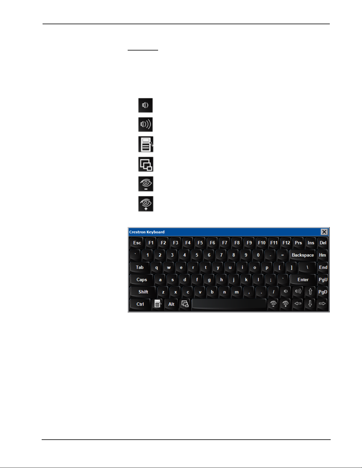
Click the Keyboard button to display the on-screen keyboard.
The on-screen keyboard can be used in an identical manner to a physically connected
keyboard. It can be used in any of the embedded applications, for example, to enter a
web address or to enter data into a spreadsheet, etc.
The on-screen keyboard also has a few special keys:
Volume down
Volume up
Right click: simulates right-click of mouse
Size: toggles on-screen keyboard size (small, medium, large)
Keyboard translucence down: decreases keyboard translucence
Keyboard translucence up: increases keyboard translucence
On-Screen Keyboard
The initial position of the on-screen keyboard is determined by the VisionTools
Pro-e program or SIMPL Windows settings. The on-screen keyboard will default to
its largest size.
In use, when the on-screen keyboard is moved and/or resized and then closed, it will
re-open in the same position it was in and at the same size it was when closed. This
position and size will remain in memory until the touchpanel is re-booted or it is reset by the SIMPL Windows program. After reboot, the position of the on-screen
keyboard will revert to the defaults set in the VisionTools Pro-e or SIMPL Windows
program. The size will revert to the largest as determined by the firmware installed in
the touchpanel.
®
Exit the on-screen keyboard by selecting File | Exit or by pressing the “X” close
button in the upper right corner of the keyboard window. If softkey number 1 has the
keyboard enabled, you can also exit the keyboard by using softkey number 1, a
reserve join number in VT Pro-e or a device extender in SIMPL Windows.
32 • Isys i/O™ 8.4” WiFi Touchpanel: TPMC-8X Operations Guide – DOC. 6539B
Crestron TPMC-8X Isys i/O™ 8.4” WiFi Touchpanel
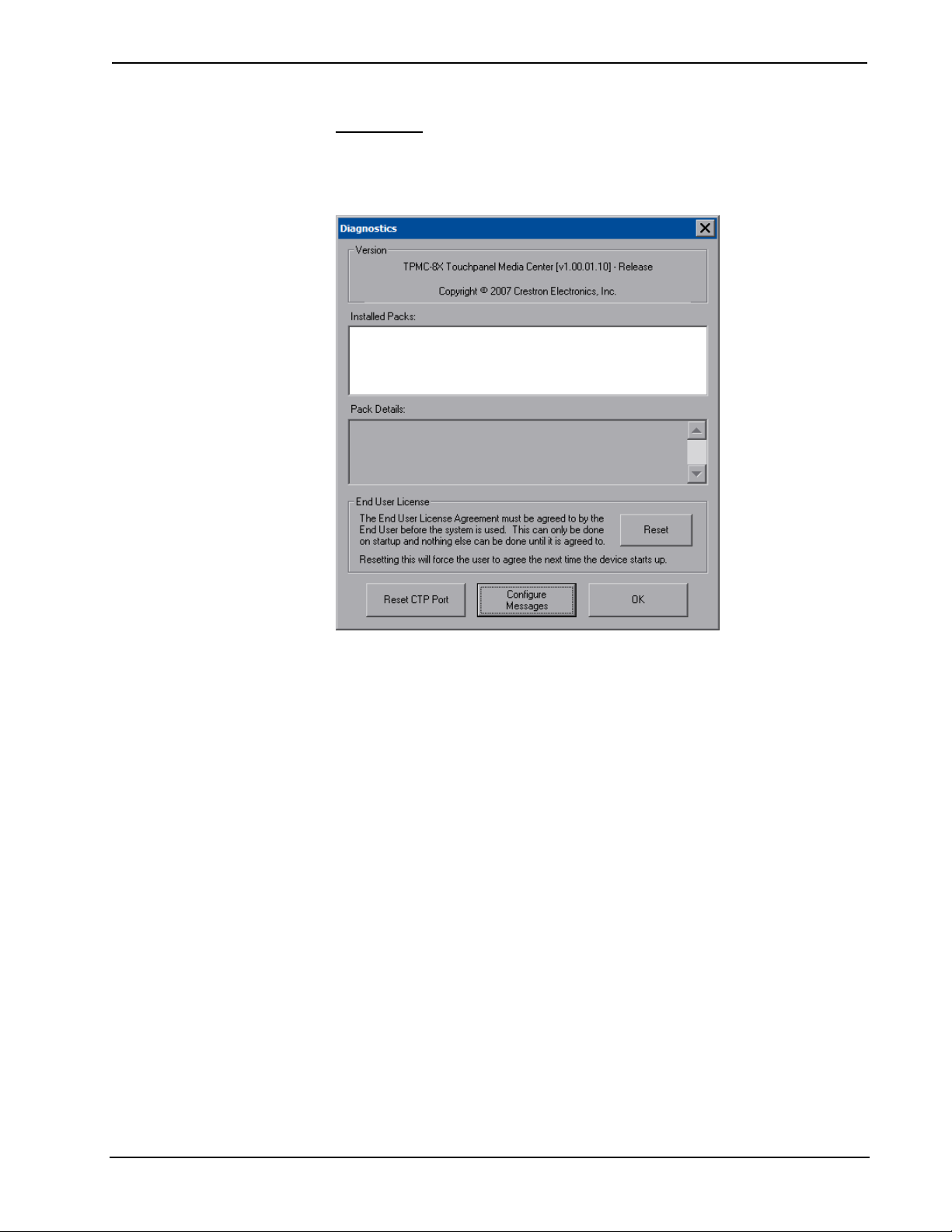
Diagnostic
Press the Diagnostic button to display the firmware version number, see Installed
Packs and to reset the end user license from the “Diagnostics” window.
“Diagnostics” Window
Reset CTP Port resets the default value of the CTP port to 41795, for terminal
connection using Crestron Toolbox.
To configure the appearance of popup messages, biometric messages and passcode
messages, press Configure Messages. The “Message Configurations Properties”
window will open.
Operations Guide – DOC. 6539B Isys i/O™ 8.4” WiFi Touchpanel: TPMC-8X • 33

Isys i/O™ 8.4” WiFi Touchpanel Crestron TPMC-8X
“Message Configurations Properties” Window (Popup Messages Tab)
To configure the appearance of popup messages, click on the Popup Messages tab.
There are various types of popup messages. The button associated with each type
(Network, Warning, Error and Fatal) allows you to set which types are displayed.
Following are definitions of each message type:
• Network: A network event has occurred that may effect the normal
operation of the unit.
• Warning: An event occurred that may effect the normal operation of the
unit.
• Error: An operation has failed.
• Fatal: An event occurred which will require the unit to be reset.
The Colors controls allow you to determine background and text color of popup
messages. Also provided are controls for popup message Timeout and Translucence.
The Default button restores the original Colors, Timeout and Translucence settings,
as well as enabling display of Network and Fatal messages. A Test Message button
lets you see the changes to popup message appearance and timing. Press Close to
close the test popup window.
NOTE: The default values for Color are white for Upper Left, blue for Lower-Right
and black for Text. The default values for Timeout and Translucence are 0 and 90
respectively.
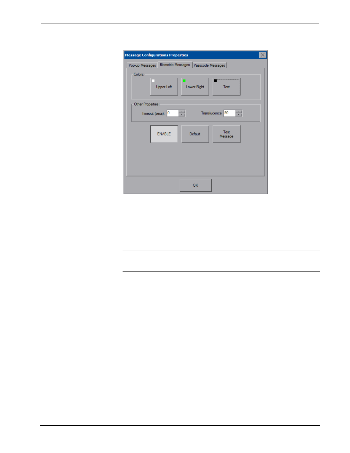
To configure the appearance of biometric messages, click on the Biometric Messages
tab.
34 • Isys i/O™ 8.4” WiFi Touchpanel: TPMC-8X Operations Guide – DOC. 6539B
Crestron TPMC-8X Isys i/O™ 8.4” WiFi Touchpanel
“Message Configurations Properties” Window (Biometric Messages Tab)
The Colors controls allow you to determine background and text color of biometric
messages. Also provided are controls for popup message Timeout and Translucence.
The ENABLE button can be used to toggle biometric messages on and off. The
Default button restores the original Colors, Timeout and Translucence settings and
enables biometric messages. A Test Message button lets you see the changes to
biometric message appearance. Press Close to close the test popup window.
NOTE: The default values for Color are white for Upper Left, blue for Lower-Right
and black for Text. The default values for Timeout and Translucence are 0 and 90
respectively.
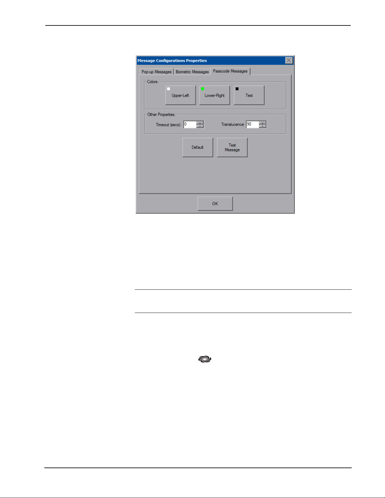
To configure the appearance of passcode messages, click on the Passcode Messages
tab.
Operations Guide – DOC. 6539B Isys i/O™ 8.4” WiFi Touchpanel: TPMC-8X • 35
Isys i/O™ 8.4” WiFi Touchpanel Crestron TPMC-8X
“Message Configurations Properties” Window (Passcode Messages Tab)
The Colors controls allow you to determine background and text color of passcode
messages, which will appear when releasing the touchpanel from the (optional)
TPMC-8X-DSW docking station (refer to “Docking Station Status Details” on page
45 for details). Also provided are controls for popup message Timeout and
Translucence.
The Default button restores the original Colors, Timeout and Translucence settings
and enables passcode messages. A Test Message button lets you see the changes to
passcode message appearance. Press Close to close the test popup window.
NOTE: The default values for Color are white for Upper Left, blue for Lower-Right
and black for Text. The default values for Timeout and Translucence are 0 and 90
respectively.
Ethernet Details
The Ethernet portion of the setup menu allows configuration of the touchpanel
settings for Ethernet communications.
The Crestron Swirl logo
illuminates to indicate the status of your connection to the control system(s):
• Green Connected
• Yellow Network trouble
at the top of the Ethernet portion of the setup menu
• Orange Connected to some but not all of the control systems (listed in IP
table)
• Red Not connected to any control system (listed in the IP table)
36 • Isys i/O™ 8.4” WiFi Touchpanel: TPMC-8X Operations Guide – DOC. 6539B
Crestron TPMC-8X Isys i/O™ 8.4” WiFi Touchpanel
Adapters
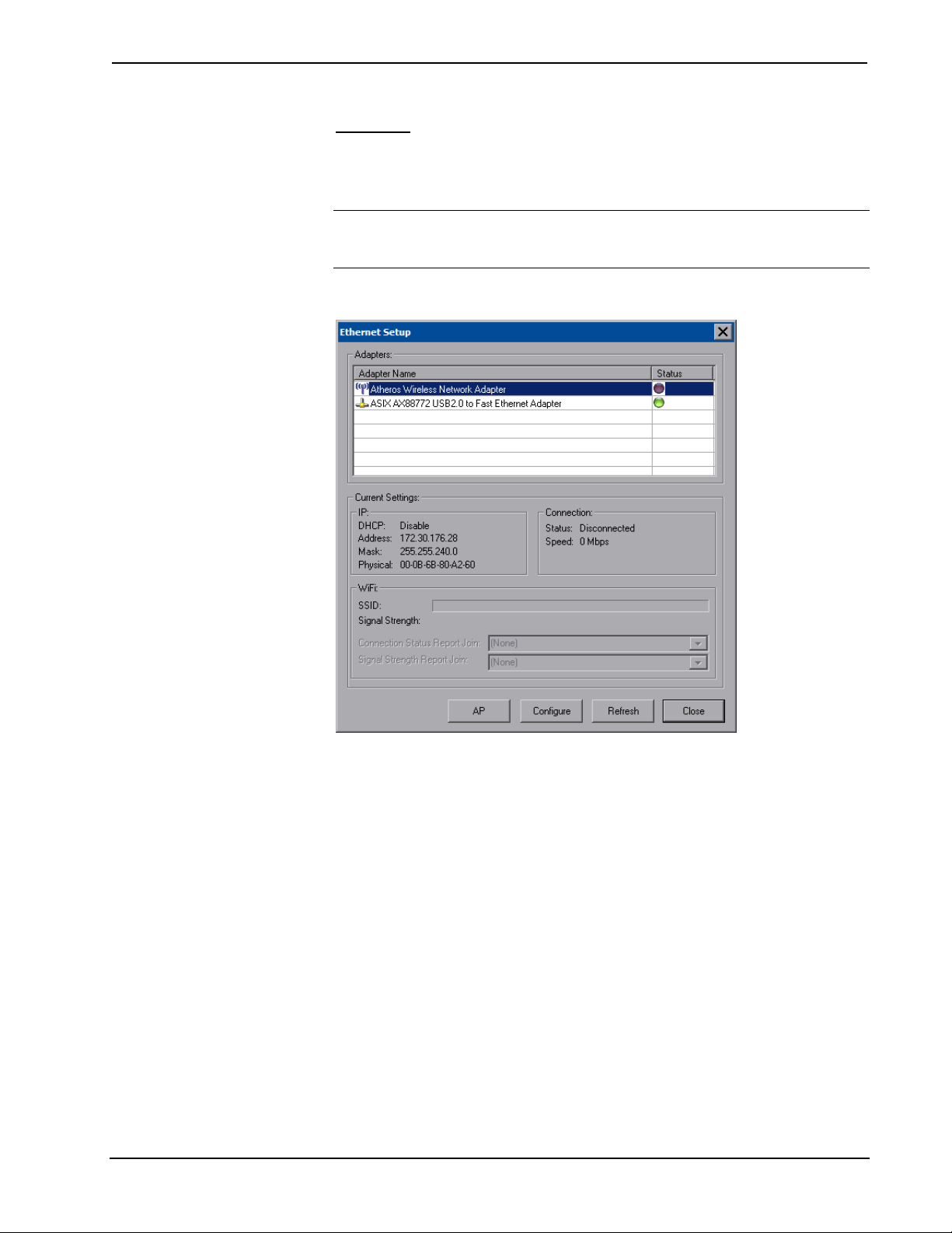
Press the Adapters button to access the “Ethernet Setup” window. To save any
changes, use the Save & Reboot button on the setup menu. The Ethernet address and
mask are displayed on this screen.
NOTE: The adapter listed in the “Ethernet Setup” window will depend on which
adapter came with your TPMC-8X. Either an Atheros or Intel PRO will be displayed,
as shown in the illustration below and the one on the following page.
“Ethernet Setup” Window (Atheros)
Operations Guide – DOC. 6539B Isys i/O™ 8.4” WiFi Touchpanel: TPMC-8X • 37

Isys i/O™ 8.4” WiFi Touchpanel Crestron TPMC-8X
“Ethernet Setup” Window (Intel PRO)
NOTE: The “ASIX AX88772 USB 2.0 to Fast Ethernet Adapter” line in the
“Ethernet Setup” window is seen only when the TPMC-8X is mounted on the
optional (TPMC-8X-DS) Docking Station/Charger.
NOTE: When the TPMC-8X is mounted on the optional Docking Station/Charger
and the wired LAN connection is used, the touchpanel auto-switches to wired
Ethernet communications. When the TPMC-8X is removed from the Docking
Station/Charger, it will seamlessly switch over to WiFi. Docking Station/Charger
must be using AC power pack for its LAN and USB ports to function.
NOTE: Refer to the Crestron website (www.crestron.com
4628, for information on how Windows switches between wired Ethernet
communications and WiFi.
NOTE: The TPMC-8X Security Pack allows the user to provide a username and
password for authentication in infrastructures utilizing a RADIUS (Remote
Authentication Dial In User Service) server. For details, refer to “Appendix A:
TPMC-8X Security Pack (Atheros)” on page 69 or “Appendix B: TPMC-8X
Security Pack (Intel PROSet)” on page 73.
Click Configure to open the “Wireless Network Connection Properties” window.
This window displays the connection and related required items.
), online help Answer ID
NOTE: When configuring an adapter, only one item can be modified at a time. For
example, to modify an IP address and also the wireless network, press Configure
and modify the IP address, then press OK (you must return to the “Ethernet Setup”
window). Press Configure again, modify the wireless network, then press OK. The
order in which modifications are performed does not matter.
38 • Isys i/O™ 8.4” WiFi Touchpanel: TPMC-8X Operations Guide – DOC. 6539B

Crestron TPMC-8X Isys i/O™ 8.4” WiFi Touchpanel
“Wireless Network Connection Properties” Window (General)
Click on the Wireless Networks tab.
“Wireless Network Connection Properties” Window (Wireless Networks)
NOTE: The link at the bottom of the window which says “Learn about setting up a
wireless network configuration” is not supported at this time.
From here you can add or remove wireless access points (WAPs) or routers. To view
wireless networks being accessed or scan for access points, click View Wireless
Networks to view the “Wireless Network Connection” window.
Operations Guide – DOC. 6539B Isys i/O™ 8.4” WiFi Touchpanel: TPMC-8X • 39

Isys i/O™ 8.4” WiFi Touchpanel Crestron TPMC-8X
“Wireless Network Connection” Window
Click Refresh network list to scan for available access points.
The TPMC-8X is already configured for DHCP. To establish static processing or to
switch between DHCP and static IP, use the General tab of the “Wireless Network
Connection Properties” window (refer to illustration on page 39), select Internet
Protocol (TCP/IP) and click Properties.
Click Set up a wireless network for a home or small office to start the Wireless
Network Setup Wizard.
The Wireless Network Setup Wizard will create a network with the Network
Authentication value set to Open. If your Wireless Access Point is configured with a
value other than Open, you must set this value manually, using the Wireless
Networks tab of the “Wireless Network Connection Properties” window (refer to
illustration on page 39).
To manually configure your Wireless Access Point, perform the following
procedure:
1. In the Preferred Networks section of the window, select your network and
click Properties to open the “Properties” window for your network.
40 • Isys i/O™ 8.4” WiFi Touchpanel: TPMC-8X Operations Guide – DOC. 6539B

Crestron TPMC-8X Isys i/O™ 8.4” WiFi Touchpanel
“Network (your network name) Properties” Window
2. With Data encryption set to WEP, select Open from the Network
Authentication dropdown list.
3. Enter and confirm the Network key.
4. Click OK.
Operations Guide – DOC. 6539B Isys i/O™ 8.4” WiFi Touchpanel: TPMC-8X • 41

Isys i/O™ 8.4” WiFi Touchpanel Crestron TPMC-8X
“Internet Protocol (TCP/IP) Properties” Window
Transmission Control Protocol/Internet Protocol (TCP/IP) is a set of protocols that
defines how to transfer data between two computers. TCP monitors and ensures
correct transfer of data. IP receives the data from TCP, breaks it up into packets, and
ships it off to a network. The IP address is a unique number consisting of four parts
separated by dots, e.g., 165.113.245.2.
Dynamic Host Configuration Protocol (DHCP) is a protocol for assigning dynamic
IP addresses to devices on a network. With dynamic addressing, a device can have a
different IP address every time it connects to the network. In some systems, the IP
address of the device can even change while it is still connected. DHCP also supports
a mix of static and dynamic IP addresses.
Dynamic addressing simplifies network administration because the software keeps
track of IP addresses rather than requiring an administrator to manage the task. New
computers can be added to a network without manually assigning each one a unique
IP address.
IP Table
Press IP Table on the setup menu to open the “IP Table Setup” window.
Edit, remove or enter a control system’s IP address in the IP table to enable
communication between the touchpanel and a control system. The touchpanel can
communicate with multiple control systems.
For more information on IP tables, refer to the latest version of the Crestron 2-Series
Control Systems Reference Guide (Doc. 6256), which is available from the Crestron
website (www.crestron.com/manuals
).
42 • Isys i/O™ 8.4” WiFi Touchpanel: TPMC-8X Operations Guide – DOC. 6539B

Crestron TPMC-8X Isys i/O™ 8.4” WiFi Touchpanel
“IP Table Setup” Window
The IP ID is the ID number that is used to identify the touchpanel in the control
system’s IP table. The IP ID should match the IP ID set in the SIMPL Windows
program.
Identity
Press Identity to open the “Network ID” window. The “Network ID” window
displays the hostname and workgroup that identify the touchpanel on the network.
The hostname may be used when transferring a program over Ethernet using
Crestron Toolbox. This window permits editing of the hostname and workgroup.
“Network ID” Window
NOTE: The hostname is required for Ethernet communication.
Operations Guide – DOC. 6539B Isys i/O™ 8.4” WiFi Touchpanel: TPMC-8X • 43
Isys i/O™ 8.4” WiFi Touchpanel Crestron TPMC-8X
Sharing
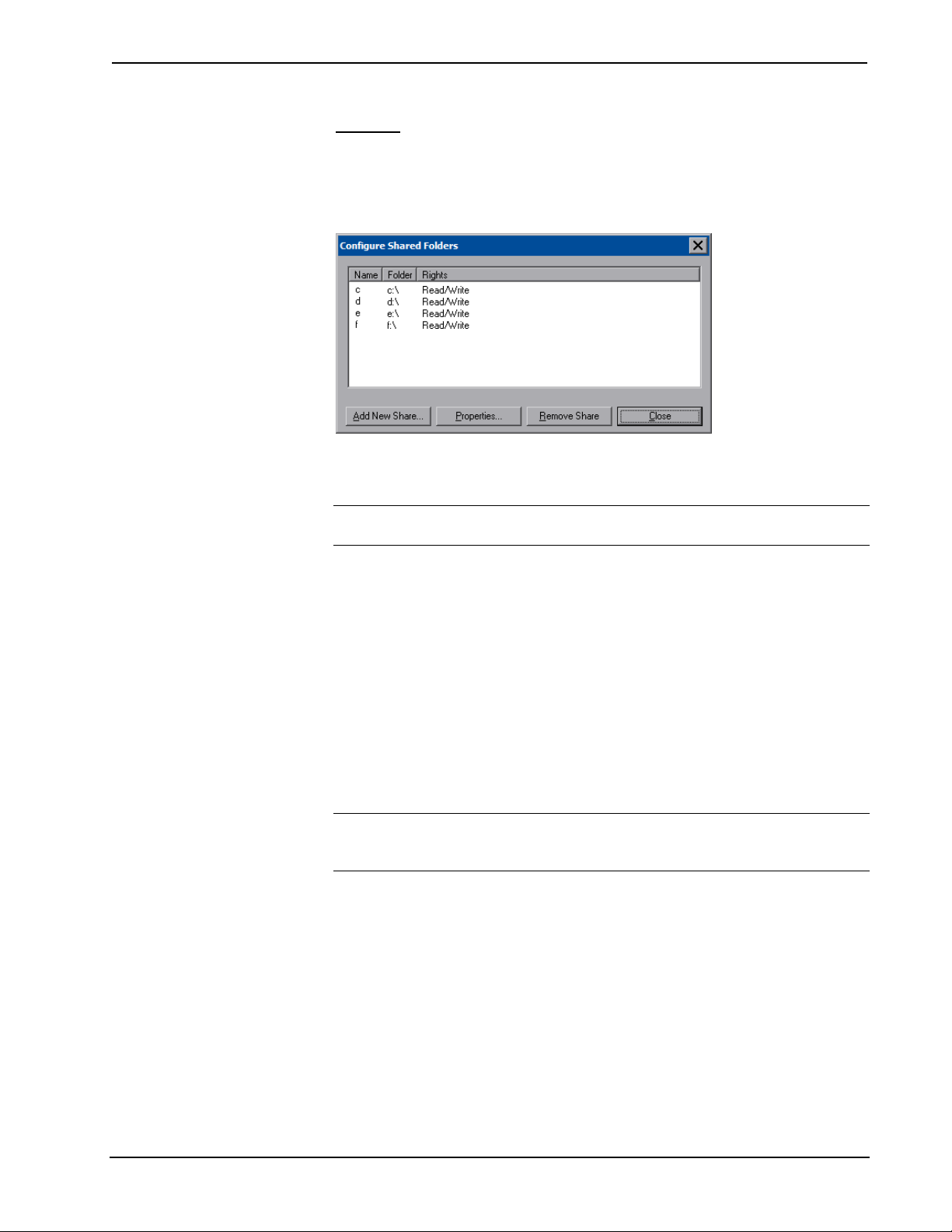
Press Sharing to open the “Configure Shared Folders” window. This window is used
to set up shared folders. Sharing enables remote computers to view and/or modify
files stored on the touchpanel.
“Configure Shared Folders” Window
Click Add New Share… to browse and add directories with permission to read only
or read/write. Click Close after adding all folders to be shared.
NOTE: For security reasons, there is no persistence of the shared drive(s) after the
panel is rebooted.
Battery Details
The Battery section of the setup menu contains a bar graph showing the amount of
charge in the internal battery as well as indicators to show when the battery is
charging and when the TPMC-8X is connected to an AC line.
Standby Details
The Standby function turns off the backlight when the touchpanel is inactive for a
specified time. Use the Up and Down buttons to set the Standby from 0 through 120
minutes, where 0 disables the timeout. Touch the screen to reactivate the touchpanel
from standby mode. When the touchpanel is reactivated, the last screen to be
displayed reappears.
NOTE: The softkeys and hardbuttons will still function when the touchpanel is in
standby mode but will not cause it to awaken from standby. You must touch the
screen to reactivate the touchpanel.
Power Down Details
The Power Down function turns off the touchpanel display, shuts off WiFi and puts
the processor to “sleep” when the touchpanel is inactive for a specified time. Use the
Up and Down buttons to set the Power Down from 0 through 120 minutes, where 0
disables the timeout.
The power button (on the left side of the TPMC-8X) can also be used to manually
put the touchpanel into power down mode. Press and release the power button to
enter power down mode. Use the power button to activate the touchpanel from
power down mode. When the touchpanel is activated, the first page of the project
appears.
44 • Isys i/O™ 8.4” WiFi Touchpanel: TPMC-8X Operations Guide – DOC. 6539B
Crestron TPMC-8X Isys i/O™ 8.4” WiFi Touchpanel
NOTE: When the panel is powered down, it will take less than 10 seconds to power
up and respond to a button press. There is no delay from Standby mode.
NOTE: If the external AC power pack is attached to the touchpanel and plugged
into an active AC receptacle or if the touchpanel is resting in the docking station and
plugged into an active AC receptacle, the panel does not power down when the
Power Down is achieved. Note that the purpose of this timeout is to maximize
battery life. Standby still functions.
Screen Brightness Details
The Screen Brightness can be varied from 0 to 100. To increase the brightness, press
Up. To decrease the brightness, press Down. Lower brightness settings extend
battery life.
WiFi Status Details
The WiFi Status section of the setup menu contains a bar graph showing the strength
of the WiFi signal as well as an indicator to show when the TPMC-8X is
communicating with a wireless access point (AP). SSID, BSSID, IP and MAC
addresses are also shown.
Docking Station Status Details
The Docking Station Status section of the setup menu has two indicators: Docked
Status shows when the touchpanel is mounted in a docking station and Link Status
shows when it is connected to Ethernet via the docking station. IP and MAC
addresses are also shown.
The Release button can be used to release the TPMC-8X from the docking station.
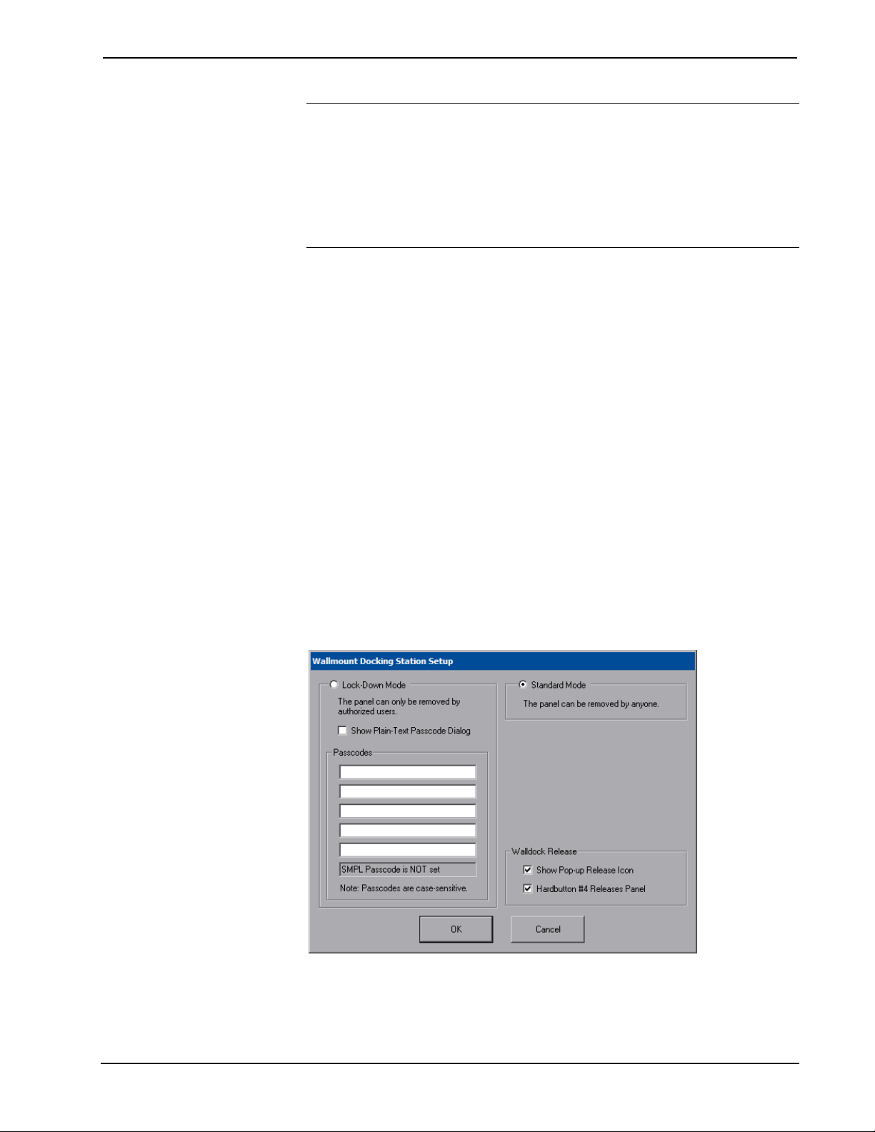
The Configure button will open the “Wallmount Docking Station Setup” window.
“Wallmount Docking Station Setup” Window
In Standard Mode, the panel to be removed from the docking station by anyone. In
Lock-Down Mode, only authorized users can remove the panel from the docking
station by first entering a passcode. The “Wallmount Docking Station Setup”
Operations Guide – DOC. 6539B Isys i/O™ 8.4” WiFi Touchpanel: TPMC-8X • 45
Isys i/O™ 8.4” WiFi Touchpanel Crestron TPMC-8X
window allows the entry of up to five passcodes. (A sixth passcode, created with the
SIMPL Windows program, can be stored in the control system.)
NOTE: If a new SIMPL program is loaded in the control system, the passcode in
the previous program can be cleared by rebooting the touchpanel.
The Show Plain-Text Passcode Dialog checkbox will cause the entered text to
appear instead of asterisks, when a passcode is entered.
In addition, the Show Pop-up Release Icon checkbox makes a release icon available
when a project is views on the touchpanel.
Release Icon
The Hardbutton #4 Releases Panel checkbox can be used to enable or disable button
#4 from releasing the touchpanel from the docking station.
Install Details
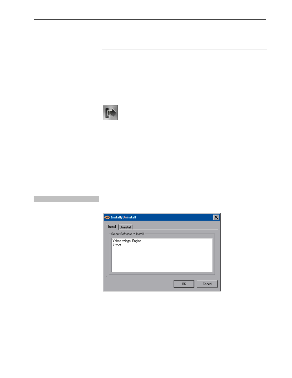
Some third-party software applications (such as Yahoo! Widgets and Skype) are not
pre-installed on the TPMC-8X. The Install button provides facilities for adding these
to your TPMC-8X. It also provides a means for uninstalling these.
There are pre-installation and post-installation procedures that are common to each
application installation process. Begin by following the pre-installation procedures,
then follow the steps unique to each application install and complete the process with
the post-installation procedures.
Pre-installation
Clicking on the Install button will open the “Install/Uninstall” window.
“Install/Uninstall” Window
After selecting the item you wish to install and clicking the OK button, the panel
will display the “Crestron Installation – Warning” window to warn you that the
touchpanel will reboot to prepare for installation and that this will take a few
minutes.
46 • Isys i/O™ 8.4” WiFi Touchpanel: TPMC-8X Operations Guide – DOC. 6539B
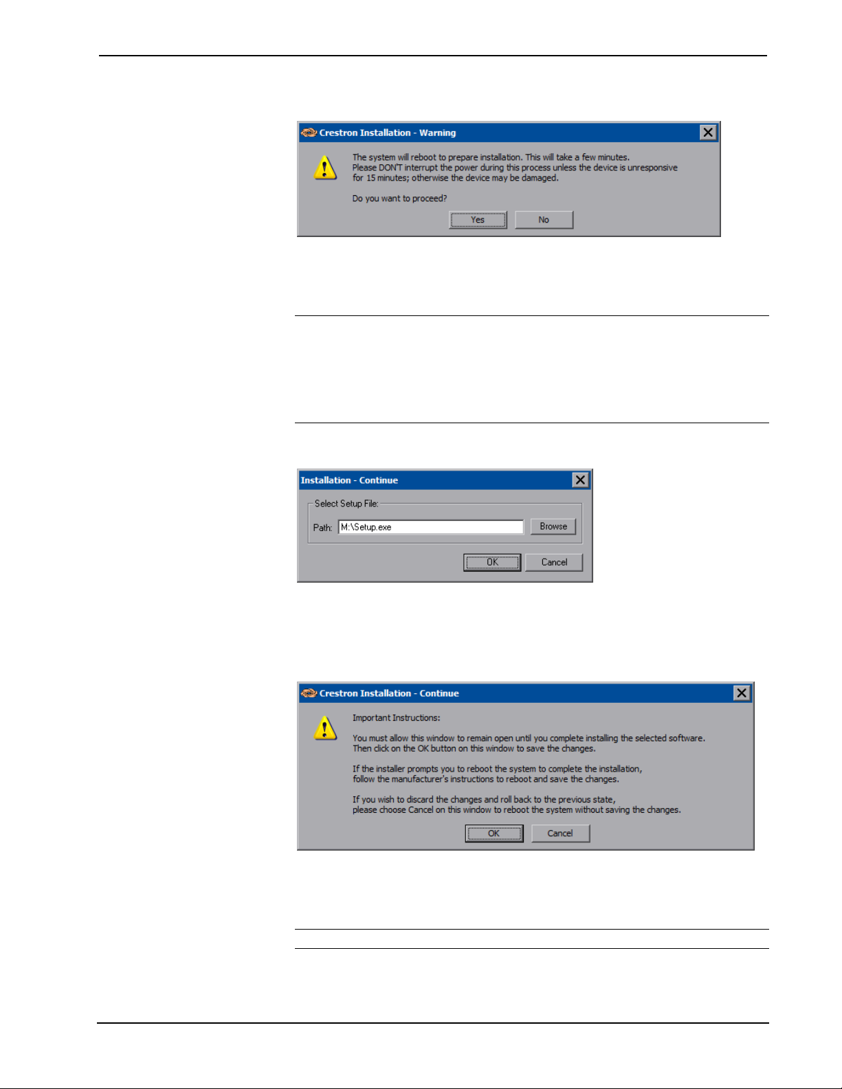
Crestron TPMC-8X Isys i/O™ 8.4” WiFi Touchpanel
“Crestron Installation – Warning” Window
Click Yes and the “Installation – Continue” window will open. This window
contains a Browse button to allow you to navigate to the location of the application
you want to install. Installation files can be on a flash card or a network drive.
NOTE: If there is a mapped network drive on the touchpanel, the first time you
select Browse, it may take some time for the “Open” window to appear.
NOTE: Crestron recommends that you copy installation files to a flash card or a
USB drive connected to the touchpanel prior to installation and perform the
installation from one of these.
“Installation – Continue” Window
When you have browsed to and selected the desired installation file, the path to the
file will show in the Select Setup File section of the window. Click OK to open the
“Crestron Installation - Continue” window.
“Crestron Installation – Continue” Window
The “Crestron Installation – Continue” window is used after installation is complete.
It will allow you to validate the install and commit the changes. This window also
allows you to cancel an installation and discard any changes.
NOTE: Do not click OK until the installation of the selected software is complete.
Operations Guide – DOC. 6539B Isys i/O™ 8.4” WiFi Touchpanel: TPMC-8X • 47
Isys i/O™ 8.4” WiFi Touchpanel Crestron TPMC-8X
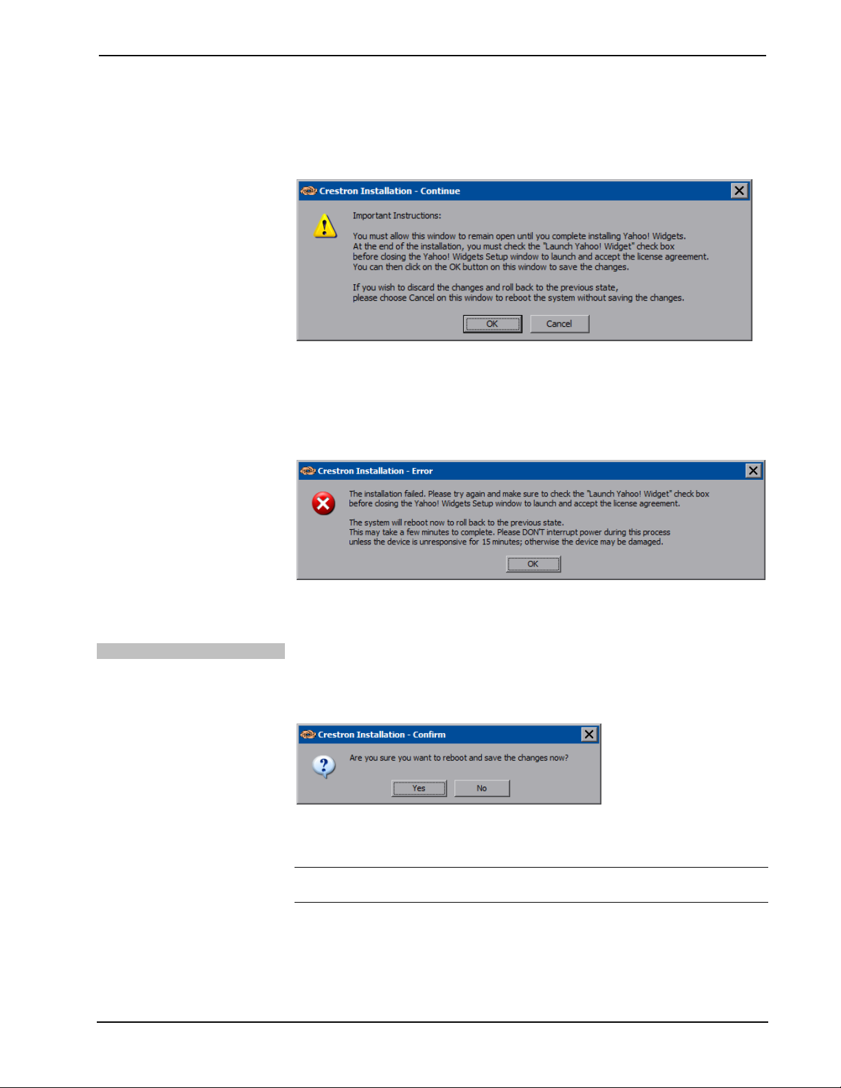
When installing Yahoo! Widgets, a different “Creston Installation – Continue”
window will appear instead (refer to the following illustration), with specific
instructions for this application.
“Crestron Installation – Continue” Window for Yahoo! Widgets
If you forget to check the Launch Yahoo! Widget checkbox, the installation will fail
and you will see the “Crestron Installation – Error” window (refer to the following
illustration), which will ask you to try again and to remember to check the Launch
Yahoo! Widget checkbox and accept the license agreement.
“Crestron Installation – Error” Window for Yahoo! Widgets
Proceed with the directions for the particular software you are installing (for
“Yahoo! Widgets” and “Skype”, refer to the following page). Then return to the
post-installation procedure below to complete the process.
Post-installation
When installation program is complete, click OK in the “Crestron Installation –
Continue” window. The “Crestron Installation – Confirm” window will appear
asking you if you want to reboot and save the changes. Click Yes.
“Crestron Installation – Confirm” Window
The final window will be the “Crestron Installation – Save” window to inform you
the system will reboot twice to commit the changes.
NOTE: This may take a few minutes to complete and should not be interrupted
unless the device is unresponsive for 30 minutes.
48 • Isys i/O™ 8.4” WiFi Touchpanel: TPMC-8X Operations Guide – DOC. 6539B

Crestron TPMC-8X Isys i/O™ 8.4” WiFi Touchpanel
“Crestron Installation – Save” Window
After the second reboot, software installation is complete.
Installing Yahoo Widget Engine
Follow the instructions on the manufacturer’s website or those that came with your
software.
When installing the software, consider the following:
• If the installation software asks you if you wish to install the Yahoo Toolbar
or Yahoo Central, be sure to leave the checkboxes blank (i.e. unchecked) as
these are not supported by the TPMC-8X. Then click Next.
• If the installation software asks you if you wish to set your homepage to
www.yahoo.com
be sure to leave the checkboxes blank (i.e. unchecked) as these are not
supported by the TPMC-8X. Then click Install.
or if you wish to set your default search engine to Yahoo,
• If the installation software asks you if you wish to launch the Yahoo Widget
Engine, be sure to put a check in the checkbox and accept the license
agreement. Then click Close.
To complete the final installation steps, follow the procedure in the
“Post-installation” section (refer to page 48).
NOTE: If a popup message appears asking you to install the latest version of
Yahoo! Widgets, click Skip, then, from the main Setup Menu, click Save & Reboot.
NOTE: For information on how to program Yahoo! Widgets in the TPMC-8X, refer
to the help file in VT Pro-e version 3.7.2.8 or later.
Installing Skype
Follow the instructions on the manufacturer’s website or those that came with your
software.
When installing the software, consider the following:
• If the installation software asks you if you wish to create a desktop icon or
if you wish to Start Skype when the computer starts, be sure to leave the
checkboxes blank (i.e. unchecked) as these are not supported by the
TPMC-8X. Then click Next.
• If the installation software displays a Launch Skype checkbox, be sure to
leave the checkbox blank (i.e. unchecked). Then click Finish.
To complete the final installation steps, follow the procedure in the
“Post-installation” section (refer to page 48).
NOTE: For information on how to program Skype in the TPMC-8X, refer to the
help file in VT Pro-e version 3.7.2.8 or later.
Operations Guide – DOC. 6539B Isys i/O™ 8.4” WiFi Touchpanel: TPMC-8X • 49

Isys i/O™ 8.4” WiFi Touchpanel Crestron TPMC-8X
Save & Reboot and Shut Down Details
To save any changes and reboot the touchpanel, press Save & Reboot, located in the
lower right section of the setup menu.
To turn off the touchpanel, press Shut Down, located in the lower right section of
the setup menu. This is the recommended method for shutting down the touchpanel.
After the touchpanel has shut down, the power supply can be safely removed from
the touchpanel.
Exit Details
Press Exit to leave the setup menu and return to the project. If no project has been
loaded, the touchpanel will display an error message and return to the setup menu.
50 • Isys i/O™ 8.4” WiFi Touchpanel: TPMC-8X Operations Guide – DOC. 6539B
Crestron TPMC-8X Isys i/O™ 8.4” WiFi Touchpanel
Hardware Hookup
Ventilation
Connect the Device
The TPMC-8X should be used in a well-ventilated area.
To prevent overheating, do not operate this product in an area that exceeds the
environmental temperature range listed in the table of specifications.
When making connections to the TPMC-8X, consider the following:
• Use the included Crestron power supply for these devices.
• The power supply cable cannot be extended.
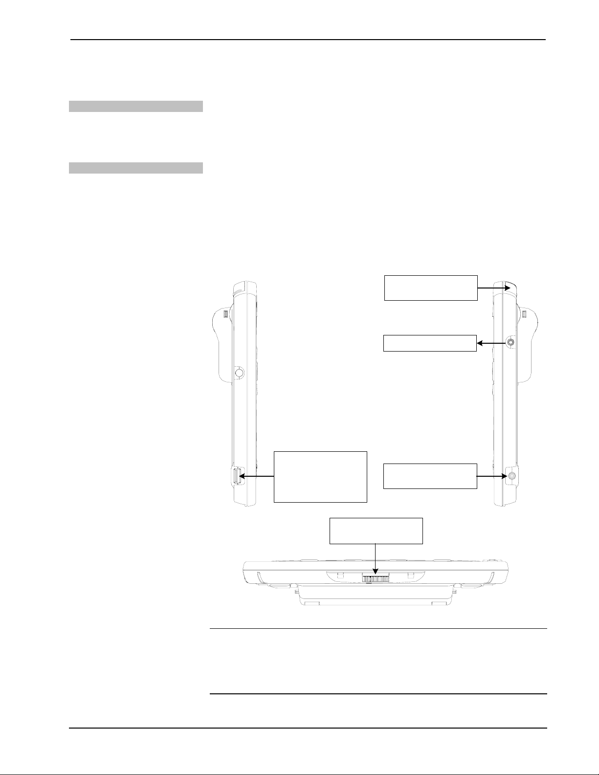
Hardware Connections for the TPMC-8X
Left Side View
COMPACT FLASH
CARD SLOT
HEADPHONES
Right Side View
USB: FROM
KEYBOARD OR
OTHER WIRED
DEVICE
DOCKING STATION
CONNECTOR*
12V 3.5A:
AC POWER PACK*
Bottom View
* These connectors are optional for powering the device.
CAUTION: Do not apply excessive pressure to the touchscreen display during
handling. Doing so can crack the screen and damage the touchpanel.
NOTE: When inserting a Compact Flash card, orient the card so that the small lip at
the top of the card is facing away from the touchpanel.
Operations Guide – DOC. 6539B Isys i/O™ 8.4” WiFi Touchpanel: TPMC-8X • 51

Isys i/O™ 8.4” WiFi Touchpanel Crestron TPMC-8X
Recommended Cleaning
Keep the surface of the touchscreen free of dirt, dust or other materials that could
degrade optical properties. Long-term contact with abrasive materials can scratch the
surface, which may detrimentally affect image quality.
For best cleaning results use a clean, damp, non-abrasive cloth with any
commercially available non-ammonia glass cleaner. Bezels may not provide a
complete watertight seal. Therefore, apply cleaning solution to the cloth rather than
the surface of the touchscreen. Wipe touchscreen clean and avoid getting moisture
beneath the bezels.
52 • Isys i/O™ 8.4” WiFi Touchpanel: TPMC-8X Operations Guide – DOC. 6539B

Crestron TPMC-8X Isys i/O™ 8.4” WiFi Touchpanel
Programming Software
Have a question or comment about Crestron software?
Answers to frequently asked questions (FAQs) can be viewed in the Online Help
section of the Crestron website. To post a question or view questions you have
submitted to Crestron’s True Blue Support, log in at http://support.crestron.com.
First-time users will need to establish a user account.
Earliest Version Software Requirements for the PC
NOTE: Crestron recommends that you use the latest software to take advantage of
the most recently released features. The latest software is available from the Crestron
website.
Crestron has developed an assortment of Windows-based software tools to support
a controlled system. For the minimum recommended software versions, visit the
Version Tracker page of the Crestron website (www.crestron.com/versiontracker
).
Configuration Manager
Programming with Crestron SystemBuilder
Crestron SystemBuilder is the easiest method of programming but does not offer as
much flexibility as SIMPL Windows. For additional details, download
SystemBuilder from the Crestron website and examine the extensive help file.
Programming with SIMPL Windows
NOTE: While SIMPL Windows can be used to program the TPMC-8X, it is
recommended to use SystemBuilder for configuring a system.
SIMPL Windows is Crestron’s premier software for programming Crestron control
systems. It is organized into two separate but equally important “Managers”.
Configuration Manager is the view where programmers “build” a Crestron control
system by selecting hardware from the Device Library.
• To incorporate the TPMC-8X into the system, drag the TPMC-8X from the
Touchpanels | Touchpanels (Ethernet) folder of the Device Library and drop
it in the System Views.
Operations Guide – DOC. 6539B Isys i/O™ 8.4” WiFi Touchpanel: TPMC-8X • 53

Isys i/O™ 8.4” WiFi Touchpanel Crestron TPMC-8X
Locating the TPMC-8X in the Device Library
• The system tree of the control system displays the device in the appropriate
slot with a default IP ID as shown in the following illustration.
C2Net Device, Slot 8
• Additional TPMC-8X devices are assigned different IP ID numbers as they
are added.
• If necessary, double click a device to open the “Device Settings” window
and change the IP ID, as shown in the following figure.
54 • Isys i/O™ 8.4” WiFi Touchpanel: TPMC-8X Operations Guide – DOC. 6539B

Crestron TPMC-8X Isys i/O™ 8.4” WiFi Touchpanel
p
“TPMC-8X Device Settings” Window
• The ID code specified in the SIMPL Windows program must match the IP
ID of each unit.
Program Manager
Multi-mode objects offer high-
erformance programming!
Program Manager is the view where programmers “program” a Crestron control
system by assigning signals to symbols. The symbol can be viewed by double
clicking on the icon or dragging it into Detail View. Each signal in the symbol is
described in the SIMPL Windows help file (F1).
Programming with VisionTools Pro-e
Touchpanel screens should be created in VisionTools Pro-e to allow accessing the
embedded applications, switching of source signals to desired outputs as well as
selection of the system mode. There are no special programming requirements to use
the functions of the TPMC-8X in a room-control system.
Multi-Mode Objects
The single most-advanced VisionTools Pro-e high-performance programming
technique involving the TPMC-8X is the concept of multi-mode objects. A multimode object (i.e. button, legend, etc.) is an object drawn on a VisionTools Pro-e
page that can have one or more active and inactive visible settings (modes).
For examples, refer to www.crestron.com/exampleprograms
mode object examples. This file contains the VisionTools Pro-e touchpanel files and
SIMPL Windows files that illustrate the high-performance capabilities of multi-mode
objects.
WAV File Audio Messages
and search for multi-
The TPMC-8X touchpanels are capable of playing audio messages as system
prompts and responses. These files are recorded as WAV files on a PC using an
audio utility such as Sound Recorder that is packaged with Microsoft Windows
95/98/Me/XP/NT/2000/Vista™. Files from other sources may also be converted to
an acceptable format by using this or a similar utility. Many other audio utilities are
available commercially or as shareware. The TPMC-8X touchpanels accept the
following WAV file formats: PCM, 8 – 44.1 kHz, mono & stereo, 8 & 16 bit. For
Operations Guide – DOC. 6539B Isys i/O™ 8.4” WiFi Touchpanel: TPMC-8X • 55

Isys i/O™ 8.4” WiFi Touchpanel Crestron TPMC-8X
more information about how to use Sound Recorder, refer to its User’s Guide and
extensive help information provided with the software. Also refer to the help file in
VisionTools Pro-e to learn how to use its audio tool, Sound Manager, to attach WAV
files to a touchpanel project.
Pre-recorded WAV files for voice prompts and responses are available from
Crestron. These files can be stored into and programmed for use in the touchpanel
directly or may be edited with the Sound Recorder. For example, the individual files
can be combined to create custom messages.
NOTE: Touchpanel WAV files can be obtained from the Wave LC Library of the
Crestron FTP site.
Bit Depth and File Size
A bit depth refers to the number of memory bits used to store color data for each
pixel in a raster image. A touchpanel raster image consists of a rectangular grid of
picture elements (pixels). Each pixel uses the same amount of memory to store its
color data. The amount of memory is called the bit depth of the image.
Greater bit depths are required to represent finer gradations of color. Increasing bit
depth necessarily increases file size. A black and white drawing requires only one bit
per pixel to store all the available color information. Using a 32-bit per pixel bit
depth for a black and white image increases the file size 32 times without adding
anything to the black and white image quality.
In an 8-bit per pixel system, the associated 8-bits of video memory for every screen
pixel contain a value referring to a location in an 8-bit color table. In this way any
one of the specific 256 color table locations is assigned to a pixel.
A 16-bit highcolor system is considered sufficient to provide life-like colors. It is
encoded using 5-bits to represent red, 5-bits to represent blue and (since the human
eye is more sensitive to the color green) 6-bits to represent 64 levels of green. These
can therefore be combined to provide 65,536 mixed colors (32 x 32 x 64 = 65,536).
In a 24-bit graphics display, the video memory allocates 24 bits for each pixel on the
screen enabling each pixel to take on any one of a possible 16.7 million colors. Each
24-bit value is composed of 8-bits for red, 8-bits for green and 8-bits for blue. These
triplets of 8-bit values are also referred to as the red, green and blue color planes. A
24-bit image is actually composed of three component images which combine to
create the truecolor picture. The reason this is called truecolor is that this is near the
maximum number of colors the human eye is able to detect.
Truecolor images are sometimes represented by a 32-bit value. The extra 8-bits do
not enhance the precision of the color representation but act as an alpha channel that
represents pixel translucence. 32-bit truecolor has become popular on the computer
desktop to provide effects such as translucent windows, fading menus and shadows.
In graphics intensive applications such as touchpanels, raising or lowering the color
depth of the displayed graphics can achieve a balance of performance and quality.
Lower color depths do not require as much frame buffer memory or display
bandwidth, allowing them to be generated and displayed more quickly. Increasing
color depth results in higher color quality at the expense of display speed and
responsiveness. By using mostly 8-bit or 16-bit graphics and holding 32-bit graphics
to a minimum (e.g. for a family photo, etc.), you can create a sophisticated project
that will fit in the memory space provided and have the touchpanel remain very
responsive.
56 • Isys i/O™ 8.4” WiFi Touchpanel: TPMC-8X Operations Guide – DOC. 6539B

Crestron TPMC-8X Isys i/O™ 8.4” WiFi Touchpanel
Relationship of Bits to Colors
NUMBER OF BITS NUMBER OF COLORS
1 bit Black and White
2 bits 4 Colors
4 bits 16 Colors
8 bits 256 Colors
16 bits 65,536 Colors (Highcolor)
24 bits 16.7 million Colors (Truecolor)
32 bits 16.7 million Colors plus Transparency
When creating a VisionTools Pro-e project you can elect to compress and reduce the
image size in the “Page Properties” window for the entire page and/or perform the
same function of reducing the image size using the “Image Properties” window. A
reduction in image size will save a considerable amount of memory space for your
project.
In VisionTools Pro-e, the Compress checkbox permits the image to be compressed
when compiling. The 16 Bits checkbox converts a 24-bit or 32-bit image to 16 bits.
This conversion to a 16-bit image may cause the loss of some subtle shading. To
compensate for this, use the dithering to simulate the original shading. Various
dithering types are available. Refer to the following illustrations.
VT Pro-e “Page Properties” Window – Bit Depth Selection VT Pro-e “Image Properties” Window – Bit Depth Selection
MultiByte International Characters
Most languages use a single byte of eight bits to represent a character, e.g. English,
French, German, Hebrew, Russian, Thai, etc.
Multibyte character fonts require more than the usual eight bits to specify a
character. This occurs when a language has more than 256 characters (2
8
) in a font.
For example, Chinese fonts contain several thousand characters. Other multibyte
languages include Japanese and Korean.
Operations Guide – DOC. 6539B Isys i/O™ 8.4” WiFi Touchpanel: TPMC-8X • 57

Isys i/O™ 8.4” WiFi Touchpanel Crestron TPMC-8X
There are two separate applications with multibyte characters – static text on buttons
and indirect text on buttons. No Isys i/O touchpanel firmware changes are required in
either case.
Indirect text on a button is entered in VisionTools Pro-e and the actual string to be
displayed is entered in SIMPL Windows. As of this publication date only completely
single byte or completely multibyte strings may be entered or they will not be
compiled correctly in SIMPL Windows. In other words, you cannot enter Chinese
characters interspersed with numbers. You can enter Chinese characters or numbers
in separate strings or you can pad each number with “\x00” to make it multibyte and
then combine it with Chinese characters in the same string.
Of course you can always use the workaround of showing a graphic that displays the
string but it is not dynamic. To compile and use multibyte characters it is essential
that the operating system understand the language. Windows XP and Vista are
available in many international languages and add-on software is available for other
versions of Windows.
Embedded Applications
A number of third-party or in-house applications are embedded in a VT Pro-e
TPMC-8X project. (Refer to illustration on the following page.)
• Adobe Reader
• Microsoft Excel Viewer
• Microsoft Internet Explorer
• Microsoft Word Viewer
• MJPEG Viewer
• NetMeeting
• PowerPoint Viewer
• Real Player
• Remote Desktop
• Skype
• VNC Viewer
• Windows Media Player
• WordPad
The embedded applications have the following features:
• All embedded applications listed in the VT Pro-e ProjectView
workspace are created by default for a new TPMC-8X project.
• All applications are created at project-level – one instance per project.
• The static position and size of each application can be viewed from any
page.
• Four analog joins can be assigned to each application to dynamically
change position and size.
• One digital feedback join or one analog join can be assigned to
dynamically show/hide an application.
58 • Isys i/O™ 8.4” WiFi Touchpanel: TPMC-8X Operations Guide – DOC. 6539B

Crestron TPMC-8X Isys i/O™ 8.4” WiFi Touchpanel
Embedded Applications in ProjectView
Right-click on any of the applications in the Project View and select Properties to
open the “Embedded Application Property” window (refer to the illustration below).
This window permits a choice of positions on the screen, assignment of an analog
touch join type and number and a show/hide join number.
Defaults for Embedded Windows Applications
Use the Default Path text box in the “Embedded Applications Properties” window to
enter the default document for the application.
Edit the Default Position and Size in the “Embedded Application Properties”
window to point to your new location.
Sample of an “Embedded Application Properties” Window
Operations Guide – DOC. 6539B Isys i/O™ 8.4” WiFi Touchpanel: TPMC-8X • 59
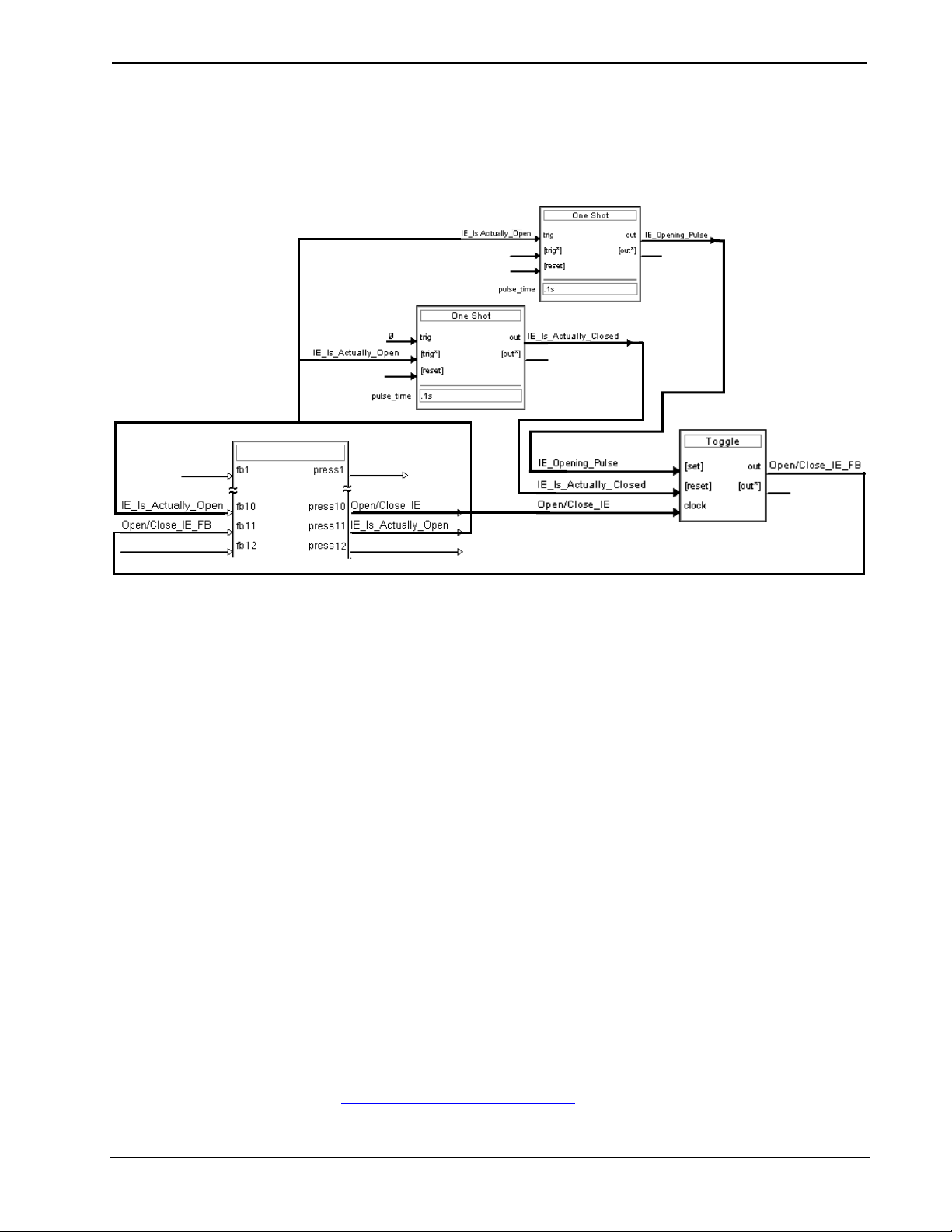
Isys i/O™ 8.4” WiFi Touchpanel Crestron TPMC-8X
Programming Embedded Windows Applications
The following diagram is an example of a basic SIMPL program that enables you to
open/close an embedded application. The example program is discussed following
the diagram.
TPMC-8X (Digitals)
The example has Join #10 assigned to a button that is used to toggle the state of
Internet Explorer. Press10 is routed to the clock line of a Toggle symbol. The output
of the toggle is routed to fb11. Join #11 is referred to as the "Open/Close State
Digital Join.” The feedback signal of the Open/Close State Digital Join is used to
Open/Close the application. In this example, when fb11 goes high, Internet Explorer
opens, and when fb11 goes low, Internet Explorer closes. However, since the
application can also be closed by pressing the "X" in the upper right hand corner of
Internet Explorer, we must keep the logic synchronized. If we do not, the toggle will
get out of sync. Similarly, using the reserved join to launch the embedded application
would result in the application being open, but the state of the toggle remaining low,
so a one-shot is used to set the state of the toggle if the embedded application is
opened in this way.
For example, the user presses button #10 and the output of the toggle
(<Open/Close_IE_FB>) is high. If the user presses the "X" on IE, IE closes. The
next time they touch button #10, <Open/Close_IE_FB> will go low, which tries to
close the application. However, the application is already closed. We need to reset
the state of the toggle to keep in sync with the actual state of the application.
The “Press” signal of the Open Close State Digital Join can be used to know the true
state of the application. When Press11 goes high, in this example, IE is open. When
Press11 goes low, IE is closed. Here, we use the falling edge of Press11 through a
One-Shot to reset the state of the Toggle symbol. Now the toggle is properly
synchronized if the user closes the application from the panel itself.
Example Program
An example program for the TPMC-8X is available from the Crestron website
(www.crestron.com/exampleprograms
60 • Isys i/O™ 8.4” WiFi Touchpanel: TPMC-8X Operations Guide – DOC. 6539B
).

Crestron TPMC-8X Isys i/O™ 8.4” WiFi Touchpanel
Uploading and Upgrading
Crestron recommends using the latest programming software and that each device
contains the latest firmware to take advantage of the most recently released features.
However, before attempting to upload or upgrade it is necessary to establish
communication.
Establishing Communication
Use Crestron Toolbox for communicating with the TPMC-8X; refer to the Crestron
Toolbox help file for details. There is a single method of communication: TCP/IP
communication.
NOTE: Required for operation with a Crestron control system.
Ethernet Communication
PC RUNNING
CRESTRON TOOLBOX
WIRELESS ETHERNET
WIRELESS
(OR WIRED USING
ETHERNET
OPTIONAL DOCKING
STATION/CHARGER)
TPMC-8X
• Enter the IP address, Subnet mask and Default gateway of the TPMC-8X in
the “Internet Protocol (TCP/IP) Properties” window (refer to “Ethernet
Details” which starts on page 36).
• Confirm Ethernet connections between TPMC-8X and PC.
• Use the Address Book in the Crestron Toolbox to create an entry for the
TPMC-8X with the TPMC-8X’s TCP/IP communication parameters.
• Display the “System Info” window (click the
icon) and select the
TPMC-8X entry.
Programs, Projects and Firmware
Program, project or firmware files may be distributed from programmers to installers
or from Crestron to dealers. Firmware upgrades are available from the Crestron
website as new features are developed after product releases. One has the option to
upload programs and projects via the programming software or to upload and
upgrade via the Crestron Toolbox. For details on uploading and upgrading, refer to
the SIMPL Windows help file, VisionTools Pro-e help file or the Crestron Toolbox
help file.
SIMPL Windows
If a SIMPL Windows program is provided, it can be uploaded to the control system
using SIMPL Windows or Crestron Toolbox.
VisionTools Pro-e
Upload the VisionTools Pro-e file to the touchpanel using VisionTools Pro-e or
Crestron Toolbox. If loading a project to a touchpanel that has an external compact
flash slot, please use Crestron Toolbox.
Firmware
Check the Crestron website to find the latest firmware. (New users may be required
to register to obtain access to certain areas of the site, including the FTP site.)
Operations Guide – DOC. 6539B Isys i/O™ 8.4” WiFi Touchpanel: TPMC-8X • 61

Isys i/O™ 8.4” WiFi Touchpanel Crestron TPMC-8X
Upgrade TPMC-8X firmware via Crestron Toolbox.
• Establish serial or TCP/IP communications with the TPMC-8X and display
the “System Info” window.
• Select Functions | Firmware… to upgrade the TPMC-8X firmware.
Program Checks
In Crestron Toolbox, display the “System Info window (click the
select the Functions menu to display actions that can be performed on the
TPMC-8X.
Be sure to use the Crestron Toolbox to create the TPMC-8X IP table.
• Select Functions | IP Table Setup.
• Add, modify or delete entries in the IP table. The TPMC-8X can have only
one IP table entry.
• A defined IP table can be saved to a file or sent to the device.
Edit the control system’s IP table to include an entry for the TPMC-8X. The entry
should list the TPMC-8X’s IP ID (specified on the TPMC-8X’s IP table) and the
internal gateway IP address 127.0.0.1.
To prevent interference with other 802.11 devices that may be operating nearby,
channels should be adequately spaced when configuring your wireless network;
channels 1, 6 and 11 are the only non-overlapping channels. Refer to the information
supplied with the WAP for instructions concerning channel selection.
icon) and
62 • Isys i/O™ 8.4” WiFi Touchpanel: TPMC-8X Operations Guide – DOC. 6539B

Crestron TPMC-8X Isys i/O™ 8.4” WiFi Touchpanel
Operation
Power Options
The TPMC-8X can be powered in the following ways:
• TPMC-8X-BTP Internal Battery Pack (included)
• TPMC-8X-BTPE External Battery Pack (sold separately)
• TPMC-8X-DS Desktop Docking Station/Charger (sold separately)
• TPMC-8X-DSW Wall Mount Docking Station/Charger (sold separately)
The internal and external batteries can be charged by using the included AC power
pack, by connecting the TPMC-8X to the optional Docking Station/Charger
(TPMC-8X-DS) when it is connected to AC power or by connecting the TPMC-8X
to the optional Wall Mount Docking Station/Charger (TPMC-8X-DSW).
The TPMC-8X has four power modes: On, Standby, Power Down and Off. Refer to
the following table for details.
TPMC-8X Power Modes
POWER MODE DETAILS
On
Standby
Power Down
Off
* Standby, power down and power off modes can also be initiated using reserve join numbers in
VisionTools Pro-e and the Device Extender function in SIMPL Windows. For details, refer to the
respective help files in these programs.
Normal operating mode. Initiated with
power button on left side of touchpanel.
Backlight is turned off to conserve battery
power but WiFi and processor are still on
and hardbuttons and softkeys are still
functional. Initiated with Standby function
from the setup menu.* Touch the screen to
reactivate the TPMC-8X from standby
mode.
Backlight is turned off, WiFi is turned off
and the internal processor is put into “sleep”
mode to conserve battery power. Initiated
with Power Down function from the setup
menu or by momentarily pressing the power
button on the left side of the touchpanel.*
The TPMC-8X can be activated from power
down mode by pressing the power button
on the left side of the touchpanel.
All power is off. Can be initiated by pressing
the power button on the left side of the
touchpanel and holding it for four seconds.
However, the recommended method for
shutting down the touchpanel is to press
the Shut Down button on the setup menu.*
Operations Guide – DOC. 6539B Isys i/O™ 8.4” WiFi Touchpanel: TPMC-8X • 63

Isys i/O™ 8.4” WiFi Touchpanel Crestron TPMC-8X
Charging the Internal Battery
NOTE: A Lithium Ion (Li-Ion) battery typically provides 300-500 charge/discharge
cycles.
There are three ways to charge the TPMC-8X-BTP Internal Battery Pack:
• With the TPMC-8X-BTP installed in the TPMC-8X touchpanel, connect the
touchpanel to an AC source using its AC adapter or
• With the TPMC-8X-BTP installed in the TPMC-8X touchpanel, mount the
touchpanel on an AC powered TPMC-8X-DS Docking Station/Charger
(sold separately) or
• With the TPMC-8X-BTP installed in the TPMC-8X touchpanel, mount the
touchpanel on a TPMC-8X-DSW Wall Mount Docking Station/Charger
(sold separately).
NOTE: The battery pack may take up to three hours to charge in a powered
touchpanel if the panel is in use during charging.
NOTE: When the external battery pack (TPMC-8X-BTPE, sold separately) is
attached, both the internal and external battery packs charge simultaneously.
Security Infrastructure
Since the TPMC-8X does not use a traditional hard drive but rather an image that
gets restored every time the touchpanel is rebooted, any virus infection is cleared
immediately after a reboot. However, using the currently available tools and
techniques, Crestron has provided an infrastructure that protects against possible
virus infections.
1. Executables/Scripts brought in on external media
The implementation of the TPMC-8X has restrictions on starting any application
or script. The only applications that can be started are those allowed by Crestron
and these can only be started from the Crestron project.
2. Downloaded Program/Script
The browser is customized in such a way that files cannot be downloaded. The
only files the browser can open are the files it has plug-ins for, such as PDF, etc.
The user cannot change the options, as this dialog box has been disabled.
3. Browser Hijack and Browser vulnerability
Crestron has patched all currently known hijacks and vulnerabilities. Future
updates can be downloaded from the Crestron website.
4. Email Viruses
There is no e-mail client installed on the TPMC-8X, so email-based viruses
cannot be executed.
5. Viruses that attack web/FTP servers
The TPMC-8X does not run a web or FTP server and is therefore not listening to
port 21 or 80. The only ports the system listens to are the ports registered to
Crestron.
6. Virus from other machines on the network
Since drives on the TPMC-8X can be shared on the network, it is possible that a
virus can write itself to files/folders on these shares. Our recommendation
64 • Isys i/O™ 8.4” WiFi Touchpanel: TPMC-8X Operations Guide – DOC. 6539B

Crestron TPMC-8X Isys i/O™ 8.4” WiFi Touchpanel
therefore is to share as "Read-Only," so that viruses cannot attach themselves to
files on the TPMC-8X.
7. ActiveX and Java
The TPMC-8X has ActiveX disabled and has no Java Virtual Machine installed.
These applets cannot run on the TPMC-8X.
NOTE: While browsing the Internet with the TPMC-8X, clicking on a link may
cause a message box titled "Restrictions" to appear that contains the text "This
operation has been cancelled due to restrictions in effect on this computer. Please
contact your system administrator." If this message appears, checking Enable Popup
Windows in the “Embedded Apps” section of the setup menu may correct this error.
Other restrictions may also cause this error, so this may not prevent all occurrences.
NOTE: Security settings and restrictions can be changed via the Embed Apps
button on the setup menu. Refer to “Embed Apps (Embedded Applications)” which
starts on page 19 for details.
Operations Guide – DOC. 6539B Isys i/O™ 8.4” WiFi Touchpanel: TPMC-8X • 65

Isys i/O™ 8.4” WiFi Touchpanel Crestron TPMC-8X
Problem Solving
Troubleshooting
The following table provides corrective action for possible trouble situations. If
further assistance is required, please contact a Crestron customer service
representative.
TPMC-8X Troubleshooting
TROUBLE POSSIBLE CAUSE(S) CORRECTIVE ACTION
Touchpanel does
not turn on.
Cannot upload VT
Pro-e project or
firmware from
Toolbox via WiFi.
TPMC-8X does
not show
feedback and/or
does not control
any devices.
Battery was not charged
or is discharged.
TPMC-8X is off, in
power down mode or
has no power.
No WAPs
defined/selected on the
TPMC-8X.
No IP address
configured/obtained on
the TPMC-8X.
TPMC-8X is out of
range or has poor
access to the WAPs.
No WAPs
defined/selected on the
TPMC-8X.
Place the TPMC-8X on the
docking station and charge
the battery using the provided
power pack.
Verify that TPMC-8X has
power and is on or in standby
mode.
Refer to the “Ethernet Details”
section of this guide, which
starts on page 36 to
define/select WAPs.
Refer to “Ethernet Details”
which starts on page 36 to
define IP addresses. If the
TPMC-8X is set up to use
DHCP (not recommended),
you can use the WAP window
box to verity the IP address
provided. If the number is
invalid for your subnet or no
number is present, verify that
the DHCP server is working
properly.
The TPMC-8X is out of range
of the WAP or is experiencing
interference. Refer to the
WAP documentation for
instructions on setting up a
wireless network with
minimum interference and no
dead spots.
Refer to the “Ethernet Details”
section of this guide, which
starts on page 36 to
define/select WAPs.
(Continued on following page)
66 • Isys i/O™ 8.4” WiFi Touchpanel: TPMC-8X Operations Guide – DOC. 6539B

Crestron TPMC-8X Isys i/O™ 8.4” WiFi Touchpanel
TPMC-8X Troubleshooting (Continued)
TROUBLE POSSIBLE CAUSE(S) CORRECTIVE ACTION
TPMC-8X does
not show
feedback and/or
does not control
any devices.
(Continued)
TMPC-8X shows
unexpected or
intermittent
feedback and/or
has intermittent
device control.
TPMC-8X boots
up in setup
screens every
time.
No IP address
configured/obtained on
the TPMC-8X.
Invalid control system IP
address / IP ID set up
on TPMC-8X.
TPMC-8X is out of
range or has poor
access to the WAPs.
TPMC-8X is out of
range or has poor
access to the WAPs.
Invalid VT Pro-e project
or no VT Pro-e project is
loaded.
Refer to “Ethernet Details”
which starts on page 36 to
define IP addresses. If the
TPMC-8X is set up to use
DHCP (not recommended),
you can use the WAP window
box to verity the IP address
provided. If the number is
invalid for your subnet or no
number is present, verify that
the DHCP server is working
properly.
The IP address (or host
name) for the control system
is invalid or the IP ID does not
match the one defined in the
SIMPL program. Refer to “IP
Table” which starts on page
42 to define IP addresses.
The TPMC-8X is out of range
of the WAP or is experiencing
interference. Refer to the
WAP documentation for
instructions on setting up a
wireless network with
minimum interference and no
dead spots.
The TPMC-8X is out of range
of the WAP or is experiencing
interference. Refer to the
WAP documentation for
instructions on setting up a
wireless network with
minimum interference and no
dead spots.
Load/reload VT Pro-e project
using the Toolbox.
Reference Documents
The latest version of all documents mentioned within the guide can be obtained from
the Crestron website (www.crestron.com/manuals
). This link will provide a list of
product manuals arranged in alphabetical order by model number.
List of Related Reference Documents
DOCUMENT TITLE
2-Series Control Systems Reference Guide
Further Inquiries
If you cannot locate specific information or have questions after reviewing this
guide, please take advantage of Crestron's award winning customer service team by
Operations Guide – DOC. 6539B Isys i/O™ 8.4” WiFi Touchpanel: TPMC-8X • 67

Isys i/O™ 8.4” WiFi Touchpanel Crestron TPMC-8X
calling the Crestron corporate headquarters at 1-888-CRESTRON [1-888-273-7876].
For assistance in your local time zone, refer to the Crestron website
(www.crestron.com/offices) for a listing of Crestron worldwide offices.
You can also log onto the online help section of the Crestron website
(www.crestron.com/onlinehelp
users will need to establish a user account to fully benefit from all available features.
) to ask questions about Crestron products. First-time
Future Updates
As Crestron improves functions, adds new features and extends the capabilities of
the TPMC-8X, additional information may be made available as manual updates.
These updates are solely electronic and serve as intermediary supplements prior to
the release of a complete technical documentation revision.
Check the Crestron website periodically for manual update availability and its
relevance. Updates are identified as an “Addendum” in the Download column.
68 • Isys i/O™ 8.4” WiFi Touchpanel: TPMC-8X Operations Guide – DOC. 6539B

Crestron TPMC-8X Isys i/O™ 8.4” WiFi Touchpanel
Appendix A: TPMC-8X Security Pack (Atheros)
In some situations, such as when your wireless access point is connected to a
RADIUS (Remote Authentication Dial In User Service) server, authentication is
required before network access is granted.
In order to gain access in this infrastructure, a username and password must be
entered for verification by the server. To facilitate this, the TPMC-8X Security Pack
adds the Atheros Client configuration utility.
The Security Pack is available as a special firmware build (TPMC-8X_SP_1.4.zip or
later) for the TPMC-8X. For details on how to upgrade firmware, refer to “Programs,
Projects and Firmware” which starts on page 61.
NOTE: The TPMC-8X Security Pack is only needed if authentication is required by
the server with which your wireless access point communicates. If authentication is
not required, Crestron recommends that you do not install this package. Once
installed it cannot be removed without sending the TPMC-8X back to Crestron.
To begin the authentication process for your wireless access point, click AP in the
“Ethernet Setup” window. (Refer to illustration on page 37.) The “Atheros Client
Utility” window will open.
“Atheros Client Utility” Window
Click the Profile Management tab.
Operations Guide – DOC. 6539B Isys i/O™ 8.4” WiFi Touchpanel: TPMC-8X • 69

Isys i/O™ 8.4” WiFi Touchpanel Crestron TPMC-8X
“Atheros Client Utility” Window (Profile Management Tab)
NOTE: Leave the Disable WLAN if LAN is Connected box unchecked.
Click New… to open the “Profile Management” window.
“Profile Management” Window (General)
Enter a name for the profile in Profile Name and the name of your wireless network
in SSID1. Then, click the Security tab.
70 • Isys i/O™ 8.4” WiFi Touchpanel: TPMC-8X Operations Guide – DOC. 6539B
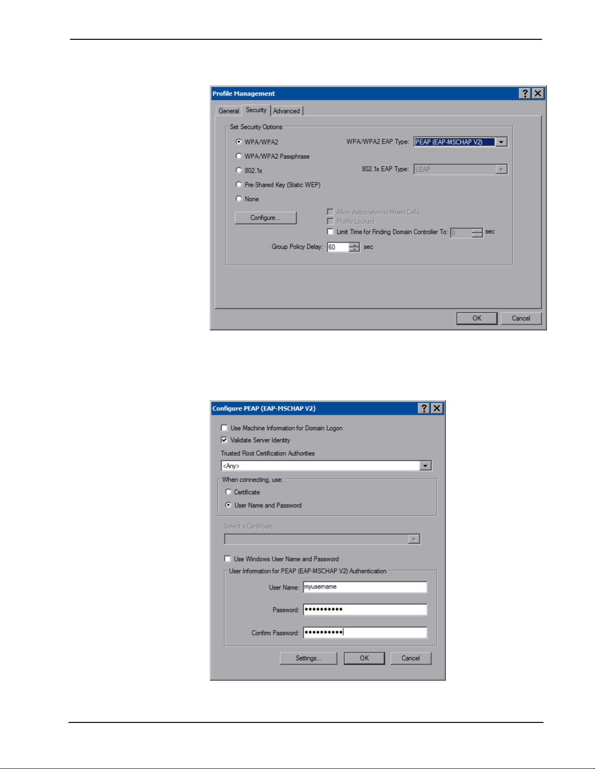
Crestron TPMC-8X Isys i/O™ 8.4” WiFi Touchpanel
“Profile Management” Window (Security)
Select one of the Security Options. Depending on your choice, one of the drop down
boxes to the right, either WPA/WPA2 EAP Type or 802.1x EAP Type, will become
enabled. Use the drop down box to make your selection, then click Configure….
“Configure PEAP” Window
Operations Guide – DOC. 6539B Isys i/O™ 8.4” WiFi Touchpanel: TPMC-8X • 71

Isys i/O™ 8.4” WiFi Touchpanel Crestron TPMC-8X
Selecting Validate Server Identity will enable the Trusted Root Certification
Authorities drop down box.
Selecting Certificate in the When connecting, use: section, will enable the Select a
Certificate drop down box.
Fill in the User Name, Password and Confirm Password boxes, then click
Settings… to open the “Configure Advanced Settings” window.
“Configure Advanced Settings” Window
Enter the Server of Domain Name and Login Name. Then, click OK.
You will be returned to the previous window. Click OK to return to the “Profile
Management” window. Click OK again to return to the “Atheros Client Utility”
window.
With the Profile Management tab selected, the window will display the new entry.
Select the entry within the window and click Activate. To complete the process,
close this window using the “X” in the upper right corner.
72 • Isys i/O™ 8.4” WiFi Touchpanel: TPMC-8X Operations Guide – DOC. 6539B

Crestron TPMC-8X Isys i/O™ 8.4” WiFi Touchpanel
Appendix B: TPMC-8X Security Pack (Intel PROSet)
In some situations, such as when your wireless access point is connected to a
RADIUS (Remote Authentication Dial In User Service) server, authentication is
required before network access is granted.
In order to gain access in this infrastructure, a username and password must be
entered for verification by the server. To facilitate this, the TPMC-8X Security Pack
adds the Intel PROSet Wireless configuration utility.
The Security Pack is available as a special firmware build (TPMC-8X_SP_1.4.zip or
later) for the TPMC-8X. For details on how to upgrade firmware, refer to “Programs,
Projects and Firmware” which starts on page 61.
NOTE: The TPMC-8X Security Pack is only needed if authentication is required by
the server with which your wireless access point communicates. If authentication is
not required, Crestron recommends that you do not install this package. Once
installed it cannot be removed without sending the TPMC-8X back to Crestron.
To begin the authentication process for your wireless access point, click AP in the
“Ethernet Setup” window. (Refer to illustration on page 38.) The “Intel
PROSet/Wireless” window will open, showing the access points within range of the
TPMC-8X.
“Intel® PROSet/Wireless” Window
®
Click Profiles… to open the “Profiles” window.
Operations Guide – DOC. 6539B Isys i/O™ 8.4” WiFi Touchpanel: TPMC-8X • 73

Isys i/O™ 8.4” WiFi Touchpanel Crestron TPMC-8X
“Profiles” Window
Click Add… to open the “Create Wireless Profile” window’s “General Settings”.
“Create Wireless Profile” Window (General Settings)
74 • Isys i/O™ 8.4” WiFi Touchpanel: TPMC-8X Operations Guide – DOC. 6539B

Crestron TPMC-8X Isys i/O™ 8.4” WiFi Touchpanel
Enter a name for the profile in Profile Name and the name of your wireless network
in Wireless Network Name (SSID). Click Next >> to proceed to “Security Settings”.
“Create Wireless Profile” Window (Security Settings – PEAP User)
Use the drop down boxes to select your Network Authentication type, Data
Encryption type, Authentication Type and Authentication Protocol. Make sure the
Enable 802.1x checkbox is checked.
Enter a User Name, Domain and Password. The Roaming Identity should match the
Domain. Then click Next >> to proceed to the second “Security Settings” window.
Operations Guide – DOC. 6539B Isys i/O™ 8.4” WiFi Touchpanel: TPMC-8X • 75

Isys i/O™ 8.4” WiFi Touchpanel Crestron TPMC-8X
“Create Wireless Profile” Window (Security Settings – PEAP Server)
Leave both checkboxes in the Step 2 of 2: PEAP Server part of the window
unchecked, then click OK.
The “Profiles” window will now show your authenticated access point.
“Profiles” Window - Showing Authenticated Access Point
Click Close to complete the process.
®
The “Intel
76 • Isys i/O™ 8.4” WiFi Touchpanel: TPMC-8X Operations Guide – DOC. 6539B
PROSet/Wireless” window will now show the connection.
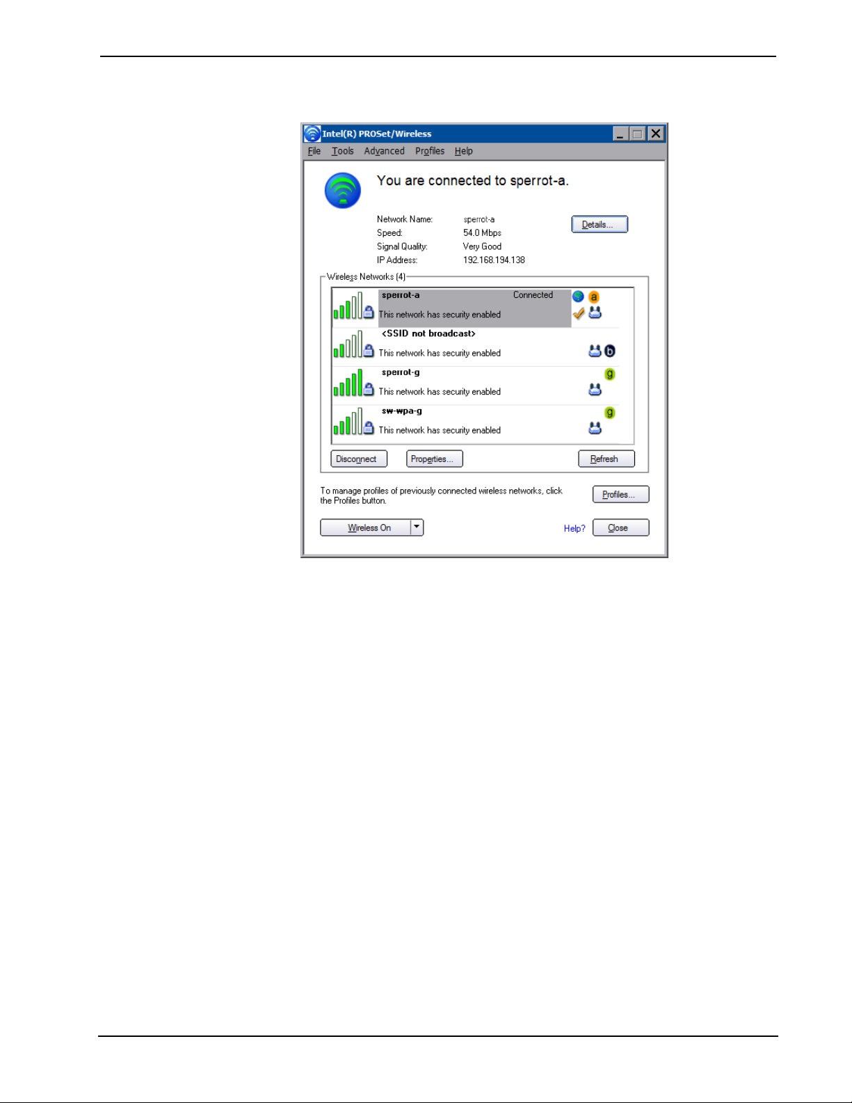
Crestron TPMC-8X Isys i/O™ 8.4” WiFi Touchpanel
“Intel® PROSet/Wireless” Window - Showing Connection
Operations Guide – DOC. 6539B Isys i/O™ 8.4” WiFi Touchpanel: TPMC-8X • 77

Isys i/O™ 8.4” WiFi Touchpanel Crestron TPMC-8X
Appendix C: TPMC-8X Multi-Language Pack
The TPMC-8X Multi-Language Pack adds support for 32 international languages in
addition to the default English language support in the TPMC-8X. This allows the
user to view documents written in those languages by all the embedded apps in the
touchpanel.
The 32 international languages added by the Multi-Language Pack are:
Arabic, Chinese (simplified), Chinese (traditional), Croatian, Czech, Danish, Dutch,
Estonian, Finnish, French, German, Greek, Hebrew, Hungarian, Icelandic,
Indonesian, Italian, Japanese, Korean, Latvian, Lithuanian, Norwegian, Polish,
Portuguese, Romanian, Russian, Serbian, Slovak, Slovenian, Spanish, Swedish and
Turkish.
The Multi-Language Pack is available as a special firmware build
(TPMC-8X_MLP_1.0.zip or later) for the TPMC-8X. For details on how to upgrade
firmware, refer to “Programs, Projects and Firmware” which starts on page 61.
NOTE: Once installed, the TPMC-8X Multi-Language Pack cannot be removed
without sending the TPMC-8X back to Crestron.
78 • Isys i/O™ 8.4” WiFi Touchpanel: TPMC-8X Operations Guide – DOC. 6539B

Crestron TPMC-8X Isys i/O™ 8.4” WiFi Touchpanel
Software License Agreement
This License Agreement (“Agreement”) is a legal contract between you (either an individual or a single business entity) and
Crestron Electronics, Inc. (“Crestron”) for software referenced in this guide, which includes computer software and as applicable,
associated media, printed materials and “online” or electronic documentation (the “Software”).
BY INSTALLING, COPYING OR OTHERWISE USING THE SOFTWARE, YOU REPRESENT THAT YOU ARE AN
AUTHORIZED DEALER OF CRESTRON PRODUCTS OR A CRESTRON AUTHORIZED INDEPENDENT PROGRAMMER
AND YOU AGREE TO BE BOUND BY THE TERMS OF THIS AGREEMENT. IF YOU DO NOT AGREE TO THE TERMS OF
THIS AGREEMENT, DO NOT INSTALL OR USE THE SOFTWARE.
IF YOU HAVE PAID A FEE FOR THIS LICENSE AND DO NOT ACCEPT THE TERMS OF THIS AGREEMENT,
CRESTRON WILL REFUND THE FEE TO YOU PROVIDED YOU (1) CLICK THE DO NOT ACCEPT BUTTON, (2) DO NOT
INSTALL THE SOFTWARE AND (3) RETURN ALL SOFTWARE, MEDIA AND OTHER DOCUMENTATION AND
MATERIALS PROVIDED WITH THE SOFTWARE TO CRESTRON AT: CRESTRON ELECTRONICS, INC., 15 VOLVO
DRIVE, ROCKLEIGH, NEW JERSEY 07647, WITHIN 30 DAYS OF PAYMENT.
LICENSE TERMS
Crestron hereby grants You and You accept a nonexclusive, nontransferable license to use the Software (a) in machine
readable object code together with the related explanatory written materials provided by Crestron (b) on a central processing unit
(“CPU”) owned or leased or otherwise controlled exclusively by You and (c) only as authorized in this Agreement and the related
explanatory files and written materials provided by Crestron.
If this software requires payment for a license, you may make one backup copy of the Software, provided Your backup copy
is not installed or used on any CPU. You may not transfer the rights of this Agreement to a backup copy unless the installed copy of
the Software is destroyed or otherwise inoperable and You transfer all rights in the Software.
You may not transfer the license granted pursuant to this Agreement or assign this Agreement without the express written
consent of Crestron.
If this software requires payment for a license, the total number of CPU’s on which all versions of the Software are installed
may not exceed one per license fee (1) and no concurrent, server or network use of the Software (including any permitted back-up
copies) is permitted, including but not limited to using the Software (a) either directly or through commands, data or instructions from
or to another computer (b) for local, campus or wide area network, internet or web hosting services or (c) pursuant to any rental,
sharing or “service bureau” arrangement.
The Software is designed as a software development and customization tool. As such Crestron cannot and does not
guarantee any results of use of the Software or that the Software will operate error free and You acknowledge that any development
that You perform using the Software or Host Application is done entirely at Your own risk.
The Software is licensed and not sold. Crestron retains ownership of the Software and all copies of the Software and
reserves all rights not expressly granted in writing.
OTHER LIMITATIONS
You must be an Authorized Dealer of Crestron products or a Crestron Authorized Independent Programmer to install or use
the Software. If Your status as a Crestron Authorized Dealer or Crestron Authorized Independent Programmer is terminated, Your
license is also terminated.
You may not rent, lease, lend, sublicense, distribute or otherwise transfer or assign any interest in or to the Software.
You may not reverse engineer, decompile or disassemble the Software.
You agree that the Software will not be shipped, transferred or exported into any country or used in any manner prohibited
by the United States Export Administration Act or any other export laws, restrictions or regulations (“Export Laws”). By downloading
or installing the Software You (a) are certifying that You are not a national of Cuba, Iran, Iraq, Libya, North Korea, Sudan, Syria or
any country to which the United States embargoes goods (b) are certifying that You are not otherwise prohibited from receiving the
Software and (c) You agree to comply with the Export Laws.
If any part of this Agreement is found void and unenforceable, it will not affect the validity of the balance of the Agreement,
which shall remain valid and enforceable according to its terms. This Agreement may only be modified by a writing signed by an
authorized officer of Crestron. Updates may be licensed to You by Crestron with additional or different terms. This is the entire
agreement between Crestron and You relating to the Software and it supersedes any prior representations, discussions, undertakings,
communications or advertising relating to the Software. The failure of either party to enforce any right or take any action in the event
of a breach hereunder shall constitute a waiver unless expressly acknowledged and set forth in writing by the party alleged to have
provided such waiver.
Operations Guide – DOC. 6539B Isys i/O™ 8.4” WiFi Touchpanel: TPMC-8X • 79

Isys i/O™ 8.4” WiFi Touchpanel Crestron TPMC-8X
If You are a business or organization, You agree that upon request from Crestron or its authorized agent, You will within
thirty (30) days fully document and certify that use of any and all Software at the time of the request is in conformity with Your valid
licenses from Crestron of its authorized agent.
Without prejudice to any other rights, Crestron may terminate this Agreement immediately upon notice if you fail to comply
with the terms and conditions of this Agreement. In such event, you must destroy all copies of the Software and all of its component
parts.
PROPRIETARY RIGHTS
Copyright. All title and copyrights in and to the Software (including, without limitation, any images, photographs,
animations, video, audio, music, text and “applets” incorporated into the Software), the accompanying media and printed materials
and any copies of the Software are owned by Crestron or its suppliers. The Software is protected by copyright laws and international
treaty provisions. Therefore, you must treat the Software like any other copyrighted material, subject to the provisions of this
Agreement.
Submissions. Should you decide to transmit to Crestron’s website by any means or by any media any materials or other
information (including, without limitation, ideas, concepts or techniques for new or improved services and products), whether as
information, feedback, data, questions, comments, suggestions or the like, you agree such submissions are unrestricted and shall be
deemed non-confidential and you automatically grant Crestron and its assigns a non-exclusive, royalty-free, worldwide, perpetual,
irrevocable license, with the right to sublicense, to use, copy, transmit, distribute, create derivative works of, display and perform the
same.
Trademarks. CRESTRON and the Swirl Logo are registered trademarks of Crestron Electronics, Inc. You shall not remove
or conceal any trademark or proprietary notice of Crestron from the Software including any back-up copy.
GOVERNING LAW
This Agreement shall be governed by the laws of the State of New Jersey, without regard to conflicts of laws principles.
Any disputes between the parties to the Agreement shall be brought in the state courts in Bergen County, New Jersey or the federal
courts located in the District of New Jersey. The United Nations Convention on Contracts for the International Sale of Goods shall not
apply to this Agreement.
CRESTRON LIMITED WARRANTY
CRESTRON warrants that: (a) the Software will perform substantially in accordance with the published specifications for a
period of ninety (90) days from the date of receipt and (b) that any hardware accompanying the Software will be subject to its own
limited warranty as stated in its accompanying written material. Crestron shall, at its option, repair or replace or refund the license fee
for any Software found defective by Crestron if notified by you within the warranty period. The foregoing remedy shall be your
exclusive remedy for any claim or loss arising from the Software.
CRESTRON shall not be liable to honor warranty terms if the product has been used in any application other than that for
which it was intended or if it as been subjected to misuse, accidental damage, modification or improper installation procedures.
Furthermore, this warranty does not cover any product that has had the serial number or license code altered, defaced, improperly
obtained or removed.
Notwithstanding any agreement to maintain or correct errors or defects, Crestron shall have no obligation to service or
correct any error or defect that is not reproducible by Crestron or is deemed in Crestron’s reasonable discretion to have resulted from
(1) accident; unusual stress; neglect; misuse; failure of electric power, operation of the Software with other media not meeting or not
maintained in accordance with the manufacturer’s specifications or causes other than ordinary use; (2) improper installation by anyone
other than Crestron or its authorized agents of the Software that deviates from any operating procedures established by Crestron in the
material and files provided to You by Crestron or its authorized agent; (3) use of the Software on unauthorized hardware or (4)
modification of, alteration of or additions to the Software undertaken by persons other than Crestron or Crestron’s authorized agents.
ANY LIABILITY OF CRESTRON FOR A DEFECTIVE COPY OF THE SOFTWARE WILL BE LIMITED
EXCLUSIVELY TO REPAIR OR REPLACEMENT OF YOUR COPY OF THE SOFTWARE WITH ANOTHER COPY OR
REFUND OF THE INITIAL LICENSE FEE CRESTRON RECEIVED FROM YOU FOR THE DEFECTIVE COPY OF THE
PRODUCT. THIS WARRANTY SHALL BE THE SOLE AND EXCLUSIVE REMEDY TO YOU. IN NO EVENT SHALL
CRESTRON BE LIABLE FOR INCIDENTAL, CONSEQUENTIAL, SPECIAL OR PUNITIVE DAMAGES OF ANY KIND
(PROPERTY OR ECONOMIC DAMAGES INCLUSIVE), EVEN IF A CRESTRON REPRESENTATIVE HAS BEEN ADVISED
OF THE POSSIBILITY OF SUCH DAMAGES OR OF ANY CLAIM BY ANY THIRD PARTY. CRESTRON MAKES NO
WARRANTIES, EXPRESS OR IMPLIED, AS TO TITLE OR INFRINGEMENT OF THIRD-PARTY RIGHTS,
MERCHANTABILITY OR FITNESS FOR ANY PARTICULAR PURPOSE, OR ANY OTHER WARRANTIES, NOR
AUTHORIZES ANY OTHER PARTY TO OFFER ANY WARRANTIES, INCLUDING WARRANTIES OF
MERCHANTABILITY FOR THIS PRODUCT. THIS WARRANTY STATEMENT SUPERSEDES ALL PREVIOUS
WARRANTIES.
80 • Isys i/O™ 8.4” WiFi Touchpanel: TPMC-8X Operations Guide – DOC. 6539B

Crestron TPMC-8X Isys i/O™ 8.4” WiFi Touchpanel
Return and Warranty Policies
Merchandise Returns / Repair Service
1. No merchandise may be returned for credit, exchange or service without prior authorization
from CRESTRON. To obtain warranty service for CRESTRON products, contact an
authorized CRESTRON dealer. Only authorized CRESTRON dealers may contact the factory
and request an RMA (Return Merchandise Authorization) number. Enclose a note specifying
the nature of the problem, name and phone number of contact person, RMA number and
return address.
2. Products may be returned for credit, exchange or service with a CRESTRON Return
Merchandise Authorization (RMA) number. Authorized returns must be shipped freight
prepaid to CRESTRON, 6 Volvo Drive, Rockleigh, N.J. or its authorized subsidiaries, with
RMA number clearly marked on the outside of all cartons. Shipments arriving freight collect
or without an RMA number shall be subject to refusal. CRESTRON reserves the right in its
sole and absolute discretion to charge a 15% restocking fee plus shipping costs on any
products returned with an RMA.
3. Return freight charges following repair of items under warranty shall be paid by CRESTRON,
shipping by standard ground carrier. In the event repairs are found to be non-warranty, return
freight costs shall be paid by the purchaser.
CRESTRON Limited Warranty
CRESTRON ELECTRONICS, Inc. warrants its products to be free from manufacturing defects in materials
and workmanship under normal use for a period of three (3) years from the date of purchase from
CRESTRON, with the following exceptions: disk drives and any other moving or rotating mechanical
parts, pan/tilt heads and power supplies are covered for a period of one (1) year; touchscreen display and
overlay components are covered for 90 days; batteries and incandescent lamps are not covered.
This warranty extends to products purchased directly from CRESTRON or an authorized CRESTRON
dealer. Purchasers should inquire of the dealer regarding the nature and extent of the dealer's warranty, if
any.
CRESTRON shall not be liable to honor the terms of this warranty if the product has been used in any
application other than that for which it was intended or if it has been subjected to misuse, accidental
damage, modification or improper installation procedures. Furthermore, this warranty does not cover any
product that has had the serial number altered, defaced or removed.
This warranty shall be the sole and exclusive remedy to the original purchaser. In no event shall
CRESTRON be liable for incidental or consequential damages of any kind (property or economic damages
inclusive) arising from the sale or use of this equipment. CRESTRON is not liable for any claim made by a
third party or made by the purchaser for a third party.
CRESTRON shall, at its option, repair or replace any product found defective, without charge for parts or
labor. Repaired or replaced equipment and parts supplied under this warranty shall be covered only by the
unexpired portion of the warranty.
Except as expressly set forth in this warranty, CRESTRON makes no other warranties, expressed or
implied, nor authorizes any other party to offer any warranty, including any implied warranties of
merchantability or fitness for a particular purpose. Any implied warranties that may be imposed by law are
limited to the terms of this limited warranty. This warranty statement supersedes all previous warranties.
Trademark Information
All brand names, product names and trademarks are the sole property of their respective owners. Windows is a registered trademark
of Microsoft Corporation. Windows95/98/Me/XP/Vista and WindowsNT/2000 are trademarks of Microsoft Corporation.
Operations Guide – DOC. 6539B Isys i/O™ 8.4” WiFi Touchpanel: TPMC-8X • 81

Isys i/O™ 8.4” WiFi Touchpanel Crestron TPMC-8X
Microsoft® Windows XP® Embedded End User License Agreement
• You have acquired a device (“DEVICE”) that includes software licensed by Crestron Electronics from Microsoft Licensing
Inc. or its affiliates (“MS”). Those installed software products of MS origin, as well as associated media, printed materials,
and “online” or electronic documentation (“SOFTWARE”), are protected by international intellectual property laws and
treaties. The SOFTWARE is licensed, not sold. All rights reserved.
• IF YOU DO NOT AGREE TO THIS END USER LICENSE AGREEMENT (“EULA”), DO NOT USE THE DEVICE OR
COPY THE SOFTWARE. INSTEAD, PROMPTLY CONTACT CRESTRON ELECTRONICS FOR INSTRUCTIONS ON
RETURN OF THE UNUSED DEVICE(S) FOR A REFUND. ANY USE OF THE SOFTWARE, INCLUDING BUT
NOT LIMITED TO USE ON THE DEVICE, WILL CONSTITUTE YOUR AGREEMENT TO THIS EULA (OR
RATIFICATION OF ANY PREVIOUS CONSENT).
• GRANT OF SOFTWARE LICENSE. This EULA grants you the following license:
o You may use the SOFTWARE only on the DEVICE.
o NOT FAULT TOLERANT. THE SOFTWARE IS NOT FAULT TOLERANT. CRESTRON ELECTRONICS
HAS INDEPENDENTLY DETERMINED HOW TO USE THE SOFTWARE IN THE DEVICE, AND MS HAS
RELIED UPON CRESTRON ELECTRONICS TO CONDUCT SUFFICIENT TESTING TO DETERMINE THAT
THE SOFTWARE IS SUITABLE FOR SUCH USE.
o NO WARRANTIES FOR THE SOFTWARE. THE SOFTWARE IS PROVIDED “AS IS” AND WITH ALL
FAULTS. THE ENTIRE RISK AS TO SATISFACTORY QUALITY, PERFORMANCE, ACCURACY, AND
EFFORT (INCLUDING LACK OF NEGLIGENCE) IS WITH YOU. ALSO, THERE IS NO WARRANTY
AGAINST INTERFERENCE WITH YOUR ENJOYMENT OF THE SOFTWARE OR AGAINST
INFRINGEMENT. IF YOU HAVE RECEIVED ANY WARRANTIES REGARDING THE DEVICE OR THE
SOFTWARE, THOSE WARRANTIES DO NOT ORIGINATE FROM, AND ARE NOT BINDING ON, MS.
o No Liability for Certain Damages. EXCEPT AS PROBHIBITED BY LAW, MS SHALL HAVE NO
LIABILITY FOR ANY INDIRECT, SPECIAL, CONSEQUENTIAL OR INCIDENTAL DAMAGES ARISING
FROM OR IN CONNECTION WITH THE USE OR PERFORMANCE OF THE SOFTWARE. THIS
LIMITATION SHALL APPLY EVEN IF ANY REMEDY FAILS OF ITS ESSENTIAL PURPOSE. IN NO
EVEN SHALL MS BE LIABLE FOR ANY AMOUNT IN EXCESS OF U.S. TWO HUNDRED FIFTY
DOLLARS (U.S. $250.00).
o Limitations on Reverse Engineering, Decompilation, and Disassembly. You may not reverse engineer,
decompile, or disassemble the SOFTWARE, except and only to the extent that such activity is expressly permitted by
applicable law notwithstanding this limitation.
o SOFTWARE TRANSFER ALLOWED BUT WITH RESTRICTIONS. You may permanently transfer rights
under this EULA only as part of a permanent sale or transfer of the Device, and only if the recipient agrees to this
EULA. If the SOFTWARE is an upgrade, any transfer must also include all prior versions of the SOFTWARE.
o EXPORT RESTRICTIONS. You acknowledge that SOFTWARE is subject to U.S. export jurisdiction. You
agree to comply with all applicable international and national laws that apply to the SOFTWARE, including the U.S.
Export Administration Regulations, as well as end-user, end-use and destination restrictions issued by U.S. and other
governments. For additional information, see www.microsoft.com/exporting
• Limited Use of Particular SOFTWARE Services. Provided that the DEVICE continues to comply with the terms of the
“Restricted Functionality” paragraph below, without limiting the number of computers or other electronic devices that might
connect to the DEVICE to access or utilize other software or SOFTWARE services on the DEVICE, you may permit a
maximum of ten (10) computers or other electronic devices to connect to the DEVICE to utilize the services of the
SOFTWARE for (a) file and print services, (b) Internet information services, and/or (c) remote access (including connection
sharing). The ten (10) connections maximum includes any indirect connections made through “multiplexing” or other
software or hardware which pools or aggregates connections.
• If you use the DEVICE to access or utilize the services or functionality of Microsoft Windows Server products (such as
Microsoft Windows NT Server 4.0 (all editions) or Microsoft Windows 2000 Server (all editions)), or use the DEVICE to
permit workstation or computing devices to access or utilize the services or functionality of Microsoft Windows Server
products, you may be required to obtain a Client Access License for the DEVICE and/or each such workstation or
computing device. Please refer to the End-User License Agreement for your Microsoft Windows Server product for
additional information.
• Restricted Deployment. The SOFTWARE is not designed or intended for use or resale in hazardous environments
requiring fail-safe performance, such as in the operation of nuclear facilities, aircraft navigation or communication systems,
air traffic control, or other devices or systems in which a malfunction of the SOFTWARE would result in foreseeable risk of
injury or death to the operator of the device or system, or to others.
• Restricted Functionality. You are licensed to use the SOFTWARE to provide only the limited functionality (specific tasks
or processes) for which the DEVICE has been designed and marketed by Crestron. This license specifically prohibits any
other use of the SOFTWARE, or inclusion of additional software programs or functions, on the DEVICE. Subject to the
terms of the “Limited Use of Particular Services” paragraph above, you may use the SOFTWARE on the DEVICE to
interact with other computers or electronic devices.
.
82 • Isys i/O™ 8.4” WiFi Touchpanel: TPMC-8X Operations Guide – DOC. 6539B

Crestron TPMC-8X Isys i/O™ 8.4” WiFi Touchpanel
• Maximum Number of Processors. The SOFTWARE may not be used by more than two (2) processors at any one time on
the DEVICE.
• Remote Boot Feature. Your DEVICE may be enabled with a Remote Boot feature which includes Remote Boot Installation
Services tool. You may use the Remote Boot Installation Services tool only to deploy the SOFTWARE to one or more
DEVICEs on which you are licensed to run the SOFTWARE (i.e. DEVICEs to which the appropriate Certificate of
Authenticity is affixed). Please refer to the DEVICE documentation, if provided with your DEVICE, or contact Crestron for
additional information.
• Security Updates. Content providers are using the digital rights management technology (“Microsoft DRM”) contained in
this SOFTWARE to protect the integrity of their content (“Secure Content”) so that their intellectual property, including
copyright, in such content is not misappropriated. Owners of such Secure Content (“Secure Content Owners”) may, from
time to time, request MS, Microsoft Corporation, or their subsidiaries to provide security related updates to the Microsoft
DRM components of the SOFTWARE (“Security Updates”) that may affect your ability to copy, display, and/or play Secure
Content through Microsoft software or third-party applications that utilize Microsoft DRM. You therefore agree that, if you
elect to download a license from the Internet, which enables our use of Secure Content, MS, Microsoft Corporation, or their
subsidiaries may, in conjunction with such license, also download onto your DEVICE such Security Updates that a Secure
Content Owner has requested that MS, Microsoft Corporation, or their subsidiaries distribute. MS, Microsoft Corporation, or
their subsidiaries will not retrieve any personally identifiable information, or any other information, from your DEVICE by
downloading such Security Updates.
• NetMeeting/Remote Assistance/Remote Desktop Features. The SOFTWARE may contain NetMeeting, Remote
Assistance, and Remote Desktop technologies that enable the SOFTWARE or other applications installed on the Device to
be used remotely between two or more computing devices, even if the SOFTWARE or application is installed on only one
Device. You may use NetMeeting, Remote Assistance, and Remote Desktop with all Microsoft products; provided,
however, use of these technologies with certain Microsoft products may require an additional license. For both Microsoft
products and non-Microsoft products, you should consult the license agreement accompanying the applicable product or
contact the applicable licensor to determine whether use of NetMeeting, Remote Assistance, or Remote Desktop is permitted
without an additional license.
• Consent to Use of Data. You agree that MS, Microsoft Corporation, and their affiliates may collect and use technical
information gathered in any manner as part of product support services related to the SOFTWARE. MS, Microsoft
Corporation, and their affiliates may use this information solely to improve their products or to provide customized services
or technologies to you. MS, Microsoft Corporation, and their affiliates may disclose this information to others, but not in a
form that personally identifies you.
• Internet Gaming/Update Features. If the SOFTWARE provides, and you choose to utilize, the Internet gaming or update
features within the SOFTWARE, it is necessary to use certain computer system, hardware, and software information to
implement the features. By using these features, you explicitly authorize MS, Microsoft Corporation, and/or their designated
agent to use this information solely to improve their products or to provide customized services or technologies to you. MS
or Microsoft Corporation may disclose this information to others, but not in a form that personally identifies you.
• Internet –Based Services Components. The SOFTWARE may contain components that enable and facilitate the use of
certain Internet-based services. You acknowledge and agree that MS, Microsoft Corporation, or their affiliates may
automatically check the version of the SOFTWARE and/or its components that you are utilizing and may provide upgrades
or supplements to the SOFTWARE that may be automatically downloaded to your Device.
• Links to Third-Party Sites. The SOFTWARE may provide you with the ability to link to third-party sites through the use
of the SOFTWARE. The third-party sites are not under the control of MS, Microsoft Corporation, or their affiliates. Neither
MS nor Microsoft Corporation nor their affiliates are responsible for (i) the contents of any third-party sites, any links
contained in third-party sites, or any changes or updates to third-party sites, or (ii) webcasting or any other form of
transmission received from any third-party sites. If the SOFTWARE provides links to third-party sites, those links are
provided to you only as a convenience, and the inclusion of any link does not imply an endorsement of the third-party site
by MS, Microsoft Corporation, or their affiliates.
• Additional Software/Services. The SOFTWARE may permit Crestron, MS, Microsoft Corporation, or their affiliates to
provide or make available to you SOFTWARE updates, supplements, add-on components, or Internet-based services
components of the SOFTWARE after the date you obtain your initial copy of the SOFTWARE (“Supplemental
Components”).
o If Crestron provides or makes available to you Supplemental Components and no other EULA terms are provided
along with the Supplemental Components, then the terms of this EULA shall apply.
o If MS, Microsoft Corporation, or their affiliates make available Supplemental Components, and no other EULA
terms are provided, then the terms of this EULA shall apply, except that the MS, Microsoft Corporation, or affiliate
entity providing the Supplemental Components(s) shall be the licensor of the Supplemental Component(s).
Crestron, MS, Microsoft Corporation, and their affiliates reserve the right to discontinue any Internet-based
services provided to you or made available to you through the use of the SOFTWARE.
This EULA does not grant you any rights to use the Windows Media Format Software Development Kit (“WMFSDK”)
components contained in the SOFTWARE to develop a software application that uses Windows Media technology. If you wish
to use the WMFSDK to develop such an application, visit htt://msdn.Microsoft.com/workshop/imedia/windowsmedia/sdk/
wmsdk.asp, accept a separate license for the WMFSDK, download the appropriate WMFSDK, and install it on your system.
Operations Guide – DOC. 6539B Isys i/O™ 8.4” WiFi Touchpanel: TPMC-8X • 83

Crestron Electronics, Inc. Operations Guide – DOC. 6539B
15 Volvo Drive Rockleigh, NJ 07647 (2016825)
Tel: 888.CRESTRON 01.08
Fax: 201.767.7576 Specifications subject to
www.crestron.com change without notice.
 Loading...