

Page 1

Crestron CAT5 Wiring
Reference Guide
Page 2

This document was prepared and written by the Technical Documentation department at:
Crestron Electronics, Inc.
15 Volvo Drive
Rockleigh, NJ 07647
1-888-CRESTRON
All brand names, product names and trademarks are the property of their respective owners.
©2004 Crestron Electronics, Inc.
Page 3

Crestron CAT5 Wiring Reference Guide
Contents
Crestron CAT5 Wiring 1
Introduction ...............................................................................................................................1
Electrical Measurements of CAT5E Wiring..............................................................................2
Installation Notes.......................................................................................................................2
CAT5 Pin and Color Specifications...........................................................................................3
CAT5 Cable Pairs.............................................................................................................3
CAT5 Wiring EIA Specification TIA-568B.....................................................................4
CAT5 Wiring EIA Specification TIA-568A.....................................................................4
Audio Applications....................................................................................................................5
CNXRMCLV Balanced Audio Connector .......................................................................5
CNX-BIPAD8 Balanced Audio Connector ......................................................................5
TPS-IMC-BV Balanced Audio Connector .......................................................................6
TPS-IMPC Balanced Audio Connector............................................................................6
TPS-IMW Audio Connector.............................................................................................6
TPS-2000L Balanced Audio Connector ...........................................................................7
TPS-3000L/3100L/4000L Balanced Audio Connector.....................................................7
TPS-3000L/TPS-3100L/4000L Unbalanced Audio Connector........................................7
C2N-DAP8 and C2N-DAP8RC Balanced Audio Connector ...........................................8
C2N-TXM Audio Out Connector.....................................................................................8
Balanced Audio Cable from CNXRMCLV to TPS-IMC, TPS-IMC-BV, & TPS-IMW.9
Mic Cable Wiring from TPS-IMC, TPS-IMC-BV, & TPS-IMW to CNXRMCLV.......10
Balanced Audio Connection from CNX-BIPAD8 to TPS-2000L..................................11
Balanced Audio Connections from TPS-IMC-BV to CNX-BIPAD8 (Mic and Audio).12
Audio from C2N-DAP8RC to CNXRMCLV.................................................................13
Audio from CNXRMCLV to C2N-DAP8......................................................................14
Audio from CNX-BIPAD8 to C2N-DAP8.....................................................................15
Audio and Mic Connections from TPS-IMC-BV to CNXRMCLV................................16
Audio and Mic Connections to Touchpanel Direct from CNXRMCLV ........................17
Audio Output from C2N-TXM to CNX-BIPAD8..........................................................17
Balanced and Unbalanced Audio and Video Applications......................................................18
Balanced Audio and Balanced Video from CNXRMCLV to TPS-2000L...................... 18
Unbalanced Audio Input, Video Input, and MIC Output for a TPS-2000L....................20
Balanced Video Applications ..................................................................................................21
CNXRMCLV Balanced Input and Output Video Connectors........................................21
CNX-PVID8 Balanced Video Connector.......................................................................21
TPS-IMW NET/Video Connector..................................................................................22
TPS-IMC-BV Balanced Video Connector......................................................................22
TPS-2000L Video and Audio Connector........................................................................22
TPS-3000L/TPS-3100L/4000L NTSC/PAL Balanced Video Input Connector .............23
CNXRMC Balanced Video Input Connector..................................................................23
Balanced Video From CNX-PVID8 to C2N-DAP8RC..................................................24
Balanced Video From C2N-DAP8RC to CNX-PBVR4.................................................25
Balanced Composite Video from CNX-PVID to TPS-2000L.......................................26
Reference Guide – DOC. 6137A Contents • i
Page 4

Reference Guide Crestron CAT5 Wiring
Balanced Composite Video from CNX-PVID to TPS-IMC-BV ...................................27
Balanced S-Video from CNX-PVID to TPS-IMC-BV...................................................28
C2N-TFM and C2N-TTVFM AM Radio Port.........................................................................29
C2N-TAMWX AM/Weather Band Tuner...............................................................................29
C2N-IIF Intercom Interface.....................................................................................................30
Audio Connections from C2N-IIF to C2N-IADS30X24 Intercom Audio Distribution
System.............................................................................................................................31
Video Connections from C2N-IIF to C2N-IVDS24X24 Intercom Video Distribution
System.............................................................................................................................32
Video Connections from C2N-IIF to CNX-PBVR4 Professional Balanced Video
Receiver..........................................................................................................................33
Audio Connections from C2N-IIF to CNX-PBAR4 Professional Balanced Audio
Receiver..........................................................................................................................34
C2N-IVDS24X24 Intercom Video Distribution System .........................................................35
C2N-IVDS Video to TPS-IMC-BV Touchpanel Interface.............................................36
C2N-IADS30x24 Intercom Audio Distribution System..........................................................37
C2N-IADS Audio to TPS-IMC-BV Touchpanel Interface.............................................38
C2N-IADS Audio to CNX-BIPAD8 Audio Distribution Processor...............................39
C2N-NPA8 Poll Accelerator LAN Connector.........................................................................40
The QuickMedia Transport System.........................................................................................40
Crestron Certified Wire and Cable...........................................................................................43
Further Inquiries ......................................................................................................................45
Glossary...................................................................................................................................46
References................................................................................................................................47
ii • Contents Crestron CAT5 Wiring - DOC. 6137A
Page 5

Crestron CAT5 Wiring Reference Guide
Crestron CAT5 Wiring
Introduction
Category 5 (CAT5) wiring is a twisted pair cable designed for Ethernet networks.
These networks operate at speeds of up to 100 Megabits per second (Mbps) using the
100baseT standard. Crestron® takes advantage of this specification for a variety of
audio and video applications. This document contains basic CAT5 information and
specific wiring connections for Crestron audio and video CAT5 devices.
The term “Category” refers to the classifications of UTP (unshielded twisted pair)
cables. The differences in the classification of the cables are their electrical
performance criteria. ANSI/EIA (American National Standards Institute/Electronic
Industries Association) Standard 568 is one of several standards that specify these
categories of twisted pair cabling systems, which includes wires, junctions, cable
material and connectors, in terms of the data rates that they can sustain. There are
currently three main Categories of cable - Category 3, Category 4, and Category 5.
• Category 3 = Rated to 16 MHz (used for Ethernet 10BaseT)
• Category 4 = Rated to 20 MHz (used for Token-Ring, 10BaseT)
• Category 5 = Rated to 100 MHz (used for 100BaseT , 10 B a seT)
Under the 10BaseT/100BaseT (twisted pair) standard, the distance between
connected components cannot exceed 328 feet (100 meters).
In large Ethernet configurations, Crestron recommends the use of a hub or switch for
signal distribution. Generally, in a hub system every device must have a separate
wire returning to a central point.
CAT5 wire is typically four pairs of 24AWG solid copper wires, with each pair
twisted about three times per inch. It can be supplied with or without a foil shield,
and with various outer insulation materials.
CAT5E (enhanced) is essentially the same as CAT5, however it is made to higher
electrical standards.
NOTE: Special plenum cable is required if you are running the wire in heating
system plenums or in certain commercial settings.
Reference Guide – DOC. 6137A Crestron CAT5 Wiring • 1
Page 6

Reference Guide Crestron CAT5 Wiring
Electrical Measurements of CAT5E Wiring
The specifications for CAT5E wiring can vary within a range as specified by
TIA/EIA. These specifications depend on the kind of connections (permanent,
patchcords, etc.), the length of cable run, and the type of termination connectors. The
following are a list of measurements that are made on CAT5E cables.
• Attenuation is a measure of signal loss from one end of a cable to the
other, and is measured in each pair of wires.
• NEXT (Near End Cross Talk) is a measurement of noise that is coupled
from an adjacent pair of wires, usually the receiving pair and the
transmitting pair. NEXT is measured for all pair combinations.
• PSNEXT (Power Sum NEXT) is the measurement of one pair while all the
other pairs are in use. This calculation is made for each pair in the cable.
• Delay Skew (Propagation Delay) is the measurement of signal speed
through the wires. All the wires of the cable are fed the same signal
simultaneously. The time difference at the receiving end of each wire is
measured, and the shortest time is subtracted from the longest time.
Installation Notes
• FEXT (Far End Cross Talk) is measured by transmitting on one pair and
measuring cross talk on an adjacent pair at the far end of the cable.
• ELFEXT (Equal Level Far End Cross Talk) is FEXT minus Attenuation.
• PSELFEXT (Power Sum ELFEXT) uses all wires in the cable.
• ACR (Attenuation to Cross Talk Ratio) is a measurement of the ratio of
signal to noise and reveals the bandwidth of the cable. It is derived by the
difference between NEXT and Attenuation.
• Never pull CAT5 wire with excessive force. The CAT5 tension limitation is
25 lbs, much lower than standard audio/video cable.
• Never step on or crush, kink, or crimp CAT5.
• Avoid periodic sags; vary the intervals if the cable must sag.
• Do not bend CAT5 wire tightly around a corner; ensure that it bends
gradually, so that a whole circle would be at least two inches in diameter.
• Do not allow knots or kinks, even temporarily.
• When using conduit, do not fill to more than 40% if using more than two
cables (National Electrical Code, Chapter 9, Table 1).
• Never untwist the two wires in a single pair for more than 1/3-1/2"
(0.84 – 1.27 cm) when making a connection (the twists are critical to
canceling out interference between the wires).
• Never run CAT5 parallel to power wiring closer than six inches.
• Avoid splices. Every splice degrades the line.
2 • Crestron CAT5 Wiring Reference Guide - DOC. 6137A
Page 7

Crestron CAT5 Wiring Reference Guide
CAT5 Pin and Color Specifications
There are two standards for CAT5 wiring, TIA-568B and TIA-568A.
TIA-568B is a straight-through connection. The signals on pins 1 through 8 are
identical on both ends of the cable.
TIA-568A is a straight-through connection. The signals on pins 1 through 8 are
identical on both ends of the cable. However, the orange and green pairs of wires
exchange pair numbers and are connected to different pins than TIA-568B.
NOTE: To determine which pin is number 1, hold the cable so that the end of the
eight pin modular plug is facing toward you, with clip down and copper side up.
When looking down at the copper connections, pin 1 will be on the far right.
NOTE: Do not confuse pair numbers with pin numbers. A pair number is used for
reference only (e.g., 10BaseT Ethernet uses pairs 2 & 3). The pin numbers indicate
actual physical locations on the plug and jack.
RJ-45 Jack
RJ-45 Plug
1 2 3 4 5 6 7 8
8 7 6 5 4 3 2 1
CAT5 Cable Pairs
The CAT5 twisted cable pairs are color-coded; the pair colors depend on which EIA
specification is used, TIA-568B or TIA-568A.
CAT5 Pair Color Coding
PAIR # SPECIFICATION
TIA-568B
White/Blue White/Blue Pair 1
Blue Blue
White/Orange White/Green Pair 2
Orange Green
White/Green White/Orange Pair 3
Green Orange
Pair 4
White/Brown White/Brown
Brown Brown
SPECIFICATION
TIA-568A
NOTE: Because of their identical pair groupings, cables terminated with either
T568A or T568B pair assignments may be used interchangeably, provided that both
ends are terminated with the same pin/pair scheme.
Reference Guide – DOC. 6137A Crestron CAT5 Wiring • 3
Page 8

Reference Guide Crestron CAT5 Wiring
CAT5 Wiring EIA Specification TIA-568B
Crestron standard CAT5 cable color/pin arrangement is EIA specification TIA-568B,
with identical pin assignments on both ends of the cable.
RJ-45 Jack Pinouts – Standard 568B
PAIR # COLOR PIN #
White/Blue 5 1
Blue 4
White/Orange 1 2
Orange 2
White/Green 3 3
Green 6
White/Brown 7 4
Brown 8
Pin 1
White/Orange
CAT5 Wiring EIA Specification TIA-568A
In the EIA specification TIA-568A CAT5 cable color/pin arrangement, the pairs
remain the same, but the pin number assignment for the orange and green pairs
change.
RJ-45 Jack Pinouts – Standard 568A
PAIR # COLOR PIN #
1 White/ Blue 5
Blue 4
2 White/Green 1
Green 2
3 White/ Orange 3
Orange 6
4 White/Brown 7
Brown 8
Pin 1
White/Green
4 • Crestron CAT5 Wiring Reference Guide - DOC. 6137A
Page 9

Crestron CAT5 Wiring Reference Guide
Audio Applications
NOTE: Balanced audio does not require a shield if the cable has good common
mode characteristics (such as CAT5). Unbalanced audio signals are sent on a single
wire, using ground as the reference for the signal. Ground wires are problematic
because they can carry current when exposed to electromagnetic fields or when there
is a voltage difference between the two connecting pieces of equipment. Balanced
audio uses two signal wires. The signal and its complement are sent down the
twisted pair together. Any noise picked up t ends to be of equal amplitude and in
phase on both wires. At the receiver, the two signals are subtracted, and noise is
cancelled out. This technique is called common mode rejection.
CNXRMCLV Balanced Audio Connector
CNXRMCLV RJ-45 Connector Pinout (AUDIO)
PIN # SIGNAL
1 Audio out L +
2 Audio out L 3 Audio out R +
4 Audio In L +
5 Audio In L 6 Audio out R 7 Audio In R +
8 Audio In R -
1 2 3 4 5 6 7 8
CNX-BIPAD8 Balanced Audio Connector
CNX-BIPAD8 RJ-45 Connector Pinout (ROOMS 1 – 8)
PIN # SIGNAL
1 Audio In L +
2 Audio In L 3 Audio In R +
4 Audio Out L +
5 Audio Out L 6 Audio In R 7 Audio Out R +
8 Audio Out R -
1 2 3 4 5 6 7 8
Reference Guide – DOC. 6137A Crestron CAT5 Wiring • 5
Page 10

Reference Guide Crestron CAT5 Wiring
TPS-IMC-BV Balanced Audio Connector
TPS-IMC-BV RJ-45 Connector Pinout (AUDIO INPUT)
PIN # SIGNAL
1 Mic out +
2 Mic out 3 Mic out +
4 Audio In L +
5 Audio In L 6 Mic out 7 Audio In R +
8 Audio In R -
1 2 3 4 5 6 7 8
TPS-IMPC Balanced Audio Connector
This 8-pin RJ-45 mates with the TPS-3000, TPS-5000, or TPS-6000 touchpanel. The
8-pin audio cable assembly is supplied. Even though the 10-pin net/video cable may
fit into the port, do not use it. This port provides audio input to the touchpanel and
microphone output from the touchpanel .
TPS-IMPC RJ-45 Connector Pinout (AUDIO)
PIN # SIGNAL
1 Left In +
2 Left In 3 GND/Shield
4 Right In +
5 Right In 6 GND/Shield
7 Mic Out +
8 Mic Out -
1 2 3 4 5 6 7 8
TPS-IMW Audio Connector
PIN # SIGNAL
1 Audio Shield
2 Audio Left +
3 Audio Left 4 Audio Right +
5 Audio Right 6
7 Mic Out +
8 Mic Out -
Mic Out
Shield
6 • Crestron CAT5 Wiring Reference Guide - DOC. 6137A
1 2 3 4 5 6 7 8
Page 11

Crestron CAT5 Wiring Reference Guide
TPS-2000L Balanced Audio Connector
TPS-2000L Mini 8-pin Connector Pinout (Mono Audio)
PIN # SIGNAL
1 Audio In +
2 Audio In 3 Ground/Shield
4 Mic Out +
5 Mic Out 6 Ground/Shield
7 Video In +
8 Video In -
1 2 3 4 5 6 7 8
TPS-3000L/3100L/4000L Balanced Audio Connector
PIN # SIGNAL
1 Shield (S)
2 Right In (+)
3 Right In (-)
4 Left In (+)
5 Left In (-)
6 Shield (S)
1 2 3 4 5 6
TPS-3000L/TPS-3100L/4000L Unbalanced Audio Connector
PIN # SIGNAL
1 Ground (S)
2 Right Input (R+)
3 Right Ground (R-)
4 Left Input (L+)
5 Left Ground (L-)
6 Ground (S)
NOTE: Use two jumpers and connect Right Ground (pin 3) to Right Shield (pin 1),
and connect Left Ground (pin 5) to Left Shield (pin 6) at the TPS-3000L Audio Input
connector.
+ - + -
S R R L L S
1 2 3 4 5 6
Reference Guide – DOC. 6137A Crestron CAT5 Wiring • 7
Page 12

Reference Guide Crestron CAT5 Wiring
C2N-DAP8 and C2N-DAP8RC Balanced Audio Connector
C2N-DAP8RC RJ-45 Audio Connector
PIN # SIGNAL
1 Left Audio Out +
2 Left Audio Out 3 Right Audio Out +
4 Right Audio Out 5 Left Audio In +
6 Left Audio In 7 Right Audio In +
8 Right Audio In -
1 2 3 4 5 6 7 8
C2N-TXM Audio Out Connector
C2N-TXM AUDIO OUT Pinout
PIN # SIGNAL
1 Left Audio Out +
2 Left Audio Out 3 Right Audio Out +
4 Not Connected
5 Not Connected
6 Right Audio Out +
7 Not Connected
8 Not Connected
1 2 3 4 5 6 7 8
8 • Crestron CAT5 Wiring Reference Guide - DOC. 6137A
Page 13

Crestron CAT5 Wiring Reference Guide
Balanced Audio Cable from CNXRMCLV to TPS-IMC, TPS-IMC-BV, & TPS-IMW
Audio Cable Connections From CNXRMCLV RJ-45 Connector (AUDIO) to TPS-IMC,
TPS-IMC-BV and TPS-IMW Mini Connector (AUDIO INPUT)
FROM
PIN #
CNXRMCLV
(AUDIO)
RJ-45 CONNECTOR
TO
PIN #
TPS-IMC, TPS-IMC-BV
AND TPS-IMW
(AUDIO INPUT)
MINI CONNECTOR
3 Audio Out R + 2 Audio In R +
6 Audio Out R - 3 Audio In R 1 Audio Out L + 4 Audio In L +
2 Audio Out L - 5 Audio In L -
1 2 3 4 5 6 7 8
Pin 1
1 2 3 4 5 6
1 2 3 4 5 6
Reference Guide – DOC. 6137A Crestron CAT5 Wiring • 9
Page 14

Reference Guide Crestron CAT5 Wiring
Mic Cable Wiring from TPS-IMC, TPS-IMC-BV, & TPS-IMW to CNXRMCLV
TPS-IMC, TPS-IMC-BV and TPS-IMW Mini Connector (MIC OUT) to
CNXRMCLV RJ-45 Connector (AUDIO)
FROM
PIN #
1 Mic Out + 4 Audio In +
2 Mic Out - 5 Audio In 3 Shield Not Connected Not Connected
TPS-IMC, TPS-IMC-
BV AND TPS-IMW
(MIC OUT)
MINI CONNECTOR
1 2 3
TO PIN # CNXRMCLV
(AUDIO)
RJ-45 CONNECTOR
1 2 3 4 5 6 7 8
Pin 1
1 2 3
N/C
10 • Crestron CAT5 Wiring Reference Guide - DOC. 6137A
Page 15

Crestron CAT5 Wiring Reference Guide
Balanced Audio Connection from CNX-BIPAD8 to TPS-2000L
NOTE: Set to MONO on output.
CNX-BIPAD8 RJ-45 Connector (ROOMS 1 – 8) to 8-pin TPS-2000L Mini Connector
FROM PIN # CNX-BIPAD8
(ROOMS 1 - 8)
RJ-45 CONNECTOR
TO
PIN #
TPS-2000L
MINI
CONNECTOR
(MONO AUDIO)
4 Left Audio Out + 1 Audio In +
5 Left Audio Out - 2 Audio In -
Not Connected Not Connected 3 Ground/Shield
1 Audio Left In + 4 Mic Out +
2 Audio Left In - 5 Mic Out Not Connected Not Connected 6 Ground/Shield
Not Connected Not Connected 7 Video In +
Not Connected Not Connected 8 Video In -
1 2 3 4 5 6 7 8
1 2 3 4 5 6 7 8
Pin 1
1 2 3 4 5 6 7 8
Reference Guide – DOC. 6137A Crestron CAT5 Wiring • 11
Page 16

Reference Guide Crestron CAT5 Wiring
Balanced Audio Connections from TPS-IMC-BV to CNX-BIPAD8 (Mic and Audio)
Mic and Audio from TPS-IMC-BV RJ-45 Connector (AUDIO INPUT) to CNX-BIPAD8
RJ-45 Connector (ROOMS 1 – 8)
FROM
PIN #
TPS-IMC-BV
(AUDIO INPUT)
RJ-45
TO
PIN #
CNX-BIPAD8
(ROOMS 1 - 8)
RJ-45 CONNECTOR
CONNECTOR
1 Mic Out + 1 Audio In L + for the mic to operate
2 Mic Out - 2 Audio In L - for the mic to operate
3 Mic Out + 3 Audio In R + for the mic to operate
4 Audio Left In + 4 Audio Left out +
5 Audio Left In - 5 Audio Left out 6 Mic Out - 6 Audio In R - for the mic to operate
7 Audio In Right + 7 Audio Out Right +
8 Audio In Right - 8 Audio Out Right -
1 2 3 4 5 6 7 8
Pin 1
1 2 3 4 5 6 7 8
Pin 1
Connect the TPS-IMC-BV to the CNX-BIPAD8 using the Crestron TPS Audio
cable. Audio on both channels will work properly when connecting the TPS panel
and the TPS-IMC-BV and using a standard EIA 568B CAT5 cable between
CNX-BIPAD8 and TPS-IMC-BV.
When connecting the CNX-BIPAD8 direct to the TPS touchpanel (not using the
TPS-IMC-BV) using a standard CAT5 cable or Crestron TPS Audio cable, only the
audio on the right channel will operate.
12 • Crestron CAT5 Wiring Reference Guide - DOC. 6137A
Page 17

Crestron CAT5 Wiring Reference Guide
Audio from C2N-DAP8RC to CNXRMCLV
C2N-DAP8RC RJ-45 Audio Connector CNXRMCLV RJ-45 Connector (AUDIO)
PIN # SIGNAL PIN # SIGNAL
1 Left Audio Out + 1 Left Audio Out +
2 Left Audio Out - 2 Left Audio Out 3 Right Audio Out + 3 Right Audio Out +
4 Right Audio Out - 4 Right Audio Out +
5 Left Audio In + 5 Left Audio In +
6 Left Audio In - 6 Left Audio In 7 Right Audio In + 7 Right Audio In +
8 Right Audio In - 8 Right Audio In -
1 2 3 4 5 6 7 8 1 2 3 4 5 6 7 8
Pin 1
Pin 1
Reference Guide – DOC. 6137A Crestron CAT5 Wiring • 13
Page 18

Reference Guide Crestron CAT5 Wiring
Audio from CNXRMCLV to C2N-DAP8
CNXRMCLV RJ-45 Connector (AUDIO) C2N-DAP8RC RJ-45 Audio Connector
PIN # SIGNAL PIN # SIGNAL
1 Left Audio Out + 1 Left Audio Out +
2 Left Audio Out - 2 Left Audio Out 3 Right Audio Out + 3 Right Audio Out +
4 Right Audio Out - 4 Right Audio Out +
5 Left Audio In + 5 Left Audio In +
6 Left Audio In - 6 Left Audio In 7 Right Audio In + 7 Right Audio In +
8 Right Audio In - 8 Right Audio In -
1 2 3 4 5 6 7 8 1 2 3 4 5 6 7 8
Pin 1
Pin 1
14 • Crestron CAT5 Wiring Reference Guide - DOC. 6137A
Page 19

Crestron CAT5 Wiring Reference Guide
Audio from CNX-BIPAD8 to C2N-DAP8
CNX-BIPAD8 RJ-45
(ROOMS 1 – 8) Connector
C2N-DAP8 AUDIO
PIN # SIGNAL PIN # SIGNAL
1 Left Audio In + 1 Left Audio Out +
2 Left Audio In - 2 Left Audio Out 3 Right Audio In + 3 Right Audio Out +
4 Left Audio Out + 4 Right Audio Out 5 Left Audio Out - 5 Left Audio In +
6 Right Audio In - 6 Left Audio In 7 Right Audio Out + 7 Right Audio In +
8 Right Audio Out - 8 Right Audio In -
1 2 3 4 5 6 7 8 1 2 3 4 5 6 7 8
Pin 1
Pin 1
Reference Guide – DOC. 6137A Crestron CAT5 Wiring • 15
Page 20

Reference Guide Crestron CAT5 Wiring
Audio and Mic Connections from TPS-IMC-BV to CNXRMCLV
Audio and Mic from TPS-IMC-BV RJ-45 Connector (AUDIO INPUT) to
CNXRMCLV RJ-45 Connector (AUDIO) via Custom Cable
FROM
PIN #
TPS-IMC-BV
(AUDUIO INPUT)
RJ-45
TO
PIN #
CNXRMCLV
(AUDIO)
RJ-45 CONNECTOR
CONNECTOR
1 Mic Out + 4 Audio In L + for the mic to operate
2 Mic Out - 5 Audio In L - for the mic to operate
3 Mic Out + 7 Audio In R + for the mic to operate
4 Audio Left In + 1 Audio Left out +
5 Audio Left In - 2 Audio Left out 6 Mic out - 8 Audio In R - for the mic to operate
7 Audio In Right + 3 Audio Out Right +
8 Audio In Rig ht – 6 Audio Out Right -
1 2 3 4 5 6 7 8
Pin 1
1 2 3 4 5 6 7 8
Pin 1
NOTE: Connecting the TPS-IMC-BV to the CNX-RMCLV does not work when
using a standard CAT5 cable for balanced audio. You must make the custom cable
in the preceding table.
16 • Crestron CAT5 Wiring Reference Guide - DOC. 6137A
Page 21

Crestron CAT5 Wiring Reference Guide
Audio and Mic Connections to Touchpanel Direct from CNXRMCLV
When wiring the TPS touch panel direct to the CNXRMCLV, audio on the left
channel works using either a standard CAT5 cable or the Crestron TPS Audio cable.
The MIC OUT of the TPS-IMC-BV to a CNXRMCLV does not work if you use a
standard CAT5 cable. If you wire directly to the TPS panel not using the
TPS-IMC-BV, only the right channel is available. The recommended way to wire
audio to the CNXRMCLV, and obtain both channels of audio to the TPS touchpanel,
is to use the TPS-IMC or TPS-IMW and connect the CNXRMCLV directly to the
mini connector labeled AUDIO INPUT, using a CAT5 cable. Refer to page 9 for a
diagram.
Audio Output from C2N-TXM to CNX-BIPAD8
Audio from C2N-TXM RJ-45 Connector (AUDIO OUTPUT) to CNX-BIPAD8 RJ-45
Connector
FROM
PIN #
C2N-TXM
(AUDIO OUTPUT)
RJ-45
TO
PIN #
CNX-BIPAD8
(ROOMS 1 - 8)
RJ-45 CONNECTOR
CONNECTOR
1 Audio Out L + 1 Audio In L +
2 Audio Out L - 2 Audio In L 3 Audio Out R + 3 Audio In R
4 Not Connected 4 Not Connected
5 Not Connected 5 Not Connected
6 Audio Out R - 6 Audio In R 7 Not Connected 7 Not Connected
8 Not Connected 8 Not Connected
1 2 3 4 5 6 7 8
Pin 1
Pin 1
1 2 3 4 5 6 7 8
Reference Guide – DOC. 6137A Crestron CAT5 Wiring • 17
Page 22

Reference Guide Crestron CAT5 Wiring
Balanced and Unbalanced Audio and Video Applications
Balanced Audio and Balanced Video from CNXRMCLV to TPS-2000L
NOTE: Requires two cables, one from the AUDIO RJ-45 connector, and one from
the VIDEO OUT RJ-45 connector.
NOTE: Video out from the CNXRMCLV is on Channel F using the configuration
below. This is the recommended connection.
NOTE: Video out of the CNX-PVID is level 2.
Balanced Audio and Balanced Video Connections from CNXRMCLV RJ-45 Connectors (AUDIO
and VIDEO OUT) to TPS-2000L Mini Connector
FROM PIN # CNXRMCLV
(AUDIO & VIDEO OUT)
RJ-45 CONNECTORS
Audio
CAT5
Video
CAT5
1
2
Not
Connected
4
5
Not
Connected
3
6
Audio Out +
(from RJ-45 Audio
connector)
Audio Out -
(from RJ-45 Audio
connector)
Not Connected 3 Ground/Shield
Audio In +
(from RJ-45 Audio
connector)
Audio In –
(from RJ-45 Audio
connector)
Not Connected 6 Ground/Shield
Video Out +
(From RJ-45 VIDEO OUT
connector)
Balanced + Video from
CNX-PVID or Room Box
Video Out -
(From RJ-45 VIDEO OUT
connector)
Balanced - Video from
CNX-PVID or Room Box
TO
PIN #
TPS-2000L
MINI
CONNECTOR
1 Audio In +
2 Audio In -
4 Mic Out +
5 Mic Out -
7 Video In +
8 Video In -
18 • Crestron CAT5 Wiring Reference Guide - DOC. 6137A
Page 23

Crestron CAT5 Wiring Reference Guide
Balanced Audio and Balanced Video Connections from CNXRMCLV RJ-45 Connectors
(AUDIO and VIDEO OUT) to TPS-2000L Mini Connector) - Continued
AUDIO VIDEO
OUT
1 2 3 4 5 6 7 8
1 2 3 4 5 6 7 8
1 2 3 4 5 6 7 8
Pin 1
N/C
N/C
1 2 3 4 5 6 7 8Pin 1
Reference Guide – DOC. 6137A Crestron CAT5 Wiring • 19
Page 24

Reference Guide Crestron CAT5 Wiring
Unbalanced Audio Input, Video Input, and MIC Output for a TPS-2000L
Unbalanced Audio and Video Connections for a TPS-2000L Mini Connector
RCA
Audio
Input
MIC
Out
Composite
Video
Input
Audio Left Hot
Ground
N/C
Ground
Video Hot
1 Audio In +
2 Audio In 3 Ground/Shield
4 Mic Out +
5 Mic Out 6 Ground /Shield
7 Video In +
8 Video In -
For unbalanced audio input single-ended connections, connect the signal (-) terminal,
and the ground/shield terminal, to the input ground/shield.
• For unbalanced audio input, connect the hot lead (+) of standard audio cable
to pins 1 and ground (-) to pin 2. Provide a jumper from pin 2 to pin 3
Ground/Shield.
• For unbalanced MIC output, connect the standard audio cable hot lead (+)
to pin 4 and the shield to pin 3. Pin 5 is not connected. The output of audio
should never be grounded, that could damage the chip.
• For unbalanced video input, connect the hot lead to pin 7 and the shield to
pin 8 and 6.
• MIC Out is a line level output.
20 • Crestron CAT5 Wiring Reference Guide - DOC. 6137A
Page 25

Crestron CAT5 Wiring Reference Guide
Balanced Video Applications
CNXRMCLV Balanced Input and Output Video Connectors
CNXRMCLV RJ-45 Connector Pinout (VIDEO IN)
PIN # SIGNAL
1 Level 1 +
2 Level 1 3 Level 2 +
4 Level 3 +
5 Level 3 6 Level 2 7 Level 4 +
8 Level 4 -
CNXRMCLV RJ-45 Connector Pinout (VIDEO OUT)
PIN # SIGNAL
1 Output E +
2 Output E 3 Output F +
4 Output G 5 Output G +
6 Output F 7 Output H +
8 Output H -
1 2 3 4 5 6 7 8
1 2 3 4 5 6 7 8
CNX-PVID8 Balanced Video Connector
CNX –PVID8 RJ-45 Connector Pinout (ROOMS 1 - 8)
PIN # SIGNAL
1 Level 1 +
2 Level 1 3 Level 2 +
4 Level 3 +
5 Level 3 6 Level 2 7 Level 4 +
8 Level 4 -
Reference Guide – DOC. 6137A Crestron CAT5 Wiring • 21
1 2 3 4 5 6 7 8
Page 26

Reference Guide Crestron CAT5 Wiring
TPS-IMW NET/Video Connector
NET/VIDEO 10-Pin RJ-45 Connector
PIN # SIGNAL DESCRIPTION
1
2
3
4
5
6
7
8
9
10
+24V Power (Network)
GND Ground (Network)
Chrominance (Positive)
C+
C- Chrominance (Negative)
Y Data (Network)
Z Data (Network)
Y+ Luminance (Positive)/Composite
Y- Luminance (Negative)/Composite
Ground (Network)
GND
+24V Power (Network)
TPS-IMC-BV Balanced Video Connector
TPS-IMC-BV RJ-45 Connector Pinout (BALANCED VIDEO)
PIN # SIGNAL
1 Chrominance +
2 Chrominance 3 Luminance +
4 Not Connected
5 Not Connected
6 Luminance 7 Not Connected
8 Not Connected
1 2 3 4 5 6 7 8
TPS-2000L Video and Audio Connector
TPS-2000L Mini 8-Pin Connector Pinout
PIN # SIGNAL
1 Audio In +
2 Audio In 3 Ground/Shield
4 Mic Out +
5 Mic Out 6 Ground/Shield
7 Video In +
8 Video In -
1 2 3 4 5 6 7 8
22 • Crestron CAT5 Wiring Reference Guide - DOC. 6137A
Page 27

Crestron CAT5 Wiring Reference Guide
TPS-3000L/TPS-3100L/4000L NTSC/PAL Balanced Video Input Connector
PIN # SIGNAL
1 C (+) Chrominance
2 C (-) Chrominance
3 C (S) Chrominance Shield
4 Y (+) Luminance
5 Y (-) Luminance
6 Y (S) Luminance Shield
1 2 3 4 5 6
NOTE: When sending balanced video from a CNX-BI PA D 8 or CN X-PVID device,
only the positive and negative wires are connected to the touchpanel. Do not connect
the Shield (S) wires.
CNXRMC Balanced Video Input Connector
CNXRMC RJ-45 Connector Pinout (VIDEO IN)
PIN # SIGNAL
1 Level 1 +
2 Level 1 3 Level 2 +
4 Level 3 +
5 Level 3 6 Level 2 7 Level 4 +
8 Level 4 -
1 2 3 4 5 6 7 8
Level 1 = Composite Video
Level 1 plus 2 = S-Video (Y on level 1 and C on level 2)
Level 1 plus 2 plus 3 = Component Video (Y, P
, PR)
B
Level 4 = Composite Video (fixed compensation) or Digital Audio
Reference Guide – DOC. 6137A Crestron CAT5 Wiring • 23
Page 28

Reference Guide Crestron CAT5 Wiring
Balanced Video From CNX-PVID8 to C2N-DAP8RC
Level 1 = Composite Video
Level 1 plus 2 = S-Video (Y on level 1 and C on level 2)
Level 1 plus 2 plus 3 = Component Video (Y, P
, PR)
B
Level 4 = Composite Video (fixed compensation) or Digital Audio
CNX –PVID8 RJ-45 Connector
(ROOMS 1 - 8)
C2N-DAP8RC RJ-45 Video IN
Connector
PIN # SIGNAL PIN # SIGNAL
1 Level 1 + 1 Level 1 +
2 Level 1 - 2 Level 1 3 Level 2 + 3 Level 2 +
4 Level 3 + 4 Level 3 +
5 Level 3 - 5 Level 3 6 Level 2 - 6 Level 2 7 Level 4 + 7 Level 4 +
8 Level 4 - 8 Level 4 -
1 2 3 4 5 6 7 8 1 2 3 4 5 6 7 8
Pin 1
Pin 1
24 • Crestron CAT5 Wiring Reference Guide - DOC. 6137A
Page 29

Crestron CAT5 Wiring Reference Guide
Balanced Video From C2N-DAP8RC to CNX-PBVR4
Level 1 = Composite Video
Level 1 plus 2 = S-Video (Y on level 1 and C on level 2)
Level 1 plus 2 plus 3 = Component Video (Y, P
, PR)
B
Level 4 = Composite Video (fixed compensation) or Digital Audio
C2N –DAP8RC RJ-45 VIDEO
OUT Connector
CNX-PBVR4 RJ-45 VIDEO IN
Connector
PIN # SIGNAL PIN # SIGNAL
1 Level 1 + 1 Level 1 +
2 Level 1 - 2 Level 1 3 Level 2 + 3 Level 2 +
4 Level 3 + 4 Level 3 +
5 Level 3 - 5 Level 3 6 Level 2 - 6 Level 2 7 Level 4 + 7 Level 4 +
8 Level 4 - 8 Level 4 -
1 2 3 4 5 6 7 8 1 2 3 4 5 6 7 8
Pin 1
Pin 1
Reference Guide – DOC. 6137A Crestron CAT5 Wiring • 25
Page 30

Reference Guide Crestron CAT5 Wiring
Balanced Composite Video from CNX-PVID to TPS-2000L
To connect the TPS-2000L to the CNX-PVID, any level from the CNX-PVID will
work. Connect pin 7 of the TPS-2000L to any positive level on the CNX-PVID.
Connect pin 8 of the TPS-2000L to the negative level on CNX-PVID. The following
example shows level 1.
Balanced Composite Video Connections from TPS-2000L Mini Connector to CNX-PVID
RJ-45 Connector (ROOMS 1 – 8)
FROM PIN # CNX-PVID
(ROOMS 1 - 8)
TO
PIN #
TPS-2000L
MINI CONNECTOR
RJ-45
CONNECTOR
Not Connected Not Connected 1 Audio In +
Not Connected Not Connected 2 Audio In Not Connected Not Connected 3 Ground/Shield
Not Connected Not Connected 4 Mic Out +
Not Connected Not Connected 5 Mic Out Not Connected Not Connected 6 Ground/Shield
1 Level 1 pos itive 7 Video In +
2 Level 1 Negative 8 Video In -
1 2 3 4 5 6 7 8
Pin 1
1 2 3 4 5 6 7 8
1 2 3 4 5 6 7 8
26 • Crestron CAT5 Wiring Reference Guide - DOC. 6137A
Page 31

Crestron CAT5 Wiring Reference Guide
Balanced Composite Video from CNX-PVID to TPS-IMC-BV
Using a standard EIA-568B CAT5 cable, program the composite video to output
from level 2 of the CNX-PVID. Set the switch labeled Bal/Coax to Bal on the
TPS-IMC-BV.
NOTE: Connection shown below is for Level 1 Output from CNX-PVID.
Balanced Composite Video from CNX-PVID RJ-45 Connector (ROOMS 1 – 8) to
TPS-IMC-BV RJ-45 Connector (BALANCED VIDEO)
FROM
PIN #
1 Level 1 + 3 Luminance + Input
2 Level 1 - 6 Luminance - Input
CNX-PVID
(ROOMS 1 - 8)
RJ-45 CONNECTOR
1 2 3 4 5 6 7 8
Pin 1
TO
PIN #
TPS-IMC-BV
(BALANCED VIDEO)
RJ-45 CONNECTOR
1 Chrominance + Input
2 Chrominance - Input
4 Not Connected
5 Not Connected
7 Not Connected
8 Not Connected
1 2 3 4 5 6 7 8
Pin 1
Reference Guide – DOC. 6137A Crestron CAT5 Wiring • 27
Page 32

Reference Guide Crestron CAT5 Wiring
Balanced S-Video from CNX-PVID to TPS-IMC-BV
Using a standard EIA-568B CAT5 cable, program the S-video to output from level 2
of the CNX-PVID C (Chrominance) and level 1 for Y (Luminance). Set the switch
labeled Bal/Coax to Bal on the TPS-IMC-BV.
Balanced S-Video from CNX-PVID RJ-45 Connector (ROOMS 1 – 8) to
TPS-IMC-BV RJ-45 Connector (BALANCED VIDEO)
FROM
PIN #
1 Level 1 + 3 Luminance + Input
2 Level 1 - 6 Luminance - Input
3 Level 2 + 1 Chrominance + Input
4 Not Connected 4 Not Connected
5 Not Connected 5 Not Connected
6 Level 2 - 2 Chrominance - Input
7 Not Connected 7 Not Connected
8 Not Connected 8 Not Connected
CNX-PVID
(ROOMS 1 - 8)
RJ-45 CONNECTOR
1 2 3 4 5 6 7 8 1 2 3 4 5 6 7 8
Pin 1
TO
PIN #
Pin 1
TPS-IMC-BV
(BALANCED VIDEO)
RJ-45 CONNECTOR
28 • Crestron CAT5 Wiring Reference Guide - DOC. 6137A
Page 33

Crestron CAT5 Wiring Reference Guide
C2N-TFM and C2N-TTVFM AM Radio Port
AM Radio Port (RJ-45)
PIN # SIGNAL
1 +24 VDC
2 +24 VDC
3 COM +
4 Audio +
5 Audio 6 COM 7 GND
8 GND
NOTE: This connector is only used for interfacing with Crestron products
specifically designed to work with this unit. It cannot be used for connections to
Cresnet® or Crestron audio distribution de vices.
C2N-TAMWX AM/Weather Band Tuner
REMOTE RJ-45 Connector
PIN # SIGNAL
1 +24 VDC
2 +24 VDC
3 COM +
4 Audio +
5 Audio 6 COM 7 GND
8 GND
1 2 3 4 5 6 7 8
1 2 3 4 5 6 7 8
NOTE: This connector is only used for interfacing with Crestron products
specifically designed to work with this unit. It cannot be used for connections to
Cresnet or Crestron audio distri but i o n devices.
Reference Guide – DOC. 6137A Crestron CAT5 Wiring • 29
Page 34

Reference Guide Crestron CAT5 Wiring
C2N-IIF Intercom Interface
C2N-IIF Video (OUT) RJ-45 Connector
PIN # SIGNAL
1 Video +
2 Video 3 Not Connected
4 Not Connected
5 Not Connected
6 Not Connected
7 Not Connected
8 Not Connected
C2N-IIF Audio (IN/OUT) RJ-45 Connector
PIN # SIGNAL
1 Line Level MIC Out +
2 Line Level MIC Out 3 Not Connected
4 Line Level Audio In+
5 Line Level Audio In 6 Not Connected
7 Not Connected
8 Not Connected
1 2 3 4 5 6 7 8
1 2 3 4 5 6 7 8
30 • Crestron CAT5 Wiring Reference Guide - DOC. 6137A
Page 35

Crestron CAT5 Wiring Reference Guide
Audio Connections from C2N-IIF to C2N-IADS30X24 Intercom Audio Distribution System
Audio from C2N-IIF RJ-45 Connector (AUDIO IN/OUT) to C2N-IADS RJ-45 Connector
(REMOTE AUDIO IN/OUT)
FROM
PIN #
1 Line Level MIC OUT + 1 Audio IN L +
2 Line Level MIC OUT - 2 Audio IN L 3 Not Con nected 3 Not Connected
4 Line Level Audio IN + 4 Audio OUT L +
5 Line Level Audio IN - 5 Audio OUT L 6 Not Connected 6 Not Con nected
7 Not Con nected 7 Not Connected
8 Not Connected 8 Not Con nected
1 2 3 4 5 6 7 8
C2N-IIF
AUDIO IN/OUT
RJ-45 CONNECTOR
Pin 1
TO
PIN #
Pin 1
C2N-IADS
REMOTE AUDIO IN/OUT
RJ-45 CONNECTOR
1 2 3 4 5 6 7 8
Reference Guide – DOC. 6137A Crestron CAT5 Wiring • 31
Page 36

Reference Guide Crestron CAT5 Wiring
Video Connections from C2N-IIF to C2N-IVDS24X24 Intercom Video Distribution System
C2N-IIF Video (OUT) RJ-45 Connector to C2N-IVDS24X24 Video (IN) RJ-45 Connector
FROM PIN
#
1 Video + 1 Video +
2 Video - 2 Video 3 Not Connected 3 Not Connected
4 Not Connected 4 Not Connected
5 Not Connected 5 Not Connected
6 Not Connected 6 Not Connected
7 Not Connected 7 Not Connected
8 Not Connected 8 Not Connected
C2N-IIF VIDEO
OUT RJ-45
CONNECTOR
1 2 3 4 5 6 7 8 1 2 3 4 5 6 7 8
Pin 1
TO PIN # C2N-IVDS24X24
VIDEO IN RJ-45
CONNECTOR
Pin 1
32 • Crestron CAT5 Wiring Reference Guide - DOC. 6137A
Page 37

Crestron CAT5 Wiring Reference Guide
Video Connections from C2N-IIF to CNX-PBVR4 Professional Balanced Video Receiver
C2N-IIF Video (OUT) RJ-45 Connector to CNX-PBVR4 Video (I/O) RJ-45 Connector
FROM PIN
#
1 Video + 1 Video +
2 Video - 2 Video 3 Not Connected 3 Not Connected
4 Not Connected 4 Not Connected
5 Not Connected 5 Not Connected
6 Not Connected 6 Not Connected
7 Not Connected 7 Not Connected
8 Not Connected 8 Not Connected
C2N-IIF VIDEO
OUT RJ-45
CONNECTOR
1 2 3 4 5 6 7 8 1 2 3 4 5 6 7 8
Pin 1
TO PIN # CNX-PBVR4 VIDEO
I/O RJ-45
CONNECTOR
Pin 1
Reference Guide – DOC. 6137A Crestron CAT5 Wiring • 33
Page 38

Reference Guide Crestron CAT5 Wiring
Audio Connections from C2N-IIF to CNX-PBAR4 Professional Balanced Audio Receiver
Audio from C2N-IIF RJ-45 Connector (AUDIO IN/OUT) to CNX-PBAR4 RJ-45 Connector
(AUDIO IN)
FROM
PIN #
C2N-IIF
AUDIO IN/OUT
RJ-45
TO
PIN #
CNX-PBAR4
AUDIO IN
RJ-45 CONNECTOR
CONNECTOR
1 Line Level MIC OUT + 1 Audio IN L + IN
2 Line Level MIC OUT - 2 Audio IN L - IN
3 Not Connected 3 Audio R + IN
4 Line Level Audio IN + 4 Audio L + OUT
5 Line Level Audio IN - 5 Audio L - OUT
6 Not Connected 6 Audio R - IN
7 Not Connected 7 Audio R + OUT
8 Not Connected 8 Audio R - OUT
1 2 3 4 5 6 7 8
Pin 1
Pin 1
1 2 3 4 5 6 7 8
34 • Crestron CAT5 Wiring Reference Guide - DOC. 6137A
Page 39

Crestron CAT5 Wiring Reference Guide
C2N-IVDS24X24 Intercom Video Distribution System
C2N-IVDS Video (IN) RJ-45 Connector (24 Connectors)
PIN # SIGNAL
1 Video +
2 Video 3 Not Connected
4 Not Connected
5 Not Connected
6 Not Connected
7 Not Connected
8 Not Connected
C2N-IVDS Video (OUT) RJ-45 Connector (24 Connectors)
PIN # SIGNAL
1 Video +
2 Video 3 Not Connected
4 Not Connected
5 Not Connected
6 Not Connected
7 Not Connected
8 Not Connected
1 2 3 4 5 6 7 8
1 2 3 4 5 6 7 8
Reference Guide – DOC. 6137A Crestron CAT5 Wiring • 35
Page 40

Reference Guide Crestron CAT5 Wiring
C2N-IVDS Video to TPS-IMC-BV Touchpanel Interface
C2N-IVDS Video (OUT) RJ-45 Connector to TPS-IMC-BV BALANCED VIDEO RJ-45
Connector
FROM PIN # SIGNAL TO PIN # SIGNAL
1 Video + 4 Luminance + (Composite)
2 Video - 5 Luminance – (Composite)
1 2 3 4 5 6 7 8 1 2 3 4 5 6 7 8
C2N-IADS
Video OUT
Pin 1
TPS-IMC-BV
VIDEO INPUT
Pin 1
36 • Crestron CAT5 Wiring Reference Guide - DOC. 6137A
Page 41

Crestron CAT5 Wiring Reference Guide
C2N-IADS30x24 Intercom Audio Distribution System
Audio (OUT) RJ-45 Connector (22 Connectors)
PIN # SIGNAL
1 Audio In L +
2 Audio In L 3 Audio In R +
4 Audio Out L +
5 Audio Out L 6 Audio In R 7 Audio Out R +
8 Audio Out R -
NOTE: When connecting the IADS to a BIPAD8 via CAT5, make sure that the
IADS audio out pins are connected to the BIPAD8 audio in pins, and the IADS audio
pins are connected to the BIPAD8 audio out pins.
in
8 7 6 5 4 3 2 1
1 2 3 4 5 6 7 8
Reference Guide – DOC. 6137A Crestron CAT5 Wiring • 37
Page 42

Reference Guide Crestron CAT5 Wiring
C2N-IADS Audio to TPS-IMC-BV Touchpanel Interface
Audio Connections fron C2N-IADS to TPS Interface Module
FROM
PIN #
1 Not Connected 1 Not Connected
2 Not Connected 2 Not Connected
3 Not Connected 3 Not Connected
4 Audio OUT L + 4 Audio In L +
5 Audio OUT L - 5 Audio I n L 6 Not Connected 6 Not Connected
7 Audio OUT R + 7 Audio In R +
8 Audio OUT R - 8 Audio In R -
C2N-IADS
REMOTE AUDIO
TO
PIN #
IN/OUT
RJ-45 CONNECTOR
1 2 3 4 5 6 7 8 1 2 3 4 5 6 7 8
C2N-IADS
Remote Audio OUT
Pin 1
Pin 1
TPS-IMC-BV
AUDIO INPUT
SIGNAL RJ-45
CONNECTOR
TPS-IMC-BV
AUDIO INPUT
38 • Crestron CAT5 Wiring Reference Guide - DOC. 6137A
Page 43

Crestron CAT5 Wiring Reference Guide
C2N-IADS Audio to CNX-BIPAD8 Audio Distribution Processor
Audio Connections from C2N-IADS to CNX-BIPAD8
FROM
PIN #
1 Not Connected Not Connected
2 Not Connected Not Connected
3 Not Connected Not Connected
4 Audio OUT L + 1 Audio In L +
5 Audio OUT L - 2 Audio In L 6 Not Connected Not Connected
7 Audio OUT R + 3 Audio In R +
8 Audio OUT R - 6 Audio In R -
C2N-IADS
REMOTE AUDIO
IN/OUT
RJ-45 CONNECTOR
1 2 3 4 5 6 7 8 1 2 3 4 5 6 7 8
C2N-IADS
Remote Audio OUT
Pin 1
TO
PIN #
CNX-BIPAD8
ROOMS
RJ-45 CONNECTOR
CNX-BIPAD8
ROOMS
Pin 1
Reference Guide – DOC. 6137A Crestron CAT5 Wiring • 39
Page 44

Reference Guide Crestron CAT5 Wiring
C2N-NPA8 Poll Accelerator LAN Connector
An 8-position RJ45 port is used for an Ethernet connection to a control system with
Ethernet capabilities.
NOTE: Only one C2N-NPA8 can be connected to a control system.
LAN RJ-45 Connector
PIN # SIGNAL
1 TD +
2 TD 3 RD +
4 Connected to pin 5
5 Connected to pin 4
6 RD 7 Connected to pin 8
8 Connected to pin 7
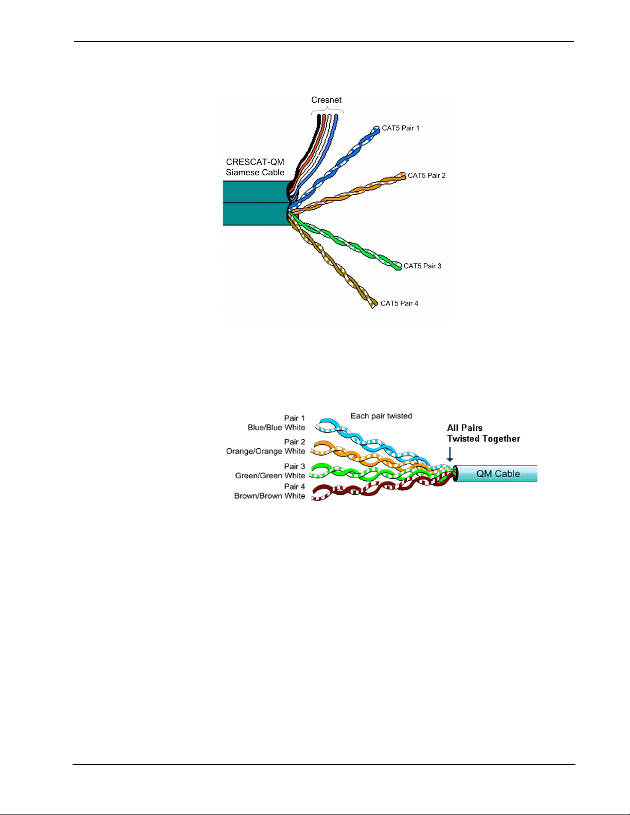
The QuickMedia Transport System
Using a new, proprietary signal routing solution, signals such as composite video,
S-video, RGBHV, audio, microphone and control, are all transported using a single
cable solution called QuickMedia™ (QM).
The QuickMedia Transport System port is capable of managing computer, video, and
audio signals simultaneously throu g h one CAT5E/UTP wire, simplifying
MediaManager installations.
Routing CAT5E/UTP cable is less expensive and much simpler than routing multicolored, multi-conductor coax cable. All Crestron products using the QuickMedia
Transport System are capable of sending and receiving QuickMedia signals via
standard CAT5E/UTP cable. Crestron recommends Belden Media-Twist cable, and
Crescat-QM. Installation of any QuickMedia device is as simple as installing one set
of QuickMedia wires from output to input. Installations are flexible, affordable, and
fast.
1 2 3 4 5 6 7 8
The Crescat-QM cable contains one CAT5E cable and one Cresnet cable in a
siamese jacket.
40 • Crestron CAT5 Wiring Reference Guide - DOC. 6137A
Page 45
Crestron CAT5 Wiring Reference Guide
QuickMedia Cable – CRESCAT-QM
The QuickMedia receiver performs frequency compensation on each video input to
compensate for skew. Signal skew occurs when part of the signal is delay e d wit h
respect to other signal components. The amount of skew largely depends on the
length of the QuickMedia cable. Unequal wire lengths are created because CAT5
consists of twisted pairs that are twisted together in the cable.
The total accumulated skew from QM transmitter to QM receiver must not exceed 15
ns (nanoseconds). Crestron recommends a cable with a rating of less than or equal to
15 ns over its entire length.
For example, if using a cable with a rating of 15 ns/100 meters (100 meters = 328
feet), connecting the QM-WMC/QM-WMIC QM transmitter with 150 ft. of cable to
a QM-MD7x2 switcher, and then using another 150 ft. to connect the QM-RMCRX
receiver, the accumulated skew over the entire 300 feet should not exceed 15 ns.
QuickMedia allows composite and S-video resolutions of 800 x 600 to 1600 x 1200
at 60 Hz. Longer lengths of cable may experience a loss of bandwidth when viewing
at high video resolutions.
The pin assignment is based on the EIA/TIA 568B RJ-45 Jack standard.
Reference Guide – DOC. 6137A Crestron CAT5 Wiring • 41
Page 46

Reference Guide Crestron CAT5 Wiring
QuickMedia Pin and Pair Assignment
RJ-45 MALE CONNECTOR RJ-45
PIN
NUMBER
1 2 White/Orange - RGB Red - Chrominance
2 2 Orange + RGB Red + Chrominance
3 3 White/Green - RGB Green - Luminance
4 1 Blue + Audio + Audio
5 1 White/Blue - Audio - Audio
6 3 Green + RGB Green + Luminance
7 4 Whit e/Brown - RGB Blue - Composite
8 4 Brown + RGB Blue + Composite
CAT5E
PAIR
NUMBER
WIRE COLORS QM
ASSIGNMENT
RGB AND AUDIO
QM ASSIGNMENT
COMPOSITE,
S-VIDEO AND AUDIO
42 • Crestron CAT5 Wiring Reference Guide - DOC. 6137A
Page 47

Crestron CAT5 Wiring Reference Guide
Crestron Certified Wire and Cable
NOTE: Crestron wire may be purchased directly from Crestron
(www.crestron.com).
CRESNET - Cresnet Control Cable: Basic cable for interconnecting the Crestron
Control Network.
CRESNET – Cresnet Control Cable – Non-Plenum
Construction Pair 1 – 22 AWG Twisted (four turns per
Outer Jacket
Material
Outer Jacket
Color
Overall Diameter Nominal 0.250 in (0.635 cm)
foot), Shielded, Low-capacitance. Pair
Color: Blue and white
Pair 2 – 18 AWG Parallel (wrapped
around the shield of pair 1).
Pair Color: Red and black
Flame Retardant PVC
Teal with Yellow Stripe
CRESNET – Cresnet Control Cable – Plenum
Construction Pair 1 – 22 AWG Twisted (four turns per
Outer Jacket
Material
Outer Jacket
Color
Overall
Diameter
foot), Shielded, Low-capacitance. Pair
Color: Blue and white
Pair 2 – 18 AWG Parallel (wrapped
around the shield of pair 1).
Pair Color: Red and black
Plenum, Flexible, Low Smoke
Teal
Nominal 0.250 in (0.635 cm)
CRESCAT: Basic Crestron Control Cable combined with a single CAT5E cable.
CRESCAT – CAT5E plus Cresnet Control Cable
Construction Shielded, Low Capacitance Cresnet
Outer Jacket
Material
Color Teal with co-extruded Red Stripe
Overall
Diameter
CRESCAT-D: Basic Crestron Control Cable combined with a two CAT5E cables,
for use with Isys
®
TPS-6000, TPS-5000 and TPS-2000L touchpanels.
cable + one CAT5E cable
Flame Retardant PVC
Nominal 0.530 in (1.346 cm)
Reference Guide – DOC. 6137A Crestron CAT5 Wiring • 43
Page 48

Reference Guide Crestron CAT5 Wiring
CRESCAT-D – 2 CAT5E plus Cresnet Control Cable
Construction Shielded, Low Capacitance Cresnet
Outer Jacket
Material
Outer Jacket
Color
Overall
Diameter
CRESCAT-Q: Basic Crestron Control Cable combined with a four CAT5E cables,
for use with fully implemented media distribution systems. Applications include
bi-directional balanced audio and video home automation and control, and Ethernet
data network.
CRESCAT-Q – 4 CAT5E plus Cresnet Control Cable
Construction Shielded, Low Capacitance Cresnet
Outer Jacket
Material
Outer Jacket
Color
Overall Diameter Nominal 0.680 in (1.727 cm)
cable + two CAT5E cables
Flame Retardant PVC
Teal with co-extruded Black Stripe
Nominal 0.560 in (1.422 cm)
cable + four CAT5E cables
Flame Retardant PVC
Teal with co-extruded White Stripe
CRESCAT-DC: Basic Crestron Control Cable combined with a two CAT5E cables
and two RG6 Quad Shield cables, for use with balanced audio/video, composite or
S-video over coax, Broadband dual-DSS distribution, and home automation and
control.
CRESCAT-DC – 2 CAT5E plus 2 RG6 Quad Shield plus Cresnet Control Cable
Construction Shielded, Low Capacitance Cresnet
Outer Jacket
Material
Outer Jacket
Color
Overall Diameter Nominal 0.800 in (2.032 cm)
cable + two CAT5E cables + two RG6
Quad cables
Flame Retardant PVC
Teal with co-extruded Orange Stripe
CRESCAT-QM: The Crescat-QM cable contains one CAT5E cable and one
Cresnet cable in a siamese jacket.
44 • Crestron CAT5 Wiring Reference Guide - DOC. 6137A
Page 49

Crestron CAT5 Wiring Reference Guide
CRESCAT-QM – One CAT5E Cable plus One Cresnet Control Cable
Construction Shielded, Siamese, Low Capacitance
Outer Jacket
Material
Color Teal
Overall Diameter Nominal 0.530 in (1.346 cm)
Cresnet cable + one CAT5E cable
Flame Retardant PVC
Further Inquiries
If you cannot locate specific information or have questions after reviewing this
guide, please take advantage of Crestron's award winning customer service team by
calling the Crestron corporate headquarters at 1-888-CRESTRON [1-888-273-7876].
For assistance in your local time zone, refer to the Crestron website
(www.crestron.com) for a listing of Crestron worldwide offices.
You can also log onto the online help section of the Crestron website
(www.crestron.com) to ask questions about Crestron products. First-time users will
need to establish a user account to fully benefit from all available features.
Reference Guide – DOC. 6137A Crestron CAT5 Wiring • 45
Page 50

Reference Guide Crestron CAT5 Wiring
Glossary
A
ACR: Attenuation to Crosstalk Ratio.
Attenuation: The decrease, or loss, of signal power, measured in decibels (the
opposite of gain).
AWG: American Wire Gauge is a standard measurin g gau ge fo r no n -ferrous
conductors (i.e., aluminum and copper). AWG is a measure of conductor diameter.
Increasing the gauge number decreases the wire diameter.
C
Chrominance: The color portion of a video signal carrying the saturation and tint
(hue) information for any given point in the image.
Composite Video: Video information carried in a single signal that combines color
(chrominance) and brightness (luminance) information, plus horizontal and vertical
sync.
Crosstalk: See Near-End Crosstalk.
D
dB (Decibel): A dB is a unit of signal strength measurement, usually the relation
between a transmitted signal and the signal source.
Delay Skew: The difference between the pair with the least delay and the pair with
the most delay, as measured in nanoseconds.
E
Electromagnetic Interference (EMI): The interference in signal transmission or
reception caused by the radiation of electrical and magnetic fields.
Equal Level Far-End Crosstalk (ELFEXT): Calculated by subtracting attenuation
from the far-end crosstalk loss.
F
Far End Crosstalk Loss (FEXT): Pair-to-pair far end crosstalk is the quantity of
undesired signal coupling at the receiving end of a pair of wires.
I
IEEE: Institute of Electrical and Electronic Engineers, a publishing and standards-
making organization.
J
Jack: A receptacle used in conjunction with a plug to make electrical contact
between communication circuits. A jack is the female component of a plug/jack
connector system.
L
Luminance: The black and white portion of a video signal which carries the
information for brightness, darkness and contrast, plus the horizontal and vertical
sync.
M
Mbps, MegaBits Per Second: One million bits per second.
46 • Crestron CAT5 Wiring Reference Guide - DOC. 6137A
Page 51

Crestron CAT5 Wiring Reference Guide
MHz, MegaHertz: A unit of frequency denoting one million Hertz (i.e., 1,000,000
cycles per second).
N
Near-End Crosstalk (NEXT): Electrical noise coupled from one pair of wires to
another within a multi-pair cable.
P
Power Sum: The combined performance of all cable pair combinations to ensure
enough headroom to handle crosstalk.
Propagation Delay: The time between when a signal is transmitted and received on
the other end, measured in nanoseconds.
R
RG6: Coaxial 75 ohm cable.
S
Standards: Agreed principles of protocol . Committees working under various tra de
and international organizations set industry standards.
S-video: Method of transmitting video signals by separating out the chrominance
(color) and luminance (brightness) portions of the video signal resulting in superior
picture quality versus composite video.
References
T
T1: A standard for digital transmission in North America. A digital transmission link
with a capacity of 1.544 Mbps (1,544,000 bits per second.) T1 lines are used for
connecting networks across remote distances. Bridges and routers are used to
connect LANs over T1 networks.
Twisted Pair: Two insulated copper wires twisted around each other to reduce
induction (thus interference) from one wire to the other.
U
UTP: Unshielded Twisted Pair.
Numeric
100BASE-T: The IEEE standard that defines the requirement for sending
information at 100 Mbps on unshielded twisted-pair cabling.
Category 5E information courtesy of:
• The Siemon Company
• Southwire Cyber Technologies, Inc.
• Hubbell-Premise.com
• Microtest
• LANshack.com
• Acteon.net
Reference Guide – DOC. 6137A Crestron CAT5 Wiring • 47
Page 52

Crestron Electronics, Inc. Reference Guide – DOC. 6137A
15 Volvo Drive Rockleigh, NJ 07647 11.04
Tel: 888.CRESTRON
Fax: 201.767.7576 Specifications subject to
www.crestron.com change without notice.
 Loading...