

Page 1

Crestron 2-Series Control Systems
Reference Guide
Page 2

This document was prepared and written by the Technical Documentation department at:
Crestron Electronics, Inc.
15 Volvo Drive
Rockleigh, NJ 07647
1-888-CRESTRON
All brand names, product names and trademarks are the property of their respective owners.
©2006 Crestron Electronics, Inc.
Page 3

Crestron 2-Series Control Systems Reference Guide
Contents
2-Series Control Systems 1
Introduction ...............................................................................................................................1
Programming Tools & Utilities ................................................................................................. 3
SIMPL Windows......................................................................................................... 3
VisionTools Pro-e .......................................................................................................3
Crestron Toolbox......................................................................................................... 3
Viewport (Limited Use) .............................................................................................. 4
Establishing Communications with the Control System............................................................5
Serial Connection ........................................................................................................ 5
TCP/IP Connection ..................................................................................................... 9
Modem Connection................................................................................................... 11
Passthrough Mode (Viewport Only) .........................................................................12
Troubleshooting Communications........................................................................................... 13
2-Series Console Commands................................................................................................... 16
Introduction ............................................................................................................... 16
SIMPL Windows Symbols........................................................................................ 16
Command Groups .....................................................................................................18
Processor Groups....................................................................................................... 21
Command Structure................................................................................................... 22
2-Series Memory & Directory Structure .................................................................................23
Introduction ............................................................................................................... 23
Non-Volatile Random Access Memory (NVRAM) Disk .........................................25
NVRAMREBOOT.................................................................................................... 27
Running Programs from Compact Flash ................................................................... 28
2-Series Control System Error Messages ................................................................................ 29
Introduction ............................................................................................................... 29
Viewing Error Messages with the Front Panel.......................................................... 29
Viewing Error Messages with Crestron Toolbox...................................................... 30
Error Levels............................................................................................................... 31
Error Format.............................................................................................................. 31
Master-Slave Modes................................................................................................................ 32
Introduction ............................................................................................................... 32
Definitions................................................................................................................. 32
Master-Slave Operating Guidelines ..........................................................................33
Configuring the Control System................................................................................ 34
Configuration and Programming............................................................................... 37
Uploading.................................................................................................................. 41
Dynamic Host Configuration Protocol (DHCP)...................................................................... 42
Introduction ............................................................................................................... 42
Windows DHCP/DNS Server Configuration ............................................................ 42
Control System Configuration................................................................................... 43
Secure Sockets Layer (SSL) .................................................................................................... 46
Introduction ............................................................................................................... 46
SSL Configuration..................................................................................................... 48
Uploading & Using Web Pages............................................................................................... 54
Crestron VisionTools Pro-e....................................................................................... 54
Reference Guide – DOC. 6256A Contents • i
Page 4

Crestron 2-Series Control Systems Reference Guide
Crestron Toolbox....................................................................................................... 54
SIMPL Windows....................................................................................................... 56
Web Page Basics ....................................................................................................... 56
Compiling and Uploading a Program ...................................................................................... 60
Compiling a Program in SIMPL Windows ............................................................... 60
Uploading a SIMPL Windows Program.................................................................... 60
IP Tables.................................................................................................................... 61
Creating the Default IP Table from SIMPL Windows .............................................. 62
Creating and Modifying IP Tables with Crestron Toolbox....................................... 63
Uploading Touchpanel Projects............................................................................................... 65
Firmware Upgrade................................................................................................................... 67
Updating the Operating System............................................................................................... 69
Introduction ............................................................................................................... 69
Procedure................................................................................................................... 69
Test Manager........................................................................................................................... 71
Incoming Data........................................................................................................... 71
Status Window ..........................................................................................................72
Trace Window........................................................................................................... 74
Network Analyzer.................................................................................................................... 75
Super-Debugger....................................................................................................................... 76
C2N-NPA8 Network Poll Accelerator .................................................................................... 77
Support Information ................................................................................................................79
Frequently Asked Questions .....................................................................................79
Watchdog Protection ................................................................................................. 80
Further Inquiries........................................................................................................ 80
Future Updates ..........................................................................................................81
Appendix A: Interfacing a Control System with a Modem ..................................................... 82
Quick Guide .............................................................................................................. 82
Cable Requirements (2-Series Control System to Modem) ......................................84
Cable Requirements (PC to Modem) ........................................................................85
Modem Configuration (Control System Modem) ..................................................... 85
Modem Communications Speed................................................................................ 86
Notes for QM-RMC and QM-RMCRX(-BA)........................................................... 86
2-Series Console Commands for Modem Configuration .......................................... 87
Appendix B: Passthrough Mode.............................................................................................. 89
Appendix C: Console Command Listing................................................................................. 91
Appendix D: Error Message Definitions ............................................................................... 123
Notice-Level Messages ...........................................................................................123
Warning-Level Messages........................................................................................ 123
Error-Level Messages.............................................................................................. 127
Appendix E: Super-Debugger Command Listing.................................................................. 152
Appendix F: Join Number Remapping (JNR) ....................................................................... 154
Introduction ............................................................................................................. 154
Programming........................................................................................................... 155
Uploading................................................................................................................ 172
Index...................................................................................................................................... 173
Software License Agreement................................................................................................. 178
Reference Guide – DOC. 6256A Contents • ii
Page 5

Crestron 2-Series Control Systems Reference Guide
2-Series Control Systems
Introduction
Crestron® control systems are at the center of every Crestron facility control system.
The 2-Series line of control systems share commonality across the product line and
offer a variety of development tools and techniques previously unavailable in
previous Crestron control systems. Crestron 2-Series control systems include the
AV2 and PRO2. Consult the latest Crestron Product Catalog for a complete list of all
2-Series control systems.
The common architecture shared by 2-Series control systems allows similar
programming tools, console commands, programming methods, and other practices
to be used across the product line. This document will discuss many of the tools,
features, and techniques used to program and troubleshoot a Crestron control system:
• Programming Tools & Utilities
• Establishing Communications with the Control System
• Troubleshooting Communications
• 2-Series Console Commands
• 2-Series Memory & Directory Structure
• 2-Series Control System Error Messages
• Master-Slave Modes
• Dynamic Host Configuration Protocol (DHCP)
• Secure Sockets Layer (SSL)
• Uploading & Using Web Pages
• Compiling and Uploading a Program
• Uploading Touchpanel Projects
• Firmware Upgrade
• Updating the Operating System
• Test Manager
• Network Analyzer
• Super-Debugger
• C2N-NPA8 Network Poll Accelerator
Reference Guide – DOC. 6256A 2-Series Control Systems • 1
Page 6

Reference Guide Crestron 2-Series Control System
Each of the 2-Series control systems has unique features to meet a variety of system
requirements. The following table lists all of the Crestron 2-Series control systems
and their key features.
2-Series Control Systems and Features
PRO2
AV2
RACK2
CP2E
CP2
MC2E
MC2W
MP2E
MP2
QM-RMC
QM-RMCRX(-BA)
CNX-DVP4
C2N-DVP4I
Processor:
2-Series Engine and Dual-bus Architecture XXXXXXXXXXX X X
4GB Compact Flash Memory Card Slot XXX X X
Cresnet:
Cresnet Port (Master/Slave) XXXXXXXXX X X X
Integrated Cresnet Network Hub XX
C2N-NPA8 Support via Com Port XX XXXXXX
C2N-NPA8 Support via Ethernet Port (a) (a) (a) XXX X(a)
Ethernet:
10/100 Ethernet Port w/SSL & DHCP (a) (a) (a) XXXXXX(a)
e-Control 2 Enabled (a) (a) (a) XXXXXX(a)
Built-in Firewall, NAT and Router (a) (a) (a) (a)
Integrated Control Ports:
Com (RS-232/422/485) 6+ 6+ (b) 332222 (b)
Com (RS-232 Only) 22 4
IR/Serial 8+ 8+ (b) 88444411 (b)
Versiport I/O 8+ 8+ (b) 884444 8+
Digital Input 44
Low-Voltage Relay 8+ 8+ (b) 884444 8+
Control Card Expansion Slots:
Y-Bus 3 (c) 12 2
Built-in Wireless:
1-way 418 or 434 MHz 1-way RF X
38 kHz RC5 Infrared (IR) via CNXRMIRD XXXX
Audio, Video and RGB:
Integrated AV Switcher/Processor XX X
Integrated QuickMedia Transport X
Integrated Digital Video Processor X
Power Supply:
Internal Univeral Power Supply XX X
External Power Supply Included XXXXXX
Separate Power Supply Required XXX X
Mounting:
EIA Rack Units (Ears Included) 224111111 2
Non-Rack Mount (d) (d) (e)
Notes:
a. Requires appropriate Z-bus card c. 3 Y-bus slots, requires optional CAGE2
b. Requires appropriate Y-bus card(s) d. Optional projector pole mount available
Z-Bus 114 1
e. Installs in CAEN automation cabinets
PAC2
2 • 2-Series Control Systems Reference Guide – DOC. 6256A
Page 7

Crestron 2-Series Control Systems Reference Guide
Programming Tools & Utilities
Many of the activities discussed in this document require the use of Crestron’s suite
of programming tools and utilities. They include:
Pro-e
®
• SIMPL™ Windows
• VisionTools
• Crestron Toolbox
• Test Manager
• Viewport (limited use)
The latest versions can be obtained from the Crestron website
(www.crestron.com
NOTE: Crestron software and any files on the website are for Authorized Crestron
dealers and Crestron Authorized Independent Programmers (CAIP) only. New users
may be required to register to obtain access to certain areas of the site (including the
FTP site).
®
/updates).
SIMPL Windows
SIMPL Windows is Crestron's software for programming Crestron control systems.
It provides a well-designed graphical environment with a number of windows in
which a programmer can select, configure, program, test, and monitor a Crestron
control system. SIMPL Windows offers drag and drop functionality in a familiar
Windows
®
environment.
VisionTools Pro-e
Crestron VisionTools Pro-e (also referred to as VT Pro-e) Windows-based software
is for drawing touchscreen pages by using two and three-dimensional graphics and
text as well as video and sounds (recorded as WAV files). A set of pages make up a
project. Each of these “projects” can be loaded in a Crestron touchpanel or used as a
set of web pages stored on a control system for remote access to control system
functions.
Crestron Toolbox
Crestron Toolbox is a replacement for Crestron Viewport. Crestron Toolbox is a
broad-based software package that accomplishes multiple system tasks, primarily
using an RS-232 or TCP/IP connection between a PC and one or more Crestron
control systems.
You can use Crestron Toolbox to:
• Observe system processes.
• Upload operating systems and firmware.
• Upload programs and touchpanel projects.
• Set or change device Network IDs.
• Change the serial number reported by a device.
Reference Guide – DOC. 6256A 2-Series Control Systems • 3
Page 8

Reference Guide Crestron 2-Series Control System
• Run scripts to automate tasks.
• Perform system diagnostics, and much more.
Crestron Toolbox allows you to perform these functions using simple graphical
views and click and drag methods.
Crestron Toolbox also contains the Network Analyzer and Test Manager (expected
2Q 2006) utilities.
Network Analyzer
The Network Analyzer utility helps to identify Cresnet® network problems that can
be caused by faulty devices, electrical shorts, or breaks in network wiring. Network
Analyzer takes a sample of the voltage levels on the Cresnet "Y" and "Z" wires.
Network Analyzer is launched from within Crestron Toolbox by clicking the
Network Analyzer icon
For more information on Network Analyzer, refer to “Network Analyzer” on page
75.
Test Manager
The Test Manager is a utility for testing and debugging a SIMPL Windows program,
by monitoring the status of selected signals in real time. Test Manager can test any
program that has been compiled and uploaded to the control system.
.
Test Manager is launched from within SIMPL Windows by clicking the Test
Manager button or by selecting Tools | Test Manager. Test Manager can also be
opened as a standalone program.
For more information on Test Manager, refer to “Test Manager” on page 71.
Viewport (Limited Use)
Where noted in this guide, the Crestron Viewport can be used to perform certain
functions
Viewport is available as a pull-down command from SIMPL Windows and VT Pro-e
(Tools | Viewport) or as a standalone utility. The Viewport utility performs multiple
system tasks, primarily via an RS-232 or TCP/IP connection between the control
system and a PC. It is used to observe system processes, upload new operating
systems and firmware, change system and network parameters, and communicate
with network device consoles and touchpanels, among many other tasks. Viewport
can also function as a terminal emulator for generic file transfer. All of these
functions are accessed through the commands and options in the Viewport menus.
NOTE: Except where noted, Crestron Toolbox should be used.
4 • 2-Series Control Systems Reference Guide – DOC. 6256A
Page 9

Crestron 2-Series Control Systems Reference Guide
Establishing Communications with the Control System
Whether uploading programs, troubleshooting, or performing diagnostics
communication between the control system and a PC must be established.
In electronic terms, a “console” provides a means of communication between an
operator and the central processing unit of a computer. Crestron Toolbox lets you
talk to the console of a 2-Series dual bus control system. Crestron Toolbox allows
the operator to establish, monitor, and troubleshoot communications directly with the
control system.
Depending on the control system’s capabilities, the following communication
protocols may be used to communicate with a control system:
• Serial communication (RS-232) with a PC via the COMPUTER port
on the control system
• Ethernet communication via CTP (Crestron Terminal Protocol –
reserved port number, default port is 41795) *
• Ethernet communication via Secure CTP over a SSL connection to port
41797 at the IP address of the processor*
• Telnet (default port is 23)*
• Cresnet for processors operating in the Cresnet slave mode (refer to
“Master-Slave Modes” on page 32)
* These methods are only available if the control system supports Ethernet.
Whether the intent is to use RS-232 or Ethernet, these methods initially require
connection of the control system to a PC via RS-232.
Another method for submitting a command to the console is to use the “Console” or
“User Program Commands “ symbols in SIMPL Windows in the control system
program. The Console symbol transmits and receives serial data to and from the
control system’s console. The User Program Commands symbol allows data typed at
the console to be sent to the program. For more information on the Console symbol,
refer to “Console Logic Symbol” on page 16. For more information on the User
Program Commands symbol, refer to “User Program Commands Symbol” on page
17.
Serial Connection
Complete the following steps to establish a serial connection between a PC and a
control system.
1. As shown in the following diagram, connect the COMPUTER port on the
control system to one of the COM ports (usually COM 1) on the PC. Use a
straight-through RS-232 cable with a DB9 male connector on one end and a
DB9 female connector on the other. Most commercially available cables are
acceptable; they should have at least five pins for transmit, receive, ground,
and hardware handshaking (pins 2, 3, 5, 7, 8).
NOTE: Most of the Crestron 2-Series control systems use a straightthrough RS-232 cable. However, some models use a null-modem cable.
Refer to your control system’s Operations Guide for cable details.
Reference Guide – DOC. 6256A 2-Series Control Systems • 5
Page 10

Reference Guide Crestron 2-Series Control System
Typical Connection Diagram for Establishing Communication
Control System
RS-232
NOTE: Certain control systems do not have a COMPUTER port and
require an alternate method for establishing serial communications. Refer to
your control system’s Operations Guide if the control system does not have
a COMPUTER port.
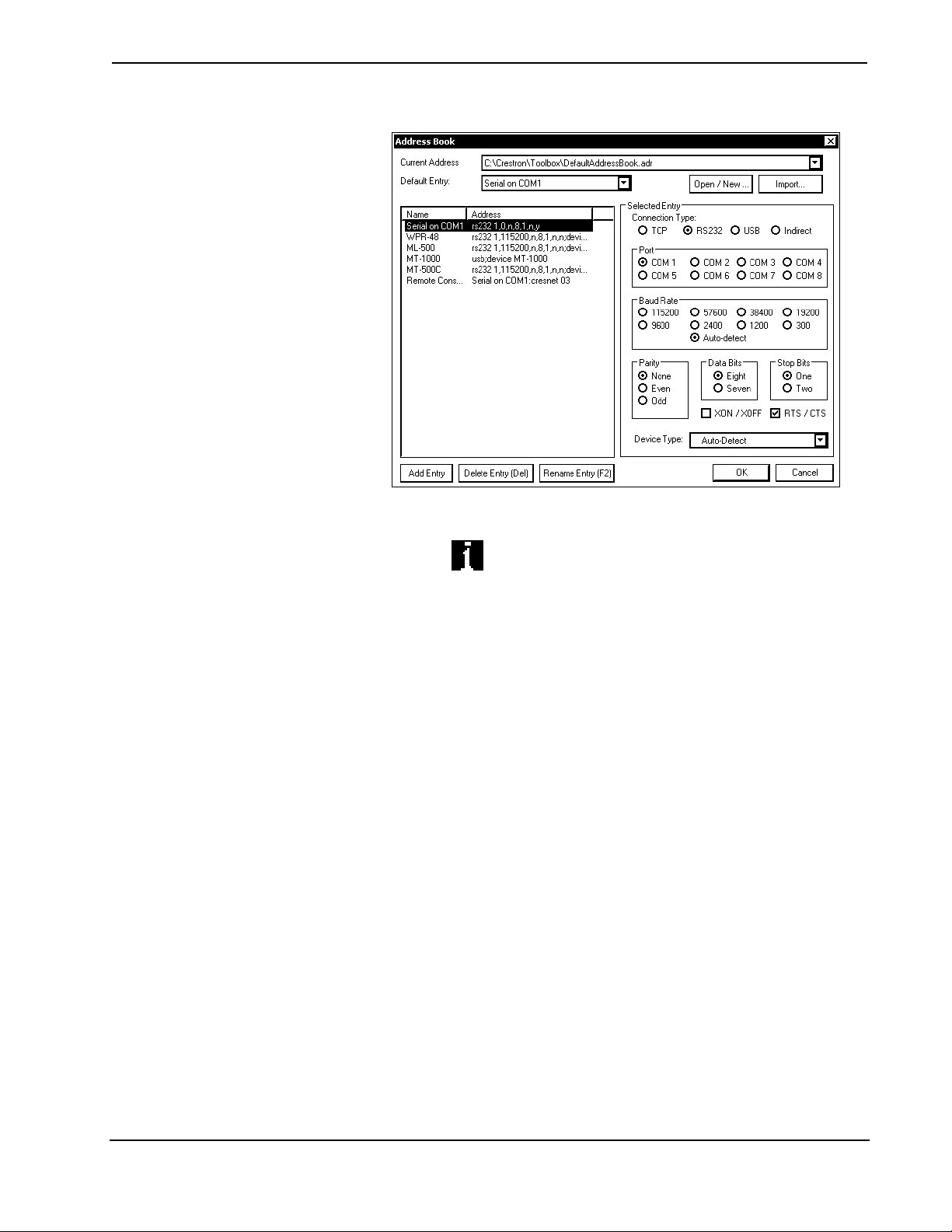
2. Open Crestron Toolbox and click Tools | Manage Address Book to display
a list of available devices. Select a connection to a control system (if an
entry for one exists), or Serial on COM1 as the connection type. Serial on
COM1 is an address book entry for PC-to-control system communications
that is included with Crestron Toolbox.
The default settings for the Serial on COM1 entry, which will work with
most 2-Series control systems, are as follows:
• Port = COM 1. If the PC is to communicate with a control system
through a different serial port, select the correct COM port (COM1
through COM8) to be used.
• Baud rate = Auto-detect.
• Parity = None.
• Number of data bits = 8.
• Number of stop bits = 1.
• Hardware handshaking (RTS/CTS) enabled.
• Software handshaking (XON/XOFF) not enabled.
NOTE: If using a direct serial connection, an 8-bit serial connection must be used
when transferring a binary file. If a 7-bit serial connection is used, the transfer will
fail.
6 • 2-Series Control Systems Reference Guide – DOC. 6256A
Page 11
Crestron 2-Series Control Systems Reference Guide
“Address Book” Window – Serial Setup
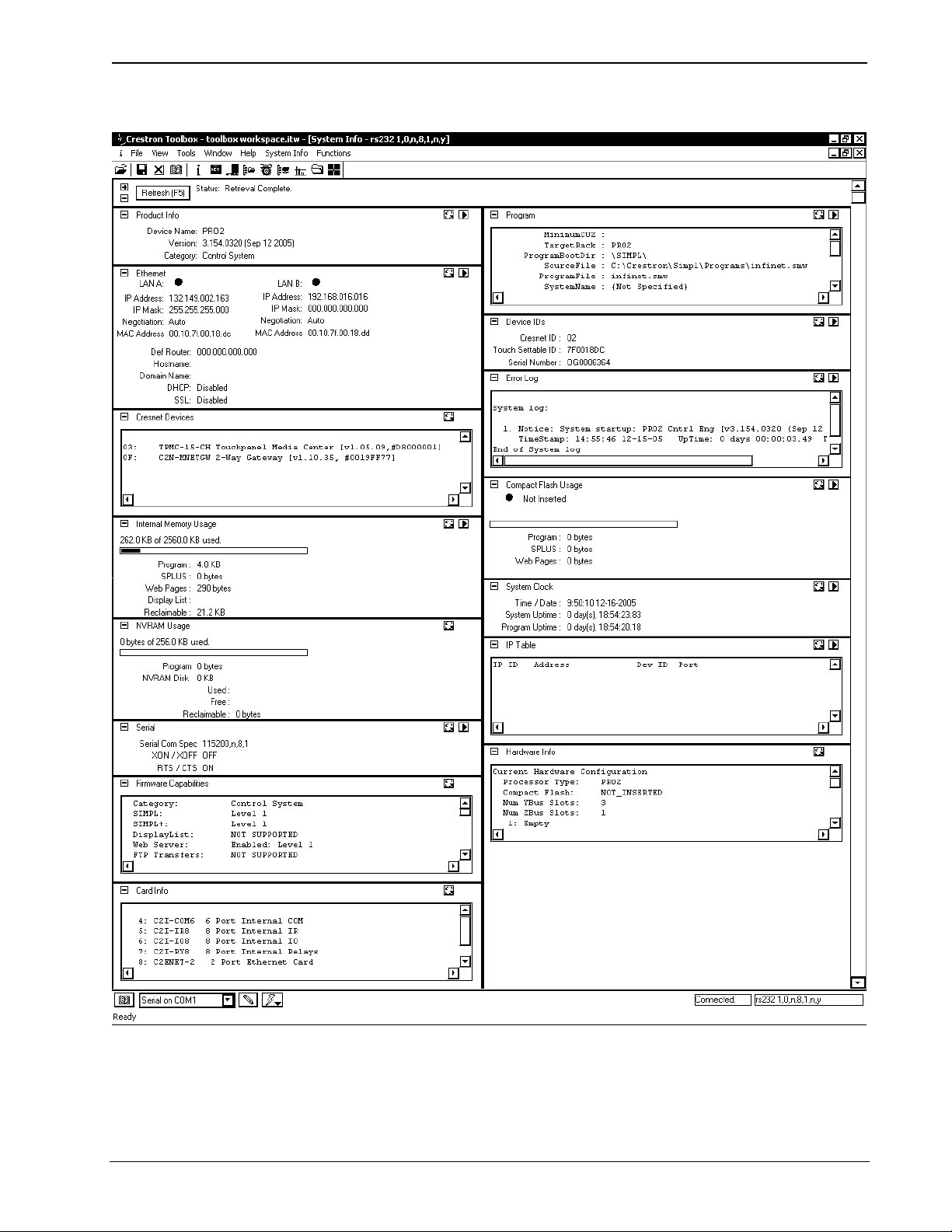
3. After setting the correct parameters, click OK to return to the Crestron
Toolbox main window.
4. Click the
entry for the control system or Serial on COM1 from the drop down list
(located on the bottom of the screen) if it is not already selected. If
communication is successful, the control system’s information is displayed
as shown in the following diagram.
icon to display the control system information. Select the
Reference Guide – DOC. 6256A 2-Series Control Systems • 7
Page 12
Reference Guide Crestron 2-Series Control System
“System Info” Window for PRO2
Once the system information is displayed a variety of functions are available to the
user. For more information, refer to the Crestron Toolbox help file.
8 • 2-Series Control Systems Reference Guide – DOC. 6256A
Page 13
Crestron 2-Series Control Systems Reference Guide
NOTE: Crestron Toolbox displays a customized list of functions depending on the
type of device with which it is communicating.
TCP/IP Connection
Before communicating with an Ethernet-enabled control system over TCP/IP, a static
IP address or the address/host name of the DHCP server (if DHCP is to be used)
must be obtained from the network administrator. The RS-232 connection previously
described must be used to configure the unit’s TCP/IP settings. After configuring the
IP information of the control system, further communications can be done over
TCP/IP. For more information, refer to the latest version of the Crestron e-Control
Reference Guide (Doc. 6052). The guide is available from the Crestron website
(www.crestron.com/manuals).
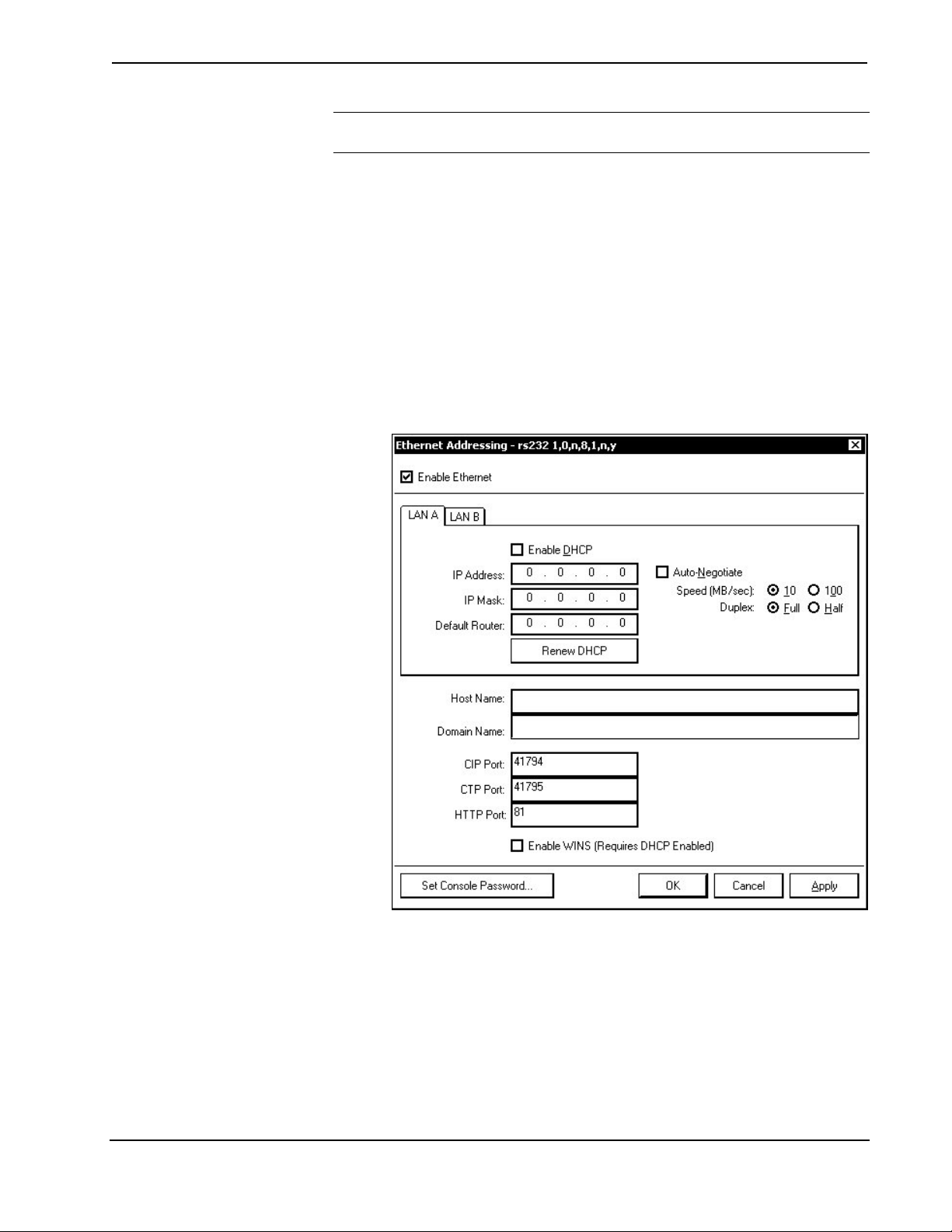
1. Select Functions | Ethernet Addressing… to open the “Ethernet
Addressing” window
“Ethernet Addressing” Window
2. Enable TCP/IP communications by checking Enable Ethernet and
configure for static or dynamic IP operation.
a) Static IP Operation
i. Clear (de-select) the Enable DHCP check box.
ii. Enter the static IP address and address mask in the address
fields. If applicable, enter the default gateway address. (If data
will not be routed outside the LAN, the default gateway can be
left blank.)
Reference Guide – DOC. 6256A 2-Series Control Systems • 9
Page 14

Reference Guide Crestron 2-Series Control System
The IP addresses of LAN A and LAN B cannot be the same.
iii. Enter the hostname in the Host Name field. The host name
identifies the control system on the network and is
automatically translated into the numerical IP address. The
host name can consist of up to 64 characters. Valid characters
are 0 – 9, A – Z (not case-sensitive), and the dash (hyphen
character). No other characters are valid. The host name
cannot begin with a dash or number.
If a host name is specified, you can enter this host name
instead of the IP address in the Address Book.
iv. The Domain Name is an additional qualifier that some
networks may need to resolve the name properly.
b) Dynamic IP Operation
i. Select the Enable DHCP check box to enable DHCP for
Windows 2000 Server.
ii. Select both the Enable DHCP and Enable WINS check
boxes for Windows NT 4.0 Server. The address of the WINS
server will be provided by the DHCP server.
iii. Enter the fully-qualified domain name (FQDN) of the control
system into the Host Name field. The host name identifies the
control system on the network and is automatically translated
into the numerical IP address. The host name can consist of up
to 64 characters. Valid characters are 0 – 9, A – Z (not casesensitive), and the dash (hyphen character). No other
characters are valid. The host name cannot begin with a dash
or number.
iv. If applicable, enter the domain into the Domain Name field.
This is only necessary if you are configuring DHCP on an
Ethernet connection to a control system that currently has a
static address. The domain name will be used to reconnect to
the control system after it reboots. With a serial connection,
the domain name does not need to be entered.
The domain name supplied by the DHCP server will overwrite
the domain name that is indicated in this field.
v. To request a new IP address from the DHCP server click the
Renew DHCP button.
NOTE: Other settings can be configured as well. Refer to the
Crestron Toolbox help file for more information.
3. Click OK to reboot the control system and set the new IP information.
Once the IP settings have been assigned, the control system can
communicate using the RS-232 connection or a TCP/IP connection.
For TCP/IP, use CAT5 straight through cables with 8-pin RJ-45 connectors
to connect the LAN port on the control system and the LAN port on the PC
to the Ethernet hub. Alternatively, you can use a CAT5 crossover cable to
connect the two LAN ports directly, without using a hub. The following
10 • 2-Series Control Systems Reference Guide – DOC. 6256A
Page 15
Crestron 2-Series Control Systems Reference Guide
figure illustrates pinouts for straight through and crossover RJ-45 cables.
Pins 4, 5, 7, and 8 are not used.
RJ-45 Pinouts
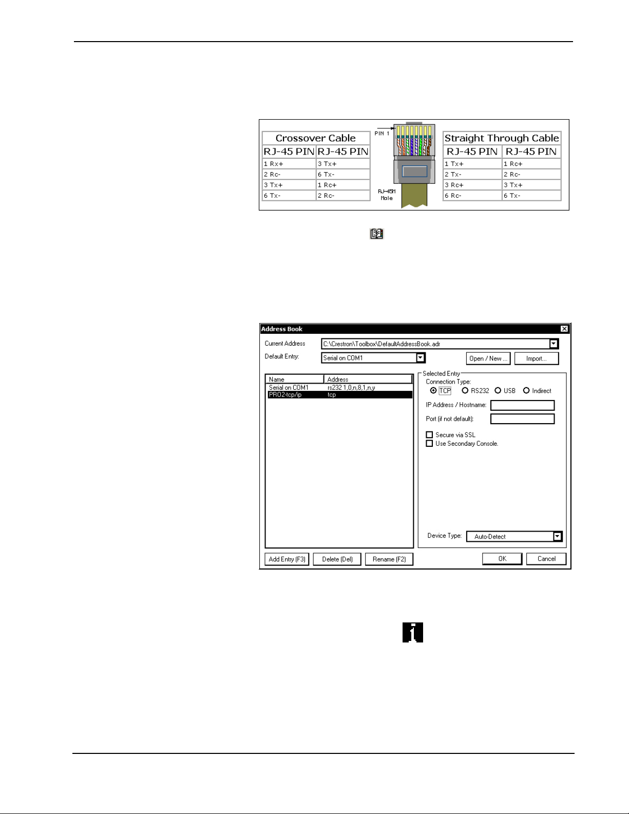
4. Open the address book in Crestron Toolbox by selecting Tools | Manage
Address Book or clicking
5. Create a new entry for the control system by clicking Add Entry or
pressing F3.
6. Enter a name for the control system connection and select TCP as the
connection type.
“Address Book” Window - Entering New TCP-IP Entry
.
7. Enter the IP address or hostname of the control system that was created on
page 10.
8. Click OK to save the address book entry.
9. To verify the connection, click the
“System Info” window will be displayed.
icon. If the settings are correct, the
Modem Connection
In applications where remote access to a control system is required but a serial or
Ethernet connection cannot be used, a modem can be connected to the control system
for communication with a PC console over a standard telephone line.
Reference Guide – DOC. 6256A 2-Series Control Systems • 11
Page 16

Reference Guide Crestron 2-Series Control System
NOTE: This procedure requires the use of the Crestron Viewport.
For detailed instructions and information, refer to “Appendix A: Interfacing a
Control System with a Modem” on page 82.
Passthrough Mode (Viewport Only)
Viewport can be used to communicate with devices that are attached to a control
system’s serial port. For more information, refer to “Appendix B: Passthrough
Mode” on page 89.
12 • 2-Series Control Systems Reference Guide – DOC. 6256A
Page 17

Crestron 2-Series Control Systems Reference Guide
Troubleshooting Communications
Use the following checklist if communication cannot be established with the control
system.
1. If possible remove any cards that are in the card cage, Cresnet devices and
the Ethernet card (if applicable).
2. Verify that you are using the correct cables. As described previously, most
RS-232 connections between a control system and a PC require a straightthrough serial cable. That is, pin 1 on one end is connected to pin 1 on the
other end. Pin 2 connects to pin 2, etc. With a TCP/IP connection, a CAT5
cable with 8-pin RJ-45 connectors and the wiring shown on page 11 must
be used.
NOTE: If you are using a serial adapter, Crestron Toolbox should be used
to establish PC-to-control system communications.
3. If using a serial connection, verify that the correct COM port on the PC has
been selected. Some computers have more than one COM port; some may
be internal (e.g., for a modem). Consult the manufacturer’s documentation
for further information about the COM ports on your PC.
4. Check the MSG / ERR LED indicator on the front panel of the control
system. If this LED is illuminated before a program is loaded, unplug the
unit and reapply power after a few seconds. If the LED illuminates again,
call Crestron customer service.
5. With a serial connection, reset the control system as follows:
a. Open Crestron Toolbox and open a text console connection to the
control system by clicking
system’s serial connection from the dropdown list on the bottom of the
page.
NOTE: The address book entry for the serial connection should
specify a 115200 baud rate. Do not select “Auto-Detect”.
b. Set the baud rate of the control system to 115200, as follows:
- Press and release the HW-R button on the unit’s front panel.
- Immediately press and hold the SW-R button for approximately
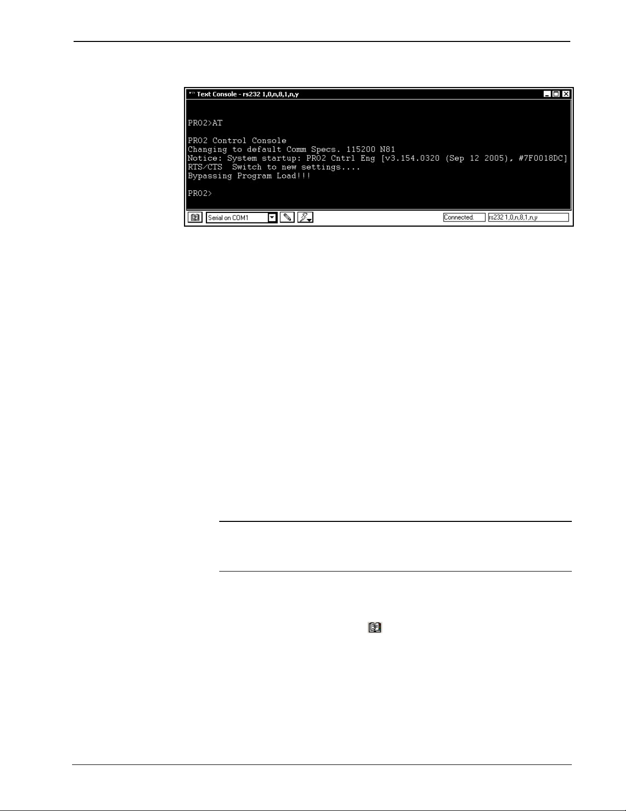
ten seconds. The Crestron Toolbox text console should display the
following message:
and selecting the entry for the control
Reference Guide – DOC. 6256A 2-Series Control Systems • 13
Page 18
Reference Guide Crestron 2-Series Control System
Crestron Toolbox Message (PRO2 Shown)
- Release the SW-R button.
c. If communication still cannot be established or the console is
displaying a <CS> prompt:
- Remove power from the control system.
- Press and hold the SW-R button on the front panel of the control
system.
- Reapply power to the control system while still holding the SW-R
button.
- The console should display the message previously shown.
- Release the SW-R button.
d. If communication still cannot be established, use the System Monitor
as described in the following paragraph.
If after performing all of the troubleshooting steps described in “Troubleshooting
Communications”, communication can still not be established or the control system
is still locked-up, perform the following to reload the control system’s firmware.
To erase and reinstall the control system firmware:
NOTE: This procedure will erase the control system’s firmware and reinstall it. If
problems persist before a SIMPL Windows program is loaded, contact Crestron’s
True Blue Technical Support Group. If the system locks up after a SIMPL Windows
program is loaded, there is probably an issue with the SIMPL Windows program.
1. Connect a serial cable (If using the QM-RMC or the QM-RMCRX(-BA),
use a null modem cable) from the control system to a PC.
2. Open the address book in Crestron Toolbox by selecting Tools | Manage
Address Book or clicking
3. Create a new address book entry with the following settings:
.
• Port = COM 1. If the PC is to communicate with a control system
through a different serial port, select the correct COM port (COM1
through COM8) to be used.
• Baud rate = 57600.
• Parity = None.
14 • 2-Series Control Systems Reference Guide – DOC. 6256A
Page 19

Crestron 2-Series Control Systems Reference Guide
• Number of data bits = 8.
• Number of stop bits = 1.
• Hardware handshaking (RTS/CTS) enabled.
• Software handshaking (XON/XOFF) not enabled.
4. Power down the control system.
5. In Crestron Toolbox, open a text console to the new address book entry.
6. While powering up the control system, press and hold ALT + K on the
keyboard (for the QM-RMC and QM-RMCRX(-BA), press Enter after
pressing ALT + K) until the following text (or similar) appears in the
Crestron Toolbox text console:
System Monitor [v1.001 (0001)]
12-19-01 16:25:23 32 MB RAM, 4MB FLASH
CS>
7. Increase the baud rate to 115200 by opening the “System Info” window,
selecting Functions | Serial Communications, and selecting 115200 as the
new baud rate. Click OK or Apply to set the new baud rate.
NOTE: Crestron Toolbox will automatically change the baud rate it uses to
communicate with the control system for the current session to ensure that
communications are maintained.
8. From the text console window, adjust the baud rate of the PC to control
system connection by clicking
rate.
9. At the control system prompt, type erase and press Enter. The following
text appears in the console window.
CS>erase
->25%->50%->75%->100%
Done
CS>
10. Send the new firmware file as described in “Firmware Upgrade” on page
67.
NOTE: The following processor firmware versions require the selection of
a CE*.CSU file that can be extracted from the .CUZ file using WinZip or
other ZIP file extraction tool:
• CNX-DVP4/C2N-DVP4DI: 2.006, 3.017
• MP2/MP2E: 3.016
• QM-RMC: 3.052
and selecting 115200 as the new baud
After extracting the CSU file, select it and click Open.
Once “Completed Successfully” appears in the text console window, close the text
console window.
Reference Guide – DOC. 6256A 2-Series Control Systems • 15
Page 20

Reference Guide Crestron 2-Series Control System
2-Series Console Commands
Introduction
The 2-Series processor is capable of understanding and responding to a set of
recognizable words known as console commands. The processor, in essence, is a
computer capable of interpreting commands received by the console via different
methods. Methods include:
• Serial communication (RS-232) with a PC via the COMPUTER port
on the control system
• Ethernet communication via CTP (Crestron Terminal Protocol –
reserved port number, default port is 41795) *
• Ethernet communication via Secure CTP over a SSL connection to port
41797 at the IP address of the processor*
• Telnet (default port is 23)*
• Cresnet for processors operating in the Cresnet slave mode (refer to
“Master-Slave Modes” on page 32)
* These methods are only available if the control system supports Ethernet.
Another method for submitting a command to the console is to use the “Console” or
“User Program Commands “ symbols in SIMPL Windows in the control system
program. The Console symbol transmits and receives serial data to and from the
control system’s console. The User Program Commands symbol allows data typed at
the console to be sent to the program.
NOTE: The method of transmitting each command to the control system varies
from command to command. Refer to “Appendix C: Console Command Listing” on
page 91 for a complete list of commands and their possible sources.
SIMPL Windows Symbols
Console Logic Symbol
Use the Console logic symbol to activate console commands via the SIMPL
Windows program. This feature is available for advanced programmers of SIMPL
Windows.
The Console logic symbol only appears in the System Control folder in the Symbol
Library, after enabling a special symbol set for display. To enable this set while in
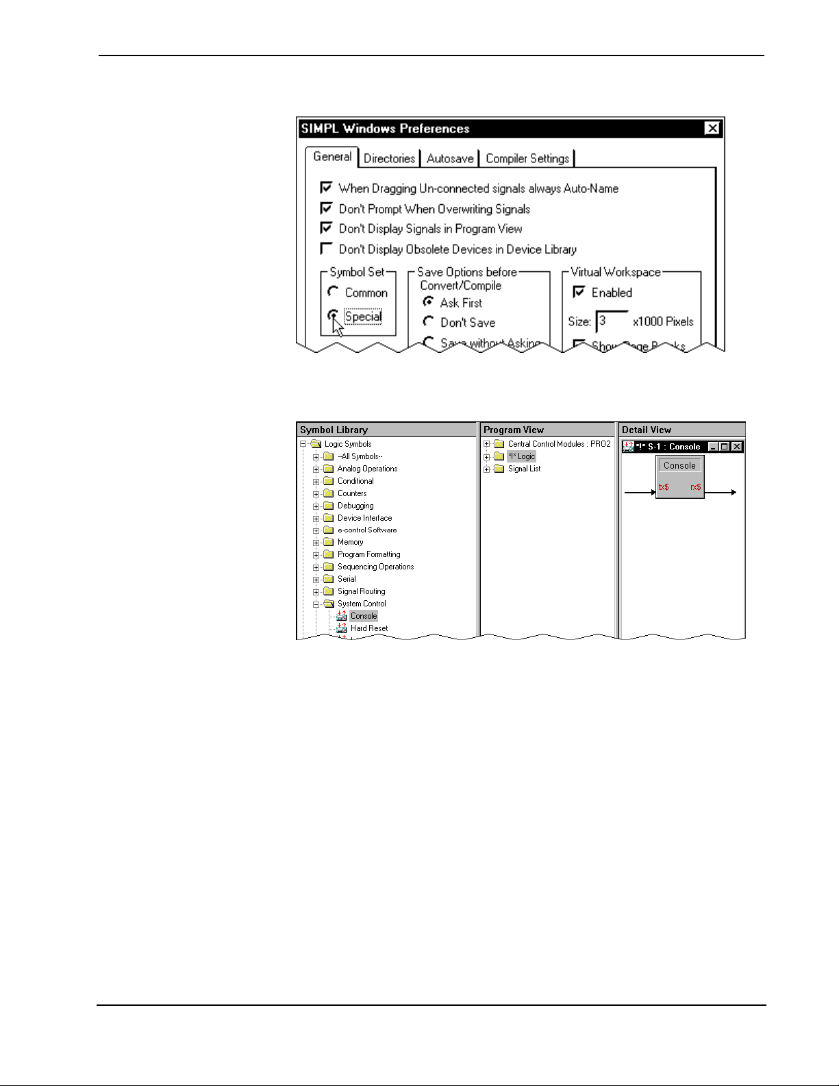
SIMPL Windows, select Edit | Preferences, which opens the "SIMPL Windows
Preferences" window. In the Symbol Set area of the General tab, select Special as
shown in the following diagram.
16 • 2-Series Control Systems Reference Guide – DOC. 6256A
Page 21
Crestron 2-Series Control Systems Reference Guide
“SIMPL Windows Preferences” Window
After enabling viewing of special symbols, the Console symbol can be viewed as
shown in the following diagram.
The Console Logic Symbol in SIMPL Windows
When the program sends data on the TX$ signal of the Console symbol, the control
system interprets the console command just as if it was received via the RS-232 or
Ethernet console and outputs a serial string to the RX$ signal of the console symbol
which can be programatically interpreted.
User Program Commands Symbol
Use the User Program Commands symbol to send data typed at the console to the
program. This feature is available for advanced programmers of SIMPL Windows.
The User Program Commands logic symbol only appears in the System Control
folder in the Symbol Library, after enabling a special symbol set for display. To
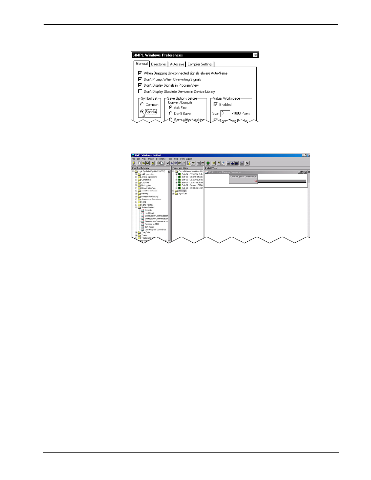
enable this set while in SIMPL Windows, select Edit | Preferences, which opens the
"SIMPL Windows Preferences" window. In the Symbol Set area of the General tab,
select Special as shown in the following diagram.
Reference Guide – DOC. 6256A 2-Series Control Systems • 17
Page 22
Reference Guide Crestron 2-Series Control System
“SIMPL Windows Preferences” Window
After enabling viewing of special symbols, the Console symbol can be viewed as
shown in the following diagram.
The User Program Commands Symbol in SIMPL Windows
The User Program Commands symbol receives data entered at the 2-Series console
prompt using the USERPROGCMD command. The syntax of the console command
requires double-quotes before and after the command string. The string may include
escape codes such as "\x".
The double quotes are stripped off and any escape codes are processed before
passing the string to the User Program Commands symbol. For example, if the user
types:
>USERPROGCMD "TURN ON DEBUG"
The string TURN ON DEBUG (without the double quotes) will be passed to the
User Program Commands symbol. The string can then be processed as desired.
Command Groups
Console commands are grouped logically. If the operator enters “help” from the
console, the 2-Series processor responds with a list of categories. It is possible to
find the same command in more than one category. Categories include:
• All – all 2-series console commands.
• Device – pertains to the unit itself.
• Ethernet – govern parameters that involve the Ethernet port(s).
• File – influence the internal file system.
• System – sets system-wide parameters.
18 • 2-Series Control Systems Reference Guide – DOC. 6256A
Page 23

Crestron 2-Series Control Systems Reference Guide
Commands are case insensitive and can be entered from the appropriate prompt (i.e.,
AV2, PRO2, DVP4DI, etc.). Help on individual commands is available by typing the
command followed by a "?" (i.e., ADDMASTER ?). The following table lists
acceptable commands alphabetically and provides a brief description of each
command. Refer to “Appendix C: Console Command Listing” on page 91 for
detailed information.
NOTE: The commands listed are not applicable to every processor. Refer to
“Appendix C: Console Command Listing” on page 91 to determine if the command
is applicable to your processor.
List of Acceptable Commands for the 2-Series Dual Bus Control System
COMMAND DESCRIPTION
ADDDNS Add a DNS server to the static list
ADDMASTER Add an entry to IP table to act as a master to the current system
ADDPORTMAP Add a port map to the NAT table
ADDSLAVE
AUTONEGOT Set auto negotiation for Ethernet device
BROADCAST Enable/disable the broadcasting of error messages
BYE Close user session
CALTOUCH Start DVP4 touchscreen calibration
CARDS Display cards detected in system
CD Change the file directory
CFAUTORUN
CFLOGERR Enable logging errors to compact flash
CFPROJDIRS Display a list of project directories on compact flash
CFTRANSFER Transfer a project to/from compact flash
CIPPORT Specify the port for the CIP interface
CLEARERR Clears the current error log
CNETID Set the Cresnet ID of the system
COMPACT Remove invalid files from system
COMCONSOLEMODE Sets operating mode of COM B
CTPPORT Specify the port for the CTP console
CURSOR Set the cursor option for the DVP4
DEFROUTER Set default router
DELETE Delete file(s)
DHCP Enable/disable dynamic IP address via DHCP
DIR Display files in directory
DOMAINNAME Enter a domain name to be used in DHCP
ECHO Enable/disable character echoing
EEPROM Displays the parameters stored in EEPROM
ERRLOG Prints the current error log
ESTATUS Displays the status and parameters for the Ethernet card
ETHERNET Enable/disable Ethernet
ETHERTEST Perform diagnostic test on the Ethernet card
FPPASSWORD Set front panel password
FREE Show available file space
GETCODE Retrieve the code needed for e-Control2 activation
GETFPLINE Show LCD front panel display on the console
HEAPFREE Show available RAM space
HELP Display help screens
Add an entry to IP table to act as a peer or slave to the current
system
Enables an automatic start of programs when compact flash is
inserted or extracted
(continued on next page)
Reference Guide – DOC. 6256A 2-Series Control Systems • 19
Page 24

Reference Guide Crestron 2-Series Control System
List of Acceptable Commands for the 2-Series Dual Bus Control System (Continued)
COMMAND DESCRIPTION
HOSTNAME Set the host name to be used in a DNS/DHCP environment
I2CERROR Enable reporting of I2C errors
ICMP Enable/disable response to ICMP ping requests
INFO Print software capabilities
INITIALIZE Clear internal file system
INPUT Set the DVP4 input resolution
IPADDRESS Set IP address
IPMASK Set IP subnet mask
IPTABLE Display IP table
ISDIR Check to see if path is a directory
KILLSOCKET Terminate a TCP console connection
LISTDNS Displays a list of DNS servers
MAKEDIR Create a file directory on compact flash
MESSAGE Display a message on front panel screen
MODEMINITSTRING Displays and changes the modem initialization string
NATENABLE Enable/disable Network Address Translator (NAT)
NATREMOTE
NPA Access Network Poll Accelerator Utilities
NVRAMCLEAR Clear the program portion of NVRAM
NVRAMDISK Establish and format a file disk in NVRAM
NVRAMGET Retrieve the contents of NVRAM using XMODEM from the system
NVRAMPUT Load the contents of NVRAM using XMODEM to the system
NVRAMREBOOT
OUTPUT Set the DVP4 output resolution
PASSWORD Set console password
PING Perform IP ping test on remote node
PROGRESET Reloads and restarts the program
PROGUPTIME Display the amount of time the program has been running
RAMFREE Show available file space in the ram file system
REBOOT Perform system reboot
REMDNS Remove a DNS server from the list
REMMASTER Remove a master entry from IP table
REMOVEDIR Delete a file directory on compact flash
REMPORTMAP Remove a port map from the NAT table
REMSLAVE Remove a peer/slave entry from the IP table
REPORTCRESNET Show all devices on the main Cresnet leg
RESTORE Restore factory defaults
RTSCTS Set/clear hardware handshaking
SAVEPARAM Save system parameters
SDEBUG Monitor packets to/from logic
SECURECIPPORT Set the secure (SSL) port for CIP
SECURECTPPORT Set the secure (SSL) port for CTP
SECUREWEBPORT Set the secure (SSL) webserver port
SELFTEST Initiate the self test procedure
SENDKEY Add e-Control2 activation key
SENDMODEMINITSTRING Sets/clears modem initialization
SERIAL Set serial communication parameters
SETUP Enter the DVP4 setup pages
Enable/disable configuring the Network Address Translator (NAT)
from the WAN (LAN A) port
Enables/disables storing special reboot information when the
processor unexpectedly reboots.
(continued on next page)
20 • 2-Series Control Systems Reference Guide – DOC. 6256A
Page 25

Crestron 2-Series Control Systems Reference Guide
List of Acceptable Commands for the 2-Series Dual Bus Control System (Continued)
COMMAND DESCRIPTION
SHOWEXTRAERRORS Enables extended error reporting
SHOWHW Display hardware configuration
SHOWPORTMAP Display the portmap from the NAT table
SSL Configure the SSL options
STANDBY Put the DVP4 into standby mode
STBYTO Set the standby timeout for DVP4
SYSTEM Xmodem download new firmware
TELNETPORT Enable/disable connections on the Telnet port (23)
TESTDNS Perform a DNS lookup on a given name
TIMEDATE Set the time and date
TOUCH Set the touch input for a DVP4
TYPE Display file contents
UPLOAD Load file into cresnet device
UPTIME Display the amount of time the system has been running
USERPROGCMD Send a string from the console to the user program
USERPASSWORD Enter the password to protect user pages
VERSION Print version to console
WEBINIT Initialize Webserver default file
WEBPORT Specify the port for the Webserver
WEBSERVER Enable/disable Webserver
WHO Display a list of the active console and gateway connections
XGETFILE Use Xmodem to retrieve file from system
XONXOFF Set/clear software handshaking
XPUTFILE Use Xmodem to transfer file to ROM
Processor Groups
At the time this document was released, Crestron offered 14 different 2-Series
processors. Selection of a processor depends on the application of the system.
Commands may only be supported on a ‘subset’ of 2-Series processors or processor
group. The table below lists the specific processors that belong to a processor group.
Breakdown of Processor Groups
PROCESSOR GROUP SPECIFIC PROCESSORS*
All 2-Series Processors
Audio Processors MP2 and MP2E
Ethernet Processors
Dual Ethernet Processors PRO2, AV2, PAC2, and RACK2
Compact Flash Processors PRO2, AV2, PAC2, RACK2, CNX-DVP4, and C2N-DVP4DI
Cresnet Processors
Display Processors CNX-DVP4 and C2N-DVP4DI
Plug-in Card Processors PRO2, AV2 (with card cage), PAC2, and RACK2
Front Panel Processors PRO2 and RACK2
QuickMedia Processors QM-RMC and QM-RMCRX(-BA)
* While not considered a 2-Series processor, there are console commands that can only be used when
a C2N-NPA8 is attached to the control system.
PRO2, AV2, PAC2, RACK2, CP2, CP2E, MP2, MP2E, MC2W,
MC2E, CNX-DVP4, C2N-DVP4DI, QM-RMC, and
QM-RMCRX(-BA)
PRO2, AV2, PAC2, RACK2, CP2E, MP2E, CNX-DVP4, C2NDVP4DI, QM-RMC, and QM-RMCRX
PRO2, AV2, PAC2, RACK2, CP2, CP2E, MP2, MP2E, MC2W,
MC2E, CNX-DVP4, C2N-DVP4DI, and QM-RMCRX(-BA)
Reference Guide – DOC. 6256A 2-Series Control Systems • 21
Page 26

Reference Guide Crestron 2-Series Control System
Command Structure
Details about each of the acceptable commands that can be interpreted by the
2-Series Dual Bus Control System can be found in “Appendix C: Console Command
Listing” on page 91. Commands are listed alphabetically. Each listing includes a
description of the command, a list of help menus that contain the command, the
proper syntax for entering the command, definitions of parameters that may be
included in the syntax, a list of possible sources
CUZ with which the command is recognized by the processor, and the specific
processor group
2
that supports the command. For a description of each detail listed
for a given command, refer to the SAMPLE COMMAND table shown below.
1. Possible sources refers to the methods by which console commands are delivered to the control
system, as explained on page 16.
2. Processor groups are defined in more detail with “Processor Groups” on page 21.
SAMPLE COMMAND
Description: Provides a textual description of the command.
Help Menu(s): Provides the category, which is used with the console HELP command.
Syntax: Provides the text characters required to execute the command.
Parameters: Provides a description of each parameter used in the syntax.
Possible Source: Indicates the method of console connection used for the sample command. Connection methods include:
RS-232 - a Crestron Toolbox connection to the computer port of the 2-Series processor.
CTP - an Ethernet connection to port 41795 at the IP address of the 2-Series processor.
Telnet - an Ethernet connection to port 23 at the IP address of the 2-Series processor.
User Program - a command entered using the SIMPL Windows Console symbol.
Secure CTP - SSL connection to port 41797 at the IP address of the 2-Series processor.
Minimum CUZ: Indicates the first version of firmware that supported the command. CUZ is the extension name for the
Processor Group: Since the 2-Series line has such a diverse feature set, some processors may not support all the
zipped file that holds the updated operating system for the 2-Series processor. As new features or
improvements are developed, the capabilities of the operating system are enhanced and the changes
are reflected in a later CUZ version number.
commands. This detail indicates the group to which the command belongs. Refer to the table in
”Processor Groups" on page 21 of this guide for the specific processors that belong to a processor
group.
1
for the command, the minimum
22 • 2-Series Control Systems Reference Guide – DOC. 6256A
Page 27

Crestron 2-Series Control Systems Reference Guide
2-Series Memory & Directory Structure
Introduction
A 2-Series control system has 36MB of built-in memory (non-volatile and volatile).
The following diagram illustrates the memory structure of the 2-Series Control
System.
2-Series Memory Structure
32 MB SDRAM Volatile Memory
256 kB NVRAM
1.5 MB of operational memory
(CUZ file)
2.5.MB of Non-Volatile Memory
(SIMPL program storage, web files,
accessible directory structure)
The total of 36MB is specified as follows: 4MB flash (non-volatile), 32MB SDRAM
(volatile), and 256KB NVRAM (battery backed up). Flash memory contains the file
system inside the 2-series control engine. Non-volatile memory contains information
that is retained after the loss of electrical power. Volatile memory is lost after a
power failure. Refer to the lists below for a breakdown of memory usage for
program-related information stored in the unit.
Expandable to 4GB using flash
card
Flash
1. SIMPL Program
2. SIMPL+ Modules
3. Operating System (.cuz file)
Reference Guide – DOC. 6256A 2-Series Control Systems • 23
Page 28

Reference Guide Crestron 2-Series Control System
The 4MB flash memory consists of approximately 1.5MB used for firmware (.cuz
file), and approximately 2.5MB available for the SIMPL program and SIMPL+
modules. The files that reside in flash conform to a flat directory structure. The
following table presents the structure of the overall file system.
The directory structure of the 2-series control system can be broken down into two
parts. The first part resides on the on-board flash memory (and discretionary
NVRAM memory when the NVRAMDISK option is enabled) and the second resides
on the optional external compact flash/microdrive card. Programs, data files, and
data can be stored in the on-board flash or on the compact flash card (if installed).
This section briefly describes the structure of the file system.
The files that reside in the internal flash/NVRAM conform to a flat directory
structure while the compact flash system contains a fully FAT32 compatible file
system to allow the same compact flash card to be used in a Windows environment.
The table, shown after this paragraph, presents the structure of the overall file
system.
Control System Directory Structure
TOP LEVEL SECONDARY LEVEL DESCRIPTION
\ Root of the file system
DISPLAY
SYS Contains various system configuration files
SETUP Directory for NAT configuration Web pages
HTML Web pages
SIMPL Control system program files
SPLUS SIMPL+ module files
USER Used for user-defined files
MAILBOX Directory contains the user mailbox file
CF0
NVRAM NVRAM disk is enabled
Legacy directory used in Crestron Isys® panels
to hold display lists
The mounting point for the compact flash files;
the 0 (or zero) refers to the on-board compact
flash slot
Although the file system names are case insensitive, the case is preserved to maintain
file checksums. The compact flash directory only appears when a compact flash card
is inserted into the system. The NVRAM directory only appears if an NVRAM disk
has been created. To reference files on the compact flash, prefix the “\CF0\” to any
fully qualified path from the Windows environment. For example, if the file in
Windows is “\MyDirectory\MySubdirectory\MyFile.ext”, the complete 2-Series path
for a file on the first compact flash slot (onboard) is:
“\CF0\MyDirectory\MySubdirectory\MyFile.ext”
When the SIMPL Windows program is stored on the compact flash, the files reside
in the directories \CF0\SIMPL and \CF0\SPLUS. When web pages are stored on the
compact flash, the directory is \CF0\HTML. Storing the program or web pages on
the compact flash gives those files precedence over files stored on internal flash.
That is to say, if you have different programs stored in both internal flash and
compact flash, the program on compact flash runs at boot-up.
Non-volatile (NVRAM)
1. SIMPL+ Variables (Default if no options are specified, or using
"nonvolatile" qualifier or #DEFAULT_NONVOLATILE)
24 • 2-Series Control Systems Reference Guide – DOC. 6256A
Page 29

Crestron 2-Series Control Systems Reference Guide
2. Signals explicitly written to NVRAM (by symbols such as Analog
RAM, Analog RAM from database, Serial RAM, Serial RAM from
database, Analog Non-volatile Ramp, Digital RAM, etc.)
Volatile (SDRAM)
1. Digital, analog and serial signal values
2. SIMPL+ Variables (if "volatile" qualifier is used, or
#DEFAULT_VOLATILE is used)
DRAM is used by the operating system for dynamic storage of variables, signals and
other constructs used at runtime. The actual amount of DRAM used at any given
time depends on the particular program that is running, i.e., usage is variable, or
dynamic, during normal operation.
NOTE: SDRAM is internal to operations and is not available to the programmer.
Non-Volatile Random Access Memory (NVRAM)
Disk
2-Series control systems are equipped with Non-Volatile Random Access Memory
(NVRAM). NVRAM contains information that is retained after the loss of electrical
power. Information that can be stored in NVRAM includes:
• SIMPL+ Global Variables (using "nonvolatile" qualifier or
#DEFAULT_NONVOLATILE)
• Signals explicitly written to NVRAM (by symbols such as Analog RAM,
Analog RAM from database, Serial RAM, Serial RAM from database,
Analog Non-volatile Ramp, Digital RAM, etc.)
• Portions of the NVRAM may be set aside for implementing an “NVRAM
Disk”. This can be used to provide file system access from SIMPL+.
NOTE: NVRAM values are position sensitive in the program. When saving the
NVRAM is crucial to your application, it is recommended to place all symbols and/or
modules that use NVRAM at the beginning of the program. When NVRAM (.nvr file)
is restored, all the values should line up with the program. If the program is modified,
and new logic that uses NVRAM is placed before any older symbols using NVRAM,
the previously stored values will not line up and presets will have to be re-entered. To
avoid concerns regarding the position of values within NVRAM, values can be stored
on a file on the NVRAM disk by writing a SIMPL+ module to read and write the
values to the file.
Setting Up an NVRAM Disk
Use Crestron Toolbox to set up a NVRAM disk on the processor. NVRAM disk
provides compact flash (CF) type file storage on systems without a CF slot. It also
works on systems with CF. The NVRAM disk’s storage capacity is limited in size.
Any space allocated to the NVRAM disk is not accessible by the SIMPL Windows
NVRAM symbols or SIMPL+ non-volatile variables.
Reference Guide – DOC. 6256A 2-Series Control Systems • 25
Page 30
Reference Guide Crestron 2-Series Control System
To set up an NVRAM disk, perform the following.
1. Open Crestron Toolbox and establish communications with the control
system as described on page 5.
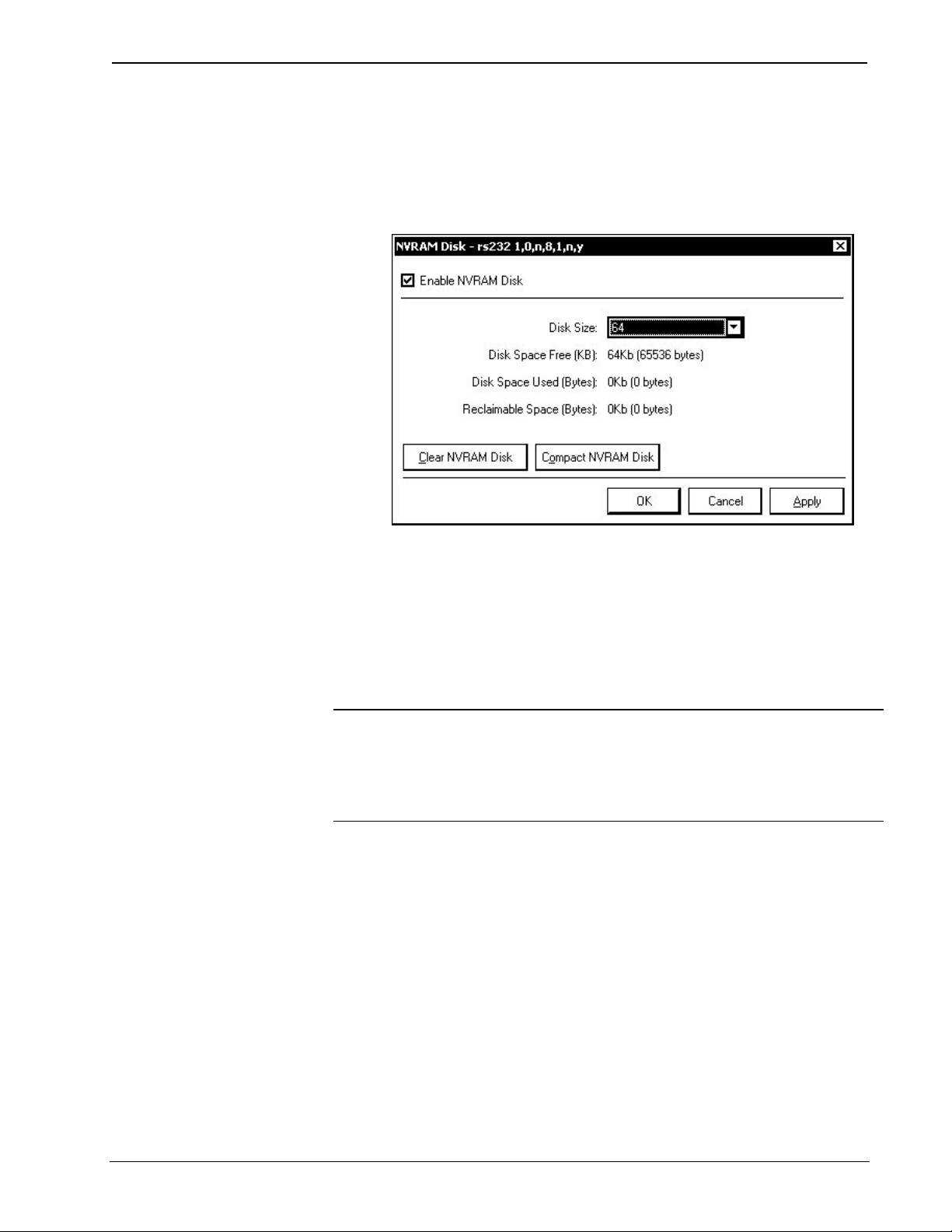
2. Select Functions | NVRAM Disk… to open the “NVRAM Disk” window.
“NVRAM Disk” Window
3. Enable the NVRAM Disk by selecting Enable NVRAM Disk.
4. Select the size of the NVRAM Disk.
5. Click OK or Apply to create the NVRAM Disk.
Files stored in NVRAM disk are accessed in the \NVRAM directory of the file
system. Entering the command without a parameter displays the current setting.
Each time the NVRAMDISK is enabled, the contents of the NVRAM disk are wiped
clean.
NOTE: The NVRAMDISK function (available in CUZ files later than 3.030), will fail
unless it can determine the amount of NVRAM used by the program, to ensure that the
NVRAM is not overwritten. Programs compiled in SIMPL Windows version 2.04.11
or later can provide this information. In the event of a failure of the NVRAMDISK
command, ensure that your program has been recompiled in an appropriate version of
SIMPL Windows and reloaded.
For more information on the NVRAMDISK command and other NVRAM-related
functions, refer to “Appendix C: Console Command Listing” on page 91.
Retrieving NVRAM Files from the NVRAM Disk
NVRAM files can be retrieved from the processor and saved to a local disk. To
retrieve NVRAM data from the processor and save to a file:
1. Open Crestron Toolbox and establish communications with the control
system as described on page 5.
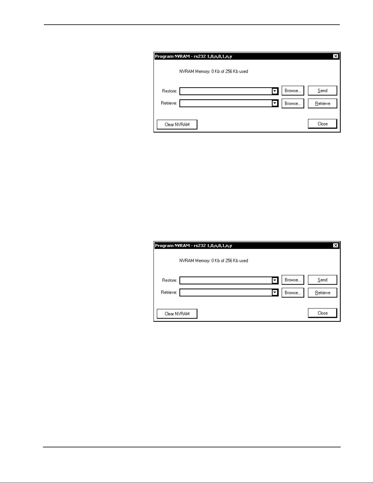
2. Select Functions | Program NVRAM… to open the “Program NVRAM”
window.
26 • 2-Series Control Systems Reference Guide – DOC. 6256A
Page 31
Crestron 2-Series Control Systems Reference Guide
“Program NVRAM” Window
3. Click the Browse button next to the Retrieve button and specify the name
and location of the file to be saved.
4. Click Retrieve. A status bar will display the progress of the file transfer.
Restoring NVRAM Files to the Control System
NVRAM files can be restored to the control system from a saved file. To restore
NVRAM data to the control system from a saved file:
1. Open Crestron Toolbox and establish communications with the control
system as described on page 5.
2. Select Functions | Program NVRAM… to open the “Program NVRAM”
window.
“Program NVRAM” Window
3. Click the Browse button next to the Send button and specify the name and
location of the file to be restored.
4. Click Send. A status bar will display the progress of the file transfer.
NVRAMREBOOT
When a control system unexpectedly reboots, the error that caused the reboot is not
stored to the error log since the log is erased when the control system reboots.
However, the information contained in the error log can be written to NVRAM by
using the NVRAMREBOOT command.
To use NVRAMREBOOT:
1. Use Crestron Toolbox to establish communications with the control system
as described on page 5.
Reference Guide – DOC. 6256A 2-Series Control Systems • 27
Page 32

Reference Guide Crestron 2-Series Control System
2. Open a text console window and type NVRAMREBOOT ON. This
command will write messages created during rebooting to NVRAM. If an
anomaly exists, this command will save the error even though the control
system has rebooted.
3. To view the contents of NVRAM, retrieve the file from NVRAM as
described in “Retrieving NVRAM Files from the NVRAM Disk” on page
26 and open the error log as described in “Viewing Error Messages with
Crestron Toolbox” on page 30. After the error log has been captured, turn
off the NVRAMREBOOT command by typing NVRAMREBOOT OFF.
Running Programs from Compact Flash
Certain 2-series control systems are equipped with a compact flash slot. On powerup or a hardware reset (HW-R), the control system first checks for a program on
compact flash (if installed) and then internal flash.
Crestron Toolbox can be used to control the actions of the control system when a
compact flash card is inserted into a running system.
To determine how the control system operates with a compact flash card installed:
1. Open Crestron Toolbox and establish communications with the control
system as described on page 5.
2. Select Functions | Compact Flash to display the “Compact Flash”
window.
“Compact Flash” Window
3. Click the Enable Auto-Run check box to enable the Auto-Run mode.
When operating in the Auto-Run mode, the control system will
automatically reset and run the Compact Flash program when the Compact
Flash card is inserted into the CF slot. If the Compact Flash is removed, the
program in internal Flash will automatically run.
When auto-run mode is disabled, a Program Reset must be sent to the
control system after the Compact Flash card is inserted or removed to run
the program.
4. Click OK or Apply for changes to the Auto-Run mode to take effect.
NOTE: Control systems are shipped with the Auto-Run mode enabled by default.
28 • 2-Series Control Systems Reference Guide – DOC. 6256A
Page 33

Crestron 2-Series Control Systems Reference Guide
2-Series Control System Error Messages
Introduction
This section provides a brief description of 2-Series error messages that one may
encounter. Error messages may be the result of hardware or software failure,
hardware incompatibility with software definitions, or a programming error. An error
is indicated by the MSG / ERR LED on the front panel of the control system.
Error messages created by the control system are written to an error log that is stored
in the control system’s RAM. If power is recycled or the processor is rebooted, the
error log will be erased. The error log can be saved to a compact flash card on
processors that can use a compact flash card.
NOTE: To save the error log in non-volatile memory, use the NVRAMREBOOT
console command to have the error log write to NVRAM. For more information,
refer to “NVRAMREBOOT” on page 27.
There are two ways to display the error log. Either use the front panel (if the 2-Series
control system is equipped with one) or use Crestron Toolbox.
Viewing Error Messages with the Front Panel
The front panels of select 2-Series control systems incorporate a reverse mode
(yellow on black) LCD screen, shown below. Access the error log by pressing the
MSG menu function button on the Main Menu (default LCD display).
Front Panel Displaying Main Menu
As shown in the sample below, the top line of the LCD screen provides a single error
message from the error log. The message indicates that the system expects a card to
be inserted into slot 1. The bottom line of the LCD screen provides commands. The
user can use NEXT or PREV to scroll through the entire error log. Some messages
may be too long to be displayed across the top line of the LCD screen; use << and
>> to scroll left and right, respectively.
The CLEAR button can to used to empty the error log and extinguish the MSG /
ERR front panel LED. A security message prompts the user to confirm the
command.
MSG Submenu with Sample Message
Reference Guide – DOC. 6256A 2-Series Control Systems • 29
Page 34

Reference Guide Crestron 2-Series Control System
Viewing Error Messages with Crestron Toolbox
Crestron Toolbox can be used with any 2-Series control system to view messages
stored in the error log.
To manage the Error Log with Crestron Toolbox:
1. Open Crestron Toolbox and establish communications with the control
system as described on page 5.
2. Select Functions | Error Log to open the “Error Log” window.
“Error Log” Window
The “Error Log” window opens with the latest version of the error log on
the control system.
To refresh the error log, click Retrieve Error Log from Device.
To clear the error log, click Clear Error Log in Device. The MSG / ERR
LED on the front panel (if present) will extinguish.
To save the error log, click Save As…, select a filename and directory, and
click OK.
To retrieve a saved error log, select Open…, select the file to be opened,
and click OK.
30 • 2-Series Control Systems Reference Guide – DOC. 6256A
Page 35

Crestron 2-Series Control Systems Reference Guide
Error Levels
The following table lists and defines the four levels of error messages that may
appear.
Error Message Levels
TYPE DEFINITION
Notice An event has occurred that is noteworthy, but will not affect program operation.
Warning An event has occurred that could affect program operation, but the program can
Error An event has occurred that indicates that the program is not operating as
Fatal An event has occurred that will prevent the program from running. The
The MSG/ERR LED on the front panel does not illuminate when Notice-level
errors occur.
still run normally. The MSG/ERR LED on the front panel will illuminate when a
Warning-level error occurs.
expected. The MSG/ERR LED on the front panel will illuminate when a Errorlevel error occurs.
MSG/ERR LED on the front panel will illuminate when a Fatal-level error occurs.
Error Format
Each error message has the following format:
Level: Message
Some messages have a suffix with additional information in parenthesis:
(Error#:Extended Error#:Reserved#)
Only the first two items (level and message) within the error format are of any
immediate value to the programmer.
• Level – defined on previous page.
• Message – varied and defined in “Appendix D: Error Message Definitions”
on page 123.
• Error# – unique identifier for Crestron use.
• Extended Error# – unique identifier for Crestron use.
• Reserved# – not yet defined; for future use.
NOTE: It is important to report the exact error message to a Crestron customer
service representative, as well as any Error# and Extended Error#. Also, try to be as
specific as possible regarding the events that lead to the error (i.e., pressing a certain
sequence of buttons, etc). Finally, provide the specific .cuz used.
For a detailed list of all error messages, refer to “Appendix D: Error Message
Definitions” on page 123.
Reference Guide – DOC. 6256A 2-Series Control Systems • 31
Page 36

Reference Guide Crestron 2-Series Control System
Master-Slave Modes
Introduction
Master-Slave mode is a network configuration that allows a Crestron 2-Series control
system to access ports on other Crestron 2-Series control systems over Cresnet or
Ethernet. By attaching a “slave” control system to a “master” control system, the
master control system can use ports it may not normally have (I/O, IR, RF, etc.).
In a master-slave environment, the master control system contains the SIMPL
Windows program that controls all Cresnet and Ethernet devices attached to it. The
slave control system turns off its processing capabilities and behaves exactly like any
other Cresnet or Ethernet device. It obeys the program in the master control system,
making its ports available for control by the master. By using slave systems, only
one master program has to be written to control multiple slave systems.
NOTE: If there is a need for a control system to run its own program but be able to
communicate with other control systems, use the Intersystem Communications
symbol for peer-to-peer communications between control systems over Ethernet or
serial communications. For more information on the Intersystem Communications
symbol, refer to the SIMPL Windows help file.
Depending on a control system’s communications capabilities, a control system may
function as a Cresnet master, a Cresnet slave, an Ethernet master, or an Ethernet
slave.
Definitions
Cresnet Master
When in the Cresnet master mode (the default mode for most control systems), a
master control system can control Cresnet and Ethernet devices (if equipped with
Ethernet capabilities) as well as control systems operating in the Cresnet slave mode.
Control systems with Cresnet and Ethernet capabilities can function as a Cresnet
master and Ethernet master simultaneously.
Cresnet Slave
A control system operating in the Cresnet slave mode operates as a Cresnet device
and makes its built-in ports (except for Cresnet and Ethernet) available to a master
control system. While operating in the Cresnet slave mode, any program that is
loaded into the control system will not run. When operating in Cresnet slave mode, a
control system can address any installed hardware, but it cannot address Cresnet or
Ethernet network devices.
Slave control systems with Cresnet and Ethernet abilities can be configured to
operate as either Cresnet or Ethernet slaves, not both. If a slave system is
accidentally configured as both, it will operate in the Cresnet slave mode.
Ethernet Master
When operating as an Ethernet master, a master control system can control Ethernet
and Cresnet devices (if equipped with Cresnet capabilities) as well as control
systems operating in the Ethernet slave mode.
32 • 2-Series Control Systems Reference Guide – DOC. 6256A
Page 37

Crestron 2-Series Control Systems Reference Guide
Control systems with Ethernet and Cresnet capabilities can function as an Ethernet
master and a Cresnet master simultaneously.
Ethernet Slave
A control system operating in the Ethernet slave mode operates as an Ethernet device
and makes its built-in ports (except for Ethernet and Cresnet) available to a master
control system. While operating in the Ethernet slave mode, any program that is
loaded into the control system will not run. When operating in the Ethernet slave
mode, the control system can address any installed hardware, but it cannot address
Cresnet or Ethernet network devices.
Slave control systems with Ethernet and Cresnet abilities can be configured to
operate as either Ethernet or Cresnet slaves, not both. If a slave system is configured
as both, it will operate in the Cresnet slave mode.
Master-Slave Operating Guidelines
Following are some general rules for master-slave configurations:
• A slave device cannot have its own network (Cresnet or Ethernet).
• 2-Series slave systems can only be controlled by a 2-Series master system.
• A control system with both Cresnet and Ethernet capabilities can operate as
an Ethernet master and a Cresnet master simultaneously.
• A control system with both Cresnet and Ethernet capabilities can be either
an Ethernet slave or a Cresnet slave. It cannot be both simultaneously. If it
is configured as both, it will operate in the Cresnet slave mode.
• A slave can be controlled by only one master control system. Only one
Cresnet master can exist in a network. Multiple Ethernet master systems can
exist in a network. However, an Ethernet slave only responds to one master.
• Any program loaded into a control system will not execute while a control
system is in the slave mode.
• While operating in the slave mode, Crestron Toolbox functions such as
firmware upgrades can still be performed. Passthrough mode operations
from Viewport can also be used on the slave control system.
NOTE: All control systems ship in the master mode except for the C2N-DVP4DI
and CNX-DVP4, which ship in the Cresnet slave setting.
Reference Guide – DOC. 6256A 2-Series Control Systems • 33
Page 38

Reference Guide Crestron 2-Series Control System
Configuring the Control System
System Requirements
To operate a control system as a master or slave device, the following control system
update files and programming software are required:
Software Requirements for Master-Slave Operations
SOFTWARE* VERSION NUMBER SUPPORTED MODES
2-Series Control
System Update Files
AV2
C2N-DVP4DI
CNX-DVP4
CP2
CP2E
MC2E
MC2W
MP2
MP2E
PAC2
PRO2
QM-RMC
QM-RMCRX(-BA)
RACK2
SIMPL Windows
Crestron Toolbox Version 1.01.06 or later N/A
* The latest versions can be obtained from the Crestron website. Refer to NOTE which follows.
Version 3.044 or later
Version 3.060 or later
Version 2.006 or later
Version 3.044 or later
Version 3.044 or later
Version 3.050 or later
Version 3.050 or later
Version 3.050 or later
Version 3.050 or later
Version 3.044 or later
Version 3.044 or later
Version 3.052 or later
Version 3.052 or later
Version 3.044 or later
Version 2.04.11 with
library update 232 or
version 2.04.14 or later
Cresnet or Ethernet
Cresnet or Ethernet
Cresnet or Ethernet
Cresnet
Cresnet or Ethernet
Cresnet or Ethernet
Cresnet
Cresnet
Cresnet or Ethernet
Cresnet or Ethernet
Cresnet or Ethernet
Ethernet
Cresnet or Ethernet
Cresnet or Ethernet
N/A
NOTE: Crestron software and any files on the website are for Authorized Crestron
dealers and Crestron Authorized Independent Programmers (CAIP) only. New users
may be required to register to obtain access to certain areas of the site (including the
FTP site).
Cresnet Master-Slave Modes
Every device (including a control system) is assigned a unique Cresnet ID (Net ID).
Master control systems always use Net ID 02. If a control system is to be used as a
slave device, its Net ID must be changed to a hexadecimal value ranging from 03 to
FE.
Use Crestron Toolbox to establish communications between the control system and
your PC as described on page 5. After establishing communications, Crestron
Toolbox can be used to set the Net ID and change a control system from a master
system to slave device, and back.
Cresnet Master Mode
After establishing communications with the control system, select Functions |
Cresnet ID… to open the “Cresnet ID” window.
34 • 2-Series Control Systems Reference Guide – DOC. 6256A
Page 39

Crestron 2-Series Control Systems Reference Guide
“Cresnet ID” Window
Select Cresnet ID 02 to set the control system to the Cresnet Master mode and click
OK or Apply. The control system will automatically reboot.
NOTE: The control system must be detached from Cresnet before changing a slave
to a master.
NOTE: If a control system is operating in the Cresnet Master mode, the Device IDs
section of the “System Information” window will indicate a Cresnet ID value of 02.
NOTE: Only one Cresnet master control system can exist in a network.
Cresnet Slave Mode
After establishing communications with the control system, select Functions |
Cresnet ID… to open the “Cresnet ID” window.
“Cresnet ID” Window
Select any Cresnet ID from 03 to FE to set the control system to the Cresnet Slave
mode and click OK or Apply. The control system will automatically reboot.
NOTE: The control system must be detached from Cresnet before changing the
master to a slave.
NOTE: If a control system is operating in the Cresnet Slave mode, the Product Info
section of the “System Information” window will indicate the control system as a
“Cslave”. The Device IDs section of the “System Information” window will indicate
Reference Guide – DOC. 6256A 2-Series Control Systems • 35
Page 40

Reference Guide Crestron 2-Series Control System
the new Cresnet ID value. The Program Info section is not displayed as the slave
control system does not have a program that is running.
Ethernet Master-Slave Modes
The contents of a control system’s IP table and SIMPL Windows programming
determine whether a control system is operating as a master control system or a slave
device. If a control system’s IP table entry lists a “master” device, the control system
is operating in the Slave mode to the master control system listed in the IP table. For
more information on IP table entries, refer to the latest revision of the Crestron
e-Control
Crestron website.
Use Crestron Toolbox to make changes to a control system’s IP table.
To view a control system’s IP table, establish communication with the control
system as described on page 5 and select Functions | IP Table Setup… to open the
“IP Table” window.
“IP Table” Window
®
Reference Guide (Doc. 6052) which can be downloaded from the
Ethernet Master Mode
To designate a control system as an Ethernet master, there must be no “master”
entries in the control system’s IP table. Removing a master entry automatically
configures a control system as an Ethernet master when it reboots (unless it is also
configured as a Cresnet slave). Refer to the previous diagram for a sample IP table of
a master control system.
The IP IDs listed above can represent Ethernet devices and Ethernet slave devices.
Ethernet Slave Mode
To designate a control system as an Ethernet slave, there must be an entry for a
“master” control system in the Ethernet slave’s IP table. Once a master control
system is listed in the slave’s IP table, other entries are ignored, as a slave device
cannot have its own network. Refer to the following diagram for a sample IP table on
a slave control system.
36 • 2-Series Control Systems Reference Guide – DOC. 6256A
Page 41

Crestron 2-Series Control Systems Reference Guide
Slave Control System’s IP Table
NOTE: The slave device’s IP table can only be loaded into the slave device through
Crestron Toolbox with a PC directly connected to the slave control system. SIMPL
Windows cannot override the slave device’s IP table when loading a program onto a
master control system.
NOTE: If a control system is operating in the Ethernet Slave mode, the Product
Info section of the “System Information” window will indicate the control system as
a “Eslave”. The Program Info section is not displayed as the slave control system
does not have a program that is running.
NOTE: After changing the IP table, the control system will reboot.
Configuration and Programming
Use SIMPL Windows to configure master-slave relationships between control
systems in a network and to program the master control system using slave devices.
NOTE: Each port on the master and slave system that requires configuration must
be individually configured. In our example, a COM port on Slot 6 of the slave
system must be configured separately from any COM port on Slot 4 of the master
system.
Configuring a Control System as a Master Control System
There are no special SIMPL Windows procedures for configuring a control system to
operate in the master mode.
NOTE: If Ethernet slave devices are to be added, an Ethernet port must be present
on the master control system.
Configuring a Control System as a Cresnet Slave Device
To incorporate a control system as a Cresnet system slave, drag the Remote Cresnet
Processing symbol for the control system to be added from the Cresnet Control
Modules | Cresnet Remote Processing Modules folder of the Device Library and
drop it in the System Views. In this example, we are using a PRO2 as the master and
an MP2E as a slave device. The PRO2 System Views shows the MP2E as a slave
device in slot 9 with its default Net ID (assuming that no other C2Net devices are
present as shown in the following illustration). A slave control system must have a
Net ID of 03 or higher to be a slave device.
Reference Guide – DOC. 6256A 2-Series Control Systems • 37
Page 42

Reference Guide Crestron 2-Series Control System
C2Net-Device
Setting the Net ID in Device Settings
NOTE: Each Cresnet device has a unique Net ID in the program. If the Net ID is in
use by another device, SIMPL Windows will look for an available Net ID starting at
03.
Double-click the MP2E icon to open the “Device Settings” window. This window
displays the MP2E device information. If necessary, select the Net ID tab to change
the Net ID, as shown in the following figure.
“Device Settings” Window for the MP2E
NOTE: SIMPL Windows automatically changes Net ID values of a device added to
a program if a duplicate device or a device with the same default Net ID already
exists in the program. Always ensure that the hardware and software settings of the
Net ID match. For Net ID hardware settings details, refer to “Cresnet Slave Mode”
on page 35.
38 • 2-Series Control Systems Reference Guide – DOC. 6256A
Page 43

Crestron 2-Series Control Systems Reference Guide
Expand the device to view the available slots in the MP2/MP2E remote processing
symbol. The following diagram shows the available slots of an MP2E operating in
slave mode.
Device Detail
NOTE: The C2Net-Device and C2ENET-Device slots are never available on a
control system operating in slave mode. All other slots may be configured as
described in the slave system’s respective manual. Slave devices do not control
networks.
Configuring a Control System as an Ethernet Slave Device
Continuing with our PRO2 example, add an Ethernet card to the Z-Bus by rightclicking slot 8. Select Add item to: “C2Z Card Slot” and add a C2ENET-1 or
C2ENET-2 as shown in the following diagram.
Adding a C2ENET Card
To incorporate a control system as an Ethernet system slave, drag the Remote
Ethernet Processing symbol for the control system to be added from the Ethernet
Control Modules | Ethernet Modules (Crestron) | Ethernet Remote Processing
Modules folder of the Device Library and drop it in the System Views.
The System Views shows the MP2E as a slave device in slot 8 with an IP ID of 50
(assuming that no other C2ENET devices are present as shown in the following
Reference Guide – DOC. 6256A 2-Series Control Systems • 39
Page 44

Reference Guide Crestron 2-Series Control System
illustration). The IP ID for the MP2E must be 03 or higher to be a slave device. The
IP ID must also match the IP ID set in the master control system’s IP table.
C2ENET Device
Setting the IP ID in Device Settings
Double-click the MP2E icon to open the “Device Settings” window. This window
displays the MP2E device information. If necessary, select the IP Net Address tab to
change the IP ID and other IP information, as shown in the following figure.
“Device Settings” Window for the MP2E
SIMPL Windows will create a default IP table based on the IP IDs assigned in
System View. If selected, the default IP table can be uploaded to the control system
after the SIMPL Windows program has been uploaded to the control system.
NOTE: SIMPL Windows automatically changes IP ID values of a device added to a
program if a duplicate device or a device with the same default IP ID already exists
in the program. Always ensure that the IP table listings on the slave device and
40 • 2-Series Control Systems Reference Guide – DOC. 6256A
Page 45

Crestron 2-Series Control Systems Reference Guide
software settings for the IP ID match. For IP ID hardware settings details, refer to
“Ethernet Slave Mode” on page 36.
Expand the device to view the available slots in the MP2/MP2E remote processing
symbol. The following diagram shows the available slots of an MP2E operating in
slave mode.
Device Detail
NOTE: Each Ethernet device has a unique IP ID in the program. If the IP ID is in
use by another device, SIMPL Windows will look for an available IP ID starting at
03.
NOTE: The C2Net-Device and C2ENET-Device slots are never available on a
control system operating in slave mode. All other slots may be configured as
described in the slave system’s respective manual. Slave devices do not control other
network devices.
Programming a Control System as a Master Control System
There are no special procedures for programming a control system that is operating
in the master mode. Refer to the control system’s Operations Guide for programming
instructions.
Programming a Control System as a Slave Device
The slots on a slave device are programmed as described in the slave device’s
Operations Guide.
Uploading
After completing the program in SIMPL Windows, upload the program to the master
control system. A slave device’s configuration information will be automatically
transferred by the master control system. Additionally, the default IP table can be
uploaded after the SIMPL Windows program has been uploaded to the control
system.
Reference Guide – DOC. 6256A 2-Series Control Systems • 41
Page 46

Reference Guide Crestron 2-Series Control System
Dynamic Host Configuration Protocol (DHCP)
Introduction
Crestron’s 2-Series control systems support DHCP (Dynamic Host Configuration
Protocol) in a Windows 2000 Server or Windows NT 4.0 Server environment.
When using DHCP, a dynamic IP address is automatically assigned to a device on
the network. These IP addresses are called “dynamic” because they are only
temporarily assigned, or leased, to the device. After a certain time they expire and
may change. When a device connects to the network (or the Internet) and its dynamic
IP address has expired, the DHCP server will assign it a new dynamic IP address.
The purpose of DHCP is to let network administrators centrally manage and
automate the assignment of IP addresses in an organization’s network. DHCP greatly
reduces the work necessary to administer a large IP network. Without DHCP, the
administrator has to manually configure the IP address each time a computer is
added to the network or moves to a different location.
DHCP provides integration with a DNS (Domain Name System) service. This
system allows hosts to have both domain name addresses (such as ftp.crestron.com)
and IP addresses (such as 65.206.113.4). The domain name address is easier for
people to remember and is automatically translated into the numerical IP address.
The domain name address (also called the Fully-Qualified Domain Name, or FQDN)
identifies the owner of that address in a hierarchical format: server.organization.type.
For example, ftp.crestron.com identifies the FTP server at Crestron, with “.com”
signifying a commercial organization.
A DNS server, also called a name server, maintains a database containing the host
computers and their corresponding IP addresses. Presented with the domain name
address ftp.crestron.com, for example, the DNS server would return the IP address
65.206.113.4.
Another name-resolution service is WINS (Windows Internet Naming Service).
WINS is used in conjunction with DNS and DHCP in a Windows NT 4.0 Server
environment.
Windows DHCP/DNS Server Configuration
Crestron’s 2-Series control systems (minimum CUZ 3.041) support DHCP in the
following environments:
• Windows 2000 Server with DHCP Server and DNS Server (Dynamic DNS
enabled)
• Windows NT 4.0 Server with DHCP Server and WINS Server
In the following configuration requirements, a scope defines the range of IP
addresses for the network. Typically a scope defines a single physical subnet on the
network. Scopes provide the primary way for the DHCP server to manage
distribution and assignment of IP addresses and any related configuration parameters
to clients on the network.
Scope options are client configuration parameters applied specifically to all clients
that obtain a lease within a particular scope. Some commonly used options include
IP addresses for default gateways (routers), WINS servers, and DNS servers.
42 • 2-Series Control Systems Reference Guide – DOC. 6256A
Page 47

Crestron 2-Series Control Systems Reference Guide
The network administrator should configure the Windows Server as follows:
Configuration 1: DHCP + Dynamic DNS (Windows 2000
only)
The network administrator should configure the DHCP scope to include the
following scope options:
• 003 - Router
• 006 - DNS Servers
• 015 - Domain Name
The DHCP scope should also have the following options enabled:
• Always dynamically update all nodes
• Enable updating of nodes that do not support dynamic DNS
The DNS Server should have the following option enabled:
• Enable WINS Resolution (Windows (NT 4.0)
• Enable WINS Forward Lookup (Windows 2000)
Configuration 2: DHCP + DNS + WINS (Windows NT 4.0 and
Windows 2000)
The network administrator should configure the DHCP scope to include the
following scope options:
• 003 - Router
• 006 - DNS Servers
• 015 - Domain Name
• 044 - WINS/NBNS Servers
• 046 - WINS/NBT Node Type (set value to “0x2”)
The DNS Server should have the following option enabled:
• Handle Dynamic Updates (Windows 2000 only)
Control System Configuration
1. Open Crestron Toolbox and establish communications with the control
system as described on page 5.
2. Select Functions | Ethernet Addressing… to open the “Ethernet
Addressing” window.
Reference Guide – DOC. 6256A 2-Series Control Systems • 43
Page 48
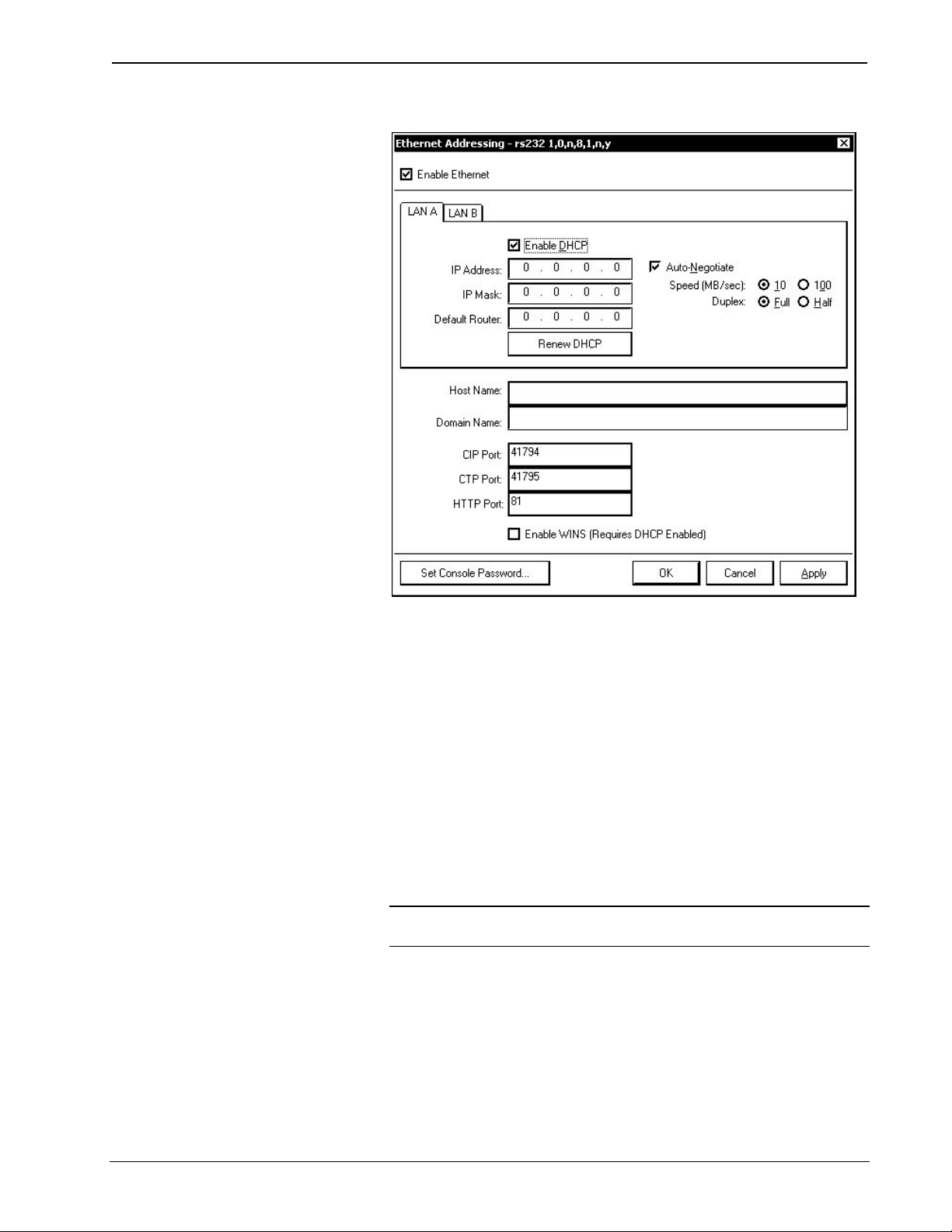
Reference Guide Crestron 2-Series Control System
“Ethernet Addressing” Window
3. Select the Enable DHCP check box to enable DHCP with Windows 2000
Server; for Windows NT 4.0 Server, select the Enable DHCP and the
Enable WINS check boxes. (The IP Address and IP Mask fields will be
ignored if either check box is selected.)
4. Enter the host name of the control system in the Host Name field. The
hostname identifies the control system on the network and is automatically
translated into the numerical IP address. The hostname can consist of up to
64 characters. Valid characters are 0 – 9, A – Z (not case-sensitive), and the
dash (hyphen character). No other characters are valid. The hostname
cannot begin with a dash or number.
5. If applicable, enter the domain in the Domain Name field. This is only
necessary if you are configuring DHCP on an Ethernet connection to a
control system that currently has a static address. The domain name will be
used to reconnect to the control system after it reboots. With a serial
connection, the domain does not need to be entered.
NOTE: The domain supplied by the DHCP server will overwrite the
domain that is indicated in this field.
6. Once all settings are made, click OK to store the settings and reboot the
control system.
Other Settings (optional):
You have the option to change the CIP and CTP port numbers in rare cases where a
network conflict may exist with ports 41794 and 41795.
The Web port can be changed for security reasons if no firewall or router is
44 • 2-Series Control Systems Reference Guide – DOC. 6256A
Page 49

Crestron 2-Series Control Systems Reference Guide
protecting the network. To prevent attacks by hackers the port can be moved to
another value. Users on the LAN would then have to specify the port number in the
URL, i.e., http//www.crestron.com:49153 where the value after the colon indicates
the Web port.
In most cases, the port numbers do not need to be changed.
Once the IP information for the control system has been set, it becomes possible to
communicate with the control system via TCP/IP.
Reference Guide – DOC. 6256A 2-Series Control Systems • 45
Page 50

Reference Guide Crestron 2-Series Control System
Secure Sockets Layer (SSL)
Introduction
Ethernet-enabled control systems provide built-in support for Secure Sockets Layer
(SSL), the de facto standard for protecting Web-based communication between
clients and servers. SSL is a protocol that provides a secure channel for
communication between two machines. The secure channel is transparent, which
means that it passes the data through, unchanged. The data is encrypted between the
client and the server, but the data that one end writes is exactly what the other end
reads. The SSL protocol uses TCP as the medium of transport.
SSL ensures that the connection between a Web browser and Web server is secure
by providing authentication and encryption. Authentication confirms that servers,
and sometimes clients, are who they say they are. Encryption creates a secure
“tunnel” between the two, which prevents unauthorized access to the system.
The secure tunnel that SSL creates is an encrypted connection that ensures that all
information sent between the client and server remains private. SSL also provides a
mechanism for detecting if someone has altered the data in transit. If at any point
SSL detects that a connection is not secure, it will terminate the connection and the
client and server will have to establish a new, secure connection.
SSL uses both public-key and symmetric-key encryption techniques. Public keys
are a component of public-key cryptographic systems. The sender of a message uses
a public key to encrypt data; the recipient of the message can only decrypt the data
with the corresponding private key. Public keys are known to everybody, while
private keys are secret and only known to the recipient of the message. Since only
the server has access to its private key, only the server can decrypt the information.
This is how the information remains confidential and tamper-proof while in transit
across the network.
An SSL transaction consists of two distinct parts: the key exchange, and the bulk
data transfer. The SSL Handshake Protocol handles key exchange and the SSL
Record Protocol handles the bulk data transfer.
The key exchange (SSL handshake protocol) begins with an exchange of messages
called the SSL handshake. During the handshake, the server authenticates itself to
the client using public-key encryption techniques. Then the client and the server
create a set of symmetric keys that they use during that session to encrypt and
decrypt data and to detect if someone has tampered with the data. Symmetric key
encryption is much faster than public-key encryption, while public-key encryption
provides strong authentication techniques.
Once the key exchange is complete, the client and the server use this session key to
encrypt all communication between them. They do this encryption with a cipher, or
symmetric key encryption algorithm, such as RC4 or DES. This is the function of the
SSL Record Protocol. There are two types of ciphers, symmetric and asymmetric.
Symmetric ciphers require the same key for encryption and decryption, whereas with
asymmetric ciphers, data can be encrypted using a public key, but decrypted using a
private key.
SSL supports a variety of ciphers that it uses for authentication, transmission of
certificates, and establishing session keys. SSL-enabled devices can be configured to
support different sets of ciphers, called cipher suites.
46 • 2-Series Control Systems Reference Guide – DOC. 6256A
Page 51

Crestron 2-Series Control Systems Reference Guide
Crestron’s implementation of SSL is based on OpenSSL (www.openssl.org), version
0.9.6a. The encryption algorithms and the key lengths supported in the 2-Series
processor are as follows:
Supported Encryption Algorithms and Key Lengths for 2-Series Processors
NAME TYPE SESSION KEY
IN/OUT
LENGTHS (BITS)
DES Symmetric 56 DES
3DES Symmetric 168 3DES
RC2 Symmetric 128 RC2
RC4 Symmetric 128 RC4
DH Asymmetric 512 DH
RSA Asymmetric 512 RSA
SSL-enabled clients and servers confirm each other’s identities using digital
certificates. Digital certificates are issued by trusted third-party enterprises called
Certificate Authorities, or CAs. From the certificate, the sender can verify the
recipient's claimed identity and recover their public key. By validating digital
certificates, both parties can ensure that an imposter has not intercepted a
transmission and provided a false public key for which they have the correct private
key.
A CA-signed certificate provides several important capabilities for a Web server:
• Browsers will automatically recognize the certificate and allow a secure
connection to be made, without prompting the user. (If a browser
encounters a certificate whose authorizing CA is not in its list of trusted
CAs, the browser will prompt the user to accept or decline the connection.)
• When a CA issues a signed certificate, they are guaranteeing the identity of
the organization that is providing the Web pages to the browser.
Alternatively, self-signed certificates can be generated for secure Web servers, but
self-signed certificates do not provide the same functionality as CA-signed
certificates. Browsers will not automatically recognize a self-signed certificate; and a
self-signed certificate does not provide any guarantee concerning the identity of the
organization that is providing the server.
In addition, handshaking is much faster in the case of CA-signed certificates because
the process of creating private/public keys is CPU intensive. With self-signed
certificates, these keys are created at every instance of a handshake, whereas with
CA-signed certificates the keys are already loaded. A CA-signed certificate thus
provides many important capabilities for a secure server.
There are various Certificate Authorities, notable among them being Thawte and
Verisign. For a fee, a CA investigates the organization hosting the server and issues a
certificate vouching for the identity of the server. The procedure for
obtaining/enrolling for a CA-signed certificate varies with each CA and is described
on their websites (i.e. www.thawte.com
or www.verisign.com). However, all CAs
require a CSR, or Certificate Signing Request. The CSR can be copied and pasted to
the online enrollment form or sent via e-mail to the CA, along with any other
pertinent information the CA requires. The CA then issues the certificate, usually via
e-mail. The Crestron Viewport provides all the certificate management tools
necessary to generate a CSR and upload the certificate to the 2-Series processor.
The CA-signed certificate is an ASCII “base64” encoded text (*.CER) file, which
the 2-Series processor converts to a binary file called \\SYS\srv_cert.der. As a part of
the CSR process, a private key is also created as \\SYS\srv_key.der. It is extremely
Reference Guide – DOC. 6256A 2-Series Control Systems • 47
Page 52

Reference Guide Crestron 2-Series Control System
important to back up the private key, as it is unique to each CSR. If the private key is
lost the certificate is useless and it would be necessary to begin the enrollment
process all over again.
Here is a description of an SSL transaction:
1. The browser sends a request for an SSL session to the Web server.
2. The Web server sends the browser its digital certificate. The certificate
contains information about the server, including the server’s public key.
3. The browser verifies that the certificate is valid and that a trusted CA issued
it.
4. The browser generates a “master secret” that is encrypted using the server’s
public key and sent to the Web server.
5. The Web server decrypts the master secret using the server’s private key.
6. Now that both the browser and the Web server have the same master secret,
they use this master secret to create keys for the encryption and MAC
(message authentication code) algorithms used in the bulk-data process of
SSL. Since both participants used the same master key, they now have the
same encryption and MAC keys.
7. The browser and Web server use the SSL encryption and authentication
algorithms to create an encrypted tunnel. Through this encrypted tunnel,
they can pass data securely through the network.
Though the authentication and encryption process may seem involved, the user
generally does not even know it is taking place. However, the user will be able to tell
when the secure tunnel has been established since most SSL-enabled Web browsers
will display a small closed lock at the bottom (or top) of their screen when the
connection is secure. Users can also identify secure websites by looking at the
website address; a secure website’s address will begin with https:// rather than the
usual http://. The Web server listens for a secure connection on the well-known port
443.
SSL Configuration
This section describes the steps required to enable a 2-Series Web server for SSL and
obtaining a digital certificate from a Certificate Authority. The steps are summarized
as follows (each step is described in detail later):
• Establish a serial connection to the 2-Series control system.
• Enable SSL using a self-signed certificate.
• Create an encryption public/private key pair and a certificate-signing
request (CSR) based on the public key.
• Back up the private key.
• Send the CSR to a Certificate Authority such as Thawte or Verisign, who
will verify the identity of the requestor and issue a signed certificate.
• Install the CA-signed certificate and optionally, the root certificate, to the
2-Series control system.
• Enable SSL using the CA-signed certificate.
48 • 2-Series Control Systems Reference Guide – DOC. 6256A
Page 53

Crestron 2-Series Control Systems Reference Guide
2-Series Control System Requirements
• CUZ: 3.055 or later
• Crestron Toolbox: 1.01.06 or later
• Viewport: 3.53 or later
• SIMPL Windows: 2.04.11 or later
Enable SSL with a self-signed certificate
1. Establish a serial connection to the 2-Series control system as described in
“Serial Connection” on page 5.
2. Select Functions | SSL Management… to open the “SSL Management”
Window.
“SSL Management” Window
3. Check Enable SSL.
4. Select Self-Signed and click OK. The control system will reboot.
This generates a self-signed certificate that can be temporarily used while a CAsigned certificate is obtained. Alternatively, the self-signed certificate can still be
used so long as the client is interested only in data encryption and not server identity.
Generate a Certificate Signing Request (CSR)
NOTE: The following requires the use of Viewport version 3.53 or later.
1. Open Viewport and select File Transfer|Generate Certificate
Request|Generate Certificate.
Reference Guide – DOC. 6256A 2-Series Control Systems • 49
Page 54
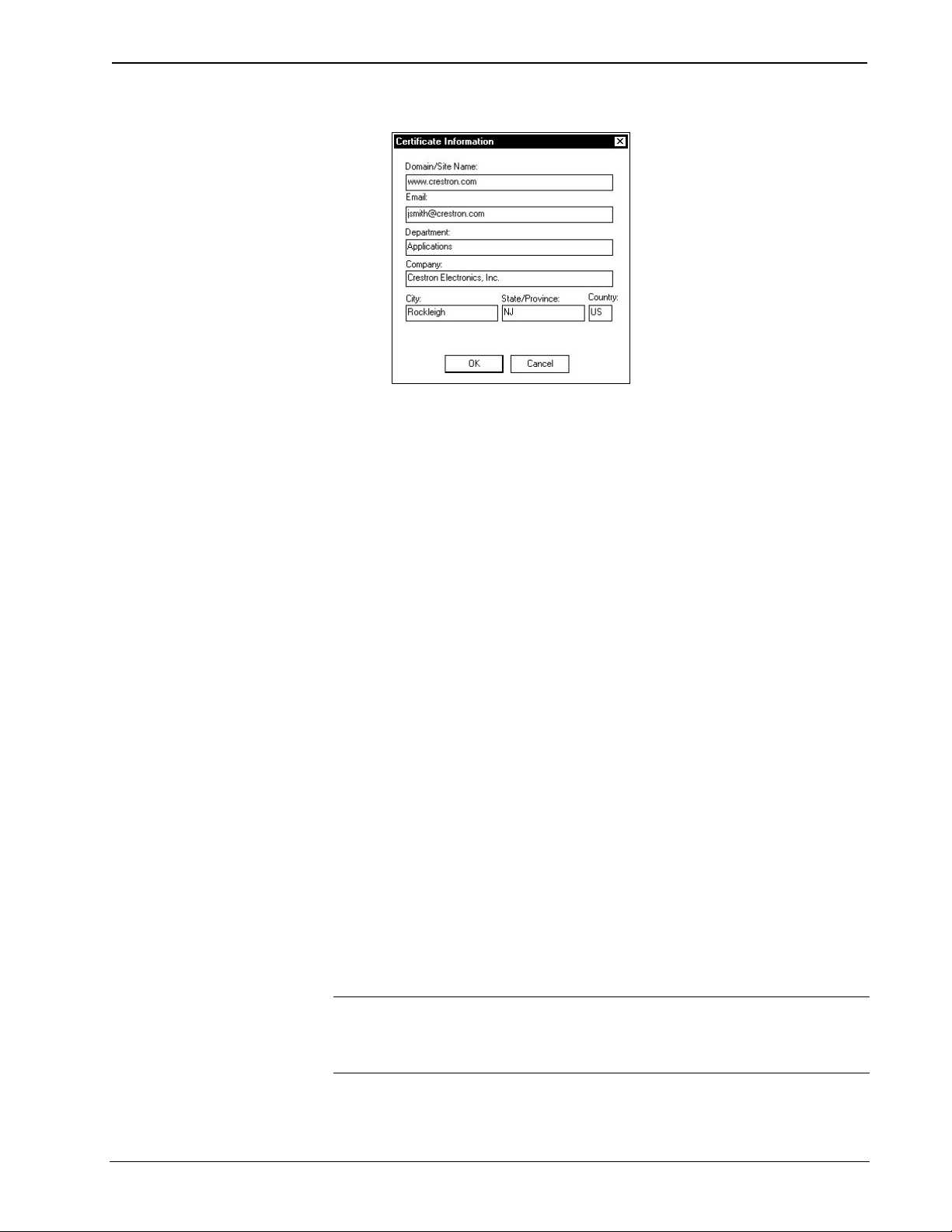
Reference Guide Crestron 2-Series Control System
“Certificate Information” Window
2. Enter the information of the organization requesting the certificate. As
shown in the previous diagram, the information includes the domain name
of the organization, the e-mail address and department of the contact person
making the request, the company name, city and state, and the two-letter
country code.
The domain name is not transferable, and thus must be the one that will
actually be used by clients. The domain name must be officially registered
to the company; otherwise the certificate request will be rejected.
3. Click OK. Viewport will generate the CSR and private key. The files will
be automatically saved in the \SYS directory of the control system. In
addition, Viewport will prompt you to save the CSR file to a directory on
your hard drive: Locate the target directory and click Save.
As described earlier, the CSR file is an ASCII text file that is saved in the
\SYS directory as: \\sys\request.csr. The private key is also saved in the
\SYS directory with a .der extension as: \\sys\srv_key.der. The procedure
for backing up the private key is described in the next section.
The .csr text file is in the following format:
-----BEGIN NEW CERTIFICATE REQUEST----
MIIBZzCCARECAQAwgZQxCzAJBgNVBAYTAlVTMRIwEAYDVQQIEwlob3
N0c3RhdGUxETAPBgNVBAcTCGhvc3RjaXR5MRUwEwYDVQQKEwxob3N0b
mFtZSBpbmMxCjAIBgEAEwNNSVMxGTAXBgNVBAMTEHd3dy5ob3N0bmFt
ZS5jb20xIDAeBgkqhkiG9w0BCQEWEWhvc3RAaG9zdG5hbWUuY29tMFwwDQ
YJKoZIhvcNAQEBBQADSwAwSAJBAMxVTzjNPVWjOHUtMzEsOEWRMIQ
WvilIYliVNtK7jTbyB8WUmucwz3JGfP1LZ5AvT5OQsz8tDsILYItGGliC2tcCAw
EAAaAXMBUGCSqGSIb3DQEJBzEIEwZleHRyYTEwDQYJKoZIhvcNAQEEBQ
ADQQDLIuRV1NBOrlLr3XWI5XiHRHCfQ8gpDOP5MDCdVFgDPvxi5TpQSFV
/3PPUAm6BKAiZxmdpX8BUaEsRdQqNfof3
-----END NEW CERTIFICATE REQUEST-----
NOTE: When sending the CSR to a Certificate Authority it may be necessary to cut
and paste the text between the “Begin new certificate request” and “End new
certificate request” delimiters. To do this you can open the CSR file in a text editor
such as Notepad.
50 • 2-Series Control Systems Reference Guide – DOC. 6256A
Page 55
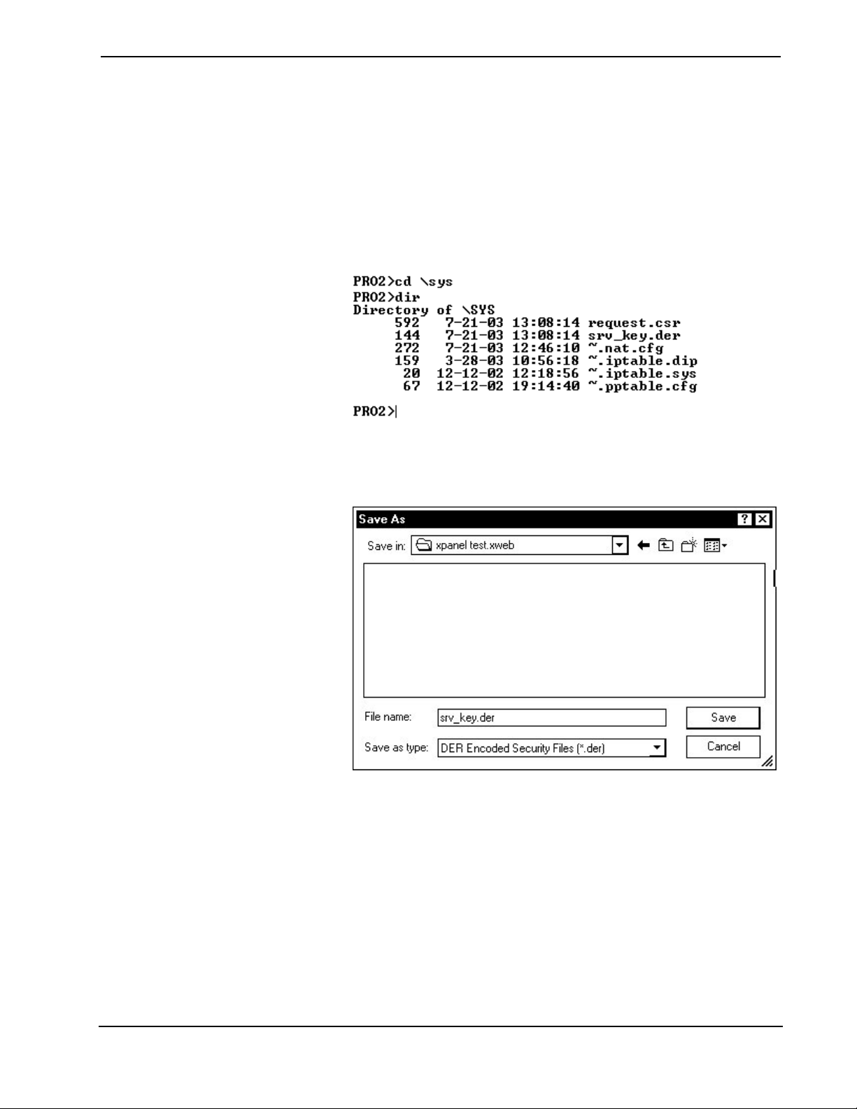
Crestron 2-Series Control Systems Reference Guide
Backup the Private Key
1. Before backing up the private key, the control system’s \SYS directory
should be the active directory so that Viewport can locate the file:
On the Viewport command line, go to the \SYS directory by typing “cd
\sys”. To open the directory type “dir”. This will display a list of files in the
\SYS directory, including the CSR (request.csr) and the private key
(srv_key.der).
“\SYS” Directory (PRO2 Shown)
2. Now that \SYS is the active directory, select File Transfer | Generate
Certificate Request | Backup Key. Viewport will automatically locate the
srv_key.der file.
Save DER File
3. Browse to the location where the .der file is to be stored and click Save.
Since the private key is unique to each CSR, it is a good idea to back up the
file to secure media.
Obtaining the Certificate
As described earlier, the exact procedure for obtaining a certificate differs depending
on the CA, but in all cases you have to submit the CSR along with all verifying
information that the CA requires. Here it may be necessary to open the CSR file in a
text editor such as Notepad and copy and paste the text between the “Begin new
certificate request” and “End new certificate request” delimiters before sending the
file to the CA.
The time it takes to receive the certificate will vary based on how quickly the CA
receives the required documentation.
Reference Guide – DOC. 6256A 2-Series Control Systems • 51
Page 56

Reference Guide Crestron 2-Series Control System
Upload the CA-Signed Certificate
Once the CA validates the CSR, the CA issues the certificate. The certificate is
usually sent to the requester via e-mail, in the following format:
-----BEGIN CERTIFICATE----MIIBZzCCARECAQAwgZQxCzAJBgNVBAYTAlVTMRIwEAYDVQQIEwlob3N0c3RhdG
UxETAPBgNVBAcTCGhvc3RjaXR5MRUwEwYDVQQKEwxob3N0bmFtZSBpbmMxCjAI
BgEAEwNNSVMxGTAXBgNVBAMTEHd3dy5ob3N0bmFtZS5jb20xIDAeBgkqhkiG9w0B
CQEWEWhvc3RAaG9zdG5hbWUuY29tMFwwDQYJKoZIhvcNAQEBBQADSwAwSAJBA
MxVTzjNPVWjOHUtMzEsOEWRMIQWvilIYliVNtK7jTbyB8WUmucwz3JGfP1LZ5AvT5
OQsz8tDsILYItGGliC2tcCAwEAAaAXMBUGCSqGSIb3DQEP/LxbucXaasoh0M1TrU/Rhj
N2wsGVWtKpjnoeXcVZn15OS0adpQtbR4NtmEvL/gXgX+pGkRImUGzYTjVAMjeau48j4
mNW6emf//dWmEHxo2LF2ReHfM3LYM5lh47Wi9Hu/fk87QQTn4lq1aHx0vyCtlMOlRXdc
TptuFywnNTZ1qTctoMbDn+e4M6ILlvyETEnvta0HcMjMOYujNm3SPXOu0shek/Czupy7sr
OvMdjV9hmZaGJ2PBpGAfPUqJh5Gb9VOThRbdomlyA==
-----END CERTIFICATE-----
1. Copy and paste the text between the “Begin Certificate” and “End
Certificate” delimiters to a text file using a text editor such as Notepad.
2. Save the file on your hard drive and name the file srv_cert.cer.
3. In Viewport, select File Transfer | Generate Certificate Request | Upload
Signed Certificate.
4. Locate the directory where you saved srv_cert.cer and click Open. This will
upload the signed certificate to the \SYS directory of the 2-Series control
system in DER format, i.e., \\sys\srv_cert.der.
Upload Root Certificate
Along with the signed certificate, all CAs also electronically give access to what is
called a root certificate. A root certificate is a document that validates the CA itself.
At the time of sending the signed certificate, most CAs provide a URL to where their
root certificate is stored. The buyer of the signed certificate may then download the
root certificate onto the server. Uploading the root certificate is identical to the
procedure for uploading signed certificate. The only difference is that the root
certificate is stored as: \\sys\ rootCA_cert.der.
Enable SSL with CA-signed certificate
1. Open Crestron Toolbox and establish a serial connection to the 2-Series
control system as described in “Serial Connection” on page 5.
2. Select Functions | SSL Management… to open the “SSL Management”
Window.
52 • 2-Series Control Systems Reference Guide – DOC. 6256A
Page 57

Crestron 2-Series Control Systems Reference Guide
“SSL Management” Window
3. Check Enable SSL.
4. Select CA-Signed and click OK. The control system will reboot.
The processor is now SSL protected with a CA-signed certificate. Any Web browser
attempting to communicate with the server will display a locked icon on their screen.
Reference Guide – DOC. 6256A 2-Series Control Systems • 53
Page 58

Reference Guide Crestron 2-Series Control System
Uploading & Using Web Pages
Ethernet-enabled 2-Series control systems provide a built-in Web server for Crestron
e-Control applications. Consult your control system’s Operations Guide for
information on the amount of memory that is allocated for “user files” such as Web
pages, mailbox, and the compiled SPZ program files.
NOTE: The default HTTP/web host port is 80. The web port needs to “talk” to the
Crestron port running with the program (CIP port 41794).
Crestron VisionTools Pro-e
In most cases, a Crestron VisionTools Pro-e browser project is created to generate
the Web pages to be uploaded to the control system.
For Crestron e-Control projects:
When a Crestron e-Control browser project is created, VT Pro-e automatically
creates a folder with the name of the project and a .web extension. This web project
folder contains all the HTML files that are sent to the control system and a Java
subfolder. When creating the project in VT Pro-e, the target type should be set to
BROWSER.
NOTE: The BROWSER project type should only be used to open older existing
projects. For all new projects, e-Control2 (XPANEL) should be used.
For Crestron e-Control2 projects:
When a Crestron e-Control2 project is created, VT Pro-e automatically creates a
folder with the name of the project and a .xweb extension. The web project folder
contains all the necessary Crestron e-Control2 files. In VT Pro-e, the target type
should be set to XPANEL.
An IP ID must be assigned to an e-Control2 project. Additionally, an IP address must
be specified in the project’s properties. For further information on this procedure,
refer to the VT Pro-e online help file.
Crestron Toolbox
To transfer the Web pages to the control system and manage the user password, use
the Fucntions | Web Pages… command to open the “Web Pages” window shown in
the following diagram.
54 • 2-Series Control Systems Reference Guide – DOC. 6256A
Page 59

Crestron 2-Series Control Systems Reference Guide
“Web Pages” Window
From this window, the developer can choose to send an entire project, only files that
have changed, or a single HTML file. Files can be sent to either the control system’s
internal flash memory or a compact flash card (if installed). The developer can also
set and/or change the user password for web pages served by the control system.
To set the control system to act as a web server, select the Enable Web Server check
box and click Apply.
To transfer Web pages:
1. If the Web page project is a VTPro-e project, select the VTPro-e XPanel
Web Project check box and locate the project folder. The default page list
will be grayed out because the default page has already been specified in the
VTPro-e project.
If the Web page project is not a VTPro-e project, clear the check box and
locate the project folder. Then specify the default page. The default page is
the first page to be displayed upon connecting to the Web server.
2. Click the Include Subdirectories check box to transfer the default page
along with all other pages and subfolders that are in the project folder.
Click the Send Modified Files Only check box to transfer only new or
changed files in the project folder.
3. Select the Storage Location: Internal Flash or Compact Flash.
If you select Compact Flash, type the name of the subfolder that will store
the Web project. This subfolder will be under the \HTML directory.
4. Click Send to start the transfer. The Crestron Toolbox will first compact the
file system to free reclaimable space. Then a status bar will display the
progress of the transfer operation.
If the Web server contains files that are not present in the project being sent, those
files will be deleted from the Web server.
To erase the contents of the Web server, click the Erase Web Pages button.
Reference Guide – DOC. 6256A 2-Series Control Systems • 55
Page 60

Reference Guide Crestron 2-Series Control System
To retrieve the current Web project, click the Retrieve button. This allows you to
save the project on the hard drive before transferring a new project to the Web
server.
NOTE: Crestron e-Control 2 projects can use the default “Main.HTML” name or a
user-selectable file name.
To set the user password, refer to “Setting the User Password” on page 56.
SIMPL Windows
For each IP ID in the VT Pro-e browser project, there must be one corresponding
Crestron e-Control PC Interface symbol defined in the SIMPL Windows program.
The PC Interface symbol is one of the Ethernet modules that can be dropped into the
C2ENET-1 or C2ENET-2 card slot.
As with all Ethernet devices, each PC Interface must have an entry in the control
system’s IP table. The IP ID must match the IP ID that was assigned in VT Pro-e,
while the IP address must be set to a loopback: 127.0.0.1, when hosting internal.
Web Page Basics
User pages are served by directing a web browser to the IP address or the URL of the
control system (i.e. http://www.myprocessor.com).
The setup pages are served by directing a web browser to the IP address or the URL
of the control systems administrator interface (i.e.
http://www.myprocessor.com/setup/admin.ssi)
Passwords should be set for the user and administration pages for system security.
Setting the User Password
1. Open Crestron Toolbox and establish communications with the control
system as described on page 5.
2. Select Fucntions | Web Pages to open the “Web Pages” window.
“Web Pages” Window
3. Click Set User Password… to open the “Set Password” window.
56 • 2-Series Control Systems Reference Guide – DOC. 6256A
Page 61

Crestron 2-Series Control Systems Reference Guide
“Set Password” Window
4. Type in a new password and click OK to set the user password.
The password can also be disabled by clicking Disable Password.
Using the User Password
If the user password is set, the login screen shown in the following diagram will be
displayed.
User Login Screen
Enter “user” in the User Name field, the appropriate password, and click OK to
access the user pages.
If a user password has not been set, the login screen will not be displayed and the
browser will display the default user page.
NOTE: CUZ versions 3.112 and later require the name “user” and the correct user
password to browse the user pages. CUZ versions prior to 3.112 provide a lower
level of security than that provided by version 3.112.
Setting the Admin Password
Use Crestron Toolbox to set the admin password for accessing the control system’s
setup pages for Ethernet configuration and Network Address Translator (NAT)
operation. The admin password is the same as the TCP/IP console password.
Reference Guide – DOC. 6256A 2-Series Control Systems • 57
Page 62

Reference Guide Crestron 2-Series Control System
1. Open Crestron Toolbox and establish communications with the control
system as described on page 5.
2. Select Functions | Ethernet Addressing… to open the “Ethernet
Addressing” window.
“Ethernet Addressing” Window
3. Click Set Console Password… to set a new password.
“Set Password” Window
4. Type in a new password and click OK to set the admin password.
The password can also be disabled by clicking Disable Password.
58 • 2-Series Control Systems Reference Guide – DOC. 6256A
Page 63

Crestron 2-Series Control Systems Reference Guide
Using the Admin Password
If the admin password is set, the login screen shown in the following diagram will be
displayed.
Admin Login Screen
Enter the admin name and password and click OK to access the setup pages.
If an admin password has not been set, the login screen will not be displayed and the
browser will display the setup page.
NOTE: CUZ versions 3.112 and later require the name “user” and the correct user
password to browse the user pages. To access the setup pages, the user name
“admin” and the correct admin password must be used. CUZ versions prior to 3.112
provide a lower level of security than that provided by version 3.112.
Reference Guide – DOC. 6256A 2-Series Control Systems • 59
Page 64

Reference Guide Crestron 2-Series Control System
Compiling and Uploading a Program
After a SIMPL Windows program has been completed, the program must be
compiled and uploaded to the control system.
Compiling a Program in SIMPL Windows
To compile the program in SIMPL Windows, simply click the Convert/Compile
button
(you can also press F12). A status bar indicates the progress of the compile
operation. After the operation is complete, a window displays information about the
program such as the number and type of signals, and memory usage.
The compiled program is stored as an SPZ file in the same directory as the source
file.
Uploading a SIMPL Windows Program
The SIMPL Windows file can be uploaded to the control system using SIMPL
Windows or via Crestron Toolbox.
on the SIMPL Windows toolbar, or select Project | Convert/Compile
Upload via SIMPL Windows
1. Start SIMPL Windows.
2. Select File | Open to view the “Open” window, navigate to the SIMPL
Window file (.smw), and click Open.
3. Select Project | Transfer Program.
Upload via Crestron Toolbox
1. Open Crestron Toolbox and establish communications with the control
system as described on page 5.
2. Select Functions | SIMPL Program.
The “SIMPL Program” window contains information about the currently
loaded SIMPL program (if any), and permits you to stop, start, erase,
retrieve, and upload a SIMPL program. This menu also permits you to
upload to compact flash or internal flash.
60 • 2-Series Control Systems Reference Guide – DOC. 6256A
Page 65

Crestron 2-Series Control Systems Reference Guide
“SIMPL Program” Window
3. Click the
“Open” Window
4. Select a file and click Open. When the “SIMPL Program” window re-opens
click Send.
button to browse for a new compiled (.spz) program.
IP Tables
Control systems that run programs using Ethernet communication between the
control system and Ethernet-enabled network devices require an IP table to enable
the control system to identify and communicate with Ethernet equipment on an IP
network. Each controlled Ethernet device has an IP table, also known as a master list.
The master list specifies the IP ID of the controlled device and the IP address or
FQDN of the control system(s) that will send it commands.
The control system’s IP table lists the IP address/fully-qualified domain name and
the IP ID of every device in the network. The IP ID is a hexadecimal value that must
be unique and ranges from 03 to FE.
Reference Guide – DOC. 6256A 2-Series Control Systems • 61
Page 66

Reference Guide Crestron 2-Series Control System
Control System IP Table
IP table information can be entered in one of two ways. The first method creates
what is referred to as a “default” IP table based on information given in the SIMPL
Windows program. The second method uses Crestron Toolbox to manage the IP
table.
NOTE: IP tables used in Ethernet-based Master-Slave applications have their own
IP table requirements. Refer to “Ethernet Master-Slave Modes” on page 36 for
details.
Creating the Default IP Table from SIMPL Windows
While adding Ethernet devices (Ethernet slave processors, Ethernet-enabled
touchpanels, Ethernet devices, or Ethernet modules), the IP information for each
device must be entered in Configuration Manager to determine the information
contained in the default IP table.
1. Double-click the Ethernet device in the SIMPL Windows Configuration
Manager screen to open the “Device Settings” window.
2. Select the IP Net Address tab.
Device Settings Window
3. Click the IP ID button and select the hexadecimal IP ID from the list (The
Remap IP ID at program upload option is reserved for future use.)
62 • 2-Series Control Systems Reference Guide – DOC. 6256A
Page 67

Crestron 2-Series Control Systems Reference Guide
4. Enter the IP address of the device or click Use Host Name to enter the
fully-qualified domain name of the device and click OK.
5. Repeat for every Ethernet-enabled device in the network.
NOTE: If IP information (IP address/hostname) was not entered for all of the
network devices when creating the program, the default IP table will not be created.
The IP table must then be created from Crestron Toolbox. If IP addresses for the
devices are missing, the IP table can be edited from Crestron Toolbox.
6. After completing the SIMPL Windows logic program, compile and upload
the program. To upload the default IP table, click Yes when prompted with
the “Send Default IP Table” window.
Send Default IP Table
The default IP table will be automatically created and uploaded using the IP
information supplied for each network device.
To create a custom IP table with Crestron Toolbox, click No.
Creating and Modifying IP Tables with Crestron
Toolbox
Crestron Toolbox can be used to create and modify a control system’s IP table. Use
Crestron Toolbox to create, modify, or send a control system’s IP table to the control
system without recompiling or transferring a SIMPL Windows program.
1. Open Crestron Toolbox and establish communications with the control
system as described on page 5.
2. Select Funtions | IP Table …. This will open the “IP Table” window.
“IP Table” Window
Reference Guide – DOC. 6256A 2-Series Control Systems • 63
Page 68
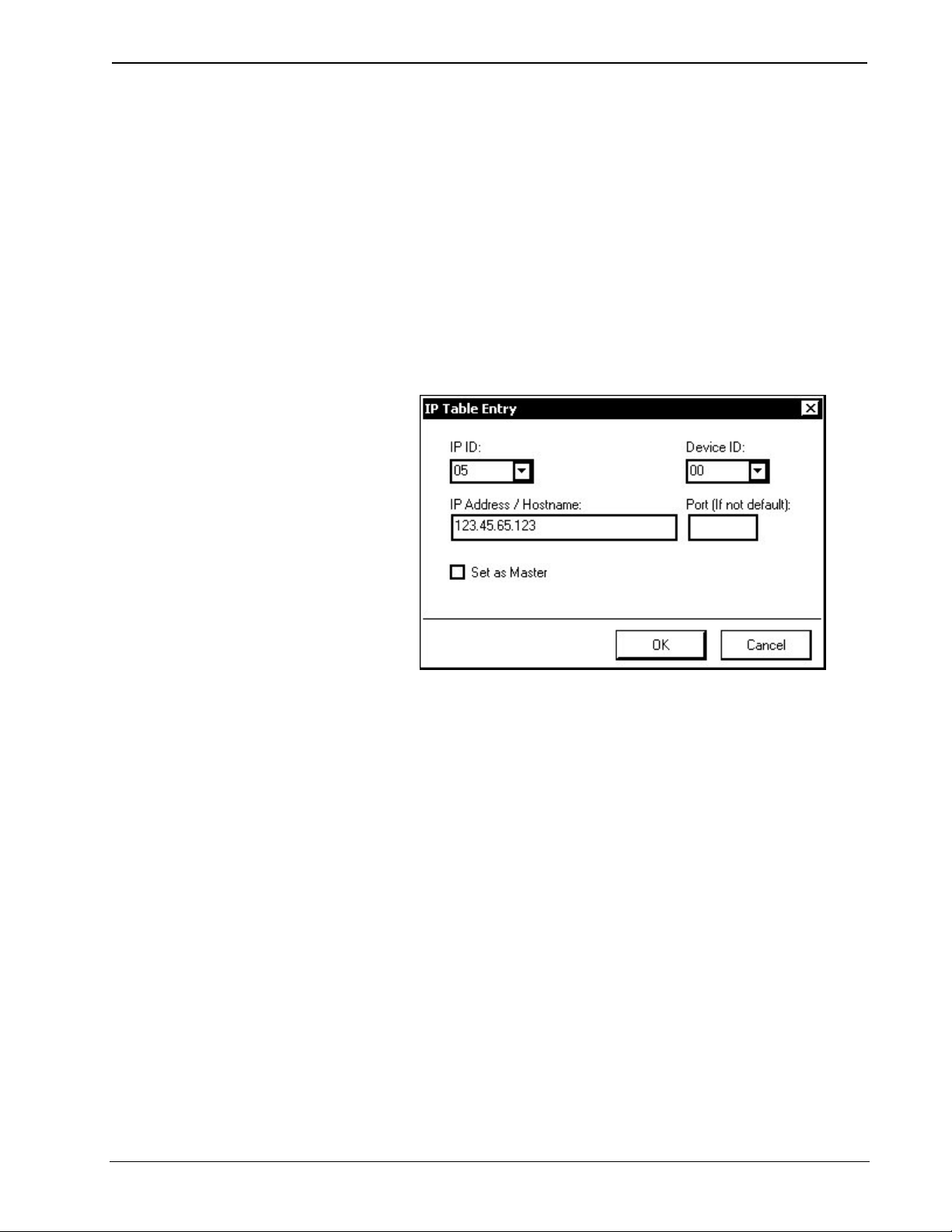
Reference Guide Crestron 2-Series Control System
3. If the control system already has an IP table that is to be modified, click
Load From Device to retrieve the IP table that is stored on the control
system.
4. To add a new table entry, click Add Entry. Existing entries can be
modified by selecting an entry from the list and clicking Modify Entry.
Click Remove (Del) to remove a selected IP entry or click Clear List to
remove all of the entries from the IP table.
To Add an IP table entry:
a) Click Add Entry. The “IP Table Entry” window will open.
b) As shown in the following diagram, select the hexadecimal IP ID of the
device from the IP ID list. The IP ID of the device must match the IP
ID that is specified for the device in the SIMPL Windows program.
“IP Table Entry” Window
c) In the IP Address/Hostname field, enter the static IP address of the
Ethernet device, or if the device is DHCP-enabled, its fully-qualified
domain name.
d) After entering all of the information, click OK to add the device to the
IP table.
e) Repeat this procedure for all the Ethernet devices in the program.
5. Once all of the devices have been listed, click Send to Device* to upload
the IP table to the control system.
Whenever an IP table is sent to the control system, it will overwrite the previously
loaded IP table and reboot the control system.
For Remote Ethernet Processing (Ethernet Slave
Processors):
For information on IP table entries on Ethernet slave processors, refer to “Ethernet
Master-Slave Modes” on page 36.
For Other Ethernet Enabled Devices
The procedure for setting the IP information is different for each Ethernet enabled
device and is described in each device’s manual.
64 • 2-Series Control Systems Reference Guide – DOC. 6256A
Page 69

Crestron 2-Series Control Systems Reference Guide
Uploading Touchpanel Projects
Using the network connection to the control system, compiled VisionTools Pro-e
(VT Pro-e) projects can be relayed through the control system to any Cresnet
touchpanel on the network. VT Pro-e projects can also be directly uploaded via a
touchpanel’s serial port or Ethernet port (if equipped).
The compiled VT Pro-e project file can be uploaded to a touchpanel using VT
Pro-e or Crestron Toolbox. If loading a project to a touchpanel that has an internal
compact flash slot, use Crestron Toolbox.
Upload via VT Pro-e
1. Start VT Pro-e.
2. Select File | Open | Project to view the “Open” window, navigate to the
VT Pro-e file (.vtp), and click Open.
3. Select File | Upload Project. This automatically selects the compiled .vtz
file.
Upload via Crestron Toolbox
1. Open Crestron Toolbox and establish communications with the touchpanel
as described in the touchpanels operations guide.
2. Select Functions | Project.
3. The “Project” window is used to select the project to be uploaded to the
touchpanel.
“Project” Window
Each time a project is selected using the Browse… command, that project is
added to the Project File drop-down list. This makes it convenient to recall
projects without need to browse to a directory.
Selecting Send All Files sends the entire project.
Selecting Send Selected File Types sends only the file types that are
selected. Core Files are files that include touchpanel logic, join number
remapping, and other files related to touchpanel functionality. Graphic Files
are graphics that are displayed on the touchpanel display. Sound Files are
Reference Guide – DOC. 6256A 2-Series Control Systems • 65
Page 70

Reference Guide Crestron 2-Series Control System
WAV files that are assigned within a touchpanel project. Font Files are
fonts that are part of a touchpanel project.
Selecting Send Modified Files Only will only send files that are different
from those that are currently stored in the touchpanel. Note that if any pages
in the touchpanel are not present in the project, those pages will be deleted
from the touchpanel.
4. Click the Browse… button to browse for a new compiled (.vtz) program.
“Open” Window
5. Select a file and click Open. When the “Project” window re-opens click
Send to send the project to the touchpanel.
To verify that the project has been transferred successfully, select Tools |
System Info. The new project information will appear in the upper left
corner of the “System Info” window.
66 • 2-Series Control Systems Reference Guide – DOC. 6256A
Page 71

Crestron 2-Series Control Systems Reference Guide
Firmware Upgrade
To take advantage of all the device features, it is important that the unit contains the
latest firmware available. Please check the Crestron website for the latest version of
firmware. Not every product has a firmware upgrade, but as Crestron improves
functions, adds new features, and extends the capabilities of its products, firmware
upgrades are posted. To upgrade the firmware, complete the following steps.
1. Open Crestron Toolbox and establish communications with the control
system as described on page 5.
2. Select Tools | Network Device Tree to open the Network Device Tree.
3. Right-click on the device whose firmware is to be upgraded and select
Functions | Firmware.
“Network Device Tree” Window – Right-Click Sub Menu
4. The “Firmware” window displays the model and current firmware version.
Click Browse… to find a new firmware file to upload.
Reference Guide – DOC. 6256A 2-Series Control Systems • 67
Page 72

Reference Guide Crestron 2-Series Control System
“Firmware” Window
5. When the following screen appears, browse to locate the firmware (.upg or
.zip) file.
Locate Firmware in the “Open” Window
6. Click Open to select the file.
7. The “Firmware” window reopens indicating the new firmware version to be
uploaded. ZIP files may contain release notes that can be viewed by
clicking View… in the “Firmware” window. Click Send to transfer the new
firmware to the device. Click Close after the firmware has been transferred.
68 • 2-Series Control Systems Reference Guide – DOC. 6256A
Page 73

Crestron 2-Series Control Systems Reference Guide
Updating the Operating System
Introduction
All 2-Series control systems have an operating system file with a .cuz extension.
CUZ update files are used to introduce new features and are occasionally required to
support new devices. CUZ files are enclosed in a zip file that is available for
download from the Crestron website.
To download an update, click the appropriate zip file, choose the Save to Disk
option, and then specify the directory where the update is stored.
NOTE: Crestron software and any files on the website are for Authorized Crestron
dealers and Crestron Authorized Independent Programmers (CAIP) only. New users
may be required to register to obtain access to certain areas of the site (including the
FTP site).
Procedure
To upload the new .cuz to the control system:
1. Open Crestron Toolbox and establish communications with the control
system as described on page 5.
2. Select Functions | Firmware….
3. The “Firmware” window displays the model and current firmware version.
Click Browse… to find a new firmware file to upload.
“Firmware” Window
4. When the following screen appears, browse to locate the firmware (.zip)
file.
Reference Guide – DOC. 6256A 2-Series Control Systems • 69
Page 74

Reference Guide Crestron 2-Series Control System
Locate Firmware in the “Open” Window
5. Click Open to select the file.
6. The “Firmware” window reopens indicating the new firmware version to be
uploaded. ZIP files may contain release notes that can be viewed by
clicking View… in the “Firmware” window. Click Send to transfer the new
firmware to the device. Click Close after the firmware has been transferred.
70 • 2-Series Control Systems Reference Guide – DOC. 6256A
Page 75

Crestron 2-Series Control Systems Reference Guide
Test Manager
The Test Manager is a utility for testing and debugging a SIMPL Windows program,
by monitoring the status of selected signals in real time. Test Manager can test any
program that has been compiled and uploaded to the control system.
Test Manager is launched from within SIMPL Windows by clicking the Test
Manager button or by selecting Tools | Test Manager. Test Manager can also be
opened as a standalone program.
The Test Manager Program
The Test Manager program is broken down into three windows:
• Incoming Data
• Status Window
• Trace Window
Incoming Data
The Incoming Data window displays information received from the control system
and is unrelated to signal monitoring. This is the same data that is shown in the
Incoming Data window of the Crestron Viewport.
Control system data can be saved to disk by selecting Save Incoming Data on the
Edit menu. The data will be saved as an ASCII text file with the extension .tmi.
Text in the Incoming Data window can be copied to the clipboard by selecting Copy
from the Edit menu.
To clear the contents of the Incoming Data window, select Clear Incoming Data
from the Edit menu.
Reference Guide – DOC. 6256A 2-Series Control Systems • 71
Page 76

Reference Guide Crestron 2-Series Control System
Status Window
The Status Window contains a list of signals that are selected for monitoring. The
Status Window displays the following information for each signal:
• The type of signal:
for low digital.
• The signal name.
• Analog signal values, in decimal (default) or percent format. (To specify
percent format, select Show Analogs as Percent from the Options menu.)
• Serial signal values, in ASCII (default) or hexadecimal notation. (To
specify hex, select Show Serials as HEX from the Options menu.)
As digital signals transition in real time, the icon next to the signal will change to
reflect the new state. With analog and serial signals, the new value will overwrite the
previous value.
Signals can be added to the Status Window in a number of ways:
for analog, for serial, for high digital, and
From Test Manager
• Select Add Signal from the Status Window menu. This will display the list
of all signals in the program. Select the signal(s) of interest and click Add.
• Select the signal(s) of interest in the Trace Window and select Add Selected
Signals from Trace Window from the Status Window menu.
• Select the signal(s) of interest in the Trace Window and select Add Signals
to Status Window.
To remove signals from the Status Window, select the signal and click Remove
Signal, or click Remove All Signals to clear the Status Window.
From SIMPL Windows
• In Detail View, right-click the signal and select Set Watch.
• In Program View, right-click the signal and select Set/Clear Watch.
The signal name will appear in bold, indicating that it has been added to the watch
list and will be displayed in the Status Window.
To remove signals from the watch list, right-click the signal and select Clear Watch
if in Detail View, or select Set/Clear Watch if in Program View. This will un-bold
the signal name.
Saving Status Window Data
To save the contents of the Status Window to disk, click Save to Disk from the
Status Window menu. The data will be saved as an ASCII text file with the
extension .tms.
Bookmarks
Test Manager allows signals in the Status Window to be bookmarked. Select Status
Window | Bookmarks | Add and enter a name for the bookmark. To recall the
bookmark point to Bookmarks and click the name of the bookmark.
The Bookmarks submenu can also be used to overwrite a bookmark or remove
existing bookmarks.
72 • 2-Series Control Systems Reference Guide – DOC. 6256A
Page 77

Crestron 2-Series Control Systems Reference Guide
Forcing Signal Transitions
Test Manager provides several commands for changing the states and values of
signals in the Status Window without need to physically press buttons on a device.
These commands are available on the Test Manager toolbar or the Status Window
menu.
Digital Signals
To change the state of a digital signal, select the signal in the Status Window and
click the desired action on the toolbar. Here the commands are only enabled for
"jammable" digital signals, such as button presses or the outputs of buffers.
• Click
• Click
• Click
• Click
(or Assert Signals) to drive the signal high.
(or De-Assert Signals) to drive the signal low.
(or Positive Pulse Signals) to pulse the signal high
(or Negative Pulse Signals) to pulse the signal low.
Analog Signals
To change the value of an analog signal, select the signal in the Status Window and
click the Analog
Window menu. Enter the new value and set the numeric format to Decimal, Percent
or Hex as shown in the following diagram.
“Modify Analog Signal” Window
button, or select Modify Analog Signal from the Status
Serial Signals
To change the value of a serial signal, select the signal in the Status Window and
click the Serial
menu and enter the new value. As shown in the following diagram, Test Manager
supports escape codes for non-printable characters such as carriage return/line feed.
Reference Guide – DOC. 6256A 2-Series Control Systems • 73
button, or select Modify Serial Signal from the Status Window
Page 78
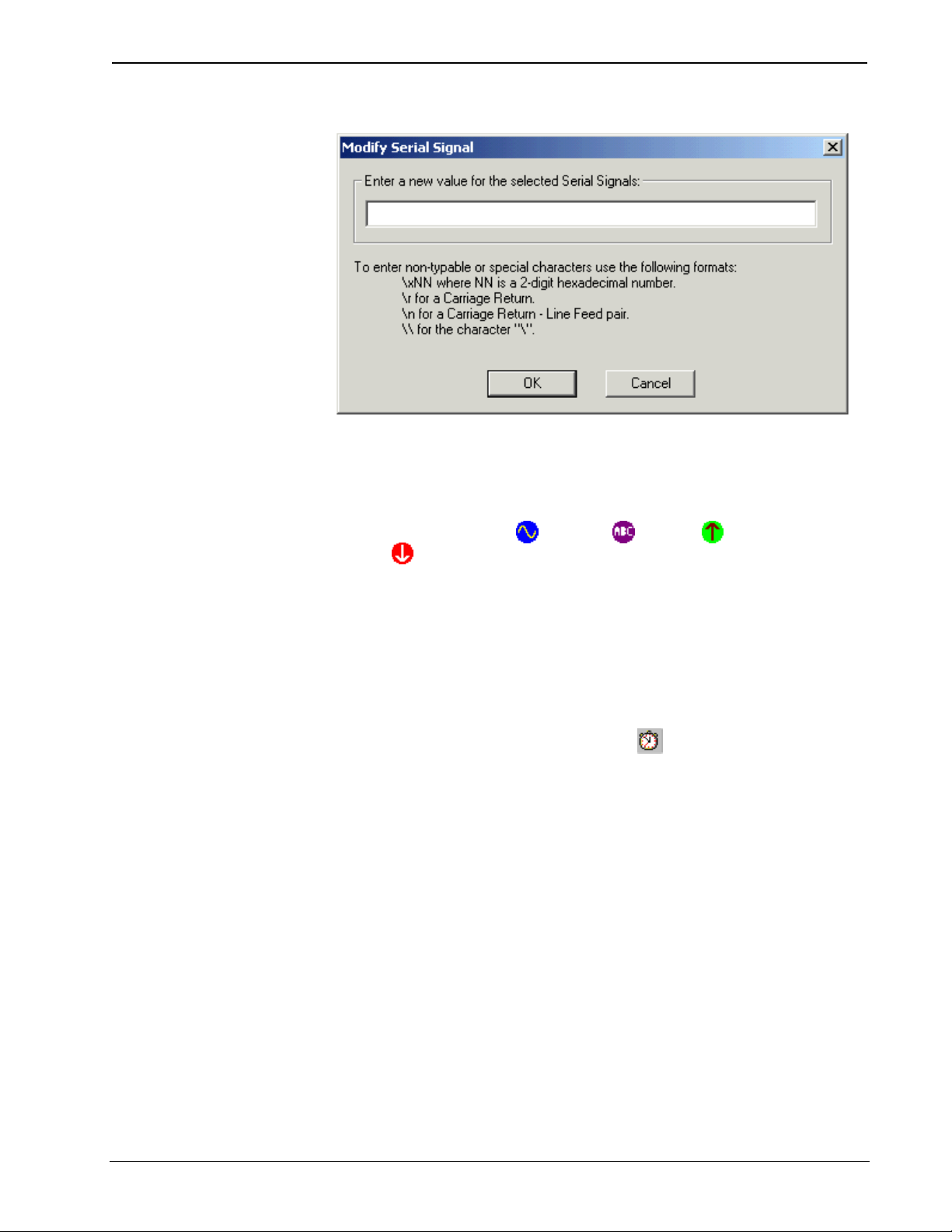
Reference Guide Crestron 2-Series Control System
“Modify Serial Signal” Window
Trace Window
The Trace Window displays the status of the monitored signals. The Trace Window
displays the following information for each signal:
• The type of signal:
for low digital.
• The signal name.
• Analog signal values, in decimal (default) or percent format. (To specify
percent format, select Show Analogs as Percent from the Options menu.)
• Serial signal values, in ASCII (default) or hexadecimal notation. (To
specify hex, select Show Serials as HEX from the Options menu.)
Additionally, the Trace Window includes the date and time (to the nearest second) of
each signal transition. An additional time stamp can be inserted at any point in the
debugging process by clicking the Time Stamp
for analog, for serial, for high digital, and
button.
74 • 2-Series Control Systems Reference Guide – DOC. 6256A
Page 79

Crestron 2-Series Control Systems Reference Guide
Network Analyzer
The Network Analyzer utility helps to identify Cresnet network problems that can be
caused by faulty devices, electrical shorts, or breaks in network wiring. Network
Analyzer takes a sample of the voltage levels on the Cresnet "Y" and "Z" wires for a
specified Net ID.
Network Analyzer is launched from Crestron Toolbox by selecting Tools | Network
Analyzer.
For detailed instructions on using Network Analyzer, refer to the extensive help file
by pressing F1.
Network Analyzer Application
Reference Guide – DOC. 6256A 2-Series Control Systems • 75
Page 80

Reference Guide Crestron 2-Series Control System
Super-Debugger
Super-debugger is a logic analysis tool that shows all data packets coming in and out
of the logic processor. This includes “direct wire access”-type packets from NTX,
DPM, SDPM, IPSDPM, Broadcast from SIMPL and SendToCresnet() from
SIMPL+, as well as startup commands from logic.
The Super-debugger utility will not show packets that are not directed to logic (for
example, CIP keep alive, Cresnet discovery & response, etc.). These packets can be
debugged with the DEBUG command at the console.
Super-debugger can perform the following tasks and can be used for any device that
is being debugged:
• Show transmitted packets.
• Show received packets.
• Show received packets in raw mode.
• Show received packets in interpreted mode.
• Show transmitted packets in raw mode.
• Show transmitted packets in interpreted mode.
These tasks can be used independent of each other.
Packets that are viewed in the raw mode are shown in HEX. Packets that are viewed
in the interpreted mode are shown in printable ASCII. “Broadcast”-type packets may
or may not be shown.
“Direct-to-wire” packets (i.e. from NTX, etc.) are handled in a special way. If the ID
of the direct-to-wire packet is in the program, it will be subject to being picked apart
and interpreted according to the operating mode. If the direct-to-wire packet's ID is
not in the program, it will only be displayed in raw form. The handling of
“unresolvable” packets (those whose ID is not in the program) can be turned on or
off.
The debugger can also turn off console output and log data to compact flash instead.
For a complete list of Super Debugger commands, refer to “Appendix E: SuperDebugger Command Listing” on page 152.
76 • 2-Series Control Systems Reference Guide – DOC. 6256A
Page 81

Crestron 2-Series Control Systems Reference Guide
C2N-NPA8 Network Poll Accelerator
The Network Poll Accelerator (C2N-NPA8) is a device that maintains high data
throughput and low data latency via Cresnet when a large number of Cresnet devices
communicate with a single 2-Series control system. When connected to select
Crestron 2-Series control systems via a high speed serial or Ethernet connection, the
C2N-NPA8 can provide reliable, high-speed communications between the control
system and up to 252 Cresnet devices.
Placing a large number of Cresnet devices on a control system can slow down
polling time as each Cresnet device is polled sequentially by the control system. By
breaking down the Cresnet system into segments, multiple segments can be polled
simultaneously by the control system, hence improving response time.
Similarly, high-traffic devices such as touchpanels, camera controls, and other
devices require more network bandwidth as they transmit and receive larger amounts
of data. By placing these devices on their own segments, other segments can be used
for low-traffic devices such as wall keypads allowing Cresnet traffic to flow more
efficiently.
The C2N-NPA8 is typically recommended for networks with 20 or more devices
(not including button panels). Consult with Crestron's True Blue Support to
determine if a C2N-NPA8 would be beneficial to your system.
The C2N-NPA8 is comprised of 32 Cresnet connectors spread over eight segments
(NET A – NET H). These segments, along with the Cresnet port on the control
system allow the connection of up to 252 Cresnet devices.
For information on configuring a network with a C2N-NPA8, refer to the latest
revision of the C2N-NPA8 Operations Guide (Doc. 6087) which can be downloaded
from the Crestron website.
The C2N-NPA8 is compatible with several 2-Series control systems. However, not
all of the 2-Series products are compatible with the C2N-NPA8. The following table
lists 2-Series control systems (that are currently available as of this writing) that are
compatible with the C2N-NPA8 as well as the communication methods that can be
used.
Processor Compatibility
PROCESSOR SERIAL ETHERNET
AV2 YES1 YES3
C2N-DVP4DI NO YES
CNX-DVP4 NO YES
CP2 YES2 NO
CP2E YES2 YES
MC2E YES2 YES
MC2W YES2 NO
MP2 YES2 NO
MP2E YES2 YES
PAC2 NO YES3
PRO2 YES1 YES3
QM-RMC NO NO
QM-RMCRX(-BA) NO NO
RACK2 NO YES3
Reference Guide – DOC. 6256A 2-Series Control Systems • 77
Page 82

Reference Guide Crestron 2-Series Control System
1. COM ports C through F are poll accelerator-ready
2. COM ports A and B are poll accelerator-ready
3. Requires installation of C2ENET-1 or C2ENET-2 Ethernet card
NOTE: Control systems cannot use a plug in serial card (i.e. a C2COM-3) to
communicate with the C2N-NPA8.
For detailed information on the C2N-NPA8, refer to the latest version of the
C2N-NPA8 Operations Guide (Doc. 6087) which is available for download from the
Crestron website.
78 • 2-Series Control Systems Reference Guide – DOC. 6256A
Page 83

Crestron 2-Series Control Systems Reference Guide
Support Information
Frequently Asked Questions
Following are some frequently asked questions that arise when using a 2-Series
control system:
Frequently Asked Questions
QUESTION ANSWER
My control system is not functioning as
desired. I.e. relays not closing, IR signals
are not emitted, etc. However, I am able to
establish communications with the control
system. How can I determine if the control
system is functioning?
How do I restore my 2-Series control system
to the initial factory default settings?
After uploading a program to my 2-Series
control system, the control system
continually reboots. How do I stabilize the
control system?
The MSG/ERR LED on the front of my 2Series control system is lit. How do I view
and/or clear the message?
When I attempt to upload my program, I get
the error message "Failed to Initialize
NVRAM"? What can I do to fix this?
How do I find the MAC address of my
control system’s Ethernet card?
Use Crestron Toolbox to establish
communications with the control system as
described on page 5. Open a text console
window and type SELFTEST. This command
executes the system self test procedure and
provides feedback that indicates the status of the
control systems outputs.
Use Crestron Toolbox to establish a serial
connection with the control system as described
on page 5. Open a text console window and type
INITIALIZE. This command erases the entire
flash file system (internal or compact flash) and
IP information, Upon completion, type the
command RESTORE. This command restores
the system parameters to the factory default
settings. It will erase any stored program, web
pages and IP information. Type the REBOOT
command to execute a reboot sequence.
Use Crestron Toolbox to establish a serial
connection with the control system as described
on page 5. Open a text console window and type
STOPPROGRAM. This command will prevent
the program from running. The console will
display:
Stopping
Program.................................................................
**Program Stopped**
NOTE: To restart the program, type REBOOT or
press/release the HWR button on the control
system.
Refer to “2-Series Control System Error
Messages” on page 29 for instructions on reading
and clearing messages.
You have configured your system to store run
time data on NVRAM but the NVRAM disk size
was never specified. Refer to “Setting Up an
NVRAM Disk” on page 25 for instructions.
Use Crestron Toolbox to establish a
communications with the control system as
described on page 5. The MAC address
information is contained in the Ethernet section of
the “System Information” window.
(continued on following page)
Reference Guide – DOC. 6256A 2-Series Control Systems • 79
Page 84

Reference Guide Crestron 2-Series Control System
Frequently Asked Questions (continued)
QUESTION ANSWER
My 2-Series control system reboots
unexpectedly. I don’t know if the cause is a
hardware/software anomaly or induced
externally (power failure). I have no error
logs because the reboot sequence cleared
out the error log. What do I do?
Use Crestron Toolbox to establish
communications with the control system as
described on page 5. Open a text console
window and type NVRAMREBOOT ON. This
command will write rebooting messages to
NVRAM. If an anomaly exists, this command will
save the error even though the control system
has rebooted. To view the contents of NVRAM,
open the error log as described on page 30. After
you have captured the error log, turn off the
NVRAMREBOOT command by typing
NVRAMREBOOT OFF.
Watchdog Protection
Crestron 2-Series control systems are equipped with “Watchdog Protection” to
monitor internal registers on the processor as well as software processes.
The hardware watchdog monitors internal registers on a 2-Series control system that
require periodic writing. If the registers are not being written to as required, the
watchdog will send a message to the error log and reboot the control system.
The software watchdog monitors the processor to ensure that no single process in the
system monopolizes the central processing unit. A 2-Series control system requires
certain low-level tasks to run on a regular basis. If the control system is so busy that
one of the low-level tasks is held off for a period of time, the watchdog will send a
message to the error log and reboot the control system.
Capturing Watchdog Messages
When either watchdog triggers a reboot, the processor will display information about
what caused the reboot on the serial port and write the information to the error log.
This information allows engineers at Crestron to track down the cause of the reboot.
If a PC is connected to the control system’s serial port, the information can be
received through a serial connection to the control system console.
When a PC is not connected to a control system’s serial port, the NVRAMREBOOT
function can be used to store error logs containing watchdog messages in NVRAM
before the control system reboots. For information on the NVRAMREBOOT
command, refer to “NVRAMREBOOT” on page 27.
Unexpected reboots are not considered part of normal operation. If your control
system reboots without apparent reason, please capture the watchdog messages in the
error log to NVRAM using the NVRAMREBOOT feature. All messages contained
in the error log should be forwarded to Crestron for further analysis, as workarounds
may be available to prevent future reboots. Your assistance in providing this
information is greatly appreciated.
Further Inquiries
If you cannot locate specific information or have questions after reviewing this
guide, please take advantage of Crestron's award winning customer service team by
calling the Crestron corporate headquarters at 1-888-CRESTRON [1-888-273-7876].
For assistance in your local time zone, refer to the Crestron website
(www.crestron.com
80 • 2-Series Control Systems Reference Guide – DOC. 6256A
) for a listing of Crestron worldwide offices.
Page 85

Crestron 2-Series Control Systems Reference Guide
You can also log onto the online help section of the Crestron website to ask
questions about Crestron products. First-time users will need to establish a user
account to fully benefit from all available features.
Future Updates
As Crestron improves functions, adds new features, and extends the capabilities of
its products, additional information may be made available as manual updates. These
updates are solely electronic and serve as intermediary supplements prior to the
release of a complete technical documentation revision.
Check the Crestron website periodically for manual update availability and its
relevance. Updates are identified as an “Addendum” in the Download column.
Reference Guide – DOC. 6256A 2-Series Control Systems • 81
Page 86

Reference Guide Crestron 2-Series Control System
Appendix A: Interfacing a Control System with a Modem
NOTE: The 2-Series control system must have CUZ version 3.129 or later installed
to ensure proper modem communications. For a general guide to operations, refer to
the “Quick Guide” setup described below. For further details on cabling and other
modem operations, refer to the sections after the “Quick Guide”. The instructions in
this appendix use a modem that can be configured with DIP switches.
NOTE: This procedure requires Crestron Viewport.
Quick Guide
The following are required to interface a PC with a control system via modem:
• Rack Modem: A Hayes compatible (AT command set) modem with DIP
switches that can be set to the required settings. This is the modem that is to
be connected to the control system.
• PC Modem: A Hayes compatible (AT command set) modem that can be
addressed on a COM port, for use with the Viewport utility on the PC.
• Proper equipment to connect the PC modem to the PC (refer to modem
manufacturer's instructions for this).
• Control system-to-modem cable:
⇒ If the control system is a PRO2, AV2, RACK2, PAC2, CP2,
CP2E, MC2, MC2E, or MC2W, use a DB25M-to-DB9M straight
through cable or a DB25F-to-DB25M (or DB9F- to-DB9M) cable
with a null modem adapter
⇒ If the control system is a QM-RMC or a QM-RMCRX(-BA) use a
DB25M-to-DB9M straight-through cable with a DB9F-to-DB9F
gender changer.
• 2-Series control system
Perform the following procedure:
1. Make sure all equipment is powered off.
2. Set the rack modem DIP switches as shown in the following table. Note
that the following table describes the DIP switches of a U.S. Robotics
33.6K Sportster FAX modem. Most Hayes compatible modems should
have similar switching options.
Rack Modem Switch Settings
SWITCH
NUMBER
REQUIRED
SETTING
POSITION DEFINITION
Up DTR normal 1 Down
Down DTR override (always high)
Up Verbal result codes 2 Either
Down Numeric result codes
(continued on following page)
82 • 2-Series Control Systems Reference Guide – DOC. 6256A
Page 87

Crestron 2-Series Control Systems Reference Guide
Rack Modem Switch Settings (continued)
SWITCH
NUMBER
5 Up
REQUIRED
SETTING
POSITION DEFINITION
Up Suppress result codes 3 Up
Down Display result codes
Up Echo offline commands 4 Down
Down No echo of offline commands
Up Auto answer on first ring, or higher if
specified in NVRAM
Down No auto answer
Up Carrier detect normal 6 Either
Down Carrier detect override (always high)
Up Load NVRAM defaults 7 Up
Down Load factory defaults
Up Dumb mode 8 Down
Down Smart mode
3. Connect the rack modem to the power supply provided by the
manufacturer.
For the PRO2, AV2, RACK2, PAC2, CP2, CP2E, MC2, MC2E, MC2W:
4. Plug the null modem adapter into the proper end of the DB25M-to-
DB9M straight-through cable.
5. Plug the DB9M end of the cable into the COMPUTER port on the
control system and continue to step 6.
For the QM-RMC or QM-RMCRX(-BA):
4. Plug the DB9F-to-DB9F gender changer adapter into the DB9M end of
the DB25M-to-DB9M straight-through cable.
5. Plug the other end of the DB9F adapter into the COMPUTER port of
the control system.
6. Plug DB25M end of the cable into the rack modem.
7. Connect the rack modem to an analog telephone line.
8. Turn on the rack modem.
9. Turn on the control system.
10. Verify that the PC modem is connected to an analog telephone line and
functioning per the manufacturer’s instructions.
11. Open the Viewport and select Setup | Communication
Settings…(alternatively, press ALT+D) to configure the connection to
the PC modem. Make sure RTS/CTS is checked, and XON/XOFF is not
checked.
12. To dial the “Rack Modem”, select Remote | Modem | Dial.
13. Enter the phone number of the Rack modem in the, and click OK.
The PC modem will be connected to the Rack modem and can perform any operation
as if the PC were plugged directly into the console.
Reference Guide – DOC. 6256A 2-Series Control Systems • 83
Page 88

Reference Guide Crestron 2-Series Control System
Cable Requirements (2-Series Control System to
Modem)
The cable used to connect a 2-Series processor’s RS-232 computer port to a modem
is a standard DB9 female to DB25 male with a null modem adapter attached. The
null modem adapter can either be DB9F-DB9M or DB25F-DB25M. These parts are
commercially available and do not require custom fabrication.
The pin assignments for the DB9 male-to-DB25 male straight-through cable are
listed in the following table:
Pin Assignments for DB9 Male-to-DB25 Male Straight-Through Cable
DB9 MALE DB25 MALE
PIN NAME PIN NAME
1 CD 8 CD
2 RX 3 RX
3 TX 2 TX
4 DTR 20 DTR
5 Ground 7 Ground
6 DSR 6 DSR
7 RTS 4 RTS
8 CTS 5 CTS
9 RI 22 RI
The pin assignments for the DB9 female-to-DB25 male straight-through cable are
listed in the following table:
Pin Assignments for DB9 Female-to-DB25 Male Straight-Through Cable
DB9 FEMALE DB25 MALE
PIN NAME PIN NAME
1 CD 4 DTR
2 RX 3 TX
3 TX 2 RX
4 DTR 1 CD
4 DTR 6 DSR
5 Ground 5 GND
6 DSR 4 DTR
7 RTS 8 CTS
8 CTS 7 RTS
9 RI - N/A
- N/A 9 RI
84 • 2-Series Control Systems Reference Guide – DOC. 6256A
Page 89

Crestron 2-Series Control Systems Reference Guide
The pin assignments for the DB25 female-to-DB25 male straight-through cable are
listed in the following table:
Pin Assignments for DB25 Female-to-DB25 Male Straight-Through Cable
DB25 FEMALE DB25 MALE
PIN NAME PIN NAME
2 TX 3 RX
3 RX 2 TX
4 RTS 5 CTS
5 CTS 4 RTS
6 DSR 20 DTR
7 GND 7 GND
8 CD 20 DTR
20 DTR 6 DSR
20 DTR 8 CD
22 RI - N/A
- N/A 22 RI
The pin assignments for the DB9 male-to-DB25 male gender changer cable are listed
in the following table:
Pin Assignments for DB9 Male-to-DB25 Male Gender Changer Cable
DB9 MALE DB25 MALE
PIN NAME PIN NAME
1 CD 8 CD
2 RX 3 RX
3 TX 2 TX
4 DTR 20 DTR
5 GND 7 GND
6 DSR 6 DSR
7 RTS 4 RTS
8 CTS 5 CTS
9 RI 22 RI
Cable Requirements (PC to Modem)
The modem on the PC can be either internal or external. There are no special
requirements or cabling required (i.e. it can be either USB or serial). Follow the
guidelines in the modem manufacturer's handbook to determine any cable
requirements.
Modem Configuration (Control System Modem)
In order to support out-of-the box communications with a modem, the modem must
have DIP switches to activate and/or deactivate certain functions. The DIP switch
settings are described in “Quick Guide” on page 82. Any compatible modem can be
used as long as it has the same settings.
Crestron does support modems without DIP switches (software-configurable).
However, the modem may support commands that mimic the DIP switch settings
described in “Quick Guide” on page 82. This type of modem must first be configured
first plugging it into a PC, and as such, is not “out of the box” compatible.
The control system must have operating system version 3.129 or later to support outof-the-box modem communications. When the control system is rebooted (i.e.
powered up, HW-R pressed and released, REBOOT command issued at console),
Reference Guide – DOC. 6256A 2-Series Control Systems • 85
Page 90

Reference Guide Crestron 2-Series Control System
the control system will output the AT command, followed by a carriage
return/linefeed (\x0D\x0A). It will then wait three seconds, and then continue with
the normal bootup sequence. The AT command will only be seen on the serial
console. It will not be seen on any other system console.
Once the modem is connected to the control system and powered on, it is necessary
to reboot the control system (i.e. cycling power, HW-R pressed and released, or
REBOOT command issued at console) in order for the AT command to be sent out.
When the control system sends the AT command to the modem, the modem will
synchronize its serial port baud rate to the serial port baud rate of the COMPUTER
port of the 2-Series control system.
Modem Communications Speed
The final connection speed modem connection is only as fast as the slowest link.
There are three links in a modem connection:
• PC to modem.
• Modem to modem.
• Modem to 2-Series control system.
PC to Modem
The PC modem is required to support communications through a COM port.
Although it has not been tested by Crestron, a USB modem that provides Microsoft
Windows
should also work. A COM interface is required, since communications to the control
system for uploading programs, etc. is done through the viewport, which only works
through a COM port.
It is recommended to set the Viewport (press ALT+D) to 115200 baud, no parity, 8
data bits, 1 stop bit, and RTS/CTS: ON for communications.
®
driver-level support for treating the modem as if it were on a COM port
Modem to Modem
The speed between modems can vary greatly depending on the quality of the phone
lines and other factors that are dependent on the telephone system.
Modem to Control System
It is recommended to leave the serial port baud rate of the 2-Series control system at
115200 baud, no parity, 8 data 1its, 1 stop bit, and RTS/CTS: ON to achieve
maximum throughput.
Handshaking is enabled on both serial connections (PC to modem and modem to
2-Series control system). Therefore, no matter how fast the link, proper hardware
handshaking ensures that there will be no overrun conditions.
Notes for QM-RMC and QM-RMCRX(-BA)
The QM-RMC and QM-RMCRX(-BA) do not have dedicated console ports. The
COM B port is used as both a console port and a program addressable COM port.
When either system is first powered up out of the box, COM B will operate in the
console mode. If there is no program loaded on to the system, COM B will operate
in the console mode. When a program is loaded and the control system reboots (i.e.
86 • 2-Series Control Systems Reference Guide – DOC. 6256A
Page 91

Crestron 2-Series Control Systems Reference Guide
by pressing HW-R or cycling power, NOT typing “reboot” at the console in this
case.), COM B will act as a program addressable COM port.
To keep the COM B operating in the console mode permanently, use the
COMCONSOLEMODE ON command in Viewport. For further details, refer to
“2-Series Console Commands for Modem Configuration” below.
2-Series Console Commands for Modem
Configuration
The modem initialization command can be changed with the console command
MODEMINITSTRING. However, the initialization generally is not changed unless
a modem is being used.
MODEMINITSTRING Console Commands
PRO2> MODEMINITSTRING
Current Init String: AT[0D][0A]
PRO2> MODEMINITSTRING ?
MODEMINITSTRING "{init string}"
{init string}: String to send to modem. 64
characters Max.
No Arguments: Shows current init string
By default, the modem initialization string (and subsequent three second delay) is
sent at bootup. To turn this off and prevent the three second delay, use the
SENDMODEMINITSTRING command. This feature can be used when a modem
is not being used and the developer wants to shorten the control system’s startup
time.
SENDMODEMINITSTRING Console Commands
PRO2> SENDMODEMINITSTRING ?
SENDMODEMINITSTRING {ON|OFF}
ON: Sends the modem init string at startup.
OFF: Does not send the modem init string at
startup.
No Arguments: Show current setting.
PRO2>SENDMODEMINITSTRING OFF
New Setting: OFF
Reference Guide – DOC. 6256A 2-Series Control Systems • 87
Page 92

Reference Guide Crestron 2-Series Control System
To change the default state of the QM-RMC or QM-RMCRX's shared console port,
the COMCONSOLEMODE command can be used:
COMCONSOLEMODE Console Commands
QM-RMC> COMCONSOLEMODE ?
COMCONSOLEMODE {ON|OFF}
ON: Lock COM B to console mode.
OFF: Restore default COM B behavior.
No Arguments: Show current state.
QM-RMC>COMCONSOLEMODE
COMCONSOLEMODE: Current state is OFF.
QM-RMC>COMCONSOLEMODE ON
New COMCONSOLEMODE saved. Reboot to take
effect.
88 • 2-Series Control Systems Reference Guide – DOC. 6256A
Page 93

Crestron 2-Series Control Systems Reference Guide
Appendix B: Passthrough Mode
NOTE: This procedure requires the use of the Crestron Viewport.
Passthrough Mode allows a control system to act as a conduit to a device that is
serially connected to the Crestron system. Viewport can then serially communicate
with a controlled device separate from the control system program. This aids in
troubleshooting a serial device that is connected to the network by isolating the
device from the system or the program running in the control system without moving
any wiring.
NOTE: Before using the Passthrough Mode to connect to a serial port on an
Ethernet device, the IP ID and associated IP address of the Ethernet device must
be listed in the control system's IP table.
The Passthrough Mode cannot be used with Cresnet devices that utilize slots in the
SIMPL Windows programming symbol. For example the COM port on the
C2N-CAMIDSPT is designated as Slot 2, Port A. The Passthrough Mode cannot be
used to access this COM port. The COM ports on the ST-COM are not within slots
and can use Passthrough for these COM ports.
The System Views of SIMPL Windows shows the programmer if a COM port is a
port on a device or a port within a slot on a device. The following diagram shows the
System Views for a system with a ST-COM RS-232/422 COM Module and a
C2N-CAMIDSPT Digital Servo Pan/Tilt Head.
System View of ST-COM and C2N-CAMIDSPT
To enter the Passthrough Mode for connecting to serial devices:
1. After using Viewport to establish communication with the processor, select
Functions | Enter Passthrough Mode (CNX / 2-Series only).
NOTE: For instructions on establishing communications with the control
system, refer to the Viewport help file.
Reference Guide – DOC. 6256A 2-Series Control Systems • 89
Page 94

Reference Guide Crestron 2-Series Control System
“Passthrough Mode” Window
2. Select the type of connection the serial-equipped device has to the control
system: Slot (card slot on a control system), Cresnet, or Ethernet).
3. Select the card slot number (1 through 16 on a control system), Cresnet ID
(for Cresnet devices), or IP ID (for Ethernet devices).
4. Specify the port (Port A through Port F) where the serial device is
connected.
5. Specify the serial protocol that the device expects. The parameters include
the baud rate, parity, the number of data bits and stop bits, the protocol
(RS-232, RS-422 or RS-485), and the settings for software or hardware
handshaking. This information is provided by the unit's documentation.
6. Verify communications with the serial peripheral by sending commands
using the device’s serial protocol.
7. Exit the Passthrough Mode by selecting Functions | Exit Passthrough
Mode (2-Series Only).
90 • 2-Series Control Systems Reference Guide – DOC. 6256A
Page 95

Crestron 2-Series Control Systems Reference Guide
Appendix C: Console Command Listing
Details about each of the acceptable commands that can be interpreted by the
2-Series dual bus control system are described in the following tables. Commands
are listed alphabetically. Each listing includes a description of the command, a list of
help menus
definitions of parameters that may be included in the syntax, a list of possible
sources
recognized by the processor, and the specific processor group
command. For a description of each detail listed for a given command, refer to the
SAMPLE COMMAND on page 22.
NOTE: The entire command name (i.e., ADDMaster) may not need to be entered
for recognition. The capitalized letters of the command name listed in the syntax
(i.e., ADDM) are all that is required to interpret the command. However, as more
commands are added to the list over time, it may be necessary to expand the
recognizable abbreviation required for a command. Therefore, to avoid confusion in
the future, it is highly recommended to use the full command name if automating
commands or implementing the SIMPL Windows Console logic symbol.
1
that contain the command, the proper syntax for entering the command,
2
for the command, the minimum CUZ with which the command is
1. Help menus are defined in more detail with “Command Groups” on page 18.
2. Possible sources refers to the methods by which console commands are delivered to the control
system, as explained on page 16.
3. Processor groups are defined in more detail with “Processor Groups” on page 21.
3
that supports the
NOTE: Not all parameters listed in the syntax are necessary. Parameters that are
contained within brackets "[…]" are optional. Furthermore (for the sake of the
commands shown in this appendix), parameters in lower case represent a placeholder
for some value or variable. Upper case parameters separated by a vertical mark "|"
(i.e., ON | OFF) are mutually exclusive of each other. Enter only one of the available
upper case parameters verbatim (interpretation is case insensitive). If the parameter
is listed in lower and upper case, only the upper case portion of the parameter is
necessary for interpretation.
2-Series Console Commands
ADDDNS
Description: This command adds a Domain Name Service (DNS) server to the processor's search list. The processor
Help Menu(s): Ethernet
Syntax: ADDDns ip_address
Parameters: ip_address - the Internet Protocol (IP) address of the DNS server in dot decimal format (eg.
Possible Source: RS-232, CTP, Telnet, User Program
Minimum CUZ: 2.006
Processor Group: Ethernet Processors
(continued on next page)
can hold a list of two DNS servers in order to resolve name references to IP address.
255.255.255.255)
Reference Guide – DOC. 6256A 2-Series Control Systems • 91
Page 96

Reference Guide Crestron 2-Series Control System
2-Series Console Commands (continued)
ADDMASTER
Description: This command adds a master CIP node to the system's IP table. By adding a master to the IP table, the
Help Menu(s): Ethernet, Main
Syntax: ADDMaster cip_id ip_address [device_id]
Parameters: cip_id - the IP ID of the node in hexadecimal notation
ip_address/name - the Internet Protocol (IP) address of the remote node in dot decimal format (eg.
device_id - optional ID used in join number remapping (not needed for most 2-Series systems)
Possible Source: RS-232, CTP, Telnet, User Program
Minimum CUZ: 1.001 (for peer-to-peer), 3.044 (for Master entry capability)
Processor Group: Ethernet Processors
ADDPORTMAP
Description: This command adds a portmap to the Network Address Translator (NAT) table. The external port
Help Menu(s): Ethernet
Syntax: ADDPortmap ext_port int_port ip_address protocol
Parameters: ext_port - port number on the WAN side of NAT
int_port - port number on the LAN side of NAT
ip_address - IP address (in dot decimal notation) of the device on the LAN side of NAT
protocol - IP protocol for the portmap service (TCP | UDP | Both)
Possible Source: RS-232, CTP, Telnet, User Program
Minimum CUZ: 2.004
Processor Group: Dual Ethernet Processors
ADDSLAVE
Description: This command adds a peer/slave CIP node to the system's IP table. This command was added to
Help Menu(s): Ethernet, Main
Syntax: ADDSlave cip_id ip_address [device_id]
Parameters: cip_id - the ID of the node in hexadecimal notation
ip_address/name - the Internet Protocol (IP) address of the remote node in dot decimal format (eg.
device_id - optional ID used in join number remapping (not needed for most 2-Series systems). Refer to
Possible Source: RS-232, CTP, Telnet, User Program
Minimum CUZ: 3.015 (for Master entry capability)
Processor Group: Ethernet Processors
processor becomes an Ethernet slave to the node specified in the master entry. A CIP node is
completely specified by its CIP ID number and the IP addresses/site name of each end. The new IP
table is stored in permanent memory for retrieval. The system should be rebooted to recognize the new
node. There can only be one master.
255.255.255.255) or a site name to be resolved by DNS
number, internal port number, IP address, and protocol define a portmap. Requires the C2ENET-2.
differentiate for the ADDMASTER command when slave mode was fully supported. A CIP node is
completely specified by its CIP ID number and the IP addresses/site name of each end. The new IP
table is stored in permanent memory for retrieval. The system should be rebooted to recognize the new
node.
255.255.255.255) or a site name to be resolved by DNS
“Appendix F: Join Number Remapping (JNR)” on page 154.
(continued on next page)
92 • 2-Series Control Systems Reference Guide – DOC. 6256A
Page 97

Crestron 2-Series Control Systems Reference Guide
2-Series Console Commands (continued)
AUTONEGOT
Description: This command sets the state of the autonegotiation process on the Ethernet device(s). Autonegotiation
Help Menu(s): Ethernet
Syntax: AUTONEGOT [device_num (ON | 10HALF | 10FULL | 100HALF | 100FULL)]
Parameters: device_num - number of the Ethernet device to set (0 or 1)
ON - autonegotiation is on (default)
10HALF - autonegotiation is OFF, use 10mps, half duplex
10FULL - autonegotiation is OFF, use 10mps, full duplex
100HALF - autonegotiation is OFF, use 100mps, half duplex
100FULL - autonegotiation is OFF, use 100mps, full duplex
Possible Source: RS-232, CTP, Telnet, User Program
Minimum CUZ: 1.001
Processor Group: Ethernet Processors
BROADCAST
Description: This command enables/disables the broadcasting of error messages. The messages will be logged
Help Menu(s): System
Syntax: BROADcast [ON | OFF]
Parameters: ON - turns on broadcasting of error messages (default)
OFF - turns off broadcasting of error messages
Possible Source: RS-232, CTP, Telnet, User Program
Minimum CUZ: 1.001
Processor Group: All Processors
BYE
Description: This command cancels a connection over the Ethernet, whether to the Telnet or CTP ports. If password
Help Menu(s): System
Syntax: BYE
Parameters: none
Possible Source: CTP, Telnet
Minimum CUZ: 1.001
Processor Group: Ethernet Processors
CALTOUCH
Description: This command puts the CNX-DVP4/C2N-DVP4DI into touch screen calibration mode.
Help Menu(s): Device
Syntax: CALTOUCH
Parameters: none
Possible Source: RS-232, CTP, Telnet, User Program
Minimum CUZ: 1.017
Processor Group: Display Processors
is the process of automatically determining the speed of the Ethernet network. Entering the command
without a parameter displays the current setting.
whether or not they are broadcast. Entering the command without a parameter displays the current state.
protection is enabled, the password has to be re-entered before connection is re-established.
(continued on next page)
Reference Guide – DOC. 6256A 2-Series Control Systems • 93
Page 98

Reference Guide Crestron 2-Series Control System
2-Series Console Commands (continued)
CARDS
Description: This command displays the cards in the system.
Help Menu(s): Main, System
Syntax: CARDS
Parameters: none
Possible Source: RS-232, CTP, Telnet, User Program
Minimum CUZ: 1.001
Processor Group: All Processors
CD
Description: This command changes the current working file directory. Refer to "File System" in this Reference Guide
Help Menu(s): File
Syntax: CD [directory]
Parameters: directory – ASCII string representing the desired directory
Possible Source: RS-232, CTP, Telnet, User Program
Minimum CUZ: 1.001
Processor Group: All Processors
CFAUTORUN
Description: This command enables/disables the autorun feature of compact flash. If enabled, the program residing
Help Menu(s): File
Syntax: CFAUTOrun [ON | OFF]
Parameters: ON - turns on compact flash autorun
OFF - turns off compact flash autorun (default)
Possible Source: RS-232, CTP, Telnet, User Program
Minimum CUZ: 2.004
Processor Group: Compact Flash Processors
CFLOGERR
Description: This command enables/disables logging errors to compact flash. The errors are written to a file in the
Help Menu(s): File
Syntax: CFLOGerr [ON | OFF]
Parameters: ON - turns on compact flash error logging
OFF - turns off compact flash error logging (default)
Possible Source: RS-232, CTP, Telnet, User Program
Minimum CUZ: 2.004
Processor Group: Compact Flash Processors
for details. The parameter to this command can be relative or absolute. Entering the command without a
parameter displays the current setting.
on the compact flash is immediately started when the compact flash card is inserted into the system.
Also, any web pages that reside on the compact flash are immediately active. If autorun is enabled when
the compact flash is extracted and the system is currently running a programfrom the compact flash, the
processor stops the currently running program and restarts with the program stored on internal flash.
Entering the command without a parameter displays the current setting.
root of compact flash named ErrorLog.Txt. This command can be used to protect the error log from a
processor report (which would clear the normal error log). Entering the command without a parameter
displays the current setting.
(continued on next page)
94 • 2-Series Control Systems Reference Guide – DOC. 6256A
Page 99

Crestron 2-Series Control Systems Reference Guide
2-Series Console Commands (continued)
CFPROJDIRS
Description: This command displays the project directories on the compact flash. A "project directory" is a directory that
Help Menu(s): File
Syntax: CFPROJdirs
Parameters: none
Possible Source: RS-232, CTP, Telnet, User Program
Minimum CUZ: 2.004
Processor Group: Compact Flash Processors
CFTRANSFER
Description: This command transfers project to/from compact flash from/to internal flash. There is only one destination in
Help Menu(s): File
Syntax: CFTRANSfer FROM|TO path
Parameters: FROM|TO - indicates whether transfering from/to compact flash
path - path for the project on compact flash (Refer to "File System" in this Reference Guide for details.)
Possible Source: RS-232, CTP, Telnet, User Program
Minimum CUZ: 2.004
Processor Group: Compact Flash Processors
CIPPORT
Description: This command specifies the port number to be used for the CIP interface. It should only be used in the few
Help Menu(s): Ethernet
Syntax: CIPPORT [portnumber]
Parameters: portnumber - port number for CIP activity (default: 41794)
Possible Source: RS-232, CTP, Telnet, User Program
Minimum CUZ: 1.001
Processor Group: Ethernet Processors
CLEARERR
Description: This command clears the error log. The last 100 entries to the log are kept by the system.
Help Menu(s): System
Syntax: CLEARERR
Parameters: none
Possible Source: RS-232, CTP, Telnet, User Program
Minimum CUZ: 1.001
Processor Group: All Processors
contains SIMPL and SPLUS subdirectories. This command should be used in tandem with CFTRANSFER.
internal flash for the project, but there can be multiple destinations on the compact flash. The CFPROJDIRS
command can help specify the valid locations. This command will not create a project directory if it does not
exist.
cases where there is a conflict and used with extreme caution. Entering the command without a parameter
displays the current setting.
(continued on next page)
Reference Guide – DOC. 6256A 2-Series Control Systems • 95
Page 100

Reference Guide Crestron 2-Series Control System
2-Series Console Commands (continued)
CNETID
Description: This command changes the Cresnet ID for the processor. Changing the ID to anything other than 2 configures
Help Menu(s): System
Syntax: CNETid [id]
Parameters: id - the ID of the system in hexadecimal notation (default: 2)
Possible Source: RS-232, CTP, Telnet, User Program
Minimum CUZ: 1.017 (CNX-DVP4, 3.044 (all others)
Processor Group: Cresnet Processors
COMCONSOLEMODE
Description: This command changes the default state of the QM-RMC or QM-RMCRX(-BA)’s shared console port. The
Help Menu(s): System
Syntax: COMCONSOLEMODE
Parameters: ON – Locks COM B to console mode
OFF – Restore default COM B behavior
Possible Source: RS-232, CTP, Telnet, User Program
Minimum CUZ: 3.129
Processor Group: QuickMedia Processors
COMPACT
Description: This command reclaims internal flash file space by removing invalid (deleted) files from the system. The file
Help Menu(s): File
Syntax: COMPACT
Parameters: none
Possible Source: RS-232, CTP, Telnet, User Program
Minimum CUZ: 1.001
Processor Group: All Processors
CTPPORT
Description: This command specifies the port number to be used for the CTP (Crestron Terminal Protocol) console
Help Menu(s): Ethernet
Syntax: CTPPORT [portnumber]
Parameters: portnumber – port number for console connection (default: 41795)
Possible Source: RS-232, CTP, Telnet, User Program
Minimum CUZ: 1.001
Processor Group: Ethernet Processors
the processor as a Cresnet slave. Entering the command without a parameter displays the current setting.
shared console port can operate as a console port for PC-to-Console communications or as a serial port.
Entering the command without a parameter displays the current setting.
system is compacted to remove the holes left by the invalid files. The rest of the flash file space is cleared to
accept new files. The FREE command can be used to display the amount of file space that would be
reclaimed by the COMPACT command. Normally, the user need not initiate the COMPACT command. The
Crestron Viewport manages its usage.
interface. It should only be used in the few cases where there is a conflict and used with extreme caution.
Entering the command without a parameter displays the current setting.
(continued on next page)
96 • 2-Series Control Systems Reference Guide – DOC. 6256A
 Loading...