

Page 1
MC4/MC4-I
The Crestron® MC4 and MC4-I 4-Series media room controllers provide
secure, high-performance, cost-effective control processors and
interfaces. Their small form factor and versatile mounting options make
them ideal for applications such as single-room systems, small to
medium-sized homes and offices, and MDUs (multidwelling units). The
controlsystem includes a built-in infiNET EX® and ER wireless gateway
for acquiring wireless devices as well as numerous control ports for
controlling wired devices.
Quick Start
Install the Device
The control system may be mounted into a rack or onto a flat surface.
Rack Mounting
NOTE:TheMC4 and MC4-I are functionally similar. For simplicity
within this guide, the term "control system"is used to refer to both
the MC4 and MC4-Iunless otherwise noted.
In the Box
1 MC4 or MC4-I, 4-Series Media Room Controller
Additional Items
1 Rack Ear, Left (2053897)
1 Rack Ear, Right (2053896)
4 Nut, 10-32 (2004889)
1 Antenna, Dual Band, 2.4/5.8 GHz (2052945)
1 Cable, CAT5e, 5 ft (1.52 m) (2022311)
2 Connector, 3-Pin (2003575)
4 Connector, 4-Pin (2003576)
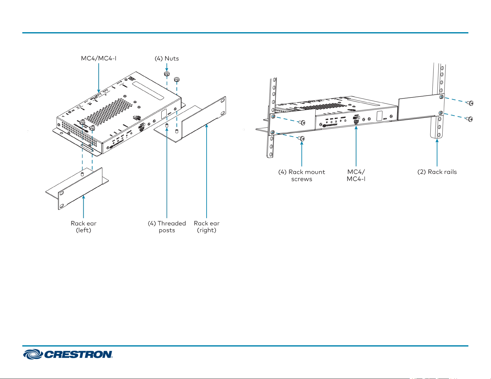
The control system occupies 1U of rack space when using the provided
rack ears.
1. Attach the rack ears to the device:
a. Insert the two threaded posts on the left rack ear up and into the
front opening in the left mounting flange of the control system.
Repeat this step for the right rack ear.
b. Attach the four provided nuts to the threaded posts to secure the
rack ears to the control system.
1
Page 2
MC4/MC4-I
Refer to the following image for rack ear placement. 2. Secure the control system to the rack rails using four rack mounting
screws (not provided).
Quick Start
Surface Mounting
Use four mounting screws(not provided)to mount the control system to
a flat surface such as a wall or under a table. The control system can also
be mounted behind a flat panel display or similar equipment.
2
Page 3
MC4/MC4-I
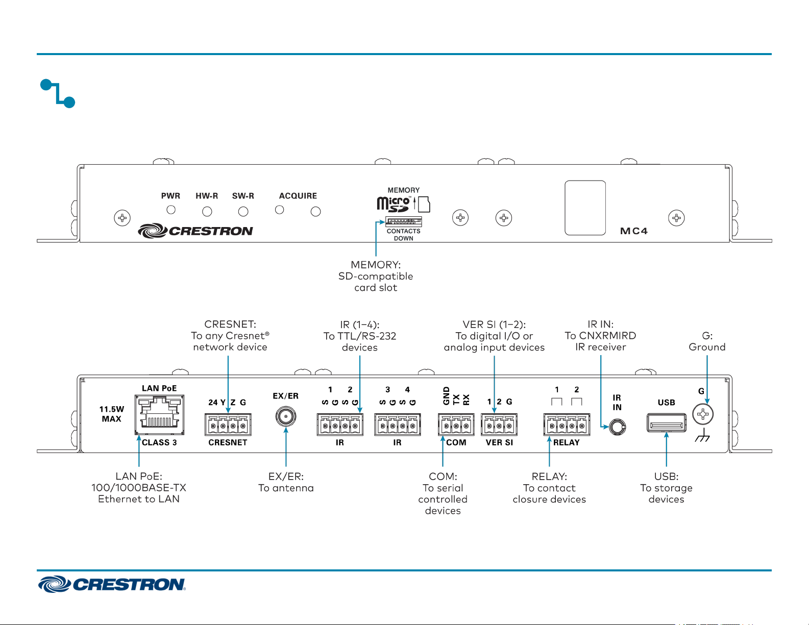
Connect the Device
Make all necessary connections to the control system as shown below.
Front Panel Connections
Rear Panel Connections
Quick Start
3
Page 4

MC4/MC4-I
Observe the following when connecting the control system:
l The control system is powered over PoE (Power over Ethernet)via a
Crestron PoEinjector (PWE-4803RU) or a Crestron PoEswitch
(CEN-SW-POE-5 or CEN-SWPOE-16). All PoEequipment is sold
separately.
l The included cables may not be extended.
l Mount the included antenna per the guidelines described in Mount the
Antenna.
l Connect the chassis ground lug to a known earth ground circuit (such
as building steel) to ensure that the control system is grounded
properly.
l Apply power after all connections have been made.
Mount the Antenna
The included antenna should be placed in a location that maximizes signal
strength and limits impedance. Refer to the Best Practices for Installation
and Setup of Crestron RFProducts (Doc. 6689) at
www.crestron.com/manuals.
Quick Start
Configure the Device
The control system may be configured using the provided web
configuration interface. The interface can be accessed using the control
system IP address or the Crestron XiOCloud™ service.
Configuration via IP Address
To access the web configuration interface using the control system
IPaddress:
NOTE:The control system ships with DHCPenabled. A DHCPserver is
required to access the web configuration interface via the device
IPaddress.
1. Connect the control system to the network.
2. Use the Device Discovery tool in Crestron Toolbox™ software to
discover the control system and its IP address on the network.
3. Enter the control system IPaddress into a web browser.
If installing the control system in a rack enclosure, the antenna should be
mounted outside of the enclosure using the Crestron ANT-EXT-10 (sold
separately). For more information, refer to the ANT-EXT-10 Installation
Guide (Doc. 7047) at www.crestron.com/manuals.
4
Page 5

MC4/MC4-I
Configuration via Crestron XiOCloud
The Crestron XiO Cloud service allows supported Crestron devices across
an enterprise to be managed and configured from one central and secure
location in the cloud. Supported devices are configured to connect to the
service. Use of the service requires a registered Crestron XiO Cloud
account.
NOTE: The device may be disconnected from the service by navigating
to the Cloud Services tab in Crestron Toolbox software (Functions >
Device Info > Cloud Services). For details, refer to the Crestron
Toolbox help file.
To access the web configuration interface using the Crestron XiOCloud
service:
1. Connect the control system to the network.
2. Record the MAC address and serial number that are labeled on the top
of the control system. The MACaddress and serial number are
required to add the device to the service.
3. Do either of the following
l For existing accounts, access the Crestron XiO Cloud service at
https://portal.crestron.io.
l For new accounts, register for a Crestron XiO Cloud account at
www.crestron.com/xio-cloud-registration.
4. Claim the device to the service as described in the Crestron XiO Cloud
User Guide (Doc. 8214) at www.crestron.com/manuals.
5. Select the device from the cloud interface to view its settings.
Quick Start
Create an Admin Account
The first time the web configuration interface is accessed, a dialog box is
displayed asking the user to create an admin account. A similar message
is displayed when connecting to the device in Crestron Toolbox software if
an admin account has not already been created.
To create an admin account:
1. Enter a username and password for the admin account in the
appropriate text fields.
CAUTION:Do not lose the username and password for the admin
account, as the device must be reset to factory settings to regain
access.
2. Click OK. A dialog box is displayed stating that enabling authentication
will restart the web session.
3. Click Yes to confirm and restart. The username and password created
in step 1 must be entered to regain access to the web configuration
interface.
NOTE:The username and password must also be entered when
connecting to CrestronToolbox or XPanel.
5
Page 6

MC4/MC4-I
Quick Start
Set the Time Zone
The time zone must be set on the control system to ensure that the
correct time settings are pushed to controlled devices.
To set the time zone:
1. Access the web configuration interface using either the device
IPaddress or the Crestron XiOCloud service.
2. Navigate to Settings >System Setup.
3. Select the time zone where the control system is used from the Time
Zone drop-down menu.
4. Click Save Changes on the top right of the screen.
Assign the RFChannel
Set the RF channel of the control system prior to operation. The control
system can operate on channels 11 through 26. Crestron recommends
using RF channel 15 or 20. The default RF channel is 15.
For optimum performance when installing the control system in a
Wi-Fi®network environment, do not set the RF channel within a Wi-Fi
channel band. Refer to the information below when choosing the RF
channel in a Wi-Fi environment:
l Gateway channels 11 through 14 are within the Wi-Fi channel 1band.
l Gateway channel 15 is adjacent to Wi-Fi channels 1 and 6.
l Gateway channels 16 through 19 are within the Wi-Fi channel 6band.
l Gateway channel 20 is adjacent to Wi-Fi channels 6 and 11.
l Gateway channels 21 through 24 are within the Wi-Fi channel 11band.
l Gateway channel 25 is adjacent to Wi-Fi channel 11.
l Gateway channel 26 is neither within nor adjacent to any Wi-Fiband.
NOTE: Crestron RF devices are divided into two categories: infiNETEX
network devices and Crestron Extended Range (ER) devices.
infiNETEX devices automatically set their RF channel assignment to
match the gateway’s channel, whereas ER devices must have their RF
channel manually assigned to match the gateway’s channel.
Use Crestron Toolbox to set the control system RFchannel. From the
EasyConfig tool, navigate to Functions >infiNETEXGateway. Refer to
the Crestron Toolbox help file for more information.
6
Page 7
MC4/MC4-I
Acquire Devices to the Control
Quick Start
System
Crestron infiNET EX and ER devices can communicate with the control
system after they have been acquired by the control system internal
gateway. A device can be acquired to only one gateway. Acquire mode is
activated from Crestron Toolbox or by pressing the ACQUIREbutton on
the control system front panel.
For optimum performance when installing the control system in a Wi-Fi
network environment, do not set the RF channel within a Wi-Fi channel
band. Refer to the information below when choosing the RF channel in a
Wi-Fi environment:
NOTES:
l Use Crestron Toolbox to set the RF channel before starting the
acquiring process. Refer to Assign the RFChannel.
l Acquire mode can be activated approximately 15 seconds after
power is applied to the control system.
l The control system must be put in Acquire mode before an infiNET
EX device is put into Acquire mode.
To acquire an infiNET EX or ER device to the control system:
1. Press ACQUIRE on the control system to enter Acquire mode. The
Acquire LED lights to indicate that the unit is ready to acquire.
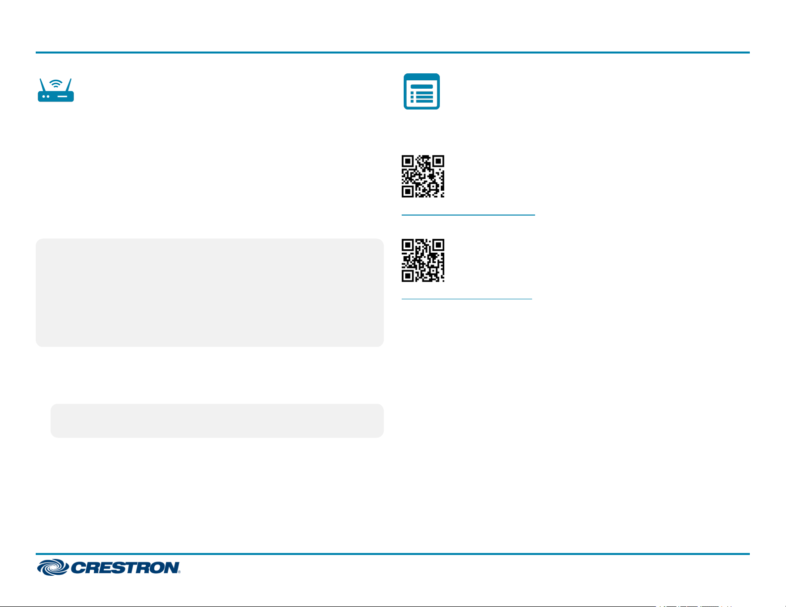
Visit the Product Page
Scan the QR code to visit the product page.
MC4:
www.crestron.com/model/6510432
MC4-I:
www.crestron.com/model/6511326
NOTE:Acquire mode deactivates after one hour by default. This
timeout period can be modified in Crestron Toolbox.
2. Place the infiNET EX or ER device within range of the gateway (50 ft),
and put it into Acquire mode as described in its documentation. The
device is acquired within two minutes of putting it into Acquire mode.
3. Repeat step 2 for each device that must be acquired.
4. Press ACQUIRE on the control system to leave Acquire mode.
7
Page 8

MC4/MC4-I
Additional Information
Original Instructions
The U.S. English version of this document is the original instructions.
All other languages are a translation of the original instructions.
Crestron product development software is licensed to Crestron dealers and Crestron
Service Providers (CSPs) under a limited nonexclusive, nontransferable Software
Development Tools License Agreement. Crestron product operating system software is
licensed to Crestron dealers, CSPs, and end-users under a separate End-User License
Agreement. Both of these Agreements can be found on the Crestron website at
www.crestron.com/legal/software_license_agreement.
The product warranty can be found at www.crestron.com/warranty.
The specific patents that cover Crestron products are listed at
www.crestron.com/legal/patents.
Certain Crestron products contain open source software. For specific information, visit
www.crestron.com/opensource.
Crestron, the Crestron logo, Cresnet, Crestron Toolbox, Crestron XiOCloud, and
infiNETEX are either trademarks or registered trademarks of Crestron Electronics, Inc.
in the United States and/or other countries. The microSDlogo is either a trademark or
a registered trademark of SD-3C, LLC in the United States and/or other countries.
Wi-Fi is either a trademark or registered trademark of Wi-Fi Alliance in the United
States and/or other countries. Other trademarks, registered trademarks, and trade
names may be used in this document to refer to either the entities claiming the marks
and names or their products. Crestron disclaims any proprietary interest in the marks
and names of others. Crestron is not responsible for errors in typography or
photography.
Quick Start
©2020 Crestron Electronics, Inc.
Doc ID 8489A
(2054144)
01/03/20
8
 Loading...