

Page 1

Crestron Lighting
Control System
Design Guide
Page 2

This document was prepared and written by the Technical Documentation department at:
Crestron Electronics, Inc.
15 Volvo Drive
Rockleigh, NJ 07647
1-888-CRESTRON
All brand names, product names and trademarks are the property of their respective owners.
2003 Crestron Electronics. Inc.
Page 3

Crestron Lighting Control System
Contents
Lighting Control System Design 1
Introduction ...............................................................................................................................1
Types of Lighting System Designs............................................................................................ 1
Centralized Design ......................................................................................................2
Distributed Design....................................................................................................... 3
Complete Crestron Home Design................................................................................ 4
Requirements for Design ........................................................................................................... 5
Step 1: Define the Load Schedule ...............................................................................5
Step 2: Module Selection............................................................................................. 8
Step 3: Enclosure Selection....................................................................................... 12
Step 4: User Interface Selection ................................................................................14
Step 5: Wiring Plan ...................................................................................................23
Step 6: Control Processor Selection ..........................................................................24
Step 7: Network Block Selection...............................................................................28
Step 8: Accessories Selection.................................................................................... 29
Basic Lighting System Interconnections .................................................................................30
Ordering a Crestron Lighting Control System......................................................................... 31
Hardware ...................................................................................................................31
Programming............................................................................................................. 31
Example Lighting System........................................................................................................32
Merchandise Returns / Repair Service ......................................................................38
CRESTRON Limited Warranty.................................................................................38
Design Guide – DOC. 5999A Contents • i
Page 4

Page 5

Crestron Lighting Control System
Lighting Control System Design
Introduction
A lighting control system is as unique as the home it supports.
Crestron offers the equipment and flexibility of design required for every one-of-a-
kind solution to home automation needs. The designer can create a complete lighting
system consisting of traditional wiring with local intelligence, up to a system that
incorporates distributed, high-voltage wiring with centralized and/or distributed
intelligence. Cresnet low-voltage wiring is used for control throughout this wide
range of system design possibilities.
In a typical home with traditional wiring, a wall switch completes a simple circuit to
an overhead light. Adding additional lighting controls to the room requires that banks
of switches, dimmers, or timers replace the single switch.
In larger homes, businesses, and institutions, a multi-function user interface replaces
the large banks of traditional switches, dimmers, and timers. In addition to lighting,
these user interfaces can also be used to control security, HVAC, and audio/video
systems.
The system control can be located near the user interface, the controlled circuits, or
can be centralized at some other remote location.
Crestron D3 Pro software is a comprehensive design and development tool that
provides a programming environment for all lighting, HVAC and security needs. It
contains many features to facilitate a successful installation, including an
astronomical clock that allows the scheduling of events based on time of day or
sunrise and sunset. Keypads and touchpanels are easily designed and programmed,
and communication among Crestron control equipment is simplified.
Types of Lighting System Designs
Crestron offers centralized and distributed lighting control system components. A
centralized system is one in which all the high-voltage circuits are terminated within
a Crestron home automation enclosure. A distributed system is the traditional wiring
system of individual lighting circuits with local control. The most efficient lighting
systems are a combination of centralized processing and distributed dimmers. This
provides the reliability of local control along with sophisticated central control.
Design Guide – DOC. 5999A Lighting Control System Design • 1
Page 6

Control System Crestron Lighting
Centralized Design
The high-voltage lighting, fans, motors and switch circuits are individually wired
directly to the modules in the Crestron home automation enclosure. The modules are
controlled by low voltage user interfaces in the living area. This greatly simplifies
the high-voltage wiring while creating a flexible and efficient design using keypad
and touchpanel interfaces.
A central processor, connected via a local area network to the lighting modules and
the user interfaces, is dedicated to lighting, fans, motors, HVAC, and security. Other
processors that are dedicated to other home control systems can communicate via
Ethernet, RS-232 or RS-422 to the lighting processor. This eliminates the need for
additional controls for other home systems, separating home safety and life support
systems from information and entertainment systems, providing a flexible design
solution and a fully integrated home control.
Lighting Layout in a Centralized Design
2 • Lighting Control System Design Design Guide – DOC. 5999A
Page 7

Crestron Lighting Control System
Distributed Design
In the traditional distributed design wiring method, Crestron wall box dimmers can
be retrofitted into a project after routine high-voltage wiring is completed.
In addition to the traditional high-voltage wiring, a low-voltage communication wire
is run from the dimmer to the nearest Cresnet connection. This design offers the end-
user the familiarity of a traditional control coupled with the power and flexibility of
automated control. In a distributed design, the user has the security of operating the
lighting in the event of a temporary control system interruption.
Lighting Layout in a Distributed Design
Design Guide – DOC. 5999A Lighting Control System Design • 3
Page 8

Control System Crestron Lighting
Complete Crestron Home Design
A complete Crestron home design is a blend of distributed and centralized design in
which central control intelligence and distributed local dimmers form a reliable
whole house lighting control solution.
Large rooms, stairways, and frequently used rooms are often remotely controlled
using the astronomical time clock or whole-house presets. This level of control
requires connection to a central dimming controller. Each room is equipped with a
low voltage keypad for preset selection and audio/video integration. All the dimmers
in the system (grouped into the central controller for wiring convenience)
communicate with each other through the Crestron control system, providing a
complete Crestron home design.
Lighting Layout in a Complete Crestron Home Design
4 • Lighting Control System Design Design Guide – DOC. 5999A
Page 9
Crestron Lighting Control System
Requirements for Design
Lighting system design begins with a collection of complete information. The
successful lighting system plan begins with a lighting load schedule that you define
and compile based on the information contained in a detailed floor plan that
identifies the elements of the load schedule design, the location and types of user
interfaces used (i.e., local dimmers, keypads or touchpanels), the control processor
details (large systems should use a dedicated lighting control processor), and the
optional window treatment details, which include shade/blind motors and relay
control (consult manufacturer for details). The following eight steps, performed in
this sequence, is the recommended design procedure.
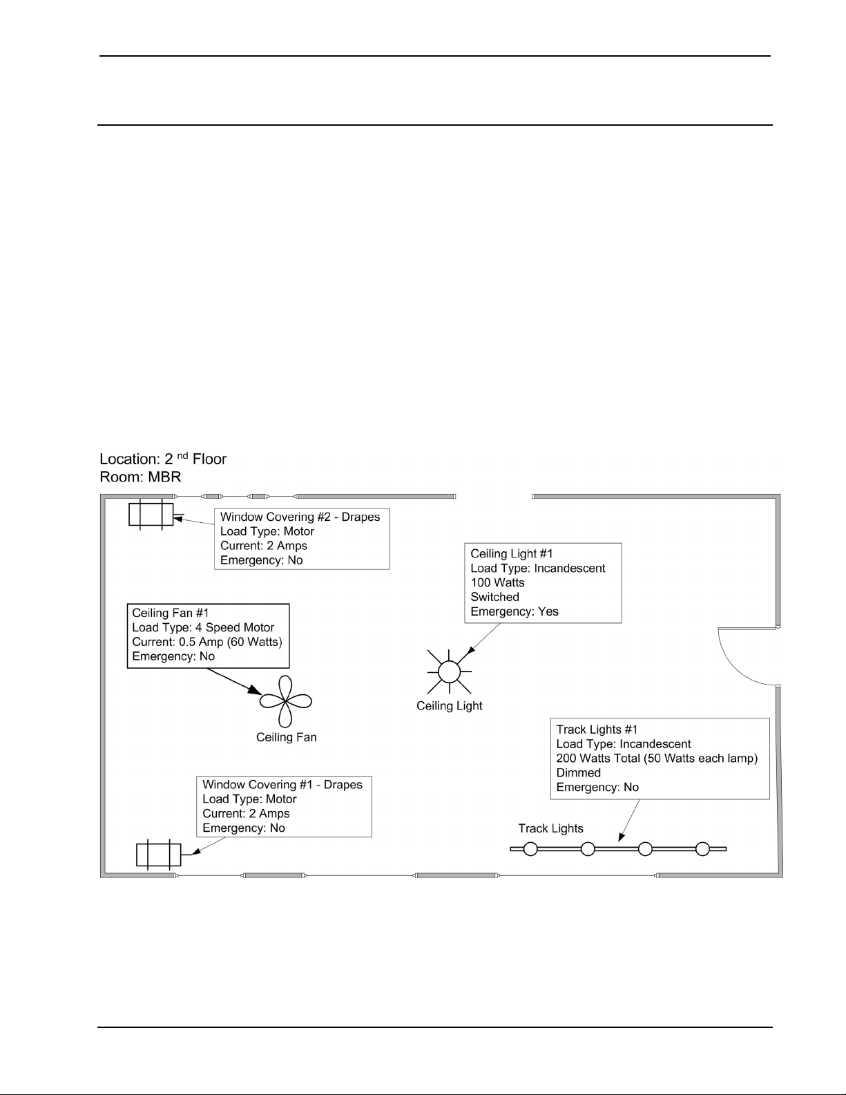
Step 1: Define the Load Schedule
A load schedule lists the information on each load connected to every circuit in an
electrical panel. This is the primary source of information required for lighting
control system design.
Simplified Room Specifications Example
Design Guide – DOC. 5999A Lighting Control System Design • 5
Page 10
Control System Crestron Lighting
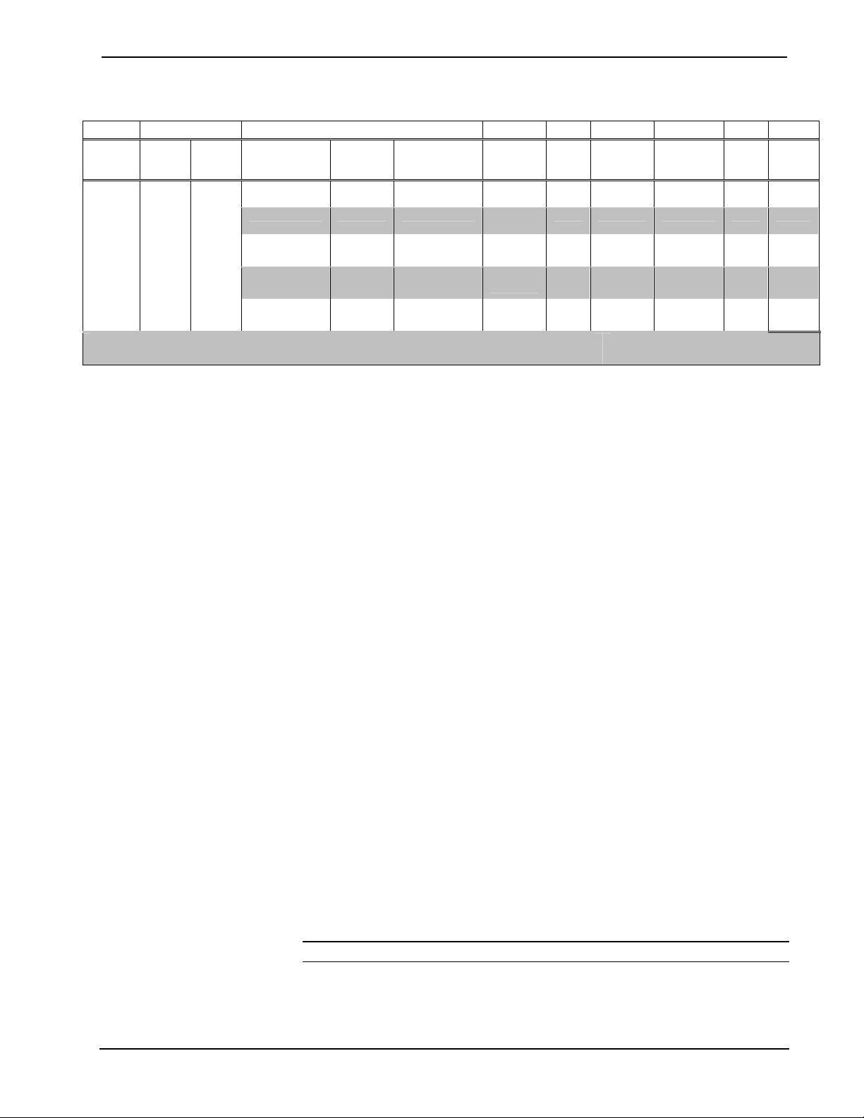
Example of a Load Schedule (Based on the room example in the previous illustration)
1 2 3 4 5 6 7 8 9
Control
Zone
1 Floor 2 MBR
Area Room Controlled Circuit
name
Ceiling 1 Ceiling Light Incan-
Track 2 Track Light Incan-
Ceiling Fan 3 Ceiling Fan Ceiling
Drape Motor 1 4 Drape Motor 1 3-wire
Drape Motor 2 5 Drape motor 2 3-wire
Controlled
Load Schedule Items
1. Control Zone: Controlled circuits that are not physically wired together, but
Circuit
Number
Fixture Type Load Type DIM Emergency
Lighting?
N Yes 100/120 1 100
descent
Y No 50/120 4 200
descent
N No 60/120 1 60
Fan
N No 240/120 1 240
Motor
N No 240/120 1 240
Motor
Total Wattage For Floor 2 MBR 840
Fixture
Wattage and
Voltage
Fixture
Qty
always operating in tandem. For example, perimeter lights, sconce lights
and overhead lights all operating together.
Total
Watts
2. Location of controlled lighting zone, relevant to building site/drawings,
floor designation, and room name.
3. Fixture and/or lamp type of controlled lighting zone, including any
information describing custom fixtures, undetermined fixtures, dimmable
transformers or fluorescent ballasts, and circuit breaker numbers. This
information can also contain the number assigned to the controlled circuit.
4. Load Type of the controlled lighting zone. Load types include incandescent,
magnetic low voltage, electronic low voltage, neon/cold cathode, HID,
dimmable/non-dimmable fluorescent ballast, ceiling fans, and switched 3wire motor circuits. This information is especially important for selecting
the correct Crestron module power rating and type.
5. Dimming requirement for the controlled lighting zone (i.e. whether the
lighting level of the loads/fixtures needs to be ramped up/down or simply
switched on/off). Indicate: “Yes” for Dimming, and “No” for Non-Dim.
6. Emergency designation for the controlled lighting zone (Yes/No; i.e. when
a load also needs to be assigned to a separate emergency power feed). These
items are assigned to their own separate dimmer, so it can be fed with
emergency power.
7. Fixture Wattage (Watts or Power-Rating per Fixture) with regard to the
controlled lighting zone. This is used to determine the number of fixtures
that can be powered per each Crestron Dimmer Module channel, in order
not to overload the dimmer beyond it’s own power rating. Volts rating for
the controlled lighting zone tells the designer the voltage of the electrical
feeds required for that zone, and hence the required rating for the associated
Crestron module. It is recommended, due to electrical codes, to avoid
mixing different voltages in a single enclosure.
NOTE: At the present time, all Crestron load voltage is 120 VAC.
6 • Lighting Control System Design Design Guide – DOC. 5999A
Page 11

Crestron Lighting Control System
8. Quantity of fixtures for the controlled lighting zone. This is useful, along
with item #6, in calculating the total power rating (watts) for that particular
controlled circuit (item #9).
9. Total Wattage, or Power Rating, of the controlled lighting zone. This is
required in order to determine the total number of Crestron Lighting
Module channels required for that particular zone, especially if the load of
the total number of fixtures exceeds the rating of a single module channel.
NOTE: National and local electrical codes and the functionality of each userinterface must be taken into consideration. Always install electrical devices
according to the national Electrical Code (NEC), local codes, and with safety in
mind.
Equipment List Specification
The equipment list is based on the requirements collected for the lighting system in
the load schedule. This is a sequential step-by-step process. The information
gathered in previous steps is required to complete following steps. Once all the steps
are completed, a complete bill-of-material for the system is created. The seven steps
are as follows:
• Module selection – based on the number and type of loads
• Enclosure selection – based on the number of modules and
locations
• User interface selection – based on the user control requirements
• Wiring plan – based on the previous steps and the layout of the
environment
• Control processor – based on the size of the system (large systems
should have a dedicated processor)
• Network block selection – based on the layout and distribution of
the loads
• Accessories selection – based on the required accessories (third
party telephone and alarm systems, etc.)
NOTE: Crestron D3 Pro software is the ideal tool for specifying an equipment list.
A fully documented help file supports the easy-to-use screens and views. It offers the
designer a starting place for determining modules and enclosures. The Crestron D3
Pro software can also generate a load schedule report. Refer to the latest version of
the Crestron D3 Pro Reference Guide (Doc. 5998) available from the Crestron web
site (www.crestron.com) for detailed information about D3 Pro.
Design Guide – DOC. 5999A Lighting Control System Design • 7
Page 12

Control System Crestron Lighting
Step 2: Module Selection
The enclosure mounted Crestron modules, connected to the appropriate terminal
block, perform pre-determined functions with various types of light sources, motors
and non-lighting loads. Modules have a Cresnet link for control processor
communication and a module override connection. Six different modules are
available. The type of load, number of circuits, required current load capacity, and
economic considerations are all determining factors when choosing modules. The
number and type of modules is determined from the load schedule. The number of
required modules will determine the size and type of enclosure(s) in the next step.
Each module is wired via the terminal block to a circuit breaker (provided by others).
The power provided to the module is distributed to all of its outputs. Each module
contains relays that provide an individual air gap for each controlled high voltage
circuit. Module selection can be done manually or by the D3 Pro software.
NOTE: A module terminal block (CLT-Series device) must also be ordered for each
module. The corresponding CLT terminal block is installed in the enclosure for high
voltage wire termination. Each terminal block includes a terminal rail for mounting
the terminal block in the enclosure. Terminal rails and blocks do not occupy a
module space within an enclosure.
CLX-2DIM2 Module Specifications
Oversized heat-sink fins on the face of the module provide superior heat dissipation,
eliminating heat related failures. The modules incorporate spit-bobbin transformers
and ground reference electronics for superior performance. AC line noise
interference and lamp flicker are eliminated by an innovative zero-crossing detection
technique and unique Crestron firmware. The red LEDs on the side of the module
indicate the presence of voltage to the module output. The brightness of the LED
corresponds to brightness of the lights. The green and amber Cresnet
communications LEDs indicate both power and communication.
Module Specifications
CLX-2DIM2 has two input feeds and two large capacity dimmers. This module
handles larger loads like chandeliers, landscape lights, and loads using many
transformers or 2-wire ballasts. Each output circuit is limited to 1920 watts (16A).
Load Type Incandescent, magnetic low-
voltage, neon and cold cathode
lighting, and 2-wire fluorescent
ballasts
Module Output 2 controlled circuits, 16A per
controlled circuit, 32A total
Heat Dissipation
Terminal Block
Input Voltage
Size (H x W x D)
Temperature Range
Humidity Range
Weight
170 BTU/Hr (with full load)
CLT-2DIM2
Two 120 VAC 60 Hz, singlephase (same phase)
7 3/8 x 6 7/8 x 3
32 – 104° F
10 – 90% RH (non condensing)
3 lbs.
8 • Lighting Control System Design Design Guide – DOC. 5999A
Page 13

Crestron Lighting Control System
CLX-1DIM4 is a workhorse module with one input feed and four controlled
dimmers. Ideal for a small mix of loads where some loads are 500W or more. The
single input feed limits the total output of all four controlled dimmer circuits to 1920
watts (16A).
CLX-1DIM4 Module Specifications
Load Type Incandescent, magnetic low-
voltage, neon and cold
cathode lighting, and 2-wire
fluorescent ballasts
Module Output 4 controlled circuits,16A per
controlled circuit, 16A total
Heat Dissipation
Terminal Block
Input Voltage
Size (H x W x D)
Temperature
Range
Humidity Range
Weight
98 BTU/Hr (with full load)
CLT-1DIM4
120 VAC 60 Hz, single-phase
7 3/8 x 6 7/8 x 3
32 – 104° F
10 – 90% RH (non
condensing)
3 lbs.
CLX-1DIM8 Module Specifications
CLX-1DIM8 is best used for multiple small incandescent loads. It is economical to
use only six or seven channels on the module with small loads, while leaving some
channels unconnected. The single input feed limits the total output of all eight
controlled dimmer circuits to 1920 watts (16A).
Load Type Incandescent, magnetic low-
voltage, neon and cold cathode
lighting, and 2-wire fluorescent
ballasts
Module Output 8 controlled circuits, 16A per
controlled circuit, 16A total
Heat Dissipation
Terminal Block
Input Voltage
Size (H x W x D)
Temperature
101 BTU/Hr (with full load)
CLT-1DIM8
120 VAC 60 Hz, single-phase
7 3/8 x 6 7/8 x 3
32 – 104° F
Range
Humidity Range
Weight
10 – 90% RH (non condensing)
3 lbs.
Design Guide – DOC. 5999A Lighting Control System Design • 9
Page 14

Control System Crestron Lighting
The CLX-4HSW4 switching module can switch four 16A lighting circuits as well as
½ HP (maximum) motors. Loads are switched on and off, but not dimmed. The
maximum load is four controlled circuits per module and 1920 watts (16A) per
controlled circuit (64A maximum total).
CLX-4HSW4 Module Specifications
Load Type INC, MLV, NCC and non-dim
fluorescent, non-dim H.I.D.
Module Output 4 controlled circuits, 16A (1/2
HP) per controlled circuit, 64A
total
Heat Dissipation
Terminal Block
Input Voltage
Size (H x W x D)
Temperature Range
Humidity Range
Weight
42 BTU maximum
CLT-4HSW4
Four 120 VAC 60 Hz, singlephase (same phase)
7 3/8 x 6 7/8 x 3
32 – 104° F
10 – 90% RH (non condensing)
3 lbs.
CLX-1MC4 Module Specifications
The CLX-1MC4 controls up to four 10A (½ HP) maximum bi-directional motors.
High-voltage window treatment motor controls are assigned to CLX-1MC4. The
single input feed limits the total output of all eight controlled dimmer circuits to
1920 watts (16A).
Load Type
Module Output 4 controlled circuits,
Heat Dissipation
Terminal Block
Input Voltage
Size (H x W x D)
Temperature Range
Humidity Range
Weight
3-wire bi-directional motors
10A (1/2 HP) per motor load (5A
each direction), 16A total
22 BTU/Hr
CLT-1MC4
120 VAC 60 Hz,
single-phase
7 3/8 x 6 7/8 x 3
32 – 104° F
10 – 90% RH (non condensing)
3 lbs.
10 • Lighting Control System Design Design Guide – DOC. 5999A
Page 15

Crestron Lighting Control System
T
L
l
i
T
r
t
G
g
The CLX-1FAN4 controls up to four independent ceiling fans with four preset
speeds in addition to off. The maximum load is four 2A ceiling fans motors per
module. Lights for ceiling fans are assigned to a DIM type module and are wired
independently.
CLX-1FAN4 Module Specifications
Load Type
Module Output 4 controlled circuits, 2A per
Terminal Block
Input Voltage
Size (H x W x D)
Temperature
Range
Humidity Range
Weight
Ceiling fan (1 per controlled circuit)
controlled circuit, 8A total
4 speeds plus off.
CLT-1FAN4
120 VAC 60 Hz,
single-phase
7 3/8 x 6 7/8 x 3
32 – 104° F
10 – 90% RH (non condensing)
3 lbs.
Terminal Blocks (CLT-Series)
he Crestron terminal block is mounted within an enclosure and has two functions.
1. Terminates the circuit feed (HOT and NEUTRAL) supplied by circuit
breaker and distributes the controlled circuits (LOAD) to the fixtures.
2. Serves as a test point and interface to the lighting module. Bypass
jumpers on the terminal block allow the testing of circuits and protect
the module during installation.
eft and right wiring labels are provided with each terminal block. The wiring
abels are positioned in between the terminal block and enclosure to provide
dentification of each terminal block section.
he left-side labels are common for both single and double-width enclosures. The
ight-side labels are only used in double-width enclosures because the modules and
erminal blocks along the right side must be inverted when installed.
rounding terminal blocks (provided with the CAEN enclosures) permit the
round wire termination.
CLT-Series Specifications
Item Specification
Line Voltage Wiring
Terminal Block
Grounding Terminal
Block
Use copper conduct ors only – rated 75° C
Accepts one 14 to 10 AWG wire. Wires should be
stripped to ½ inch. Tighten terminal blocks to 9 in/lbs
14 to 10 AWG – Tighten to 35 in/lbs
8 AWG – Tighten to 40 in/lbs
6 to 4 AWG – Tighten to 45 in/lbs
Design Guide – DOC. 5999A Lighting Control System Design • 11
Page 16

Control System Crestron Lighting
Step 3: Enclosure Selection
Crestron home automation enclosures contain the control devices of the lighting
control system (excluding the user interfaces). These enclosures also provide a
centralized location in which to install other home automation equipment. Crestron
enclosures are constructed of 16-gauge galvanized steel and are UL and C-UL listed.
Enclosures can be flush mounted or surface mounted.
The wide range of sizes, mounting options, and convenient electrical knockouts,
ensure mounting location flexibility, efficiency and an orderly installation.
NOTE: CAEN-Series enclosures are required to install CLX-Series lighting
modules.
The lighting designer identifies the CAEN-Series enclosure(s) required, based on the
number of module spaces counted in step 2 and the AC power distribution of the
system. Enclosures may be all centrally located in one area or distributed throughout
the home. Distributing the enclosures throughout the home reduces the run-length of
high-voltage wires to the loads.
Enclosures have a specific number of module spaces for CLX-Series modules, the
control processor, and CAEN-UMP mounting plates.
Enclosures that do not contain a PAC2 control processor require a CAEN-BLOCK
communications link, which is installed in the bottom of the enclosure and not
installed in a module slot. Therefore the CAEN-BLOCK is not included in the
calculation of enclosure size.
Consider selecting enclosures with excess room to accommodate system
improvements and expansion. Crestron recommends selecting an enclosure that has
at least one more space than needed, allowing for changes in modules or lighting
fixtures. A larger enclosure also enhances air-cooling.
The CAEN-7x2 is the largest and most economical enclosure, containing up to 12
modules and a PAC2 processor. Without the PAC2, this enclosure can hold up to 14
modules (assuming a fully loaded enclosure with 14 CLX-1DIM8s, a maximum of
112 dimmers).
There are occasions when a separate enclosure is desired for the PAC2. The
processor can be located in a more accessible location with better temperature
control and easier access to the wiring. In this situation, Crestron recommends using
the CAEN-2x1 enclosure for the PAC2.
Single-width enclosures fit between 16” on-center stud framing. Using several
CAEN-7x1 enclosures, flush mounted between the studs, creates a clean, in-wall
installation. When surface mounting the enclosures, allow at least 6” (15cm) side-toside clearance between enclosures.
The design of the CAEN-Series enclosures separates high-voltage and low-voltage
wiring when the control processor is installed. The low-voltage openings in the
bottom of the enclosure are insulated to protect low-voltage wires from cuts and
scrapes. The airflow through the perforated cover assists in the dissipation of heat.
Refer to the following tables for a listing of dimensions and maximum number of
modules that can be contained in each CAEN-Series enclosure.
12 • Lighting Control System Design Design Guide – DOC. 5999A
Page 17

Crestron Lighting Control System
CAEN-Series Specifications
CAEN Specifications 7x2 7x1* 4x2 4x1* 2x1*
Module Capacity
Required Flush Mount
25 ½” x 62” 14 ⅜” x 62” 25 ½” x 38 ⅞” 14 ⅜” x 38 ⅞” 14 ⅜” x 23 ½”
Opening (W) x (H)
Construction
Regulatory Approvals
Mounting
CAEN-Series Dimensions (Front and Side Views)
W1
W3
W6
H2
H3
W3
W2
W4
H1
W5
14 7 8 4 2
16 gauge galvanized sheet metal
Cover is painted metal with ventilation holes
UL and C-UL listed
Surface or flush mounted
*Single-width enclosures fit between standard 16” on-center studs
CAEN
Dimensions
1
H1
H2
H3
W1
W2
W3
W4
W55
W6
D1
Cover Thickness
Cover Height
Cover Width
Weight2 Empty3
Weight Full4
D1W3
1. Length is in inches.
2. Weight is in pounds.
3. Weight Empty includes the cover.
4. Weight Full is with the maximum number of modules installed.
5. The lower keyholes are not symmetrically spaced in single-width enclosures.
7x2 7x1 4x2 4x1 2x1
62 38 ⅞ 23 ½
2 11/16 2 ⅛
56 32 ⅞ 34 18 ⅝
26 ½ 15 ⅜ 26 ½ 15 ⅜
25 ½ 14 ⅜ 25 ½ 14 ⅜
2 ½ 1 ¾ 2 ½ 1 ¾
20 ½ 10 ⅞ 20 ½ 10 ⅞
20 ½ 9 ⅞ 20 ½ 9 ⅞
2 ½ 2 ¾ 2 ½ 2 ¾
4 ⅛
1
/16
62 ¾ 39 ⅝ 24 ¼
27 ¼ 16 ⅛ 27 ¼ 16 ⅛
65 42 43 28 19
155 88 95 55 31
Design Guide – DOC. 5999A Lighting Control System Design • 13
Page 18

Control System Crestron Lighting
Step 4: User Interface Selection
User interfaces (keypads, dimmers, switches, and touchpanels) provide the link
between the control devices in the enclosure and the user. Typically these interfaces
are prominently and strategically located throughout a lighting design.
NOTE: Due to the variety of touchpanels, dimmers, switches and keypads,
specifications for each type are not provided as part of this guide. Instead obtain the
latest copy of the individual operation guide from the Crestron website
(www.crestron.com).
The lighting designer specifies the type of user interface required for each location,
based on function and user preference.
Keypads, touchpanels, dimmers and switches are available in a wide variety of
choices, including number of buttons, color of trim, color of the buttons, back
lighting and even custom engraving on each button.
The entire line of award-winning Crestron touchpanels can be used to enhance the
most demanding design.
C2N-DB Series Wall Panels
The C2N-DB6/8/12-series Decorator Wall Panels are wall-mounted, single-gang
user interfaces that can be part of a Crestron solution. The panels are standard
Cresnet devices providing fingertip control when the control system is properly
programmed using Crestron’s SIMPL Windows, Application Builder, or D3 Pro
software. The number in the product’s name corresponds to the number of buttons on
the panel. Each of these panels is available in three colors: almond, black, and white.
A letter at the end of the product name, ‘A’, ‘B’, or ‘W’, denotes the color; e.g.,
C2N-DB12B is a black, 12-button unit.
Faceplates are not supplied; the wall panels accept decorator style faceplates that can
be obtained in any store selling lighting supplies and accessories, making it easy for
the wall panels to match the appearance of the site’s other switch and outlet styles.
Custom-engraved keys can be designed and obtained by using the Crestron Engraver
software. Version 2.1.0.1 or later is available from the Downloads | Software
Updates section of the Crestron website (www.crestron.com).
All buttons on the wall panel are functionally identical and have light emitting diodes
(LEDs) that serve as user feedback indicators. Each LED’s illumination (on/off) is
independently addressable, and is programmable using SIMPL Windows. The
intensity level for the button LEDs can be set from 0 to 100%.
14 • Lighting Control System Design Design Guide – DOC. 5999A
Page 19

Crestron Lighting Control System
6, 8, and 12 button C2N-DB Series Wall Panels
Physical View of the C2N-DB Wall Panel
Side View
with buttons installed
1.53 in
(3.89 cm)
1.07 in
(2.72 cm)
4.16 in
(10.57 cm)
Front View
with buttons removed
1.79 in
(4.55 cm)
Rubber
Membrane
Back View
1.67 in
(4.24 cm)
2.70 in
(6.86 cm)
Cresnet
port
Design Guide – DOC. 5999A Lighting Control System Design • 15
Page 20

Control System Crestron Lighting
CNX Series Keypads
Crestron keypads are a wall-mounted user interface. The keypads feature oversized
buttons that provide positive feedback. The user can have the ability to control
individual lights or groups of lights and create a predetermined “lighting scene” for
particular activities. Keypads are Cresnet devices and programmable using SIMPL
Windows or the Crestron D3 Pro software. The product name corresponds to the
number of keypad buttons. For example, CNX-B6 is a six-button keypad and a
CNX-B12 is a 12-button keypad.
The CNX-B series keypads have a uniquely stylish shape and faceplates are
available for the most common groupings; single, double, or three gang plate
arrangements. Keypads are available with the following features:
• Available with 2, 4, 6, 8, or 12 buttons.
• Colors include white, almond, or black.
• Metal faceplate options:
- Black Chrome - Brushed Gold
- Polished Black - Polished Gold
- Polished Brass - Stainless Steel
• Primed faceplate available.
• All keypads can be custom engraved.
• All keypad buttons are backlit capable and have an LED that serves as a
user feedback indicator. Status LEDs are controlled via SIMPL
programming or the Crestron D3 Pro software. The illumination of each
LED is independently addressable and programmable. Each LED can be
programmed to dim at night and return to full intensity during the day.
• Each keypad requires 3 watts of power.
• Crestron keypads can be ganged in one, two or three gang configurations
and are mounted in standard electrical junction boxes. Custom multi-gang
plates are required.
Physical View of the CNX-B12 Keypad
1.07 in
(2.71 cm)
4.76 in
(12.10 cm)
2.91 in
(5.57 cm)
1.54 in
(3.90 cm)
16 • Lighting Control System Design Design Guide – DOC. 5999A
Page 21

Crestron Lighting Control System
Wall Dimmers
The CLW-DIM is a stand-alone wall box dimmer that can also act as a Cresnet
device that reports to a Crestron control processor. The CLW-DIM has four preset
lighting levels that can be adjusted (refer to note below). The CLW-DIM also
includes two isolated, non-polarized Cresnet wires (plus a ground wire) for
connecting to the Cresnet network over a twisted pair wire with shield.
NOTE: The four preset levels are noted as Button 1-High, Button 1-Low, Button
Preset 2, and Button Preset 3. Preset “Button 1-High” is usually used for turning
lights on to full brightness while preset “Button 1-Low” is usually used for turning
the lights off. Although “1-High” and “1-Low” are usually used for “On” and “Off”
respectively, the light level for each preset can be customized by the user. Refer to
the CLW-DIM, DIMS, & SLVD Operation Guide (Doc. 5995) for more information
on installation and customizing light levels.
The CLW-DIM features a three-position mode selection switch. In the absence of
Cresnet communications, the dimmer can still be used to control lighting.
The CLW-DIMS is similar to the CLW-DIM with the added capability of working
with a slave unit
The CLW-SLVD is a slave unit that when used in conjunction with the CLW-DIMS
acts as an additional dimmer control point in a multi-dimmer / single circuit
application. It does not connect to a Cresnet system and cannot be used without a
CLW-DIMS. The CLW-SLVD does not have a mode selection switch and is not
programmable. It emulates the operation of the CLW-DIMS to which it is connected.
The CLW-DIM, CLW-DIMS, and CLW-SLVD are available in white (designated by
part numbers ending in “W”), almond (designated by part numbers ending in “A”,
and black (designated by part numbers ending in “B”). Each dimmer can be covered
with a decorative faceplate (not supplied).
The CLW-DIM, CLW-DIMS, and CLW-SLVD mount in a standard wallbox and are
covered using a decorator-style faceplate (not included).
CLW-DIM, CLW-DIMS, & CLS-SLVD Specifications
SPECIFICATION DETAILS
Power Requirements Line Power (120 VAC, 60 Hz)
Load Type Incandescent, Tungsten-Halogen, Magnetic Low Voltage
Load Ratings
Incandescent/Tungsten Halogen 1000 W (800 W)
Magnetic Low Voltage 1000 VA / 750 W (800 VA / 600 W)
Operating Temperature and
Humidity
32°F to 104°F (0°C to 40°C)
10 to 90% Relative Humidity (Non-Condensing)
NOTE: VA ratings are for input power to the transformer. If you do not know the
input power requirement of the transformer, use the bulb’s wattage rating to
determine proper rating.
NOTE: Operating temperature affects load ratings. Refer to the Load Rating
specification in the table above for specific operating temperatures. Ratings are given
for 32°F to 86°F (0°C to 30°C) and 32°F to 104°F (0°C to 40°C) operation. Ratings
for 32°F to 104°F (0°C to 40°C) are in parentheses.
Design Guide – DOC. 5999A Lighting Control System Design • 17
Page 22

Control System Crestron Lighting
Derating
In a multi-gang installation, several dimmers are grouped in one horizontal wall box.
When this is the case, the inner heat sink section is removed to permit the installation
of a one-piece multi-gang wallplate. Removing the heat sink reduces the current
carrying capability of the dimmers due to reduced heat dissipation. The following
table provides the derating information for this application.
Application No Heat Sink Removed
– Single Unit
One Heat Sink Removed
– Two Gang
Both Heat Sinks Removed
– Three or more Gang
Incandescent and Tungsten
Halogen
Magnetic Low Voltage 1000 VA / 750 W
1000 W (800 W) 600 W (450 W) 400 W (300 W)
(800 VA / 600 W)
For additional installation information, refer to the CLW-DIM, DIMS & SLVD
Installation Guide (Doc. 5995).
Physical View of CLW-DIM and CLW-DIMS (clockwise from top; Top, Side, and Front)
600 VA / 450 W
(450VA / 300 W)
400 VA / 300 W
(300 VA / 200 W)
18 • Lighting Control System Design Design Guide – DOC. 5999A
Page 23

Crestron Lighting Control System
Physical View of CLW-SLVD (clockwise from top; Top, Side, and Front)
Design Guide – DOC. 5999A Lighting Control System Design • 19
Page 24

Control System Crestron Lighting
Switches
The CLW-SW wall box switch can also act as a Cresnet device reporting to a
Crestron control processor. The CLW-SW includes two isolated, non-polarized
Cresnet wires (plus a ground wire) for connecting to a Cresnet system over a twisted
pair wire with shield. In the absence of Cresnet communications, the switch can still
be used to control a load.
Refer to the CLW-SW, CLW-SWS, & CLS-SLVS Installation Guide (Doc. 6134)
for more installation information.
The CLW-SWS is similar to the CLW-SW with the added capability of working
with a slave unit (CLW-SLVS) in a multi-switch / single circuit application.
The CLW-SLVS is a slave unit that when used in conjunction with the CLW-SWS
acts as an additional switch control point in a multi-switch / single circuit
application. It does not connect to a Cresnet system and cannot be used without a
CLW-SWS. The CLW-SLVS does not have a mode selection switch and is not
programmable. It emulates the operation of the CLW-SWS to which it is connected.
The CLW-SW, CLW-SWS, and CLW-SLVS are available in white (designated by
part numbers ending in “W”), almond (designated by part numbers ending in “A”),
and black (designated by part numbers ending in “B”). These switches can be
covered with a decorative faceplate (not supplied).
CLW-SW, CLW-SWS, & CLS-SLVS Specifications
SPECIFICATION DETAILS
Power Requirements Line Power (120 VAC, 60 Hz)
Switch Type Single-Pole, Single-Throw
Load Type Incandescent, Tungsten Halogen, Fluorescent,
Load Ratings
Incandescent / Tungsten Halogen 1000 W (800 W)
Magnetic Low Voltage 1000 VA / 750 W (800 VA / 600 W)
Neon / Cold Cathode 1000 VA / 750 W (800 VA / 600 W)
Electronic Low Voltage 1000 W (800 W)
Fluorescent / HID
(High Intensity Discharge)
General Purpose Fan 3.0 A (3.0 A)
Minimum Load 40W / 0.5A
Operating Temperature and Humidity 32°F to 104°F (0°C to 40°C)
Electronic Low Voltage, Magnetic Low Voltage,
General Purpose Fan
8 A (6.5 A)
10 to 90% Relative Humidity (Non-Condensing)
NOTE: VA ratings are for input power to the transformer. If you do not know the
input power requirement of the transformer, use the bulb’s wattage rating to
determine proper rating.
NOTE: Operating temperature affects load ratings. Refer to the Load Rating
specification in the table above for specific operating temperatures. Ratings are given
for 32°F to 86°F (0°C to 30°C) and 32°F to 104°F (0°C to 40°C) operation. Ratings
for 32°F to 104°F (0°C to 40°C) are in parentheses.
20 • Lighting Control System Design Design Guide – DOC. 5999A
Page 25

Crestron Lighting Control System
NOTE: Refer to the latest version of the Installation Guide (Doc. 6134) for derating
information in multi-gang applications, available on the Crestron website,
www.crestron.com.
Physical View of CLW-SW/SWS (clockwise from top; Top, Side, and Front)
Physical View of CLW-SLVS (clockwise from top; Top, Side, and Front)
Design Guide – DOC. 5999A Lighting Control System Design • 21
Page 26

Control System Crestron Lighting
Touchpanel Selection
CT-1000
TPS-2000L
Crestron touchpanels are graphical user interfaces that provide the user with visual
control and feedback.
Touchpanels are an elegant, efficient and practical solution to room control. A
touchpanel can control lighting, audio and video, HVAC, and security.
Touchpanel pages can provide convenient control of every individual light in the
residence from a single location. The integration of touchpanels and lighting control
is a primary feature of Crestron lighting systems. The designer can create a complex
control environment while presenting the user with easy and intuitive controls.
For example, a "Good Night" button can be programmed to dim the lights, gently
quiet the music, notify the alarm system, and set a nighttime temperature. All with
one touch.
Designed using VT-Pro-e software, these user interfaces can be customized to
provide complete control of the lighting control system and the entire home
automation system.
Consult lightingsolutions@crestron.com
Physical Views of Series 1000 Touchpanel
4.86 in
(12.34 cm)
4.76 in
(12.10 cm)
for additional information.
1.59 in
(4.04 cm)
1.36 in
(3.47 cm)
22 • Lighting Control System Design Design Guide – DOC. 5999A
Page 27

Crestron Lighting Control System
Physical Views of TPS-2000L Touchpanel
3.43 in
(8.71 cm)
3.07 in
6.73 in
(17.10 cm)
4.76 in
(12.10 cm)
(7.79 cm)
Crestron touchpanels are available as either wired or wireless units, with screens
from 3.8” diagonal to 15” diagonal. Many Crestron touchpanels also feature buttons
that can be custom engraved and programmed to provide quick access to
programmed functions. The built-in speakers can play .WAV files provided by the
programming.
Step 5: Wiring Plan
The wiring plan includes all enclosures and the interconnecting wiring.
The designer determines the location of the enclosure(s), the route of keypad and
touchpanel connections to the enclosure(s), the route of the interconnecting cable
from the processor to the other enclosure(s), and the high voltage load routes to the
enclosure or dimmer.
Ensure there are enough connectors and power (PAC2 offers 50W) in the main
enclosure for all the user interfaces. Each enclosure filled with dimmers is connected
to the main enclosure and processor using low voltage wire. Dimmer enclosures are
distributed as needed.
Design Guide – DOC. 5999A Lighting Control System Design • 23
Page 28

Control System Crestron Lighting
Wiring Plan Details
Location Device Type Crestron Device
Room 1 DIM1 – Wall dimmer – 100 Watts CLW-DIM
Room 2 DIM4 – Wall dimmer – 150 Watts CLW-DIM
Room 2 DIM5 – Wall dimmer – 150 Watts CLW-DIMS
Room 2 SW1 – Wall Box switch – Low voltage/outdoor CLW-SW
Room 2 Touchpanel TPS-1000
Room 3 DIM2 – Wall dimmer – 100 Watts CLW-DIM
Room 3 DIM3 – Wall Dimmer – 100 Watts CLW-DIMS
Room 4 DIM6 – Wall dimmer – 200 Watts CLW-DIM
Room 5 DIM7 – Wall dimmer – 120 Watts CLW-DIM
Room 5 KP1 – Wall Keypad – Fan Motor Speed CLX-1FAN4
Step 6: Control Processor
The PAC2 has been specifically designed for the Crestron automation enclosure and
the Crestron lighting system, although other Crestron processors can also be used.
The PAC2 can be placed in its own enclosure for simplification of low-voltage
wiring. The PAC2 occupies one module space in single-width enclosures and two
module spaces in double-width enclosures.
24 • Lighting Control System Design Design Guide – DOC. 5999A
Page 29

Crestron Lighting Control System
)
The PAC2 processor provides 50W of power for keypads and touchpanels. Each
keypad in the CNX-B series uses 3-watts, therefore only 15 keypads can be
connected without adding another power supply. Make sure there is sufficient power
in the system design to accommodate all the keypads, touchpanels, voltage drops,
and wire runs. Additional power supplies should not be mounted on CAEN-UMP
plates in an enclosure that contains dimmer units because this introduces low-voltage
in the high-voltage section of the enclosure. If required, an extra power supply,
attached to a CAEN-UMP plate, can be added to a separate CAEN enclosure.
Crestron recommends the C2N-SPWS300 Power Supply; a 300-watt system power
supply designed for large Cresnet control systems. It operates with an input of 100 to
240 VAC, 4A (maximum) and a noise rating less than 150mV. The C2N-SPWS300
provides regulated 24 VDC, 300 W to Cresnet system components. The C2NSPWS300 is capable of delivering a nominal 75 watts of power at 24 volts DC on
any of its eight channels.
The PAC2 connects all the user interfaces:
• Keypads and wall switches
• touchpanels
• contact closures
• emergency switches
• override switches
• backup Cresnet controller input
• output relays
• fault indicator
• computer data port
The PAC2 enables the customer to efficiently control not only the lighting in their
home, but also other systems such as HVAC and security.
Physical View of the PAC2
Top View
24 Y Z G 24 Y Z G 24 Y Z G 24 Y Z G
24 Y Z G 24 Y Z G 24 Y Z G 24 Y Z G
24 Y Z G 24 Y Z G 24 Y Z G 24 Y Z G
24 Y Z G 24 Y Z G 24 Y Z G 24 Y Z G
I/O
S4
1 2 3 4 5 6 7 8 G
NET A
NET B
NET E
NET F
OVER
RIDE
(35.56 cm)
LEFT
BACKUP
NET INPUT
24 Y Z G
14.00 in
POWER
1 2
G
G
INT
EXT
POWER
3 4
G
G
INT
EXT
FAULT
F G
RIGHT
24 Y Z G 24 Y Z G 24 Y Z G 24 Y Z G
INT
EXT
24 Y Z G 24 Y Z G 24 Y Z G 24 Y Z G
24 Y Z G 24 Y Z G 24 Y Z G 24 Y Z G
INT
EXT
24 Y Z G 24 Y Z G 24 Y Z G 24 Y Z G
RELAY OUTPUT
S5
1 2 3 4 5 6 7 8
NET C
NET D
NET G
NET H
7.40 in
(18.80 cm
NET
ERR
LNK
ACT
LAN A LAN B
HW-R
PWR
SW-R
Design Guide – DOC. 5999A Lighting Control System Design • 25
Page 30

Control System Crestron Lighting
The on-board 36MB memory is enhanced with a 4GB expansion slot that supports
off-the-shelf Type II compact flash memory and the IBM Microdrive
hard disk
drive, for on-board storage of program and touchpanel files, room and equipment
profiles, upgrades, databases, and schedules.
Crestron's unique dual bus system, with its high-speed I/O bus architecture, provides
blazing fast throughput, system wide. The two 40Mb/s Y-BUS expansion slots offer
the option of installing any of the CNX-series cards listed in Crestron’s 2003 Product
Catalog, and all C2-series control cards. The 300Mb/s Z-BUS expansion slot is
designed for super high-speed control card applications such as 10/100 Ethernet,
available via Crestron’s single-port C2ENET-1 and dual-port C2ENET-2 Ethernet
cards.
The PAC2 offers eight programmable analog and digital inputs as well as digital
outputs. There are eight normally open relays, isolated with MOV suppression.
The 32 Cresnet connectors that comprise the built-in 8-segment Cresnet hub are
located on the top of the PAC2 (NET A – NET H). When powered by the internal or
external power supply, they expand the number of Cresnet devices that can be
connected to the PAC2. Each group of four connectors can electrically support up to
32 Cresnet devices. When powered by the internal power supply, there is a
maximum of 50 watts (DC) available for all network devices connected to the PAC2.
The LEDs indicate communication on the Cresnet link.
The PAC2 provides external connections for both a back-up processor and
emergency override closure signals. In the absence of Cresnet or in case of a power
failure, a signal is generated to switch power and communication of the Cresnet
system to a back-up processor. When the override connection receives a contact
closure, a signal is passed to the lighting modules via the fifth wire of the
interconnect cable, and the lights are turned on to a programmed preset emergency
level. They remain at this level until that contact closure is opened.
The PAC2 also provides true secure network communications, which is required for
today's corporate networks, automated residence systems, and the Internet. The Dual
Port 10/100 BaseT Ethernet card (C2ENET-2) will support dynamic and static IP
addressing and full duplex TCP/IP and UDP/IP. It offers a WAN port for Internet
and remote-location communications and a LAN port for local in-home use. A builtin firewall delivers network security with the Network Address Translator (NAT)
and router functions. The built-in Web Server uses memory storage on a compact
flash card for remote access and control. Refer to the PAC2 Operations Guide (Doc.
5941) for more detailed information.
PAC2 2-Series Automation Control System Specifications
SPECIFICATION DETAILS
CPU 32-Bit Motorola ColdFire® Processor
Processor Speed 257 MIPS (Dhrystone 2.1 Benchmark)
On-board Memory 36MB (4MB flash, 32MB DRAM, 256KB
NVRAM)
Expandable Memory Compact Flash Slot (up to 4GB) accepts
standard
Type II Compact Flash or IBM Microdrive®
Dual Bus Architecture
Y-BUS 40 Mb/s Parallel
Communications
Z-BUS 300 Mb/s Parallel
Communications
Table continued on the following page.
2 Expansion Card Slots
1 Expansion Card Slot
26 • Lighting Control System Design Design Guide – DOC. 5999A
Page 31

Crestron Lighting Control System
PAC2 2-Series Automation Control System Specifications (continued)
SPECIFICATION DETAILS
Ethernet (Optional Z-BUS
cards)
Ports/Connectors
NET
COMPUTER
I/O
RELAY OUTPUT
POWER
OVERRIDE
BACKUP NET INPUT
FAULT
LEFT / RIGHT
Power Requirements 100-240 VAC, 2.4 A, 50/60 Hz
Network Power Fuse Rating 4 A, 250 V (1¼” x ¼” Slow Blow Fuse Series)
Reset Buttons HWR - Initiates system hardware reset
Environmental Temperature 41° to 113°F (5° to 45°C)
Humidity 10% to 90% RH (non-condensing)
Dimensions & Weight Height: 3.75 in (9.52 cm)
Dynamic/Static IP Addressing
Full and Half Duplex TCP/IP and UDP/IP
Built-in Firewall for Security (Dual Port Only)
Built-in Network Address Translator (Dual Port
Only)
Built-in Web Server
Built-in Router –(Dual Port Only)
33 – Cresnet 4-wire interface (32 on the built-in
hub/repeater, and 1 on the front panel)
(Expandable via Cresnet Poll Accelerator)
1 – DB9F PC interface
8 – Programmable digital/analog inputs & digital
outputs
8 – Normally open, isolated relays (MOV
suppression)
4 – Internal and External power
2 – External contact closure
1 – External 2-Series control system backup
1 – To external 2-Series control system for fault
indication
2 – Lighting module interface
Internal Universal Power Supply
50 watts 24 VDC regulated maximum available
for Cresnet devices
SWR – Program Restart / Program Bypass
Width: 14.00 in (35.56 cm)
Depth: 7.40 in (18.80 cm)
Weight: 8.00 lb (3.60 kg)
Design Guide – DOC. 5999A Lighting Control System Design • 27
Page 32

Control System Crestron Lighting
Step 7: Network Block Selection
A CAEN-BLOCK, required in each enclosure that does not contain a PAC2
processor. The CAEN-BLOCK provides module connection and Cresnet
communications.
The unit has a left and right connector for communication with the CLX-Series
modules. Refer to CAEN Block Installation Guide (Doc. 5994) for additional
information.
The four passive Cresnet ports provide a convenient way to connect devices and
enclosures together. The power for each Cresnet port comes from the incoming
Cresnet line. Verify that the incoming Cresnet line has sufficient power for all
connected devices.
Two OVERRIDE ports are activated from dry closure switches. When a switch
contact closure is received between the "G" connection and the "L" or "R"
connections, the respective left or right column of modules will set the lights to the
programmed override state.
CAEN-BLOCK
LEFT
ZY24 G
CRESTRON
SINGLE WIDTH CABINET
DOUBLE WIDTH CABINET
NET
ZY24 G
ZY24 G G L R
ZY24 G
RIGHT
OVER RIDE
G L R
CAEN-BLOCK
Network Block Dimensions & Weight
Dimensions
Weight
2 in (H) x 6 in (W) x 1 ¾ in (D)
3.4 oz
This unit is a pass-through device with a Cresnet power factor of zero.
28 • Lighting Control System Design Design Guide – DOC. 5999A
Page 33

Crestron Lighting Control System
Step 8: Accessories Selection
The Crestron complete line of universal accessory mounting plates are provided for
designers who wish to integrate custom items into the CAEN enclosure, including
any non-Crestron equipment (third-party products such as phone and alarm systems).
This simplifies adding items to the enclosure.
Ensure that the addition of any items to the CAEN enclosure is done in accordance
with all National and local electrical codes. Additional CAEN enclosures can be used
with CAEN-UMP plates(s) to facilitate any required separation codes.
CAEN-UMP is available in a variety of sizes, and occupies the same area as one, two
or four Crestron lighting modules. Plate size corresponds to the number of module
spaces and their arrangement within the enclosure.
CAEN-UMP-Series Specifications (Shown with a CAEN-7x2 enclosure)
CAEN-UMP 2 x 2 2 x 1 1 x 2 1 x 1
1
15
1x1 1x1
1x2
2x1 2x1
Height
Width
Depth
Weight
Number of
Module Positions
Occupied
14 in 6 15/16 in 14 in 6 15/16 in
22.6 oz 12.0 oz 12.4 oz 6.6 oz
4 2 2 1
/8 in 7 7/16 in
5
/8 in
2x2
Design Guide – DOC. 5999A Lighting Control System Design • 29
Page 34

Control System Crestron Lighting
Basic Lighting System Interconnections
A Crestron Lighting System
30 • Lighting Control System Design Design Guide – DOC. 5999A
Page 35

Crestron Lighting Control System
Ordering a Crestron Lighting Control System
Hardware
These are the steps for ordering a Crestron lighting control system, regardless of the
size. Each system and module contains the appropriate installation literature and
operation guide.
Steps to order a lighting system:
STEP 1: Survey all lights and loads to be controlled.
STEP 2: Determine the number and types of modules and terminal blocks
needed to control lights and loads based on the load schedule and
wiring plan.
STEP 3: Determine the number and type of CAEN enclosures required
STEP 4: Determine the number of keypads, wall panels, and touchpanels.
STEP 5: Determine the wiring accessories, cabling and power supplies required.
STEP 6: Determine the number of control processors required.
STEP 7: Determine the number of CAEN-BLOCKs required for all components
and locations.
STEP 8: Determine the number and type of accessory plates required.
STEP 9: Place an order for Crestron items as identified in steps 2-8.
Crestron ships all items to the jobsite for assembly and wiring.
Programming
The lighting system designer finalizes the implementation of the lighting control
system with the Crestron D3 Pro System Programming software package or with
SIMPL Windows for the more advanced Cresnet programmers.
Crestron D3 Pro Software provides all the tools necessary to create a complete
Crestron Lighting System for residential applications. The lighting system includes
the control system program, touchpanel screens and keypad programming,
documentation, and real-time lighting adjustment capabilities. As with all Crestron
software, the D3 Pro software provides extensive right-click and drag-and-drop
functionality, in addition to convenient keyboard shortcuts for frequently used
functions and commands.
D3 Pro is organized into six views of the lighting system, each displaying a program
detail area, a toolbox of devices such as interfaces, fixtures, and modules, and a
system directory of devices arranged by location. You can add a device to your
system simply by selecting it from the toolbox and dragging it to a room in the
system directory. The available devices differ depending on the view, but all the
views have a general toolbox that allows you to add areas and rooms at any time.
Refer to the latest version of the Crestron D3 Pro Reference Guide (Doc. 5998)
available from the Crestron web site (www.crestron.com) for detailed information
about D3 Pro.
Design Guide – DOC. 5999A Lighting Control System Design • 31
Page 36

Control System Crestron Lighting
Example Lighting System
This example is based on the following typical wiring plan.
32 • Lighting Control System Design Design Guide – DOC. 5999A
Page 37

Crestron Lighting Control System
Enter the information into D3 Pro, and the software can generate the following load schedule reports.
Load Schedule
Project: AV Sample Residence Dealer: Crestron
Creator: Crestron D3 Pro v1.2.1
Description:
Date: 11/4/2003 System Number: 1
Area Room
Main
Bathroom 1 Downlights 009 Downlights Incandescent yes no 100 1 100
Floor
Main
Bathroom 1 Downlights 2 008 Downlights Incandescent yes no 100 2 200
Floor
Main
Bathroom 1 Downlights 3 006 Downlights Incandescent yes no 100 2 200
Floor
Main
Bathroom
Floor
Main
Bathroom 1 Exhaust Fan 007 Exhaust
Floor
Main
Bathroom 2 Downlights 011 Downlights Incandescent yes no 100 1 100
Floor
Main
Bathroom 2 Downlights 2 010 Downlights Incandescent yes no 100 3 300
Floor
Main
Bathroom
Floor
Main
Bathroom 2 Exhaust Fan 012 Exhaust
Floor
Main
Floor
Main
Floor
Main
Floor
Main
Floor
Main
Floor
Main
Floor
Main
Floor
Main
Floor
Main
Floor
Main
Floor
Main
Floor
Bedroom Ceiling Fan 022 Ceiling Fan Ceiling Fan no no 100 1 100
Bedroom Downlights 005 Downlights Incandescent yes no 250 2 500
Bedroom Downlights 2 004 Downlights Incandescent yes no 100 4 400
Bedroom Downlights 3 003 Downlights Incandescent yes no 100 1 100
Bedroom Downlights 4 002 Downlights Incandescent yes no 100 1 100
Bedroom Downlights 5 001 Downlights Incandescent yes no 100 2 200
Bedroom Drapes 018 Drapes 3-Wire Motor no no 200 1 200
Bedroom Drapes 2 017 Drapes 3-Wire Motor no no 200 1 200
Bedroom Drapes 3 016 Drapes 3-Wire Motor no no 200 1 200
Foyer Downlights 013 Downlights Incandescent yes no 100 4 400
Sauna Drapes 020 Drapes 3-Wire Motor no no 200 1 200
Controlled Ckt
Name
Drapes 019 Drapes 3-Wire Motor no no 200 1 200
1
Drapes 021 Drapes 3-Wire Motor no no 200 1 200
2
Controlled Ckt
No. Fixture Load Type Dim Emergency
Switched no no 200 1 200
Fan
Switched no no 200 1 200
Fan
*Calculation of load wattage includes transformer loss.
Fixture
Watts
Fixture
Qty
Total
Watts
Design Guide – DOC. 5999A Lighting Control System Design • 33
Page 38

Control System Crestron Lighting
Load Schedule w/ Panel Terminations
Project: AV Sample Residence Dealer: Crestron
Creator: Crestron D3 Pro v1.2.1
Description:
Date: 11/4/2003 System Number: 1
Area Room
Main
Bathroom 1 Downlights 009 Downlights Incandescent yes no 100 1 100 Enclosure 1 2 CLX-
Floor
Main
Bathroom 1 Downlights 2 008 Downlights Incandescent yes no 100 2 200 Enclosure 1 2 CLX-
Floor
Main
Bathroom 1 Downlights 3 006 Downlights Incandescent yes no 100 2 200 Enclosure 1 2 CLX-
Floor
Main
Bathroom 1 Drapes 019 Drapes 3-Wire Motor no no 200 1 200 Enclosure 1 4 CLX-
Floor
Main
Bathroom 1 Exhaust Fan 007 Exhaust
Floor
Main
Bathroom 2 Downlights 011 Downlights Incandescent yes no 100 1 100 Enclosure 1 2 CLX-
Floor
Main
Bathroom 2 Downlights 2 010 Downlights Incandescent yes no 100 3 300 Enclosure 1 2 CLX-
Floor
Main
Bathroom 2 Drapes 021 Drapes 3-Wire Motor no no 200 1 200 Enclosure 1 4 CLX-
Floor
Main
Bathroom 2 Exhaust Fan 012 Exhaust
Floor
Main
Bedroom Ceiling Fan 022 Ceiling
Floor
Main
Bedroom Downlights 005 Downlights Incandescent yes no 250 2 500 Enclosure 1 2 CLX-
Floor
Main
Bedroom Downlights 2 004 Downlights Incandescent yes no 100 4 400 Enclosure 1 3 CLX-
Floor
Main
Bedroom Downlights 3 003 Downlights Incandescent yes no 100 1 100 N / A N / A Interface 6 1
Floor
Main
Bedroom Downlights 4 002 Downlights Incandescent yes no 100 1 100 N / A N / A Interface 5 1
Floor
Main
Bedroom Downlights 5 001 Downlights Incandescent yes no 100 2 200 Enclosure 1 3 CLX-
Floor
Main
Bedroom Drapes 018 Drapes 3-Wire Motor no no 200 1 200 Enclosure 1 4 CLX-
Floor
Main
Bedroom Drapes 2 017 Drapes 3-Wire Motor no no 200 1 200 Enclosure 1 4 CLX-
Floor
Main
Bedroom Drapes 3 016 Drapes 3-Wire Motor no no 200 1 200 Enclosure 1 5 CLX-
Floor
Main
Foyer Downlights 013 Downlights Incandescent yes no 100 4 400 Enclosure 1 2 CLX-
Floor
Main
Sauna Drapes 020 Drapes 3-Wire Motor no no 200 1 200 Enclosure 1 5 CLX-
Floor
Controlled
Ckt Name
Controlled
Ckt No. Fixture Load Type Dim Emergency
Switched no no 200 1 200 N / A N / A Interface 2 1
Fan
Switched no no 200 1 200 N / A N / A Interface 4 1
Fan
Ceiling Fan no no 100 1 100 Enclosure 1 6 CLX-
Fan
Fixture
Watts
Fixture
Total
Qty
Watts Enclosure Slot Module Output
*Calculation of load wattage includes transformer loss.
The following three pages contain the complete application diagrams of this example
system, Circuits and Interfaces, Module Wiring, and PAC2 Connections, divided up
to fit the space available. The complete diagram is available on line at:
http://www.crestron.com/dealer-tech_resources/application_diagrams.asp
1DIM8
1
2
1DIM8
3
1DIM8
1
1MC4
4
1DIM8
5
1DIM8
2
1MC4
1
1FAN4
7
1DIM8
1
1DIM4
2
1DIM4
3
1MC4
4
1MC4
1
1MC4
6
1DIM8
2
1MC4
.
34 • Lighting Control System Design Design Guide – DOC. 5999A
Page 39

Crestron Lighting Control System
Circuits and Interfaces
Design Guide – DOC. 5999A Lighting Control System Design • 35
Page 40

Control System Crestron Lighting
Module Wiring
36 • Lighting Control System Design Design Guide – DOC. 5999A
Page 41

Crestron Lighting Control System
PAC2 Connections
Design Guide – DOC. 5999A Lighting Control System Design • 37
Page 42

Control System Crestron Lighting
Return and Warranty Policies
Merchandise Returns / Repair Service
1. No merchandise may be returned for credit, exchange, or service without prior authorization
from CRESTRON. To obtain warranty service for CRESTRON products, contact the factory
and request an RMA (Return Merchandise Authorization) number. Enclose a note specifying
the nature of the problem, name and phone number of contact person, RMA number, and
return address.
2. Products may be returned for credit, exchange, or service with a CRESTRON Return
Merchandise Authorization (RMA) number. Authorized returns must be shipped freight
prepaid to CRESTRON, 6 Volvo Drive, Rockleigh, N.J., or its authorized subsidiaries, with
RMA number clearly marked on the outside of all cartons. Shipments arriving freight collect
or without an RMA number shall be subject to refusal. CRESTRON reserves the right in its
sole and absolute discretion to charge a 15% restocking fee, plus shipping costs, on any
products returned with an RMA.
3. Return freight charges following repair of items under warranty shall be paid by CRESTRON,
shipping by standard ground carrier. In the event repairs are found to be non-warranty, return
freight costs shall be paid by the purchaser.
CRESTRON Limited Warranty
CRESTRON ELECTRONICS, Inc. warrants its products to be free from manufacturing defects in materials and
workmanship under normal use for a period of three (3) years from the date of purchase from CRESTRON, with
the following exceptions: disk drives and any other moving or rotating mechanical parts, pan/tilt heads and power
supplies are covered for a period of one (1) year; touchscreen display and overlay components are covered for 90
days; batteries and incandescent lamps are not covered.
This warranty extends to products purchased directly from CRESTRON or an authorized CRESTRON dealer.
Purchasers should inquire of the dealer regarding the nature and extent of the dealer's warranty, if any.
CRESTRON shall not be liable to honor the terms of this warranty if the product has been used in any application
other than that for which it was intended, or if it has been subjected to misuse, accidental damage, modification, or
improper installation procedures. Furthermore, this warranty does not cover any product that has had the serial
number altered, defaced, or removed.
This warranty shall be the sole and exclusive remedy to the original purchaser. In no event shall CRESTRON be
liable for incidental or consequential damages of any kind (property or economic damages inclusive) arising from
the sale or use of this equipment. CRESTRON is not liable for any claim made by a third party or made by the
purchaser for a third party.
CRESTRON shall, at its option, repair or replace any product found defective, without charge for parts or labor.
Repaired or replaced equipment and parts supplied under this warranty shall be covered only by the unexpired
portion of the warranty.
Except as expressly set forth in this warranty, CRESTRON makes no other warranties, expressed or implied, nor
authorizes any other party to offer any warranty, including any implied warranties of merchantability or fitness for
a particular purpose. Any implied warranties that may be imposed by law are limited to the terms of this limited
warranty. This warranty statement supercedes all previous warranties.
Trademark Information
All brand names, product names, and trademarks are the sole property of their respective owners. Windows is a registered
trademark of Microsoft Corporation. Windows95/98/Me/XP and WindowsNT/2000 are trademarks of Microsoft Corporation.
38 • Lighting Control System Design Design Guide – DOC. 5999A
Page 43

Crestron Lighting Control System
This page intentionally left blank.
Design Guide – DOC. 5999A Lighting Control System Design • 39
Page 44

Crestron Electronics, Inc. Design Guide – DOC. 5999A
15 Volvo Drive Rockleigh, NJ 07647 11.03
Tel: 888.CRESTRON
Fax: 201.767.7576 Specifications subject to
www.crestron.com change without notice.
 Loading...