

Page 1
CP4/CP4N
4-Series Control System
The Crestron® CP4 and CP4N are secure, high-performance control
processors with a powerful 4-Series control engine. The CP4 and
CP4Nare designed to integrate and automate technology within any
modern networked home, commercial building, or government facility. An
isolated control subnet port provides a Gigabit Ethernet LANdedicated to
Crestron devices (CP4NOnly).
NOTE:TheCP4 and CP4N are functionally similar. For simplicity within
this guide, the term "control system"is used to refer to both the CP4
and CP4Nunless otherwise noted.
In the Box
1 CP4 or CP4N, 4-Series Control System
Additional Items
2 Bracket, Rack Ear (2032122)
4 Foot, Rubber (2002389)
2 Connector, 3-Pin (2003575)
1 Connector, 4-Pin (2003576)
1 Connector, 5-Pin (2003577)
4 Connector, 8-Pin (2003580)
1 Connector, 9-Pin (2003581)
1 Power Cord, 5 ft, 10 in. (1.78 m) (2042043)
1 Power Pack, 24 VDC, 100–240 VAC(2045873)
QuickStart
Install the Device
The device may be mounted into a rack or placed onto a flat surface.
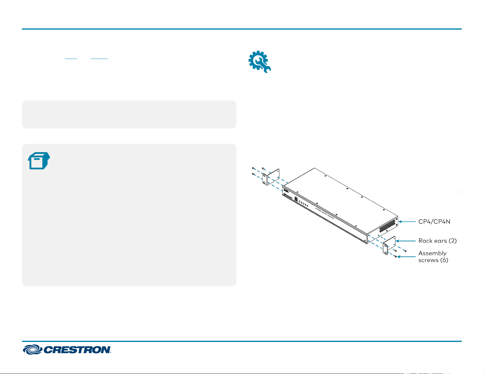
Rack Mounting
The control systemoccupies 1Uof rack space.
1. Use a #1 Phillips screwdriver to remove the six required screws from
the control system assembly (shown in the illustration below).
2. Attach the two included rack ears with the removed screws.
3. Mount the control system into the rack with four mounting screws
(not included).
Surface Placement
1. Attach the four adhesive rubber feet near the corners on the underside
of the control system.
2. Place onto a flat surface or stack with other equipment.
1
Page 2
CP4/CP4N
4-Series Control System
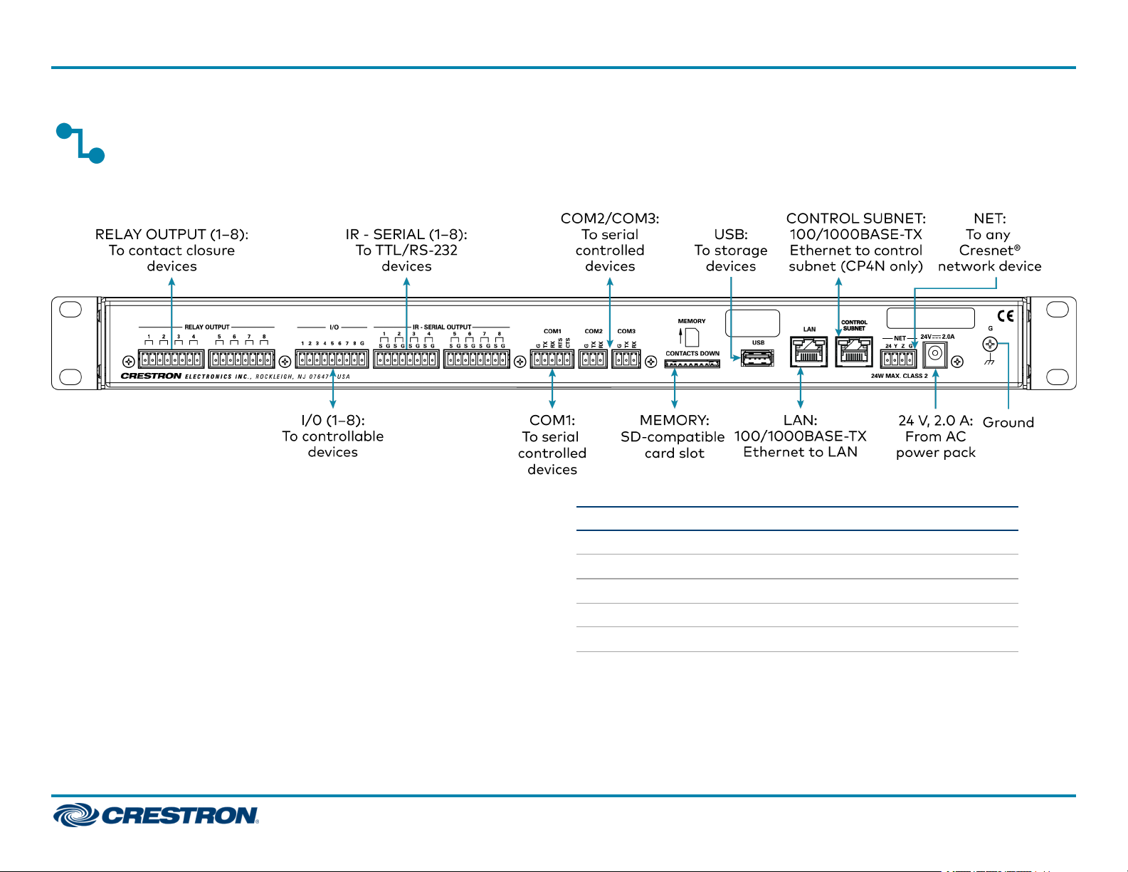
Connect the Device
Make all necessary connections to the control system as shown below.
QuickStart
Observe the following when connecting the control system:
l Use Crestron power supplies for Crestron equipment.
l The control system may be powered with the included 24 VDC power
supply or via Cresnet® network power with the NET port.
l Connect the chassis ground lug to a known earth ground circuit (such
as building steel) to ensure that the control system is grounded
properly.
l Apply power after all connections have been made.
COM1 Connections
Port RS-232 RS-422
G
GND GND GND
TX
TX(from CP4/CP4N) TX- (from CP4/CP4N) TX-/RX-
RX
RX(to CP4/CP4N) RX+(to CP4/CP4N) Not used
RTS
CTS
1. RS-422 transmit and receive are balanced signals that require two lines plus a ground
2. A ground terminal connection is recommended but not required.
RTS(from CP4/CP4N) TX+(from CP4/CP4N) TX+/RX+
CTS(to CP4/CP4N) RX- (to CP4/CP4N) Not used
in each direction. RXD+ and TXD+ should idle high (going low at start of data
transmission). RXD- and TXD- should idle low (going high at start of data
transmission). If necessary, RXD+/RXD- and TXD+/TXD- may be swapped to maintain
correct signal levels.
1
RS-485
2
2
Page 3

CP4/CP4N
4-Series Control System
QuickStart
Connect the Control Subnet
(CP4NOnly)
The CP4N has a dedicated Control Subnet that is used for
communication between the control system and Crestron Ethernet
devices without interference from other traffic on the network.
CAUTION:Do not connect the CONTROL SUBNET port to the LAN.
The CONTROL SUBNET port must only be connected to Crestron
Ethernet devices.
For more information on using the Control Subnet, refer to the 3-Series®
Control System Reference Guide (Doc. 7150) at
www.crestron.com/manuals.
Configure the Device
The control system may be configured using the provided web
configuration interface. The interface can be accessed using the control
system IP address or the Crestron XiOCloud™ service.
Configuration via IP Address
To access the web configuration interface using the control system
IPaddress:
NOTE:The control system ships with DHCPenabled. A DHCPserver is
required to access the web configuration interface via the device
IPaddress.
Configuration via Crestron XiOCloud
The Crestron XiO Cloud service allows supported Crestron devices across
an enterprise to be managed and configured from one central and secure
location in the cloud. Supported devices are configured to connect to the
service. Use of the service requires a registered Crestron XiO Cloud
account.
NOTE: The device may be disconnected from the service by navigating
to the Cloud Services tab in Crestron Toolbox software (Functions >
Device Info > Cloud Services). For details, refer to the Crestron
Toolbox help file.
To access the web configuration interface using the Crestron XiOCloud
service:
1. Connect the control system to the network.
2. Record the MAC address and serial number that are labeled on the top
of the control system. The MACaddress and serial number are
required to add the device to the service.
3. Do either of the following
l For existing accounts, access the Crestron XiO Cloud service at
https://portal.crestron.io.
l For new accounts, register for a Crestron XiO Cloud account at
www.crestron.com/xio-cloud-registration.
4. Claim the device to the service as described in the Crestron XiO Cloud
User Guide (Doc. 8214) at www.crestron.com/manuals.
5. Select the device from the cloud interface to view its settings.
1. Connect the control system to the network.
2. Use the Device Discovery tool in Crestron Toolbox™ software to
discover the control system and its IP address on the network.
3. Enter the control system IPaddress into a web browser.
3
Page 4

CP4/CP4N
4-Series Control System
QuickStart
Create an Admin Account
The first time the web configuration interface is accessed, a dialog box is
displayed asking the user to create an admin account. A similar message
is displayed when connecting to the device in Crestron Toolbox software if
an admin account has not already been created.
To create an admin account:
1. Enter a username and password for the admin account in the
appropriate text fields.
CAUTION:Do not lose the username and password for the admin
account, as the device must be reset to factory settings to regain
access.
2. Click OK. A dialog box is displayed stating that enabling authentication
will restart the web session.
3. Click Yes to confirm and restart. The username and password created
in step 1 must be entered to regain access to the web configuration
interface.
NOTE:The username and password must also be entered when
connecting from CrestronToolbox or XPanel.
Set the Time Zone
The time zone must be set on the control system to ensure that the
correct time settings are pushed to controlled devices.
To set the time zone:
1. Access the web configuration interface using either the device
IPaddress or the Crestron XiOCloud service.
2. Navigate to Settings >System Setup.
3. Select the time zone where the control system is used from the Time
Zone drop-down menu.
4. Click Save Changes on the top right of the screen.
Pair with Apple HomeKit
The control system can be paired with Apple® HomeKit® technology to
enable communication between the control system and Apple HomeKit
devices and accessories.
For pairing instructions and to locate the unique QRcode required for
pairing, refer to the CP4/CP4NProduct Information document
(Doc.8536)that shipped with the control system.
4
Page 5

CP4/CP4N
4-Series Control System
QuickStart
Additional Information
Visit the Product Page
Scan the QR code to visit the product page.
CP4
www.crestron.com/model/6510420
CP4N
www.crestron.com/model/6510419
Original Instructions
The U.S. English version of this document is the original instructions.
All other languages are a translation of the original instructions.
Crestron product development software is licensed to Crestron dealers and Crestron
Service Providers (CSPs) under a limited nonexclusive, nontransferable Software
Development Tools License Agreement. Crestron product operating system software is
licensed to Crestron dealers, CSPs, and end-users under a separate End-User License
Agreement. Both of these Agreements can be found on the Crestron website at
www.crestron.com/legal/software_license_agreement.
The product warranty can be found at www.crestron.com/warranty.
The specific patents that cover Crestron products are listed at
www.crestron.com/legal/patents.
Certain Crestron products contain open source software. For specific information, visit
www.crestron.com/opensource.
Crestron, the Crestron logo, 3-Series, Cresnet, Crestron Toolbox, and Crestron
XiOCloud are either trademarks or registered trademarks of Crestron Electronics, Inc.
in the United States and/or other countries. Apple and HomeKit are either trademarks
or registered trademarks of Apple, Inc. in the United States and/or other countries.
Other trademarks, registered trademarks, and trade names may be used in this
document to refer to either the entities claiming the marks and names or their
products. Crestron disclaims any proprietary interest in the marks and names of
others. Crestron is not responsible for errors in typography or photography.
©2020 Crestron Electronics, Inc.
Doc. 8507A
(2054285)
04/06/20
5
 Loading...