

Page 1
CRESTRON
CNXIRP
Cresnet Infrared Emitter
DESCRIPTION
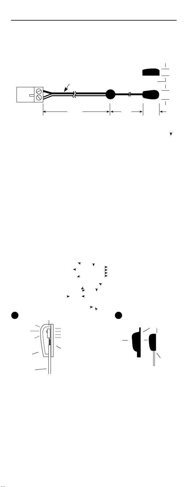
The CNXIRP, shown below, contains an infrared (IR) LED housed in a miniature,
mouse shaped, black, injection molded plastic shell. The CNXIRP shell emits
IR control signals sent to it by a Crestron control system. The shell can be
installed directly on the IR sensor window of the controlled device or at a
nearby suitable location.
2-pin
connector
NOTE: White striped
side is positive (+)
7 FT 3 FT 9/16”
Side View
1/4”
Top View
5/16”
CONTENTS
This package contains a number of ancillary parts in addition to the CNXIRP.
These parts include:
IR Mask.
Two-Sided Tape.
If after reviewing these instructions you still have additional questions, please
contact a Crestron technical support representative in your area by dialing
one of the following numbers:
* In the US and Canada, call Crestron's corporate headquarters at
1-888-CRESTRON [1-888-273-7876] or 1-201-767-3400.
* In Europe, call Crestron International at +32-15-50-99-50.
* In Asia, call Crestron Asia at +852-2341-2016.
* In Latin America, call Crestron Latin America at +525-574-15-90.
For local support from exclusive Crestron factory-trained personnel call:
* In Australia, call Soundcorp at +613-941-61066.
* In New Zealand, call Amber Technologies at +649-410-8382.
INSTALLATION
ATTACHING THE CNXIRP TO IR SENSOR WINDOWS (See A below)
1. Identify the clear adhesive layer on the flat bottom surface of the
CNXIRP shell.
2. Peel off the protective cover and affix the CNXIRP to the center of the
IR sensor window on the controlled component's front panel.
3. In some cases it may be difficult to find the location of the IR sensor on
the component. Consult the owner's manual of the unit, or the manufacturer ,
for the exact IR window location.
4. If the CNXIRP shell must be removed and repositioned for any reason,
it may be necessary to replace the adhesive with a new piece of the twosided tape (supplied) to restore adhesion.
A
High
Output
Side
CNXIRP
Shell
Mini-wire
lead
Internal
IR Emitter
Low
Output
Side
Clear adhesive layer.
(Replace, if necessary,
with a short piece of the
two-sided tape supplied).
B
IR
Mask
Side View
Adhesive Layer
CNXIRP
Shell
INSTALLING THE IR MASK (See B above)
The IR mask (supplied) is designed to fit over the CNXIRP shell, (shown
in B above), so that the sensor window of the controlled component is
completely covered. It prevents unwanted external IR signals from
passing through or leaking past it. It also prevents emitting IR from the
CNXIRP shell from radiating backward into the IR sensors of other nearby
components.
1. Without removing the adhesive backing from the CNXIRP shell or IR
mask, fit the two pieces together and accurately position them over the
IR sensor window of the component to be controlled.
2. If necessary, neatly trim the IR mask being sure that it overlaps the
extremities of the component's IR sensor window.
3. Remove the adhesive backing from the CNXIRP shell and IR mask and
position them over the IR sensor window while pressing down firmly.
Page 2

Installation Instructions
Cresnet Infrared Emitter
Crestron CNXIRP
CRESTRON CNXIRP
Cresnet Infrared Emitter
ATTACHING THE CNXIRP TO OTHER LOCATIONS
Rather than affixing the low output side of the CNXIRP shell directly over the
IR sensor window, the shell can be positioned as much as three feet away
on the axis of the IR sensor window. The high output side of the CNXIRP
shell permits control at this greater distance. Placement of the CNXIRP on
surfaces just above or below the IR sensor window, as shown below, may
provide a more pleasing aesthetic appearance. However, be sure to position
the CNXIRP shell so that the edge of the component does not block the IR
signal. Also placing the CNXIRP shell on a cabinet door may result in interruption
of the IR signal if the door is opened.
Shelves
Possible locations of CNXIRP shell attached to shelf directly below
or above IR sensor window
CONNECTING THE CNXIRP
Insert the 2-pin connector of the CNXIRP into an infrared/serial/RS-232 port
of the CNX control system, shown below. Note that the white-traced wire
connects to the pin labeled S.
A B C D E F
GS GS GS GS GS GS
IR Sensor
Window
VCR
INFRARED SERIAL RS 232S5
Crestron Electronics, Inc.
15 Volvo Drive Rockleigh, NJ 07647
Tel: 888.CRESTRON / 201.767.3400
www.crestron.com
Specifications subject to
change without notice.
Doc. 8141
09.99
 Loading...