

Page 1

Crestron CEN-RGBHV
Wideband RGB Matrix Switcher
Operations Guide
Page 2
Important Safety Instructions
This document was prepared and written by the Technical Documentation department at:
Crestron Electronics, Inc.
15 Volvo Drive
Rockleigh, NJ 07647
1-888-CRESTRON
• Read these instructions.
• Keep these instructions.
• Heed all warnings.
• Follow all instructions.
• Do not use this apparatus near water.
• Clean only with dry cloth.
• Do not block any ventilation openings. Install in accordance
with the manufacturer’s instructions.
• Do not install near any heat sources such as radiators, heat
registers, stoves, or other apparatus (including amplifiers) that
produce heat.
• Do not defeat the safety purpose of the polarized or groundingtype plug. A polarized plug has two blades with one wider than
the other. A grounding-type plug has two blades and a third
grounding prong. The wide blade or the third prong are
provided for your safety. If the provided plug does not fit into
your outlet, consult an electrician for replacement of the
obsolete outlet.
• Protect the power cord from being walked on or pinched
particularly at plugs, convenience receptacles, and the point
where they exit from the apparatus.
• Only use attachments/accessories specified by the
manufacturer.
• Unplug this apparatus during lightning storms or when unused
for long periods of time.
• Refer all servicing to qualified service personnel. Servicing is
required when the apparatus has been damaged in any way,
such as power-supply cord or plug is damaged, liquid has been
spilled or objects have fallen into the apparatus, the apparatus
has been exposed to rain or moisture, does not operate
normally, or has been dropped.
• Disconnect power prior to connecting or disconnecting
equipment.
WARNING:
TO REDUCE THE RISK OF FIRE OR ELECTRIC SHOCK,
DO NOT EXPOSE THIS APPARATUS TO RAIN OR
MOISTURE. THE APPARATUS SHALL NOT BE
EXPOSED TO DRIPPING OR SPLASHING. OBJECTS
FILLED WITH LIQUIDS, SUCH AS VASES, SHOULD
NOT BE PLACED ON THE APPARATUS.
WARNING:
TO PREVENT ELECTRIC SHOCK, DO NOT REMOVE
COVER. THERE ARE NO USER SERVICEABLE PARTS
INSIDE. ONLY QUALIFIED SERVICE PERSONNEL
SHOULD PERFORM SERVICE.
CAUTION
RISK OF ELECTRIC SHOCK
DO NOT OPEN
AVIS: RISQUE DE CHOC ELECTRIQUE NE PAS OUVRIR
The lightning flash with arrowhead symbol, within an
equilateral triangle, is intended to alert the user to the
presence of uninsulated “dangerous voltage” within the
product’s enclosure that may be of sufficient magnitude to
constitute a risk of electric shock to persons.
The exclamation point within an equilateral triangle is
intended to alert the user to the presence of important
operating and maintenance (servicing) instructions in the
literature accompanying the appliance.
WARNING:
THIS IS AN APPARATUS WITH CLASS I
CONSTRUCTION. IT SHALL BE CONNECTED TO AN
ELECTRICAL OUTLET WITH AN EARTHING GROUND
TERMINAL.
• Do not install in direct sunlight.
• The apparatus must be installed in a way that the power cord
can be removed either from the wall outlet or from the device
itself in order to disconnect the mains power.
• Prevent foreign objects from entering the device.
IMPORTANT:
The CEN-RGBHV can be used with Class 2 output wiring.
All brand names, product names and trademarks are the property of their respective owners.
©2007 Crestron Electronics, Inc.
Page 3

Crestron CEN-RGBHV Wideband RGB Matrix Switcher
Contents
Wideband RGB Matrix Switcher: CEN-RGBHV 1
Introduction ...............................................................................................................................1
Features and Functions................................................................................................ 1
Specifications ..............................................................................................................3
Physical Description.................................................................................................... 5
Industry Compliance .................................................................................................16
Setup ........................................................................................................................................ 17
Network Wiring......................................................................................................... 17
Ethernet .....................................................................................................................17
Identity Code ............................................................................................................. 17
Installation................................................................................................................. 18
Hardware Hookup .....................................................................................................20
Programming Software............................................................................................................22
Earliest Version Software Requirements for the PC .................................................22
Programming with Crestron SystemBuilder.............................................................. 22
Programming with SIMPL Windows........................................................................ 23
Example Program...................................................................................................... 25
Uploading and Upgrading........................................................................................................ 26
Establishing Communication.....................................................................................26
Programs and Firmware ............................................................................................27
Program Checks ........................................................................................................27
Operation .................................................................................................................................29
Menu Structure .......................................................................................................... 29
Setup and Informational Screens............................................................................... 29
Routing Signals .........................................................................................................46
Sync Mode................................................................................................................. 47
Problem Solving ......................................................................................................................48
Troubleshooting......................................................................................................... 48
Check Network Wiring..............................................................................................48
Reference Documents................................................................................................48
Further Inquiries........................................................................................................49
Future Updates ..........................................................................................................49
Return and Warranty Policies.................................................................................................. 50
Merchandise Returns / Repair Service ......................................................................50
CRESTRON Limited Warranty.................................................................................50
Operations Guide – DOC. 6612A Contents • i
Page 4

Page 5

Crestron CEN-RGBHV Wideband RGB Matrix Switcher
Wideband RGB Matrix Switcher:
Wideband RGB Matrix Switcher: CEN-RGBHV
CEN-RGBHV
Introduction Introduction
Crestron wideband matrix switchers are designed to provide flexible signal routing
of high-res video and audio for the most demanding presentation environments. With
extremely low crosstalk, 450 MHz video bandwidth, professional balanced audio and
full Crestron control system integration, the CEN-RGBHV8X4, CEN-RGBHV8X8,
CEN-RGBHV12X4, CENRGBHV12X8 and CEN-RGBHV16X16 (hereinafter
collectively referred to as CEN-RGBHGV), satisfy the demanding video
requirements of corporate boardrooms and training centers, university lecture halls,
high-tech houses of worship, command and control facilities and live staging events.
Features and Functions
• High bandwidth matrix switcher
8 x 4 in CEN-RGBHV8X4
8 x 8 in CEN-RGBHV8X8
12 x 4 in CEN-RGBHV12X4
12 x 8 in CEN-RGBHV12X8
16 x 16 in CEN-RGBHV16X16
• Low crosstalk with incredibly flat response
• 450 MHz video bandwidth (-3 dB)
• Professional balanced stereo audio
• Audio input level compensation
• Audio output volume and mute control
• Input sync detection and Genlock sync input
• Adjustable video and audio blanking
• Selectable input sync impedance
• Standalone operation with LCD driven front control panel
• Cresnet
• Three space rack mount installation (except CEN-RGBHV16X16
which requires six space rack mount installation)
®
or high speed Ethernet communications
Operations Guide – DOC. 6612A Wideband RGB Matrix Switcher: CEN-RGBHV • 1
Page 6

Wideband RGB Matrix Switcher Crestron CEN-RGBHV
High Bandwidth Matrix Router
The CEN-RGBHV is a high bandwidth matrix switcher capable of routing up to
eight (CEN-RGVHV8X4, CEN-RGBHV8X8), 12 (CEN-RGBHV12X4,
CEN-RGBHV12X8) or 16 (CEN-RGBHV16X16) computer or video sources to up
to four (CEN-RGBHV8X4, CEN-RGBHV12X4), eight (CEN-RGBHV8X8,
CEN-RGBHV12X8) or 16 (CEN-RGBHV16X16) display devices. Its five matrix
levels accommodate any combination of analog RGBHV, HD/component,
S-video and composite signals. Proven flat response achieves optimum performance
even at the highest bandwidth. Selectable sync impedance on every input helps
accommodate varying cable lengths.
Glitch-free Switching
Video-follow-sync switching ensures a glitch-free transition when selecting between
non-synchronous sources. Blanking time is independently adjustable per output from
0 to 10 seconds, allowing each display device time to lock to the new sync signal
before displaying the video image whenever a new source is selected. A sync
reference input is also provided to support vertical interval switching of genlocked
sources.
Sync Detection
Video sync detection on each input measures the H and V sync rates of every RGB
source and allows their values to be viewed on the front panel display, control
system touchpanel or RoomView® software.
Professional Stereo Audio Matrix
A stereo audio matrix is also included (8 x 4 on the CEN-RGBHV8X4, 8 x 8 on the
CEN-RGBHV8X8, 12 x 4 on the CEN-RGBHV12X4, 12 x 8 on the
CEN-RGBHV12X8 and 16 x 16 on the CEN-RGBHV16X16), supporting both
balanced and unbalanced signals. Programmable input level compensation helps
ensure compatibility with a wide range of pro and semi-pro sources. Automatic
blanking achieves a pop-free transition when switching between sources. Every
output includes volume and mute control, providing multiple channels of real-time
controllable audio signal distribution to feed multi-zone amplifiers, assistive
listening and recording equipment. Audio breakaway capability allows any audio
input or output to be linked with its respective video channel or switched
independently.
Full-featured Front Panel
The CEN-RGBHV is fully operable out of the box for use as a standalone switcher.
Featuring an informative LCD display and quick adjust knob, the front panel
supports essential switcher operation without requiring a computer or control system.
Advanced setup is available through Crestron Toolbox™ software. All signal routing
and audio compensation settings are stored in non-volatile memory onboard the
switcher.
Customizable label strips are provided on the front panel for clear designation of its
inputs and outputs using Crestron Engraver software or standard 3/8” tape labels.
Names may also be entered through software to appear on the LCD display during
operation. For security, the front panel controls can be password protected or locked
out.
2 • Wideband RGB Matrix Switcher: CEN-RGBHV Operations Guide – DOC. 6612A
Page 7
Crestron CEN-RGBHV Wideband RGB Matrix Switcher
Crestron System Integration
Via Cresnet® or high speed Ethernet, Crestron switchers offer the ultimate in control
system integration with every function accessible through SIMPL™ Windows® or
SystemBuilder™ without deciphering cryptic protocols. Up to 10 presets containing
numerous routes can be saved onboard the CEN-RGBHV for instant recall.
Integration with any 2-Series Control system also provides the gateway to Crestron's
RoomView
remote monitoring and control.
®
Asset Management Software and e-Control®2 Xpanel Solutions for
Specifications
Specifications for the CEN-RGBHV are listed in the following table.
CEN-RGBHV Specifications
SPECIFICATION DETAILS
Video/RGB
Switcher
Signal Types
Video/HDTV Formats
RGB Formats
Gain
Bandwidth
Blanking Time
Crosstalk
Audio
Switcher
Input Compensation
Output Volume Control
Blanking Time
Frequency Response 20 Hz to 20 kHz ±0.5 dB
Ethernet
Crosspoint matrix
CEN-RGBHV8X4: 8 x 4 (x5)
CEN-RGBHV8X8: 8 x 8 (x5)
CEN-RGBHV12X4: 12 x 4 (x5)
CEN-RGBHV12X8: 12 x 8 (x5)
CEN-RGBHV16X16: 16 x 16 (x5),
adjustable blanking, sync detection, selectable
input termination, vertical interval switching
using genlock input
RGB and composite, S-video or component
video (does not transcode)
NTSC or PAL, HDTV up to 1080i/1080p
RGBHV, RGBS, RG
0 dB (75 Ω terminated)
450 MHz (-3 dB) fully loaded
Adjustable 0 to 10 seconds, 0.5 second steps
-65 dB @ 5 MHz
-47 dB @ 100 MHz
Stereo crosspoint matrix
CEN-RGBHV8X4: 8 x 4
CEN-RGBHV8X8: 8 x 8
CEN-RGBHV12X4: 12 x 4
CEN-RGBHV12X8: 12 x 8
CEN-RGBHV16X16: 16 x 16,
input compensation, output volume and mute
control, adjustable blanking, audio breakaway
±10 dB in 0.5 dB steps
-60 dB to + 20 dB in 0.5 dB steps
Adjustable 0 to 10 seconds, 0.5 second steps
10/100 BaseT, static IP or DHCP/DNS, autonegotiating, auto discovery, full/half duplex,
TCP/IP, UDP/IP or CIP
B or YUV
s
(Continued on following page)
Operations Guide – DOC. 6612A Wideband RGB Matrix Switcher: CEN-RGBHV • 3
Page 8
Wideband RGB Matrix Switcher Crestron CEN-RGBHV
CEN-RGBHV Specifications (Continued)
SPECIFICATION DETAILS
Power Requirements
Main Power 2 Amps @ 100-240 Volts AC, 50/60 Hz
Cresnet Power Usage None
Default Net ID 33
Minimum 2-Series Control
System Update File
Environmental
Temperature 32º to 104ºF (0º to 40ºC)
Humidity 10% to 90% RH (non-condensing)
Heat Dissipation
Enclosure
Chassis
Faceplate
Mounting
Dimensions
Height (without feet)
Width (without ears)
Width (with ears) 19.00 in (48.26 cm)
Depth
Weight
1. The latest software versions can be obtained from the Crestron website. Refer to the NOTE following
these footnotes.
2. Crestron 2-Series control systems include the AV2 and PRO2. Consult the latest Crestron Product
Catalog for a complete list of 2-Series control systems.
3. 3U for CEN-RGBHV8X4, CEN-RGBHV8X8, CEN-RGBHV12X4 and CEN-RGBHV12X8; 6U for
CEN-RGBHV16X16.
1, 2
Version 3.137 or later
CEN-RGBHV8X4, CEN-RGBHV8X8,
CEN-RGBHV12X4, CEN-RGBHV12X8:
290 BTU/Hr
CEN-RGBHV16X16: 460 BTU/Hr
Steel, black matte power coat finish, vented
sides, fan cooled
Extruded aluminum, black matte powder coat
finish with polycarbonate label overlay
Freestanding or 19-inch rack mountable
(adhesive feet and rack ears included)
5.20 in (13.21 cm)
10.47 in (26.60 cm) (CEN-RGBHV16X16 only)
17.03 in (43.24 cm)
17.28 in (43.90 cm) (CEN-RGBHV16X16 only)
13.10 in (33.26 cm)
20.68 in (52.51 cm) (CEN-RGBHV16X16 only)
CEN-RGBHV8X4, CEN-RGBHV8X8,
CEN-RGBHV12X4, CEN-RGBHV12X8:
15 lbs (6.80 kg)
CEN-RGBHV16X16: 40 lbs (18.14 kg)
3
NOTE: Crestron software and any files on the website are for authorized Crestron
dealers and Crestron Authorized Independent Programmers (CAIP) only. New users
may be required to register to obtain access to certain areas of the site (including the
FTP site).
4 • Wideband RGB Matrix Switcher: CEN-RGBHV Operations Guide – DOC. 6612A
Page 9
Crestron CEN-RGBHV Wideband RGB Matrix Switcher
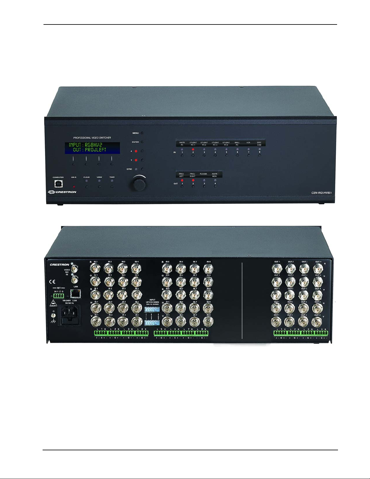
Physical Description
This section provides information on the connections, controls and indicators
available on your CEN-RGBHV.
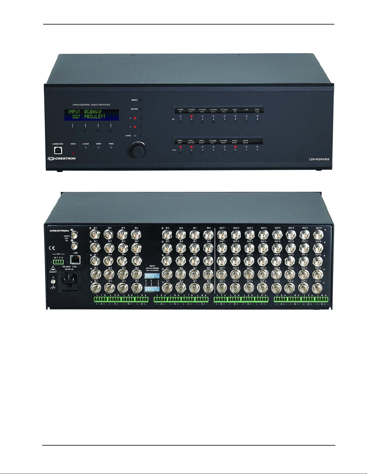
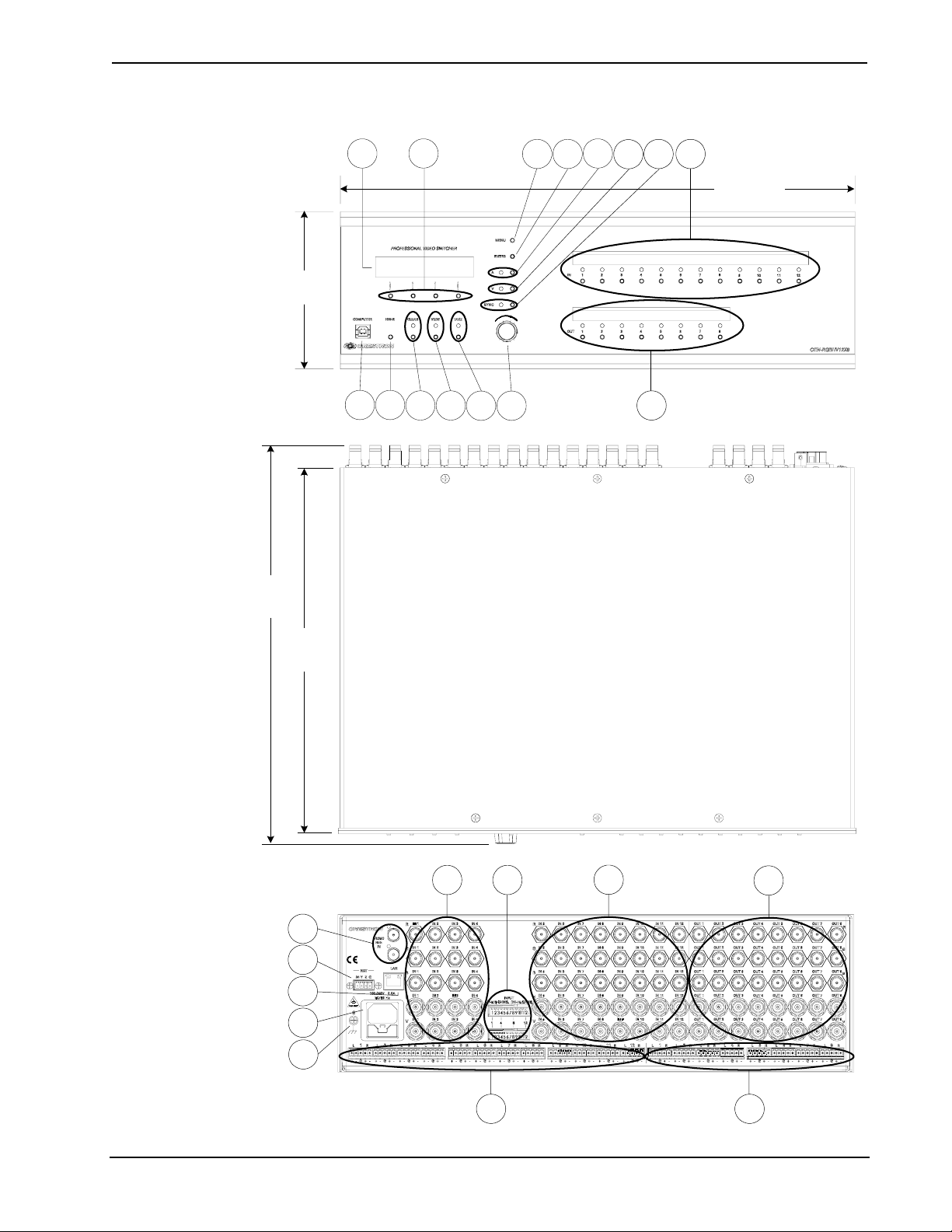
CEN-RGBHV8X4 Front View
CEN-RGBHV8X4 Rear View
Operations Guide – DOC. 6612A Wideband RGB Matrix Switcher: CEN-RGBHV • 5
Page 10
Wideband RGB Matrix Switcher Crestron CEN-RGBHV
CEN-RGBHV8X8 Front View
CEN-RGBHV8X8 Rear View
6 • Wideband RGB Matrix Switcher: CEN-RGBHV Operations Guide – DOC. 6612A
Page 11
Crestron CEN-RGBHV Wideband RGB Matrix Switcher
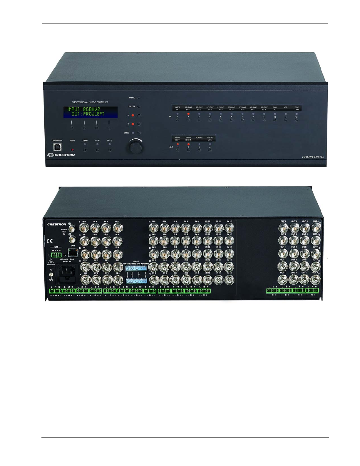
CEN-RGBHV12X4 Front View
CEN-RGBHV12X4 Rear View
Operations Guide – DOC. 6612A Wideband RGB Matrix Switcher: CEN-RGBHV • 7
Page 12

Wideband RGB Matrix Switcher Crestron CEN-RGBHV
CEN-RGBHV12X8 Front View
CEN-RGBHV12X8 Rear View
8 • Wideband RGB Matrix Switcher: CEN-RGBHV Operations Guide – DOC. 6612A
Page 13
Crestron CEN-RGBHV Wideband RGB Matrix Switcher
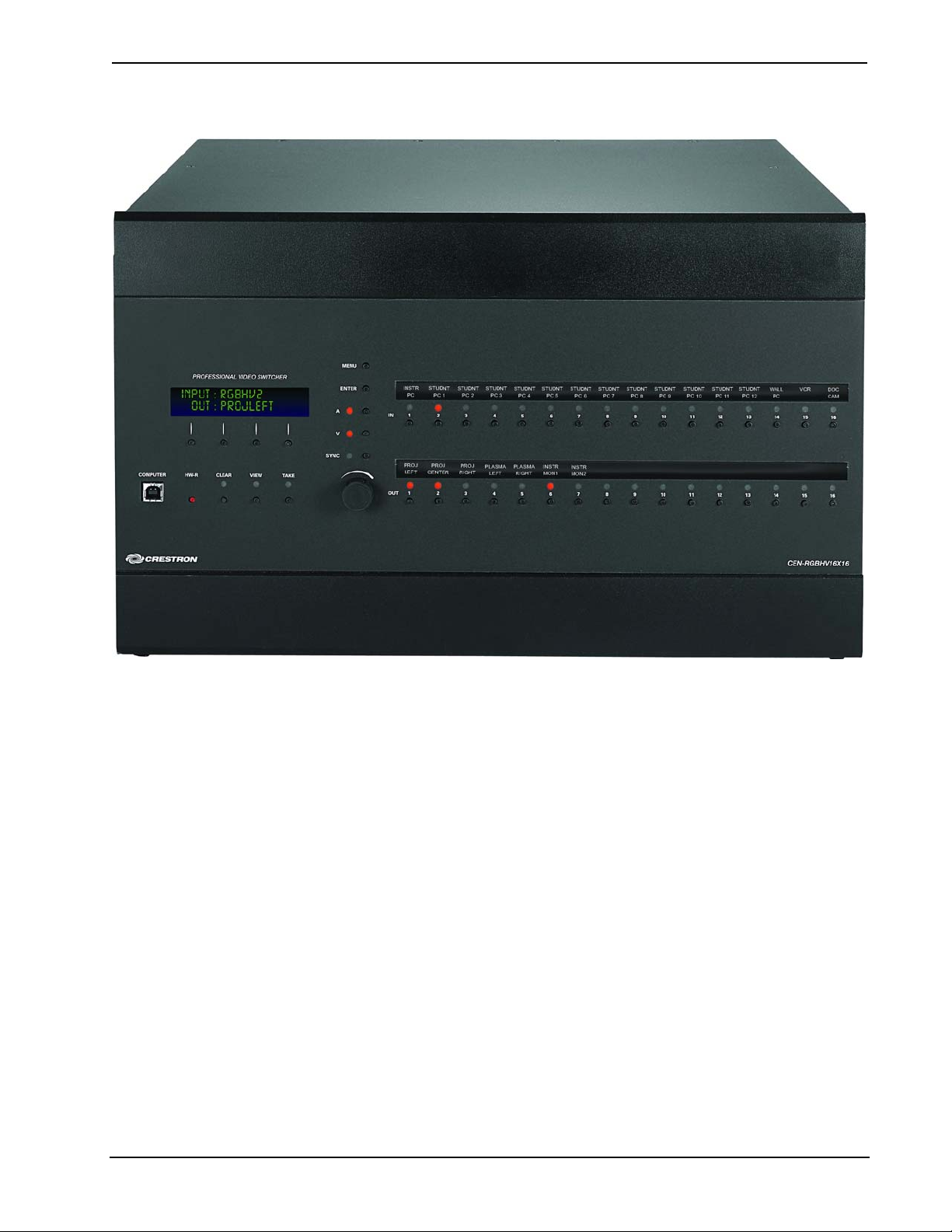
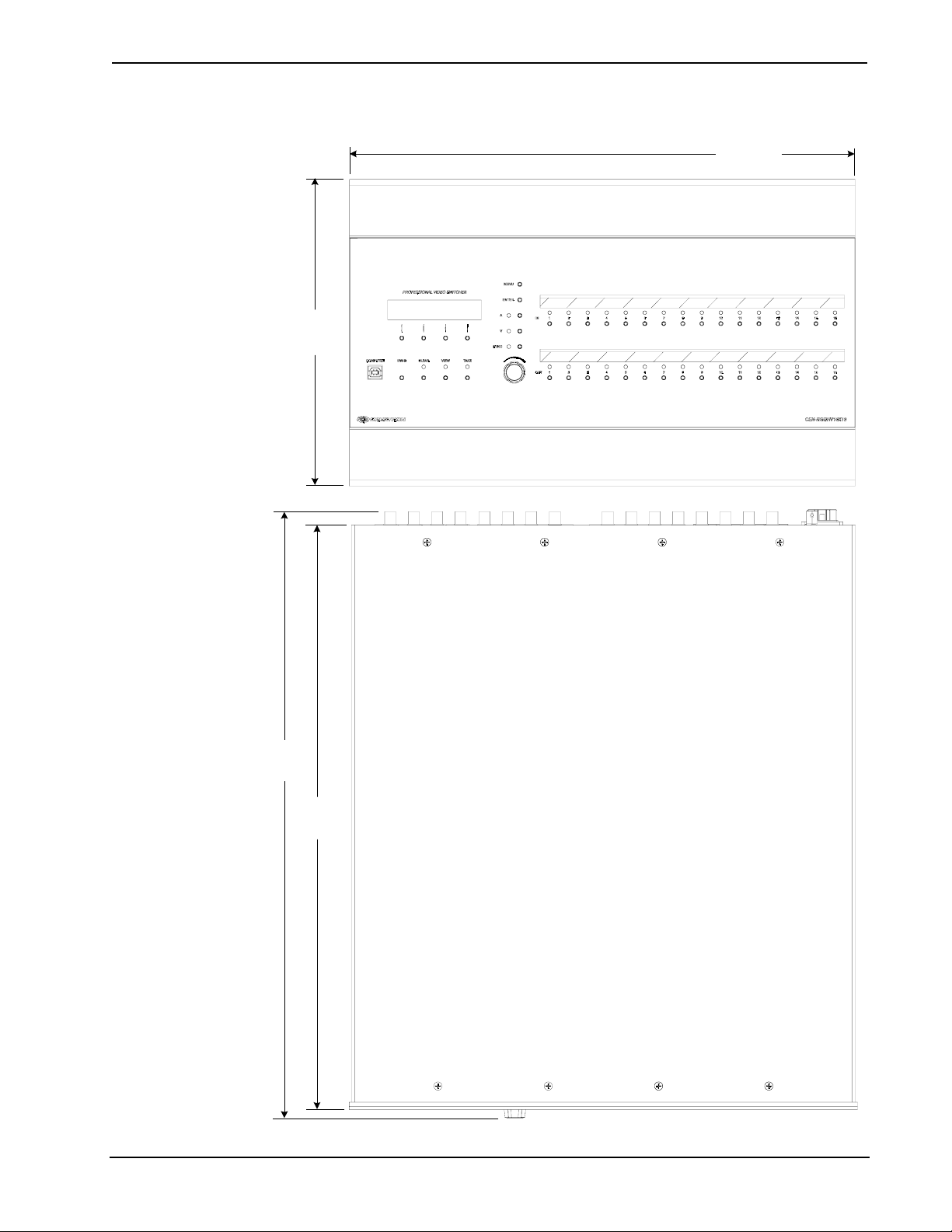
CEN-RGBHV16X16 Front View
Operations Guide – DOC. 6612A Wideband RGB Matrix Switcher: CEN-RGBHV • 9
Page 14
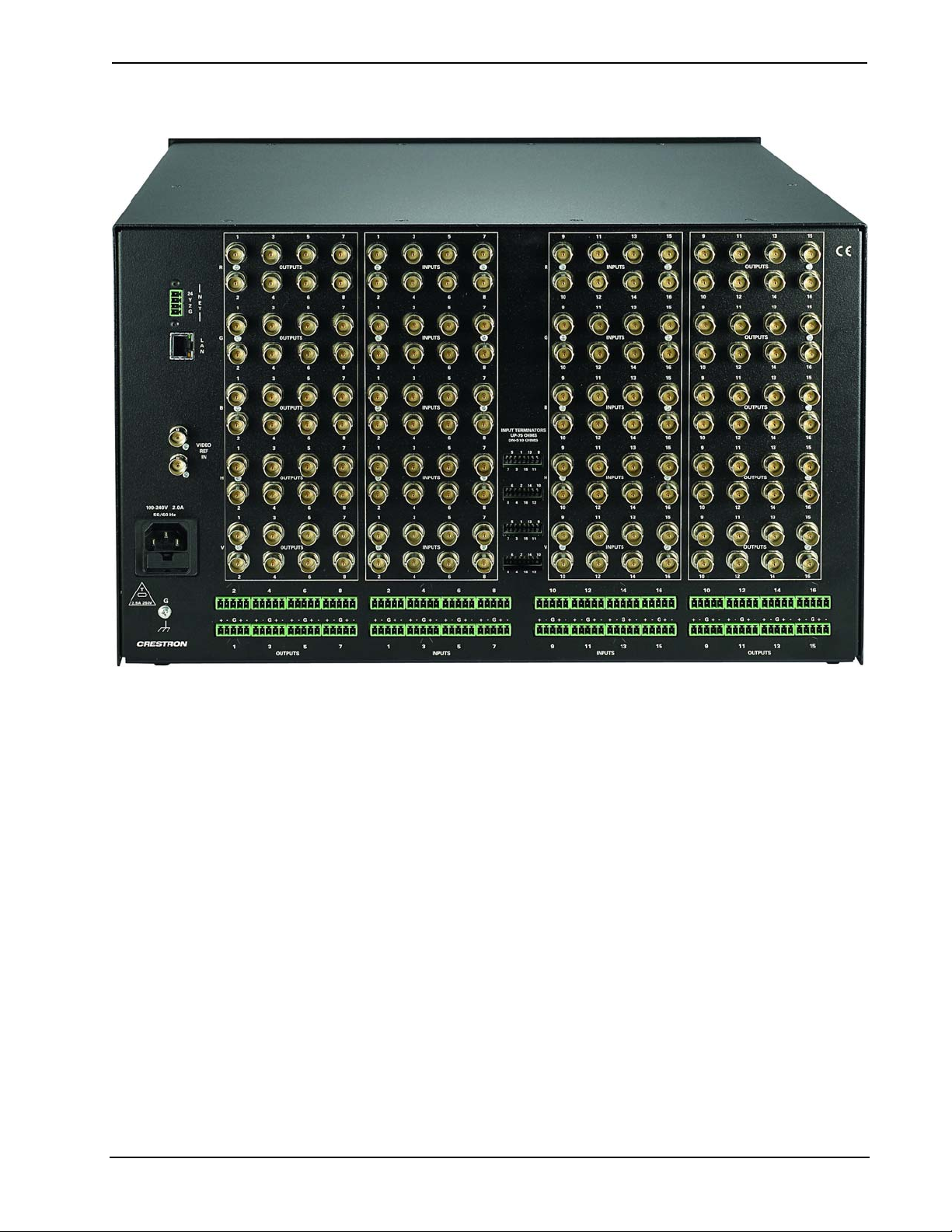
Wideband RGB Matrix Switcher Crestron CEN-RGBHV
CEN-RGBHV16X16 Rear View
10 • Wideband RGB Matrix Switcher: CEN-RGBHV Operations Guide – DOC. 6612A
Page 15
Crestron CEN-RGBHV Wideband RGB Matrix Switcher
CEN-RGBHV8X4, CEN-RGBHV8X8, CEN-RGBHV12X4, CEN-RGBHV12X8 Overall Dimensions (CEN-RGBHV12X8 Shown)
5.20 in
(13.21 cm)
13.10 in
(33.26 cm)
1 2 3
9 10 11
12
13
14 15
5 6
4
8
7
17.03 in
(43.24 cm)
12.03 in
(30.55 cm)
19
20
21
22
23
16
17 18
16
24 25
Operations Guide – DOC. 6612A Wideband RGB Matrix Switcher: CEN-RGBHV • 11
Page 16
Wideband RGB Matrix Switcher Crestron CEN-RGBHV
CEN-RGBHV16X16 Overall Dimensions
17.28 in
(43.90 cm)
10.47 in
(26.60 cm)
20.68 in
(52.51 cm)
19.86 in
(50.45 cm)
12 • Wideband RGB Matrix Switcher: CEN-RGBHV Operations Guide – DOC. 6612A
Page 17
Crestron CEN-RGBHV Wideband RGB Matrix Switcher
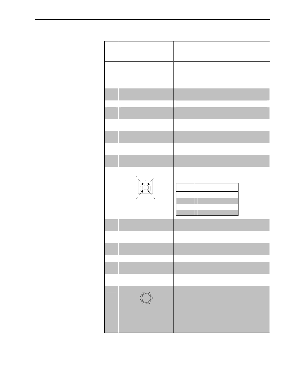
Connectors, Controls & Indicators
#
CONNECTORS
CONTROLS &
INDICATORS
1
,
DESCRIPTION
1 LCD DISPLAY
Green LCD alphanumeric, adjustable
backlight; 2 lines x 20 characters per line;
displays inputs/outputs by name, scan rates,
audio levels, setup menus and other
information.
2 SOFTKEYS
(4) pushbuttons for activation of LCD driven
functions and pass code entry.
3 MENU (1) pushbutton, steps menu back one level.
4 ENTER
(1) pushbutton, executes highlighted menu or
value.
5 A
(1) pushbutton & red LED, selects audio
routing view.
6 V
(1) pushbutton & red LED, selects video
routing view.
7 SYNC
(1) pushbutton & red LED, displays input
sync rates.
8 IN
(8, 12 or 16)2 pushbuttons & red LEDs,
select input to be routed.
9
COMPUTER
Pin 2 Pin 1
USB
(1) USB Type B female; USB 1.1 computer
console port (6 foot cable included).
PIN DESCRIPTION
Pin 3 Pin 4
1 +5 VDC
2 Data -
3 Data +
4 Ground
10 HW-R
(1) recessed miniature pushbutton for
hardware reset, reboots the switcher.
11 CLEAR
(1) pushbutton & red LED, clears all matrix
routing.
12 VIEW
(1) pushbutton & red LED, toggles VIEW
mode on/off.
13 TAKE (1) pushbutton & red LED, executes routing.
14 QUICK-ADJUST KNOB
(1) continuous turn rotary encoder, adjusts
menu parameters.
15 OUT
(4, 8 or 16)
3
pushbuttons & red LEDs, select
output destination.
16
(VIDEO) IN
(8, 12 or 16)2 sets of (5) BNC female, each
set comprising (3) high bandwidth video
inputs plus (2) sync inputs;
Input level: 0.2 to 5.0 V
p-p
;
RGB input impedance: 75 Ω nominal; Sync
input impedance: 75 or 510 Ω, independently
selectable for H and V per input;
Return loss: < -30 dB @ 5 MHz;
Sync detection on every input connector.
(Continued on following page)
Operations Guide – DOC. 6612A Wideband RGB Matrix Switcher: CEN-RGBHV • 13
Page 18

Wideband RGB Matrix Switcher Crestron CEN-RGBHV
Connectors, Controls & Indicators (Continued)
#
CONNECTORS
CONTROLS &
INDICATORS
1
,
DESCRIPTION
INPUT TERMINATORS
17
(
CEN-RGBHV8X4 &
CEN-RGBHV8X8)
CEN-RGBHV12X4 &
(
CEN-RGBHV12X8)
CEN-RGBHV16X16)
(
(16, 24 or 32)4 DIP switches, select input
termination for each input, independently for
H and V sync.
18
(VIDEO) OUT
(4, 8 or 16)3 sets of (5) BNC female, each set
comprising (3) high bandwidth video inputs
plus (2) sync inputs;
Output level: 0.2 to 5.0 V
p-p
;
Output impedance: 75 Ω nominal;
Return loss: < -30 dB @ 5 MHz
(Continued on following page)
14 • Wideband RGB Matrix Switcher: CEN-RGBHV Operations Guide – DOC. 6612A
Page 19

Crestron CEN-RGBHV Wideband RGB Matrix Switcher
Connectors, Controls & Indicators (Continued)
#
CONNECTORS
CONTROLS &
INDICATORS
1
,
DESCRIPTION
19
20
21
22
VIDEO REF IN
NET
24 Y Z G
5
LAN
GREEN
LED
PIN 8
YELLOW
LED
PIN 1
100-240V~2.0A
50/60Hz
(2) BNC female; Genlock sync reference
input and loop thru, unterminated.
(1) 4-pin 3.5 mm detachable terminal block;
Cresnet slave port, connects to Cresnet
control network;
Does not draw power from the network.
(1) 8-wire RJ-45 with two LED indicators;
10BaseT/100BaseTX Ethernet port;
Green LED indicates link status;
Yellow LED indicates Ethernet activity.
PIN SIGNAL PIN SIGNAL
1 TX + 5 N/C
2 TX - 6 RC 3 RC+ 7 N/C
4 N/C 8 N/C
(1) IEC socket, main power input;
Mates with removable power cord (included)
Dual fuse holder requires (1) 20 mm x 5 mm
time lag type fuse rated for 2.5 Amps / 250
Volts and (1) 20 mm x 5 mm time lag type
fuse rated for 10 Amps / 250 Volts6.
23
G
(1) 6-32 screw, chassis ground lug.
24
(AUDIO) IN
(8, 12 or 16)2 5-pin 3.5 mm detachable
terminal blocks;
Balanced/unbalanced stereo line level inputs;
6 V
rms
unbalanced;
Maximum input level: 12 V
balanced,
rms
Input impedance: 20 kΩ balanced,
10 kΩ unbalanced.
25
(AUDIO) OUT
(4, 8 or 16)
3
5-pin 3.5 mm detachable
terminal blocks;
Balanced/unbalanced stereo line level
outputs;
Maximum output level: 12 V
unbalanced;
6 V
rms
balanced,
rms
Output impedance: 100 Ω balanced,
50 Ω unbalanced.
1. An interface connector for the NET port is provided with the unit.
Operations Guide – DOC. 6612A Wideband RGB Matrix Switcher: CEN-RGBHV • 15
Page 20

Wideband RGB Matrix Switcher Crestron CEN-RGBHV
2. 1 – 8 on CEN-RGBHV8X4 and CEN-RGBHV8X8; 1 – 12 on CEN-RGBHV12X4 and
CEN-RGBHV12X8; 1 – 16 on CEN-RGBHV16X16.
3. 1 – 4 on CEN-RGBHV8X4 and CEN-RGBHV12X4; 1 – 8 on CEN-RGBHV8X8 and
CEN-RGBHV12X8; 1 – 16 on CEN-RGBHV16X16.
4. 16 on CEN-RGBHV8X4 and CEN-RGBHV8X8; 24 on CEN-RGBHV12X4 and
CEN-RGBHV12X8; 32 on CEN-RGBHV16X16.
5. To determine which is pin 1 on the cable, hold the cable so that the end of the eight pin modular jack
is facing away from you, with the clip down and copper side up. Pin 1 is on the far left.
6. Refer to “Fuse Replacement” on page 20 for additional details.
Industry Compliance
As of the date of manufacture, the CEN-RGBHV has been tested and found to
comply with specifications for CE marking and standards per EMC and
Radiocommunications Compliance Labelling.
NOTE: This device complies with part 15 of the FCC rules. Operation is subject to
the following two conditions: (1) this device may not cause harmful interference and
(2) this device must accept any interference received, including interference that may
cause undesired operation.
This equipment has been tested and found to comply with the limits for a Class B
digital device, pursuant to part 15 of the FCC Rules. These limits are designed to
provide reasonable protection against harmful interference in a residential
installation. This equipment generates, uses and can radiate radio frequency energy
and if not installed and used in accordance with the instructions, may cause harmful
interference to radio communications. However, there is no guarantee that
interference will not occur in a particular installation. If this equipment does cause
harmful interference to radio or television reception, which can be determined by
turning the equipment off and on, the user is encouraged to try to correct the
interference by one or more of the following measures:
Reorient or relocate the receiving antenna.
Increase the separation between the equipment and receiver.
Connect the equipment into an outlet on a circuit different from that to
which the receiver is connected.
Consult the dealer or an experienced radio/TV technician for help.
16 • Wideband RGB Matrix Switcher: CEN-RGBHV Operations Guide – DOC. 6612A
Page 21

Crestron CEN-RGBHV Wideband RGB Matrix Switcher
Setup
Network Wiring
When wiring the network, consider the following:
• Use Crestron Certified Wire.
• Provide sufficient power to the system.
• For larger networks, use a Cresnet Hub/Repeater (CNXHUB) to maintain
signal quality.
For more details, refer to “Check Network Wiring” on page 48.
Ethernet
The CEN-RGBHV also uses high-speed Ethernet for communications between the
device and a control system or computer.
Net ID
IP ID
For information on connecting Ethernet devices in a Crestron system, refer to the
latest version of the Crestron e-Control
available for download from the Crestron website (www.crestron.com/manuals
Reference Guide (Doc. 6052), which is
).
Identity Code
The Net ID of the CEN-RGBHV has been factory set to 33. The Net IDs of multiple
CEN-RGBHV devices in the same system must be unique. Net IDs are changed from
a personal computer (PC) via the Crestron Toolbox (refer to “Establishing
Communication” on page 26).
When setting the Net ID, consider the following:
• The Net ID of each unit must match an ID code specified in the SIMPL
Windows program.
• Each network device must have a unique Net ID.
For more details, refer to the Crestron Toolbox help file.
The IP ID is set within the CEN-RGBHV’s table using Crestron Toolbox. For
information on setting an IP table, refer to the Crestron Toolbox help file. The IP IDs
of multiple CEN-RGBHV devices in the same system must be unique.
When setting the IP ID, consider the following:
• The IP ID of each unit must match an IP ID specified in the SIMPL
Windows program.
• Each device using IP to communicate with a control system must have a
unique IP ID.
Operations Guide – DOC. 6612A Wideband RGB Matrix Switcher: CEN-RGBHV • 17
Page 22

Wideband RGB Matrix Switcher Crestron CEN-RGBHV
Installation
Ventilation
Rack Mounting
The CEN-RGBHV should be used in a well-ventilated area. The venting holes
should not be obstructed under any circumstances.
To prevent overheating, do not operate this product in an area that exceeds the
environmental temperature range listed in the table of specifications. Consider using
forced air ventilation and/or incrementing the spacing between units to reduce
overheating. Consideration must be given if installed in a closed or multi-unit rack
assembly since the operating ambient temperature of the rack environment may be
greater than the room ambient temperature. Contact with thermal insulating materials
should be avoided on all sides of the unit.
The CEN-RGBHV can be mounted in a rack or stacked with other equipment. Two
“ears” and an appropriate number of longer screws are provided with the
CEN-RGBHV so that the unit can be rack mounted. These ears must be installed
prior to mounting. Complete the following procedure to attach the ears to the unit.
The only tool required is a #2 Phillips screwdriver.
WARNING: To prevent bodily injury when mounting or servicing this unit in a
rack, take special precautions to ensure that the system remains stable. The following
guidelines are provided to ensure your safety:
• When mounting this unit in a partially filled rack, load the rack from the
bottom to the top with the heaviest component at the bottom of the rack.
• If the rack is provided with stabilizing devices, install the stabilizers before
mounting or servicing the unit in the rack.
NOTE: If rack mounting is not required, rubber feet are provided for tabletop
mounting or stacking. Apply the feet near the corner edges on the underside of the
unit.
NOTE: Reliable earthing of rack-mounted equipment should be maintained.
Particular attention should be given to supply connections other than direct
connections to the branch circuit (e.g. use of power strips).
To install the ears:
1. There are screws that secure each side of the CEN-RGBHV top cover.
Using a #2 Phillips screwdriver, remove the three screws (six screws on the
CEN-RGBHV16X16) closest to the front panel from one side of the unit.
Refer to the diagram following step 3 for a detailed view.
2. Position a rack ear so that its mounting holes align with the holes vacated
by the screws in step 1.
3. Secure the ear to the unit using the longer #6-32 screws that came packed
separately with your unit, as shown in the diagram on the following page.
18 • Wideband RGB Matrix Switcher: CEN-RGBHV Operations Guide – DOC. 6612A
Page 23

Crestron CEN-RGBHV Wideband RGB Matrix Switcher
Ear Attachment for Rack Mounting (this image shows a CEN-RGBHV12X8)
USE LONGER
SCREWS THAT SHIP
WITH THE UNIT
4. Repeat procedure (steps 1 through 3) to attach the remaining ear to the
opposite side.
Stacking
Four “feet” are provided with the CEN-RGBHV so that if the unit is not rack
mounted, the rubber feet can provide stability when the unit is placed on a flat
surface or stacked. These feet should be attached prior to the hookup procedure.
Refer to the following illustration for placement of the feet.
Foot Placement for the CEN-RGBHV
PLACE FEET IN CORNERS
Operations Guide – DOC. 6612A Wideband RGB Matrix Switcher: CEN-RGBHV • 19
Page 24

Wideband RGB Matrix Switcher Crestron CEN-RGBHV
Hardware Hookup
Connect the Device
Make the necessary connections as called out in the illustration that follows this
paragraph. Refer to “Network Wiring” on page 17 before attaching the 4-position
terminal block connector. Apply power after all connections have been made.
Hardware Connections for the CEN-RGBHV (CEN-RGBHV12X8 Shown)
COMPUTER:
TO PC
(VIDEO) IN:
VIDEO REF IN:
FROM SYNC REFERENCE
LAN:
10/100 BASE-T
ETHERNET TO LAN
CRESNET:
TO CONTROL SYSTEM AND
OTHER CRESNET DEVICES
GROUND
100-240V ~2.0A
50/60 HZ:
MAIN POWER INPUT
FROM RGBHV OUTPUTS
(AUDIO) IN:
FROM BALANCED/
UNBALANCED STEREO
LINE LEVEL OUTPUTS
(VIDEO) OUT:
TO RGBHV INPUTS
(AUDIO) OUT:
TO BALANCED/
UNBALANCED STEREO
LINE LEVEL INPUTS
NOTE: Ensure the unit is properly grounded.
Fuse Replacement
If the CEN-RGBHV does not power up when it is plugged into an AC outlet, one or
both fuses may need to be replaced. The fuse holder is located on the rear panel, as
the lower section of the IEC socket assembly. To replace one or both fuses:
1. Disconnect power to the CEN-RGBHV.
2. To release the fuse holder, grip the fuse holder top and bottom, while
pressing down on the tab in the center of the top.
3. Remove the defective fuse(s) from the fuse holder and replace with one or
two new ones as needed.
CAUTION: Use only time lag type fuses, 2.5 Amps / 250 Volts for the line
(“hot”) leg and 10 Amps / 250 Volts for neutral leg. Failure to do so may cause
damage to the CEN-RGBHV.
20 • Wideband RGB Matrix Switcher: CEN-RGBHV Operations Guide – DOC. 6612A
Page 25

Crestron CEN-RGBHV Wideband RGB Matrix Switcher
CAUTION: To prevent possible equipment damage, it is important to use the
correct value fuse in the correct position in the fuse holder. As you face the rear
of the CEN-RGBHV, the line (“hot”) fuse will be on the left side of the fuse
holder. This fuse should have a value of 2.5 Amps / 250 Volts. The neutral fuse
will be on the right side of the fuse holder and should have a value of 10 Amps /
250 Volts.
4. Inert the fuse holder in the CEN-RGBHV and push it inward until it clicks
into place.
5. Connect power to the CEN-RGBHV.
Label the Buttons
Use Crestron Engraver software to print custom labels for the CEN-RGBHV’s front
panel buttons and LEDS. Crestron recommends printing on 100-pound paper. Paper
weighing less than 100 pounds will tend to crumple while sliding in, while paper
weighing more than 100 pounds may not fit.
Operations Guide – DOC. 6612A Wideband RGB Matrix Switcher: CEN-RGBHV • 21
Page 26
Wideband RGB Matrix Switcher Crestron CEN-RGBHV
Programming Software
Have a question or comment about Crestron software?
Answers to frequently asked questions (FAQs) can be viewed in the Online Help
section of the Crestron website. To post a question or view questions you have
submitted to Crestron’s True Blue Support, log in at http://support.crestron.com.
First-time users will need to establish a user account.
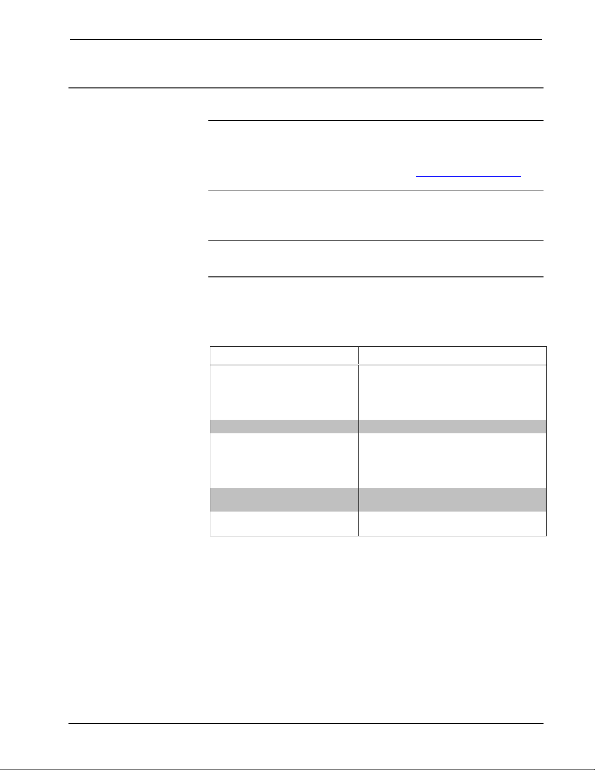
Earliest Version Software Requirements for the PC
NOTE: Crestron recommends that you use the latest software to take advantage of
the most recently released features. The latest software is available from the Crestron
website.
Crestron has developed an assortment of Windows-based software tools to develop
a Cresnet system. The following are the minimum recommended software versions
for the PC:
Software
TASK REQUIRED SOFTWARE VERSION
Program control system to
operate CEN-RGBHV.
Upload program and firmware. Crestron Toolbox 1.06 or later.
Program with simple wizards for
systems using a CEN-RGBHV
(optional but recommended).
Create labels for front panel
buttons.
Manage CEN-RGBHV systems
within a facility (optional)
SIMPL Windows version 2.8.41 or later with
SIMPL+ Cross Compiler version 1.1 or
later. Check the Crestron website for the
latest versions of Library update and
Crestron Database.
Check the Crestron website for the latest
versions of Crestron SystemBuilder™ and
Systembuilder Templates. Refer to software
release notes or Crestron website for other
required Crestron software packages.
Crestron Engraver 3.8.0.1 or later.
RoomView
®
Express version 6.1.0.0.
Programming with Crestron SystemBuilder
Crestron SystemBuilder is the easiest method of programming but does not offer as
much flexibility as SIMPL Windows. For additional details, download
SystemBuilder from the Crestron website and examine the extensive help file.
22 • Wideband RGB Matrix Switcher: CEN-RGBHV Operations Guide – DOC. 6612A
Page 27

Crestron CEN-RGBHV Wideband RGB Matrix Switcher
Programming with SIMPL Windows
NOTE: While SIMPL Windows can be used to program the CEN-RGBHV, it is
recommended to use SystemBuilder for configuring a system.
SIMPL Windows is Crestron’s premier software for programming Crestron control
systems. It is organized into two separate but equally important “Managers”.
Configuration Manager
Configuration Manager is the view where programmers “build” a Crestron control
system by selecting hardware from the Device Library.
• To incorporate the CEN-RGBHV (Cresnet) into the system, drag the
CEN-RGBHV from the Cresnet Control Modules | Cresnet Video Modules
folder of the Device Library and drop it in the System Views.
Locating the CEN-RGBHV (Cresnet) in the Device Library
• To incorporate the CEN-RGBHV (Ethernet) into the system, drag the
CEN-RGBHV from the Ethernet Control Modules | Ethernet Video
Modules folder of the Device Library and drop it in the System Views.
Locating the CEN-RGBHV (Ethernet) in the Device Library
Operations Guide – DOC. 6612A Wideband RGB Matrix Switcher: CEN-RGBHV • 23
Page 28
Wideband RGB Matrix Switcher Crestron CEN-RGBHV
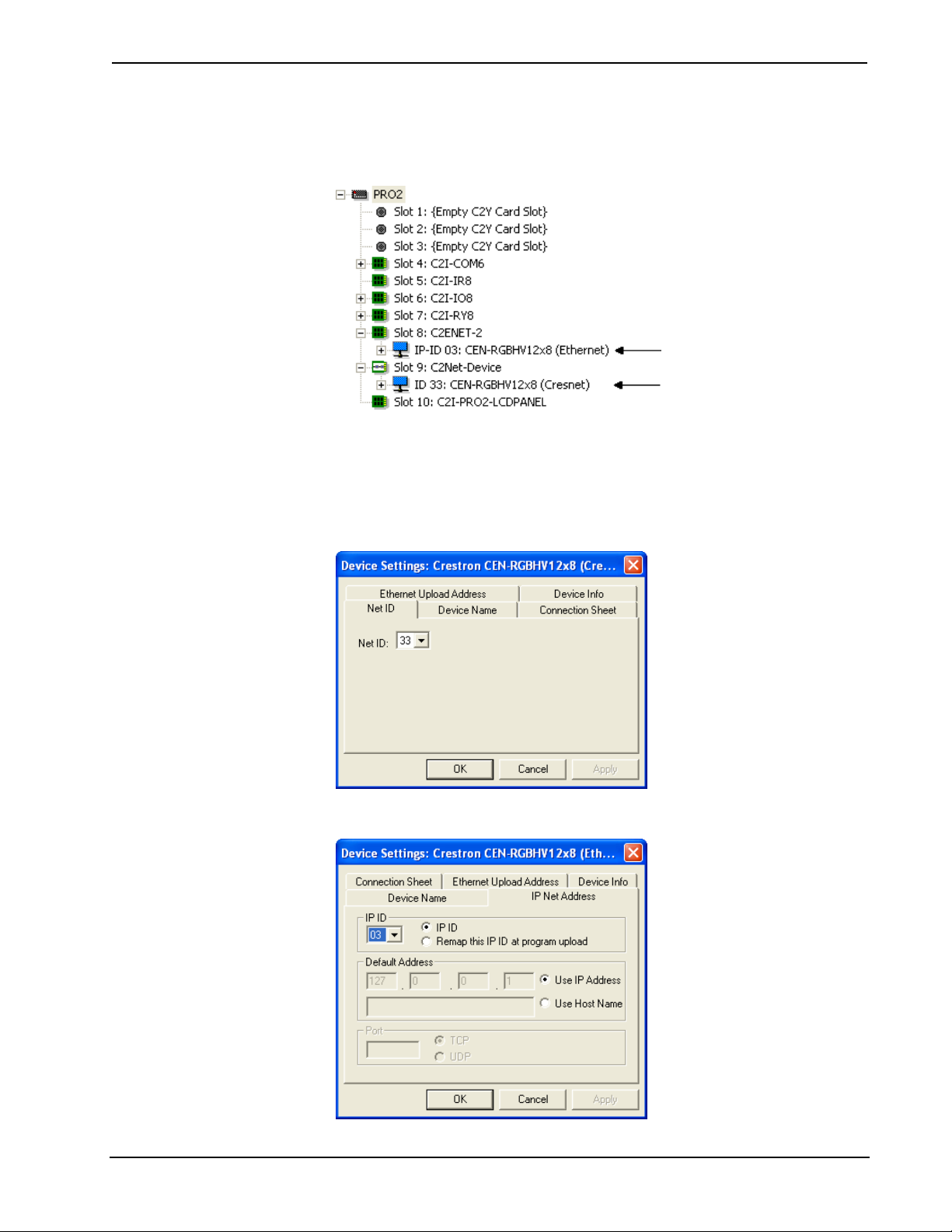
• The system tree of the control system displays the device in the appropriate
slot with a default Net ID or IP ID as shown in the following illustration.
C2Net Device, Slots 8 and 9
• Additional CEN-RGBHV devices are assigned different Net ID or IP ID
numbers as they are added.
• If necessary, double click a device to open the “Device Settings” window
and change the Net ID or IP ID as shown in the following figure.
CEN-RGBHV (Cresnet) “Device Settings” Window
CEN-RGBHV (Ethernet) “Device Settings” Window
24 • Wideband RGB Matrix Switcher: CEN-RGBHV Operations Guide – DOC. 6612A
Page 29

Crestron CEN-RGBHV Wideband RGB Matrix Switcher
• The ID code specified in the SIMPL Windows program must match the Net
ID or IP ID of each unit. Refer to “Identity Code” on page 17.
Program Manager
Program Manager is the view where programmers “program” a Crestron control
system by assigning signals to symbols.
The symbol can be viewed by double clicking on the icon or dragging it into Detail
View. Each signal in the symbol is described in the SIMPL Windows help file (F1).
Example Program
An example program for the CEN-RGBHV is available from the Crestron website
(www.crestron.com/exampleprograms).
Operations Guide – DOC. 6612A Wideband RGB Matrix Switcher: CEN-RGBHV • 25
Page 30
Wideband RGB Matrix Switcher Crestron CEN-RGBHV
Uploading and Upgrading
Crestron recommends using the latest programming software and that each device
contains the latest firmware to take advantage of the most recently released features.
However, before attempting to upload or upgrade it is necessary to establish
communication. Once communication has been established, files (for example,
programs or firmware) can be transferred to the control system (and/or device).
Finally, program checks can be performed (such as changing the device ID or
creating an IP table) to ensure proper functioning.
Establishing Communication
Use Crestron Toolbox for communicating with the CEN-RGBHV; refer to the
Crestron Toolbox help file for details. There are three methods of communication.
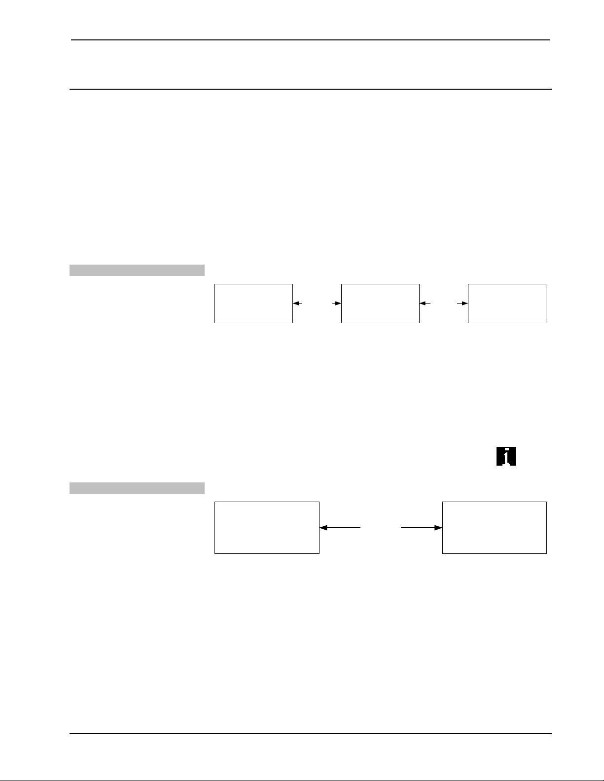
Indirect Communication
TCP/IP Communication
Indirect Communication
PC RUNNING
CRESTRON TOOLBOX
SERIAL,
ETHERNET
OR USB
CONTROL SYSTEM CEN-RGBHV
CRESNET
• CEN-RGBHV connects to control system via Cresnet.
• Establish communication between the PC and the control system as
described in the latest version of the 2-Series Control Systems Reference
Guide (Doc. 6256).
• Use the Address Book in Crestron Toolbox to create an entry for the
CEN-RGBHV using the expected communication protocol (Indirect). Select
the Cresnet ID of the CEN-RGBHV and the address book entry of the
control system that is connected to the CEN-RGBHV.
• Display the CEN-RGBHV’s “System Info” window (click the
communications are confirmed when the device information is displayed.
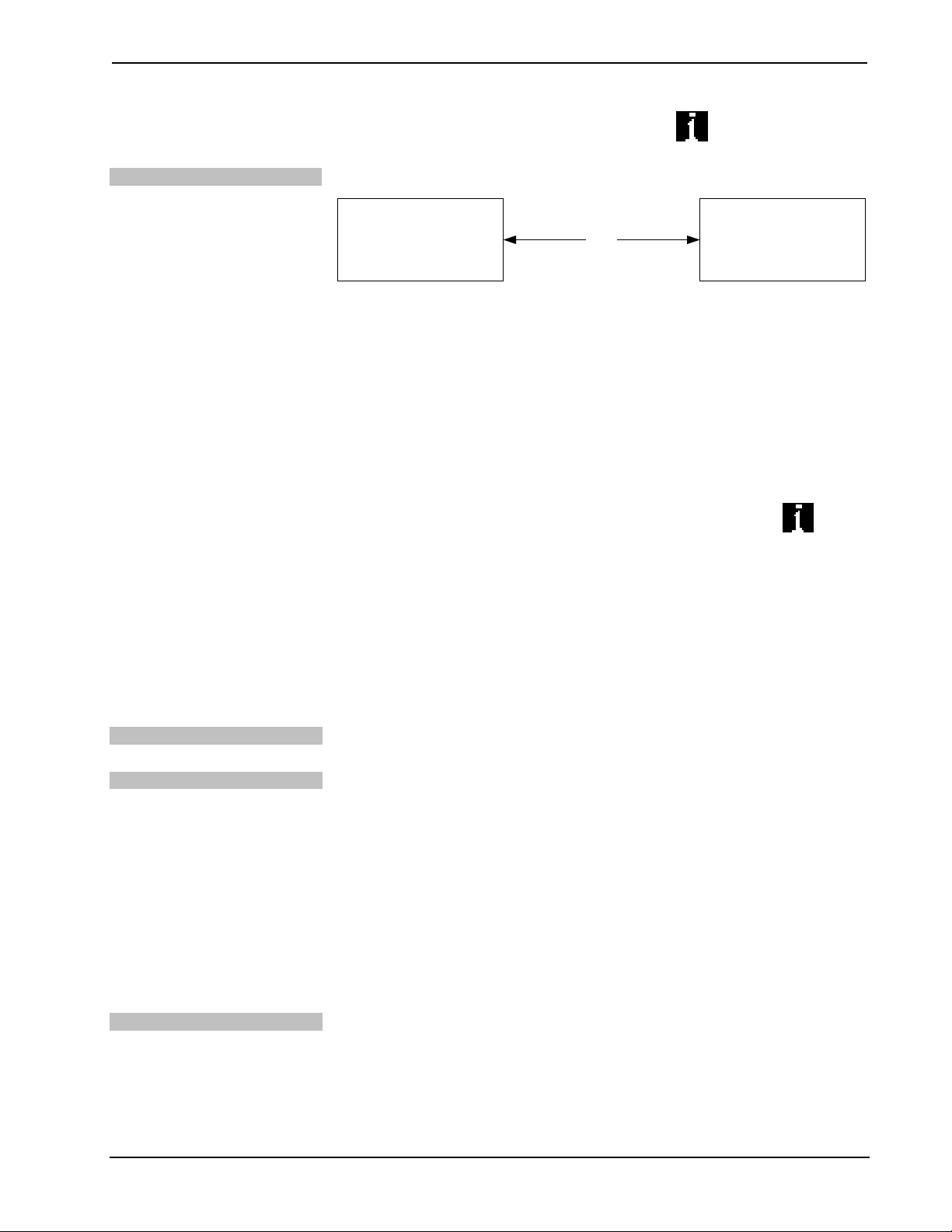
Ethernet Communication
PC RUNNING
CRESTRON TOOLBOX
ETHERNET
CEN-RGBHV
icon);
• Establish serial communication between CEN-RGBHV and PC.
• Enter the IP address, IP mask and default router of the CEN-RGBHV via
the Crestron Toolbox (Functions | Ethernet Addressing); otherwise enable
DHCP.
• Confirm Ethernet connections between CEN-RGBHV and PC. If
connecting through a hub or router, use CAT5 straight through cables with
8-pin RJ-45 connectors. Alternatively, use a CAT5 crossover cable to
connect the two LAN ports directly without using a hub or router.
• Use the Address Book in the Crestron Toolbox to create an entry for the
CEN-RGBHV with the CEN-RGBHV’s TCP/IP communication
parameters.
26 • Wideband RGB Matrix Switcher: CEN-RGBHV Operations Guide – DOC. 6612A
Page 31
Crestron CEN-RGBHV Wideband RGB Matrix Switcher
USB Communication
• Display the “System Info” window (click the
CEN-RGBHV entry.
USB Communication
PC RUNNING
CRESTRON TOOLBOX
• The COMPUTER port on the CEN-RGBHV connects to the USB port on
the PC via the included Type-A to Type B USB cable.
• Use the Address Book in Crestron Toolbox to create an entry using the
expected communication protocol (USB). When multiple USB devices are
connected, identify the CEN-RGBHV by entering “CEN-RGBHV” in the
Model textbox, the unit’s serial number in the Serial textbox or the unit’s
hostname in the Hostname textbox. The hostname can be found in the
“System Info” window in the section marked Ethernet however,
communications must be established in order to see this information in the
“System Info” window.
• Display the CEN-RGBHV’s “System Info” window (click the
communications are confirmed when the device information is displayed.
icon) and select the
CEN-RGBHVUSB
icon);
Programs and Firmware
Program or firmware files may be distributed from programmers to installers or from
Crestron to dealers. Firmware upgrades are available from the Crestron website as
new features are developed after product releases. One has the option to upload
programs via the programming software or to upload and upgrade via the Crestron
Toolbox. For details on uploading and upgrading, refer to the SIMPL Windows help
file or the Crestron Toolbox help file.
SIMPL Windows
Firmware
If a SIMPL Windows program is provided, it can be uploaded to the control system
using SIMPL Windows or Crestron Toolbox.
Check the Crestron website to find the latest firmware. (New users may be required
to register to obtain access to certain areas of the site, including the FTP site.)
Upgrade CEN-RGBHV firmware via Crestron Toolbox.
• Establish communication with the CEN-RGBHV and display the “System
Info” window.
• Select Functions | Firmware… to upgrade the CEN-RGBHV firmware.
Program Checks
Actions that can be performed on the CEN-RGBHV vary depending on whether it is
connected via Cresnet or Ethernet.
Cresnet Connections
For Cresnet connections, using Crestron Toolbox, display the network device tree
(Tools | Network Device Tree) to show all network devices connected to the control
system. Right-click on the CEN-RGBHV to display actions that can be performed on
the CEN-RGBHV.
Operations Guide – DOC. 6612A Wideband RGB Matrix Switcher: CEN-RGBHV • 27
Page 32

Wideband RGB Matrix Switcher Crestron CEN-RGBHV
Ethernet Connections
For Ethernet connections, display the “System Info window (click the
select the Functions menu to display actions that can be performed on the
CEN-RGBHV.
Be sure to use the Crestron Toolbox to create the CEN-RGBHV IP table.
• Select Functions | IP Table Setup.
• Add, modify or delete entries in the IP table. The CEN-RGBHV can have
only one IP table entry.
• A defined IP table can be saved to a file or sent to the device.
Edit the control system’s IP table to include an entry for the CEN-RGBHV. The
entry should list the CEN-RGBHV’s IP ID (specified on the CEN-RGBHV’s IP
table) and the internal gateway IP address 127.0.0.1.
icon) and
28 • Wideband RGB Matrix Switcher: CEN-RGBHV Operations Guide – DOC. 6612A
Page 33

Crestron CEN-RGBHV Wideband RGB Matrix Switcher
Operation
Menu Structure
The overall front panel menu structure of the CEN-RGBHV is shown in the
following illustration. Subsequent paragraphs describe the individual pages and their
functions.
CEN-RGBHV Menu Structure
Setup Menu
Audio Setup
Setup Menu
Video Setup
Setup Menu
Blanking Setup
Setup Menu
Network Setup
Setup Menu
Control Setup
Audio Setup
Input Compensation
Audio Setup
Output Volume
Audio Setup
Input Names
Audio Setup
Ouptut Names
Audio Setup
Audio Blanking
Video Setup
Input Names
Video Setup
Output Names
Video Setup
Video Blanking
Setup and Informational Screens
The following paragraphs describe the various setup and informational screens that
are available with the CEN-RGBHV. These are accessed using the MENU button on
the front panel.
There are five categories within the menu structure:
• Audio Setup
• Video Setup
Network Setup
IP Address
Network Setup
Subnet Mask
Network Setup
Def. Router
Network Setup
DHCP
Network Setup
HostName
Network Setup
MAC Address
Control Setup
Backlight
Control Setup
Password
Control Setup
Info
Control Setup
Defaults
Control Setup
Front Panel
• Blanking Setup
• Network Setup
• Control Setup
When the MENU button is pressed for the first time, the system will display the
main Audio Setup screen. If the setup menus have previously been used, pressing the
MENU button will display the first screen in the last used category. From any of the
top level menus, you can select a different category by using the rotary quick-adjust
knob on the front panel.
NOTE: The ▲and ▼symbols in the lower right corner of the display let you know
if there are screens available above and/or below the presently displayed screen.
To exit the Setup Menu screens, press the MENU button repeatedly until you see the
Exit Setup Menu screen, shown on the following page. (The number of presses
Operations Guide – DOC. 6612A Wideband RGB Matrix Switcher: CEN-RGBHV • 29
Page 34

Wideband RGB Matrix Switcher Crestron CEN-RGBHV
required will depend on how deeply into the menu structure you have navigated.)
Then press the button below Yes.
“Exit Setup Menu” Screen
Exit Setup Menu?
Yes No
Audio Setup
“Audio Setup” Screen
Setup Menu
Audio Setup
Press the ENTER button to select which parameter of the Audio Setup menu you
wish to view. From any of the parameter level menus, you can select a different
parameter by using the rotary quick-adjust knob on the front panel.
Audio:
Input Compensation
For example, pressing the ENTER button from the Audio Setup menu will display
one of the following parameters:
• Input Compensation
• Output Volume
• Input Names
• Output Names
• Audio Blanking.
Using the quick-adjust knob, you can change to any of the other parameters of the
Audio Setup menu. When you see the parameter you wish to enter, press the
ENTER button.
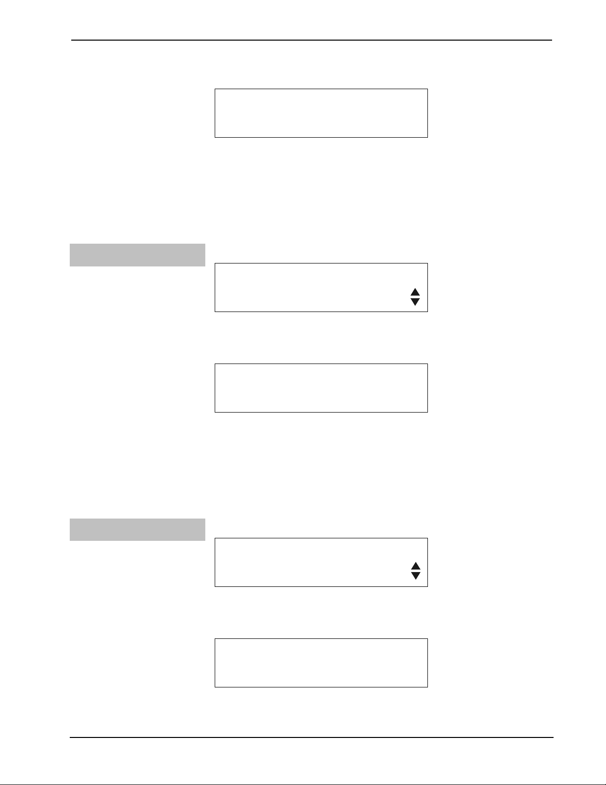
“Input Compensation” Screen
Audio Setup
Input Compensation
Input Compensation allows you to adjust the gain for the selected input. To adjust
input gain, press the ENTER button.
Input Compensation Screen 2
To adjust gain,
press an input
Press the front panel IN button for the input source you wish to adjust.
30 • Wideband RGB Matrix Switcher: CEN-RGBHV Operations Guide – DOC. 6612A
Page 35

Crestron CEN-RGBHV Wideband RGB Matrix Switcher
For example, to raise the input level for the source connected to input number 1,
press the IN button below 1 on the front panel. The LED above IN 1 will light and
the current gain setting for input 1 will be displayed.
“Input 1 Comp.” Screen
Input 1 Comp.
0.0 dB
Use the quick-adjust knob to change the gain. In this example, we will raise the gain
0.5 dB. The display will show the change in gain along with a bar graph.
“Gain” Screen
Gain +0.5 dB
Press ENTER to return the display to the “Input Compensation” screen. Press
ENTER to select another input or use the quick-adjust knob to select another Audio
Setup parameter. The next parameter is Output Volume.
Audio:
Output Volume
“Output Volume” Screen
Audio Setup
Output Volume
To adjust output volume, press the ENTER button.
Output Volume Screen 2
To adjust volume,
press an output
Press the front panel OUT button for the output you wish to adjust.
For example, to lower the output level for output number 1, press the OUT button
below 1 on the front panel. The LED above OUT 1 will light and the current output
level setting for output 1 will be displayed.
“Output 1 Vol.” Screen
Output 1 Vol.
80%
Use the quick-adjust knob to change the output level. In this example, we will lower
the output level by 1%. The display will show the change in output level along with a
bar graph.
Operations Guide – DOC. 6612A Wideband RGB Matrix Switcher: CEN-RGBHV • 31
Page 36

Wideband RGB Matrix Switcher Crestron CEN-RGBHV
“Volume” Screen
Volume: 79%
Press ENTER to return the display to the “Output Volume” screen. Press ENTER to
select another input or use the quick-adjust knob to select another Audio Setup
parameter. The next parameter is Input Names.
Audio:
Input Names
“Input Names” Screen
Audio Setup
Input Names
To set up an input name, press the ENTER button.
“Sel. input to name” Screen
Sel. input to name
1:IN1
Use the quick-adjust knob to select the input you wish to name. Then press ENTER.
Input Name Setup Screen
IN1
Del Ins < >
Use the buttons below the < and > symbols on the display to navigate to the digit you
wish to set. Use the buttons below Del and Ins to delete and/or insert digits. Change
a digit by rotating the quick-adjust knob.
Press ENTER to save the new setting. The display will return to the “Sel. input to
name” screen. Use the quick-adjust knob to select another input or press MENU to
return to the “Input Names” screen. From the “Input Names” screen, use the quickadjust knob to select another Audio Setup parameter. The next parameter is Output
Names.
Audio:
Output Names
“Output Names” Screen
Audio Setup
Ouptut Names
To set up an output name, press the ENTER button.
32 • Wideband RGB Matrix Switcher: CEN-RGBHV Operations Guide – DOC. 6612A
Page 37

Crestron CEN-RGBHV Wideband RGB Matrix Switcher
“Sel. output to name” Screen
Sel. output to name
1:OUT1
Use the quick-adjust knob to select the output you wish to name. Then press
ENTER.
Output Name Setup Screen
OUT1
Del Ins < >
Use the buttons below the < and > symbols on the display to navigate to the digit you
wish to set. Use the buttons below Del and Ins to delete and/or insert digits. Change
a digit by rotating the quick-adjust knob.
Press ENTER to save the new setting. The display will return to the “Sel. output to
name” screen. Use the quick-adjust knob to select another output or press MENU to
return to the “Output Names” screen. From the “Output Names” screen, use the
quick-adjust knob to select another Audio Setup parameter. The next parameter is
Audio Blanking.
Audio:
Audio Blanking
NOTE: Blanking may be enabled/disabled separately for audio and video. Blanking
is used to ensure that no flickering occurs on the video output as the new sync
signals are sent to the display. Audio blanking may be used to mute the audio signal
during video blanking.
“Audio Blanking” Screen
Audio Setup
Audio Blanking
To set audio blanking, press ENTER. Use the quick-adjust knob to turn audio
blanking on or off.
Audio Blanking Screen 2
Audio Blanking
Off
An asterisk to the left of the blanking option will show the current setting.
Audio Blanking Screen 2 (Showing Blanking Set to On)
Audio Blanking
*On
Operations Guide – DOC. 6612A Wideband RGB Matrix Switcher: CEN-RGBHV • 33
Page 38

Wideband RGB Matrix Switcher Crestron CEN-RGBHV
Press ENTER to save the new setting. The display will return to the “Audio
Blanking” screen. Use the quick-adjust knob to select another Audio Setup
parameter or press MENU to return to the “Audio Setup” category screen.
Use the quick-adjust knob to select another category. The next category is Video
Setup.
Video Setup
“Video Setup” Screen
Setup Menu
Video Setup
Press the ENTER button to select which parameter of the Video Setup menu you
wish to view. From any of the parameter level menus, you can select a different
parameter by using the rotary quick-adjust knob on the front panel.
For example, pressing the ENTER button from the Video Setup menu will display
one of the following parameters:
Video:
Input Names
• Input Names
• Output Names
• Video Blanking
Using the quick-adjust knob, you can change to any of the other parameters of the
Video Setup menu. When you see the parameter you wish to enter, press the
ENTER button.
“Input Names” Screen
Video Setup
Input Names
To set up an input name, press the ENTER button.
“Sel. input to name” Screen
Sel. input to name
1:IN1
Use the quick-adjust knob to select the input you wish to name. Then press ENTER.
Input Name Setup Screen
IN1
Del Ins < >
34 • Wideband RGB Matrix Switcher: CEN-RGBHV Operations Guide – DOC. 6612A
Page 39

Crestron CEN-RGBHV Wideband RGB Matrix Switcher
Use the buttons below the < and > symbols on the display to navigate to the digit you
wish to set. Use the buttons below Del and Ins to delete and/or insert digits. Change
a digit by rotating the quick-adjust knob.
Press ENTER to save the new setting. The display will return to the “Sel. input to
name” screen. Use the quick-adjust knob to select another input or press MENU to
return to the “Input Names” screen. From the “Input Names” screen, use the quickadjust knob to select another Video Setup parameter. The next parameter is Output
Names.
Video:
Output Names
“Output Names” Screen
Video Setup
Output Names
To set up an output name, press the ENTER button.
“Sel. output to name” Screen
Sel. output to name
1:OUT1
Use the quick-adjust knob to select the output you wish to name. Then press
ENTER.
Output Name Setup Screen
OUT1
Del Ins < >
Use the buttons below the < and > symbols on the display to navigate to the digit you
wish to set. Use the buttons below Del and Ins to delete and/or insert digits. Change
a digit by rotating the quick-adjust knob.
Press ENTER to save the new setting. The display will return to the “Sel. output to
name” screen. Use the quick-adjust knob to select another output or press MENU to
return to the “Output Names” screen. From the “Output Names” screen, use the
quick-adjust knob to select another Video Setup parameter. The next parameter is
Video Blanking.
NOTE: Blanking may be enabled/disabled separately for audio and video. Blanking
is used to ensure that no flickering occurs on the video output as the new sync
signals are sent to the display. Audio blanking may be used to mute the audio signal
during video blanking.
Video:
Video Blanking
“Video Blanking” Screen
Video Setup
Video Blanking
Operations Guide – DOC. 6612A Wideband RGB Matrix Switcher: CEN-RGBHV • 35
Page 40

Wideband RGB Matrix Switcher Crestron CEN-RGBHV
To set video blanking, press ENTER. Use the quick-adjust knob to turn audio
blanking on or off.
Video Blanking Screen 2
Video Blanking
Off
An asterisk to the left of the blanking option will show the current setting.
Video Blanking Screen 2 (Showing Blanking Set to On)
Video Blanking
*On
Press ENTER to save the new setting. The display will return to the “Video
Blanking” screen. Use the quick-adjust knob to select another Video Setup parameter
or press MENU to return to the “Video Setup” category screen.
Use the quick-adjust knob to select another category. The next category is Blanking
Setup.
Blanking Setup
“Blanking Setup” Screen
Setup Menu
Blanking Setup
To set up blanking, press the ENTER button
Blanking Setup Screen 2
To adjust blanking
select an output
Press the front panel OUT button for the output you wish to adjust.
For example, to set blanking for output number 1, press the OUT button below 1 on
the front panel. The LED above OUT 1 will light and the current blanking setting for
output 1 will be displayed.
“Out 1 Blanking” Screen
** Out 1 Blanking **
0.0 sec
36 • Wideband RGB Matrix Switcher: CEN-RGBHV Operations Guide – DOC. 6612A
Page 41

Crestron CEN-RGBHV Wideband RGB Matrix Switcher
Use the quick-adjust knob to change the blanking time. In this example, we will
change the blanking for output 1 from 0 to 0.5 seconds. The display will show the
change in blanking time along with a bar graph.
“Blanking” Screen
Blanking 0.5 sec
Press ENTER to save the new setting. The display will return to the “Blanking
Setup” screen. Press ENTER to select another output.
Use the quick-adjust knob to select another category. The next category is Network
Setup.
Network Setup
“Network Setup” Screen
Setup Menu
Network:
IP Address
Network Setup
Press the ENTER button to select which parameter of the Network Setup menu you
wish to view. From any of the parameter level menus, you can select a different
parameter by using the rotary quick-adjust knob on the front panel.
For example, pressing the ENTER button from the Network Setup menu will display
one of the following parameters:
• IP Address
• Subnet Mask
• Def. Router
• DHCP
• HostName
• MAC Address
Using the quick-adjust knob, you can change to any of the other parameters of the
Network Setup menu. When you see the parameter you wish to enter, press the
ENTER button.
“IP Address” Screen
Network Setup
IP Address
To set the IP address, press the ENTER button.
Operations Guide – DOC. 6612A Wideband RGB Matrix Switcher: CEN-RGBHV • 37
Page 42
Wideband RGB Matrix Switcher Crestron CEN-RGBHV
IP Address Screen 2
IP Address
[123] 456. 789. 000
Use the quick adjust knob to set the values for the first three digits in the IP address.
Then press ENTER to move the brackets to the next three digits and use the quickadjust knob to set the values for these. Use the ENTER button and quick-adjust knob
to set the values for next two groups of three digits.
Press ENTER to save the IP address. The display will return to the “IP Address”
screen. Use the quick-adjust knob to select another Network Setup parameter. The
next parameter is Subnet Mask.
Network:
Subnet Mask
Network:
Def. Router
“Subnet Mask” Screen
Network Setup
Subnet Mask
To set the subnet mask, press the ENTER button.
Subnet Mask Screen 2
Subnet Mask
[255] 255. 255. 000
Use the quick adjust knob to set the values for the first three digits in the subnet
mask. Then press ENTER to move the brackets to the next three digits and use the
quick-adjust knob to set the values for these. Use the ENTER button and quickadjust knob to set the values for next two groups of three digits.
Press ENTER to save the subnet mask. The display will return to the “Subnet Mask”
screen. Use the quick-adjust knob to select another Network Setup parameter. The
next parameter is Def. Router.
“Def. Router” Screen
Network Setup
Def. Router
To set the default router, press the ENTER button.
Def. Router Screen 2
Def. Router
[123] 456. 789. 000
38 • Wideband RGB Matrix Switcher: CEN-RGBHV Operations Guide – DOC. 6612A
Page 43

Crestron CEN-RGBHV Wideband RGB Matrix Switcher
Use the quick adjust knob to set the values for the first three digits in the default
router. Then press ENTER to move the brackets to the next three digits and use the
quick-adjust knob to set the values for these. Use the ENTER button and quickadjust knob to set the values for next two groups of three digits.
Press ENTER to save the default router. The display will return to the “Def. Router”
screen. Use the quick-adjust knob to select another Network Setup parameter. The
next parameter is DHCP.
Network:
DHCP
“DHCP” Screen
Network Setup
DHCP
To set DHCP, press ENTER. Use the quick-adjust knob to turn DHCP on or off.
DHCP Screen 2
DHCP
Off
An asterisk to the left of the DHCP option will show the current setting.
DHCP Screen 2 (Showing DHCP Set to On)
DHCP
*On
Press ENTER to save the new setting. The display will return to the “DHCP” screen.
Use the quick-adjust knob to select another Network Setup parameter. The next
parameter is HostName.
Network:
HostName
“HostName” Screen
Network Setup
HostName
To view the host name, press ENTER. The display will show the existing host name.
HostName Screen 2
HostName
RGBHV1
To set up the hostname, press ENTER.
Operations Guide – DOC. 6612A Wideband RGB Matrix Switcher: CEN-RGBHV • 39
Page 44

Wideband RGB Matrix Switcher Crestron CEN-RGBHV
HostName Setup Screen
RGBHV1
Del Ins < >
Use the buttons below the < and > symbols on the display to navigate to the digit you
wish to set. Use the buttons below Del and Ins to delete and/or insert digits. Change
a digit by rotating the quick-adjust knob.
Press ENTER to save the new setting. The display will return to the “HostName”
screen. Use the quick-adjust knob to select another Network Setup parameter. The
next parameter is MAC Address.
Network:
MAC Address
“MAC Address” Screen
Network Setup
MAC Address
To display the MAC Address, press ENTER.
Mac Address Screen 2
MAC Address
00.10.6e.05.02.b7
Press MENU to return to the “MAC Address” screen.
Use the quick-adjust knob to select another category. The next category is Control
Setup.
Control Setup
“Control Setup” Screen
Setup Menu
Control Setup
Press the ENTER button to select which parameter of the Control Setup menu you
wish to view. From any of the parameter level menus, you can select a different
parameter by using the rotary quick-adjust knob on the front panel.
For example, pressing the ENTER button from the Control Setup menu will display
one of the following parameters:
• Backlight
• Password
• Info
• Defaults
• Front Panel
40 • Wideband RGB Matrix Switcher: CEN-RGBHV Operations Guide – DOC. 6612A
Page 45
Crestron CEN-RGBHV Wideband RGB Matrix Switcher
Using the quick-adjust knob, you can change to any of the other parameters of the
Control Setup menu. When you see the parameter you wish to enter, press the
ENTER button.
Control:
Backlight
“Backlight” Screen
Control Setup
Backlight
To set the backlight level, press ENTER. Use the quick-adjust knob to set the
backlight level to Low, Medium or High.
Backlight Screen 2
Select Brightness
Bklt Low
An asterisk to the left of the backlight option will show the current setting.
Backlight Screen 2 (Showing Backlight Set to High)
Select Brightness
*Bklt High
NOTE: The backlight setting will be in effect while the unit is on. It is not saved
across reboots.
Press ENTER to return the display to the “Backlight” screen. Use the quick-adjust
knob to select another Control Setup parameter. The next parameter is Password.
Control:
Password
“Password” Screen
Control Setup
Password
To set a password, press ENTER.
Password Screen 2
Del Ins < >
Use the buttons below the < and > symbols on the display to navigate to the digit you
wish to set. Use the buttons below Del and Ins to delete and/or insert digits. Change
a digit by rotating the quick-adjust knob.
Operations Guide – DOC. 6612A Wideband RGB Matrix Switcher: CEN-RGBHV • 41
Page 46
Wideband RGB Matrix Switcher Crestron CEN-RGBHV
Press ENTER to save the new setting. The display will return to the “Password”
screen. Use the quick-adjust knob to select another Control Setup parameter. The
next parameter is Info.
Control:
Info
“Info” Screen
Control Setup
Info
To view information about your CEN-RGBHV, press ENTER.
“Info HW/OPS” Screen
Info
HW OPS
The Info submenu is divided into HW (hardware) and OPS (operation) sections.
To view information about your CEN-RGBHV hardware, press the button below
HW.
“Hardware Version” Screen
Hardware Version: 10001
<< >>
NOTE: Use the buttons below << and >> to scroll through the information on each
screen. In the illustration above and the fourteen that follow, the text has been made
smaller to fit all of the information. The actual screen displays will require scrolling
to see all the information.
Use the quick-adjust knob to view other hardware information parameters or press
MENU to return to the “Info HW/OPS” screen.
“FLASH” Screen
FLASH:
<< >>
Flash “Monitor” Screen
Monitor: 64 KB / 64 KB (100%)
<< >>
42 • Wideband RGB Matrix Switcher: CEN-RGBHV Operations Guide – DOC. 6612A
Page 47
Crestron CEN-RGBHV Wideband RGB Matrix Switcher
Flash “Code” Screen
Code: 458 KB / 1984 KB (23%)
<< >>
Flash “File System” Screen
File System: 68 KB / 6144 KB (1%)
<< >>
“TOTAL FLASH” Screen
TOTAL FLASH: 8192 KB
<< >>
“FLASH unique id” Screen
FLASH unique id: 09b4 2e22 859a 52af
<< >>
“RAM” Screen
RAM:
<< >>
RAM “Code” Screen
Code: 458 KB / 2153 KB (21%)
<< >>
RAM “Initialized Data” Screen
Initialized Data: 6 KB / 2153 KB (0%)
<< >>
RAM “Uninitialized Data” Screen
Uninitialized Data: 1684 KB / 2153 KB (0%)
<< >>
Operations Guide – DOC. 6612A Wideband RGB Matrix Switcher: CEN-RGBHV • 43
Page 48

Wideband RGB Matrix Switcher Crestron CEN-RGBHV
RAM “Heap” Screen
Heap: 534 KB / 28566 KB (1%)
<< >>
RAM “File System” Screen
File System: 0 KB / 2048 KB (0%)
<< >>
“TOTAL RAM” Screen
TOTAL RAM: 32768 KB
<< >>
To view the firmware version and serial number of your CEN-RGBHV, press
MENU to return to the “Info HW/OPS” screen then press the button below OPS.
CEN-RGBHV Firmware and Serial Number Screen
CEN-RGBHV8x8 Wide-Band Switcher [v1.000.000 6, #FFFFFFFF]
<< >>
Press MENU to return to the “Info” screen, then press MENU again to return to the
“Info” screen. Use the quick-adjust knob to select another Control Setup parameter.
The next parameter is Defaults.
Control:
Defaults
“Defaults” Screen
Control Setup
Defaults
To reset factory defaults, press ENTER. Use the quick adjust knob to select whether
to restore defaults for Audio settings only, Video setting only, All settings or select
Abort to maintain the current settings.
Defaults Screen 2 (Showing “Audio settings only” Option)
Restore Defaults
*Audio settings onl
An asterisk to the left of the restore defaults option will show the current setting.
44 • Wideband RGB Matrix Switcher: CEN-RGBHV Operations Guide – DOC. 6612A
Page 49

Crestron CEN-RGBHV Wideband RGB Matrix Switcher
Defaults Screen 2 (Showing “Video settings only” Option)
Restore Defaults
Video settings onl
Defaults Screen 2 (Showing “All settings” Option)
Restore Defaults
All settings
Defaults Screen 2 (Showing “Abort” Option)
Restore Defaults
Abort
Control:
Front Panel
Press ENTER to select the new setting. The display will ask you if you are sure you
want to restore default settings.
“Are you sure?” Screen
Are you sure?
Yes No
To restore defaults, press the button below Yes. After a short pause, the screen will
briefly display a “Restored defaults” message (if you reset any defaults), then return
to the “Defaults” screen. Use the quick-adjust knob to select another Control Setup
parameter. The next parameter is Front Panel.
“Front Panel” Screen
Control Setup
Front Panel
To turn the front panel lock on or off, press ENTER. Use the quick-adjust knob to
set the front panel lock on or off.
Front Panel Screen 2
Front Panel Lock:
*Off
An asterisk to the left of the front panel lock option will show the current setting.
Operations Guide – DOC. 6612A Wideband RGB Matrix Switcher: CEN-RGBHV • 45
Page 50

Wideband RGB Matrix Switcher Crestron CEN-RGBHV
Press ENTER to save the new setting. The display will return to the “Front Panel”
screen. Use the quick-adjust knob to select another Control Setup parameter or press
MENU to return to the “Control Setup” category screen.
You can then use the quick-adjust knob to select another category or press MENU
again to display the “Exit Setup Menu” screen.
Routing Signals
The VIEW button allows you to see which input signals are routed to which outputs.
Pressing the VIEW button will cause the LED above the button to light. The display
will show the “View Mode” screen.
“View Mode” Screen
View Mode
Press input/output
In VIEW mode, pressing any of the numbered IN or OUT buttons will cause the
corresponding LEDs to light, showing the input to output routing.
For example, if you press the IN button 1, the LED above IN 1 will light and the
LEDs above any outputs input 1 is routed to will also light. Or, if you press OUT 2
button, the LED above OUT 2 will light and the light and the LED above the input
that is routed to OUT 2 will also light.
If the A button is pressed when you are in VIEW mode, its LED will light and the
unit will display the audio routing. If the V button is pressed when you are in VIEW
mode, its LED will light and the unit will display the video routing.
Pressing the VIEW button again will toggle the unit to ROUTE mode. In ROUTE
mode, the LED above the VIEW button will not be lit. The display will show the
“Route Mode” screen.
“Route Mode” Screen
Route Mode
Press input/outputs
If the A button is pressed, its LED will light and you can route audio signals. If the V
button is pressed, its LED will light and you can route video signals. If both buttons
are pressed, both LEDs will light and both audio and video signals can be routed
simultaneously.
To route signals, select A, V or both, then press the button for the input signal you
wish to route, followed by the OUT buttons corresponding to the outputs you wish to
route that signal to. Audio and video signals can be routed independently.
The LED below TAKE will blink on and off. Press the TAKE button to execute the
routing you have selected. The TAKE LED will stop blinking when routing changes
have been executed.
To exit VIEW or ROUTE mode, press the MENU button.
46 • Wideband RGB Matrix Switcher: CEN-RGBHV Operations Guide – DOC. 6612A
Page 51

Crestron CEN-RGBHV Wideband RGB Matrix Switcher
Sync Mode
To enter SYNC mode, press the SYNC button. The display will show the “Sync
Mode” screen.
“Sync Mode” Screen
Sync Mode
Press input
To view the horizontal and vertical sync rates of any input, press the numbered IN
button for the input you wish to view. The display will show the horizontal and
vertical sync rates for that input.
For example, to view the sync rates for input number 1, press the IN button below 1
on the front panel. The LED above IN 1 will light and the sync rates for input
number 1 will be displayed.
Sync Screen (Showing Horizontal and Vertical Sync Rates for Input 1)
1HSync 63897Hz
1VSync 60Hz
To refresh the current rate, press the numbered IN button below the selected input
again. A displayed sync rate of 0 Hz, indicates that no sync has been detected.
To view the sync rates for a different input, press the numbered IN button for the
input you wish to view.
To exit SYNC mode, press the SYNC button or press another button such as VIEW
or MENU.
Operations Guide – DOC. 6612A Wideband RGB Matrix Switcher: CEN-RGBHV • 47
Page 52

Wideband RGB Matrix Switcher Crestron CEN-RGBHV
Problem Solving
Troubleshooting
The following table provides corrective action for possible trouble situations. If
further assistance is required, please contact a Crestron customer service
representative.
CEN-RGBHV Troubleshooting
TROUBLE POSSIBLE CAUSE(S) CORRECTIVE ACTION
Use the Right Wire
Strip and Tin Wire
Add Hubs
Device does not
function.
Improper NET ID used.
Poor picture or
sound quality
Device is not
communicating with the
network.
Cables improperly
connected.
Use Crestron Toolbox to poll
the network. Verify network
connection to the device.
Verify that device ID matches
NET ID in the program.
Verify all cables are secure.
Check Network Wiring
In order to ensure optimum performance over the full range of your installation
topology, Crestron Certified Wire and only Crestron Certified Wire may be used.
Failure to do so may incur additional charges if support is required to identify
performance deficiencies because of using improper wire.
When daisy-chaining Cresnet units, strip the ends of the wires carefully to avoid
nicking the conductors. Twist together the ends of the wires that share a pin on the
network connector and tin the twisted connection. Apply solder only to the ends of
the twisted wires. Avoid tinning too far up the wires or the end becomes brittle.
Insert the tinned connection into the Cresnet connector and tighten the retaining
screw. Repeat the procedure for the other three conductors.
For larger networks (i.e., greater than 28 network devices), it may become necessary
to add a Cresnet Hub/Repeater (CNXHUB) to maintain signal quality throughout the
network. Also, for networks with lengthy cable runs it may be necessary to add a
Hub/Repeater after only 20 devices.
Reference Documents
The latest version of all documents mentioned within the guide can be obtained from
the Crestron website (www.crestron.com/manuals). This link will provide a list of
product manuals arranged in alphabetical order by model number.
List of Related Reference Documents
DOCUMENT TITLE
2-Series Control Systems Reference Guide
Crestron e-Control Reference Guide
48 • Wideband RGB Matrix Switcher: CEN-RGBHV Operations Guide – DOC. 6612A
Page 53

Crestron CEN-RGBHV Wideband RGB Matrix Switcher
Further Inquiries
If you cannot locate specific information or have questions after reviewing this
guide, please take advantage of Crestron's award winning customer service team by
calling the Crestron corporate headquarters at 1-888-CRESTRON [1-888-273-7876].
For assistance in your local time zone, refer to the Crestron website
(www.crestron.com/offices
You can also log onto the online help section of the Crestron website
(www.crestron.com/onlinehelp
users will need to establish a user account to fully benefit from all available features.
) for a listing of Crestron worldwide offices.
) to ask questions about Crestron products. First-time
Future Updates
As Crestron improves functions, adds new features and extends the capabilities of
the CEN-RGBHV, additional information may be made available as manual updates.
These updates are solely electronic and serve as intermediary supplements prior to
the release of a complete technical documentation revision.
Check the Crestron website periodically for manual update availability and its
relevance. Updates are identified as an “Addendum” in the Download column.
Operations Guide – DOC. 6612A Wideband RGB Matrix Switcher: CEN-RGBHV • 49
Page 54

Wideband RGB Matrix Switcher Crestron CEN-RGBHV
Return and Warranty Policies
Merchandise Returns / Repair Service
1. No merchandise may be returned for credit, exchange or service without prior authorization
from CRESTRON. To obtain warranty service for CRESTRON products, contact an
authorized CRESTRON dealer. Only authorized CRESTRON dealers may contact the factory
and request an RMA (Return Merchandise Authorization) number. Enclose a note specifying
the nature of the problem, name and phone number of contact person, RMA number and
return address.
2. Products may be returned for credit, exchange or service with a CRESTRON Return
Merchandise Authorization (RMA) number. Authorized returns must be shipped freight
prepaid to CRESTRON, 6 Volvo Drive, Rockleigh, N.J. or its authorized subsidiaries, with
RMA number clearly marked on the outside of all cartons. Shipments arriving freight collect
or without an RMA number shall be subject to refusal. CRESTRON reserves the right in its
sole and absolute discretion to charge a 15% restocking fee plus shipping costs on any
products returned with an RMA.
3. Return freight charges following repair of items under warranty shall be paid by CRESTRON,
shipping by standard ground carrier. In the event repairs are found to be non-warranty, return
freight costs shall be paid by the purchaser.
CRESTRON Limited Warranty
CRESTRON ELECTRONICS, Inc. warrants its products to be free from manufacturing defects in materials
and workmanship under normal use for a period of three (3) years from the date of purchase from
CRESTRON, with the following exceptions: disk drives and any other moving or rotating mechanical
parts, pan/tilt heads and power supplies are covered for a period of one (1) year; touchscreen display and
overlay components are covered for 90 days; batteries and incandescent lamps are not covered.
This warranty extends to products purchased directly from CRESTRON or an authorized CRESTRON
dealer. Purchasers should inquire of the dealer regarding the nature and extent of the dealer's warranty, if
any.
CRESTRON shall not be liable to honor the terms of this warranty if the product has been used in any
application other than that for which it was intended or if it has been subjected to misuse, accidental
damage, modification or improper installation procedures. Furthermore, this warranty does not cover any
product that has had the serial number altered, defaced or removed.
This warranty shall be the sole and exclusive remedy to the original purchaser. In no event shall
CRESTRON be liable for incidental or consequential damages of any kind (property or economic damages
inclusive) arising from the sale or use of this equipment. CRESTRON is not liable for any claim made by a
third party or made by the purchaser for a third party.
CRESTRON shall, at its option, repair or replace any product found defective, without charge for parts or
labor. Repaired or replaced equipment and parts supplied under this warranty shall be covered only by the
unexpired portion of the warranty.
Except as expressly set forth in this warranty, CRESTRON makes no other warranties, expressed or
implied, nor authorizes any other party to offer any warranty, including any implied warranties of
merchantability or fitness for a particular purpose. Any implied warranties that may be imposed by law are
limited to the terms of this limited warranty. This warranty statement supersedes all previous warranties.
Trademark Information
All brand names, product names and trademarks are the sole property of their respective owners. Windows is a registered trademark
of Microsoft Corporation. Windows95/98/Me/XP/Vista and WindowsNT/2000 are trademarks of Microsoft Corporation.
50 • Wideband RGB Matrix Switcher: CEN-RGBHV Operations Guide – DOC. 6612A
Page 55

Crestron CEN-RGBHV Wideband RGB Matrix Switcher
This page is intentionally left blank.
Operations Guide – DOC. 6612A Wideband RGB Matrix Switcher: CEN-RGBHV • 51
Page 56

Crestron Electronics, Inc. Operations Guide – DOC. 6612A
15 Volvo Drive Rockleigh, NJ 07647 (2019030)
Tel: 888.CRESTRON 10.07
Fax: 201.767.7576 Specifications subject to
www.crestron.com change without notice.
 Loading...