

Page 1

CCS-UC-1
Crestron Mercury®
Tabletop Conference System
Supplemental Guide
Crestron Electronics, Inc.
Firmware v1.4095.00091.001 and later
Page 2
Crestron product development software is licensed to Crestron dealers and Crestron Service Providers (CSPs) under a
limited non-exclusive, non-transferable Software Development Tools License Agreement. Crestron product operating system
software is licensed to Crestron dealers, CSPs, and end-users under a separate End-User License Agreement. Both of these
Agreements can be found on the Crestron website at www.crestron.com/legal/software_license_agreement.
The product warranty can be found at www.crestron.com/legal/sales-terms-conditions-warranties.
The specific patents that cover Crestron products are listed at www.crestron.com/legal/patents.
Certain Crestron products contain open source software. For specific information, visit www.crestron.com/legal/open-
source-software.
Crestron, the Crestron logo, .AV Framework, AirMedia, Crestron AirBoard, Crestron Connected, Crestron Fusion, Crestron
XiO Cloud, Crestron Mercury, Crestron XiO Cloud, and PinPoint are either trademarks or registered trademarks of Crestron
Electronics, Inc. in the United States and/or other countries. App Store, and Mac are either trademarks or registered
trademarks of Apple, Inc. in the United States and/or other countries. Appspace is either a trademark or a registered
trademark of Appspace Inc. in the United States and/or other countries. Bluetooth and the Bluetooth logos are either
trademarks of registered trademarks of Bluetooth SIG, Inc. in the United States and/or other countries. Cisco and iOS are
either trademarks or registered trademarks of Cisco Systems, Inc. in the United States and/or other countries. Android,
Google, and Google Play are either trademarks or registered trademarks of Google, Inc. in the United States and/or other
countries. HDMI and the HDMI logo are either trademarks or registered trademarks of HDMI Licensing LLC in the United
States and/or other countries. Active Directory, Microsoft, Microsoft Exchange Server, Microsoft Teams, Office 365, Outlook,
PowerShell, Skype, and Windows are either trademarks or registered trademarks of Microsoft Corporation in the United
States and/or other countries. Wi-Fi and Wi-Fi Direct are either trademarks or registered trademarks of Wi-Fi Alliance in the
United States and/or other countries. Zoom Rooms is either a trademark or registered trademark of Zoom Video
Communications, Inc. in the United States and/or other countries. Other trademarks, registered trademarks, and trade
names may be used in this document to refer to either the entities claiming the marks and names or their products. Crestron
disclaims any proprietary interest in the marks and names of others. Crestron is not responsible for errors in typography or
photography.
This document was written by the Technical Publications department at Crestron.
©2019 Crestron Electronics, Inc.
Page 3

Contents
Introduction 1
Requirements 1
Administrator .................................................................................................................. 1
Operating Environment ................................................................................................. 2
Accessories ....................................................................................................................... 2
Configuration 2
Requirements ................................................................................................................... 2
Connect to the Device ................................................................................................... 2
Log Out from the Device ............................................................................................... 5
Configure the Device ...................................................................................................... 5
HDMI INPUT .............................................................................................................. 5
HDMI OUTPUT .......................................................................................................... 7
NETWORK ................................................................................................................. 8
DEVICE ..................................................................................................................... 16
APPSPACE .............................................................................................................. 31
.AV Framework (AVF) ........................................................................................... 33
AirMedia ................................................................................................................... 52
Crestron Airboard .................................................................................................. 55
Enterprise Deployment Options ................................................................................ 57
Crestron XiO Cloud Service ................................................................................. 57
Crestron Deployment Tool for PowerShell® Software ................................. 60
Operation 61
Introduction ................................................................................................................... 61
The Function Menu ....................................................................................................... 63
Join or Schedule a Meeting ......................................................................................... 64
Reserved (Join a Skype for Business Meeting) ................................................ 64
Available (Create a New Meeting) ..................................................................... 67
Present Content ............................................................................................................ 69
Present via HDMI .................................................................................................. 70
Present Crestron AirBoard Content ................................................................. 70
Present via AirMedia ............................................................................................. 71
Answer a Phone Call .................................................................................................... 78
Not in Use ................................................................................................................ 79
Make a Phone Call ........................................................................................................ 79
Make a Call with an Office Session Initiation Protocol (SIP) System ....... 80
Make a Call with a Bluetooth Phone ................................................................. 82
Supplemental Guide – DOC. 7844L Contents • i
Page 4

Make a Call with a Connected Computer ....................................................... 84
Skype for Business ................................................................................................ 86
Crestron AirBoard Whiteboard Capture ................................................................. 92
Record and Share a Crestron AirBoard Session.............................................. 92
Send a Snapshot .................................................................................................... 94
View Participants ................................................................................................... 95
Invite Remote Participants .................................................................................. 96
Admit Remote Participants ................................................................................. 96
Meeting Conclusion Warning .............................................................................. 97
Run a Web Conference ............................................................................................... 98
Invite the CCS-UC-1 to a Meeting (Schedule the Room) ..................................... 99
Reserve from Skype for Business Program ...................................................... 99
Reserve from Microsoft Outlook ........................................................................ 99
Troubleshooting 100
Appendix: Configure Exchange for Use with CCS-UC-1 101
Enable Resource Account Body for One Touch Join ............................................ 101
ii • Contents Supplemental Guide – DOC. 7844L
Page 5

CCS-UC-1:
Crestron Mercury Tabletop Conference
System
Introduction
The CCS-UC-1 Crestron Mercury® Conference Room System provides a single tabletop
device that allows for room scheduling, presenting, conference calling, and video calling.
For more information on features, capabilities, and specifications on the CCS-UC-1 and
its accessories, visit www.crestron.com/mercury
This supplemental guide discusses the requirements, configuration instructions, and
operating instructions for the CCS-UC-1 in a variety of environments and applications.
For information on installing the CCS-UC-1, refer to the CCS-UC-1 DO Guide (Doc. 7843)
at www.crestron.com/manuals
.
.
Requirements
Administrator
This document is written for use by a facility’s Information Technology (IT)
administrator. The IT administrator should have the following knowledge and skills:
• General Skills
− IP Networking
− Basic PC Operation and Administration
− Basic Smartphone and Tablet Operation
− VoIP system administration (including SIP device management)
− Calendaring system administration (for Exchange connectivity)
• Crestron-specific skills
− Crestron Fusion® software (if applicable)
− Crestron XiO Cloud™ service
Supplemental Guide – DOC. 7844L CCS-UC-1: Crestron Mercury Tabletop Conference System • 1
Page 6
Operating Environment
NOTE: If the CCS-UC-1 is powered with PoE+ (IEEE 820.3at), PoE+ switches that
utilize Link Layer Discovery Protocol (LLDP) must have LLDP enabled. Please
coordinate with the IT Administrator who manages network infrastructure at the
customer site to make sure the PoE+ ports have LLDP enabled. For more information,
refer to “Troubleshooting” on page 100.
The CCS-UC-1 requires the following to make the most of its capabilities.
• Crestron Fusion software
• SIP Server
• Microsoft Exchange Server® software
Accessories
The CCS-UC-1 is available in several different models with a variety of accessories for a
custom installation. Visit www.crestron.com/direct/ccs-uc-1
for more information.
Configuration
Requirements
Configuration requires a computer with web browser software. The CCS-UC-1 and
computer must be connected to a commonly accessible network.
Connect to the Device
To connect to the device, follow this procedure:
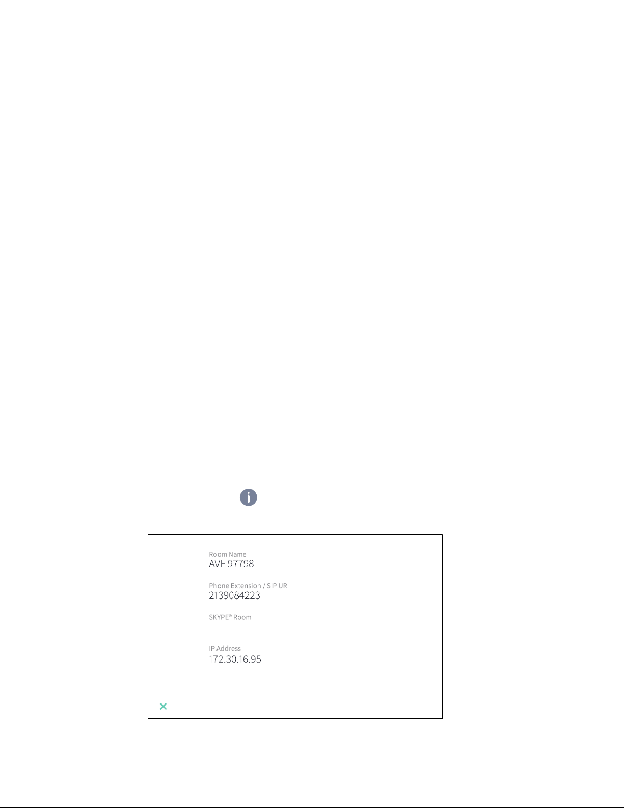
1. On the device, tap . An information screen is displayed.
Information screen
2 • CCS-UC-1: Crestron Mercury Tabletop Conference System Supplemental Guide – DOC. 7844L
Page 7
The information screen lists the Room Name, Phone Extension/SIP URI, SKYPE®
Room (if configured), and IP address.
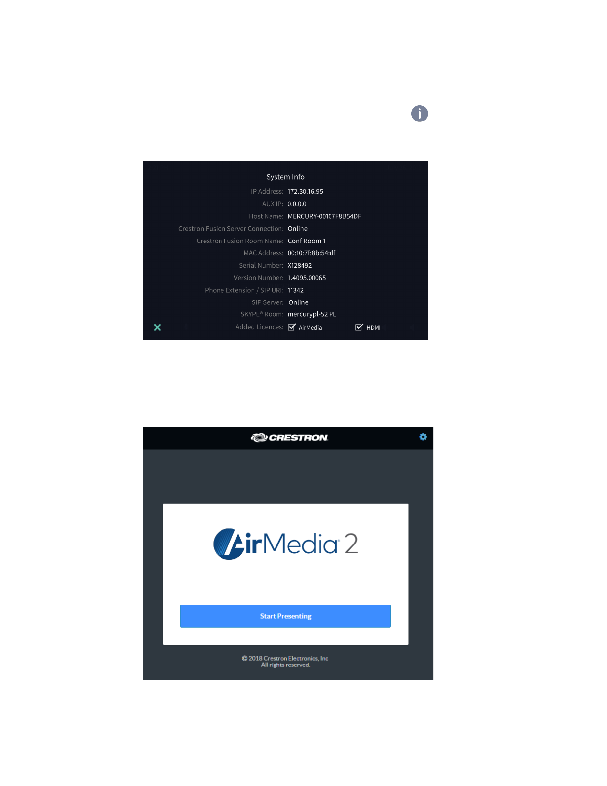
To list additional information, tap X and press and hold for approximately 10
seconds to display the
System Info Screen
System Info screen.
2. Note the IP address and tap X to close the System Info screen.
3. On the computer, open a web browser and navigate to the IP address that was
displayed on the
Welcome Screen
System Info screen. The welcome screen is displayed.
Supplemental Guide – DOC. 7844L CCS-UC-1: Crestron Mercury Tabletop Conference System • 3
Page 8
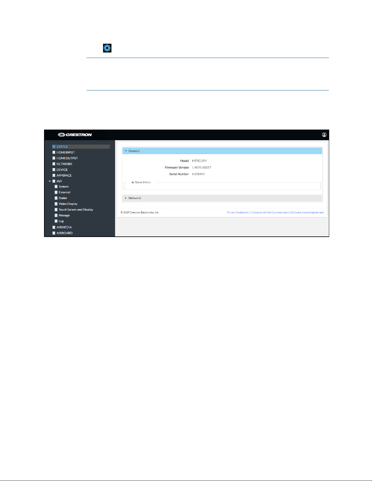
4. Click to continue. A prompt for the user name and password is displayed.
5. Enter the default user name (“admin”) and password (“admin”), and click Sign In
Status Screen
NOTE: Prior to displaying the prompt for login credentials, the web browser may
display a security warning message about the security certificate. It is safe to
ignore this warning as long as the user verifies that the browser’s address bar
indicates the correct IP address or host name of the device.
to continue. The device’s
Status screen is displayed.
The Status screen displays information about the device and allows configuration of the
device’s operating parameters:
• STATUS contains general information about the device and network information.
− Click General to view general information.
− Click Network to view network information.
• HDMI INPUT configures the HDMI® input.
• HDMI OUTPUT displays information about the HDMI output.
• NETWORK configures the device for operation in a network environment.
• DEVICE is used to upload firmware, reboot the device, view the system log,
enable connection to Crestron XiO Cloud service, configure SIP calling
parameters, set the date and time, configure for use with Skype® for Business
software, authentication management, and setting the device to work with
Zoom Rooms™ software.
• APPSPACE is used to configure the device to work with the Appspace® content
management application for digital signage.
• AVF configures the settings for Crestron Fusion integration, power management,
dialing features, video display, touch screen and display functionality, and system
logs.
4 • CCS-UC-1: Crestron Mercury Tabletop Conference System Supplemental Guide – DOC. 7844L
Page 9
• AIRMEDIA configures the device’s AirMedia® presentation gateway functionality.
• AIRBOARD configures the device’s functionality with the CCS-WB-1 Crestron
AirBoard™ whiteboard capture system.
Log Out from the Device
To log out from the device and return to the welcome screen, click .
Configure the Device
Configure the device as required for the installation.
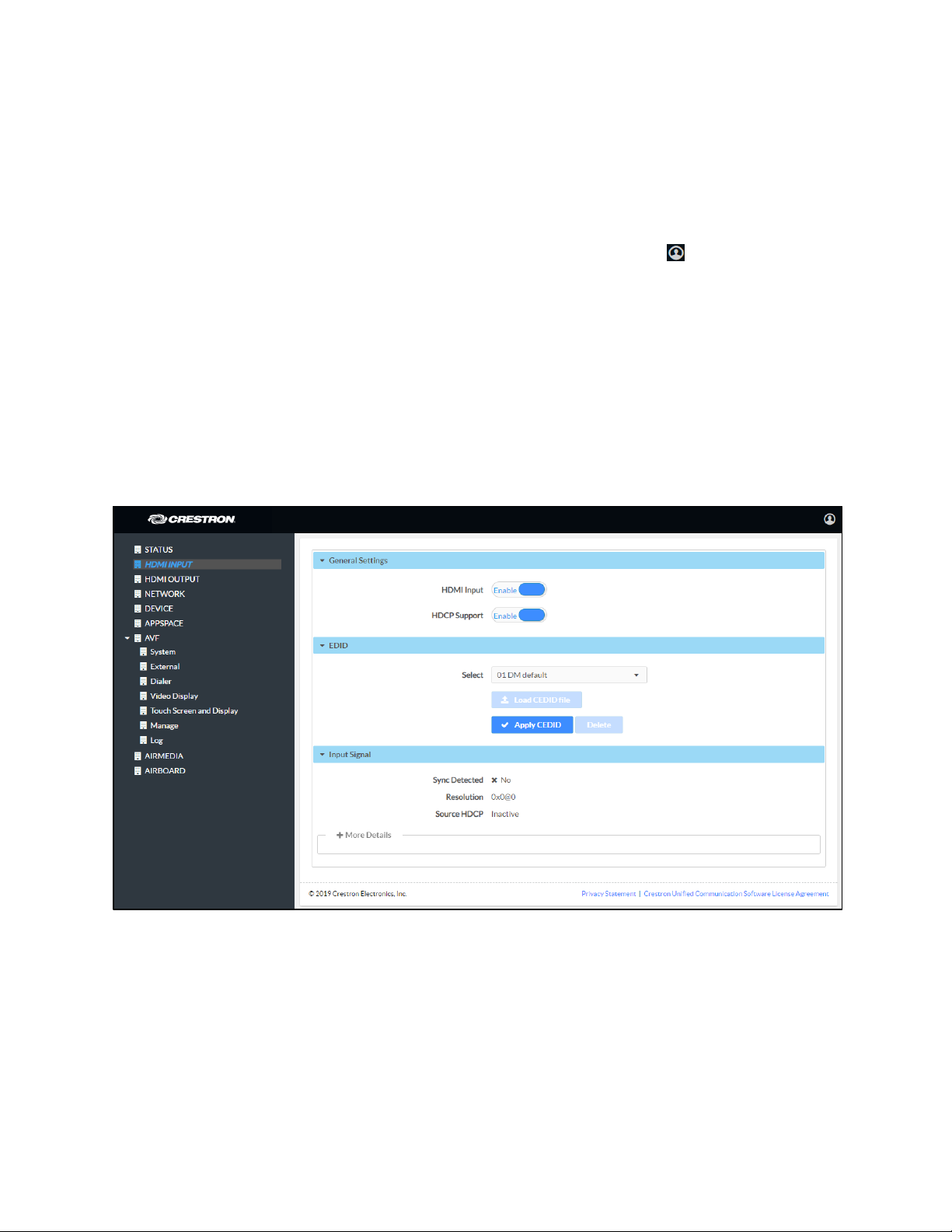
HDMI INPUT
Click HDMI INPUT to configure the HDMI input. The screen displays a selector for HDCP
support, Extended Display Identification Data (EDID) profile selection, and information
about the input signal (if present).
HDMI INPUT Screen
General Settings
HDMI Input
Set HDMI Input to Enable to allow a user to connect their device to the device’s HDMI IN
port. The default setting is
Set HDMI Input to Disable to prevent a user from using an HDMI connection from their
device to the CCS-UC-1.
Supplemental Guide – DOC. 7844L CCS-UC-1: Crestron Mercury Tabletop Conference System • 5
Enable.
Page 10

HDCP Support
Select whether HDCP Support should be set to Enable or Disable. When HDCP support
is enabled, source signals that require HDCP compliance are allowed to pass through to
the display that is connected to the HDMI output. When HDCP support is disabled,
source signals that require HDCP compliance are not allowed to pass through to the
connected display.
NOTE: When HDCP is enabled, the connected display must be HDCP compliant as well.
EDID
EDID is a data structure provided by a digital display to describe its capabilities to a
video source (for example, graphics card or set-top box). It is what enables a computer
to know what kinds of monitors are connected to it.
The EDID section of the HDMI INPUT screen specifies the EDID profile that is selected
for use. Only source devices that use the selected EDID profile are allowed to send
signals through the CCS-UC-1.
To select an EDID profile to support, select one of the profiles from the drop-down list,
and click
If a profile is not listed in the menu, a custom profile can be loaded onto the device. To
load a custom EDID profile, follow this procedure:
Apply EDID.
1. From the Select drop-down list, select Custom.
2. Click Load CEDID file.
3. Click Browse and navigate to the location of the custom CEDID file.
4. Select the file to use and click Open.
5. Click Send EDID.
Input Signal
Click More Details to view details about the input signal connected to the HDMI input
port.
6 • CCS-UC-1: Crestron Mercury Tabletop Conference System Supplemental Guide – DOC. 7844L
Page 11
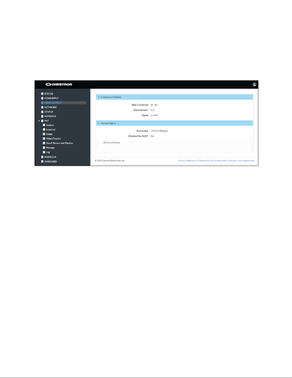
HDMI OUTPUT
Click HDMI OUTPUT to display information about the connected display and output
signal.
Click More Details to view details about the output signal sent to the HDMI output port.
HDMI OUTPUT Screen
Supplemental Guide – DOC. 7844L CCS-UC-1: Crestron Mercury Tabletop Conference System • 7
Page 12
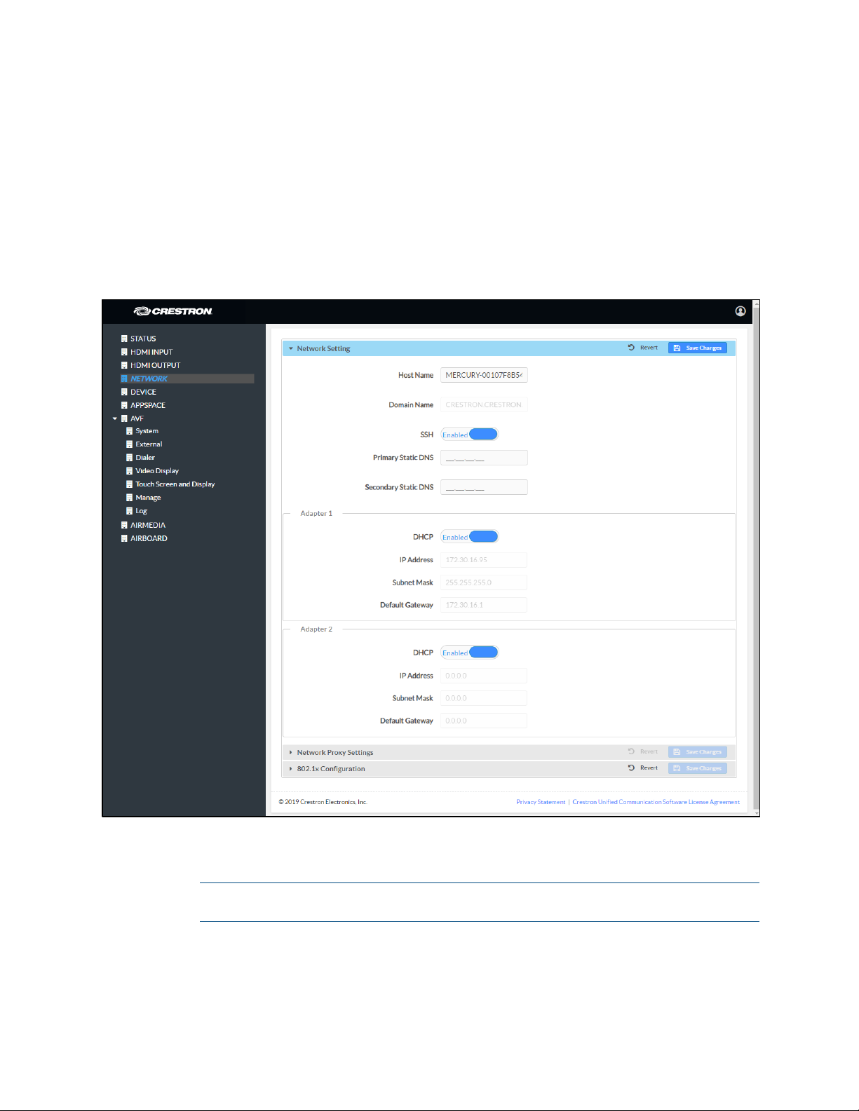
NETWORK
Click NETWORK to configure the device for operating in a network environment. The
screen displays controls for configuring the network settings, network proxy settings,
and 802.1x authentication.
Network Setting
To configure the network settings follow this procedure:
NETWORK Screen - Network Setting
1. Enter a host name in the Host Name field and a domain name (optional) in the
Domain Name field.
NOTE: Use a host name and domain name as an alternative to IP addressing
when connecting client computers to the device.
8 • CCS-UC-1: Crestron Mercury Tabletop Conference System Supplemental Guide – DOC. 7844L
Page 13

2. The CCS-UC-1 has two network adapters, Adapter 1 and Adapter 2. Adapter 1 is
the name assigned to the LAN port and
Adapter 2 is the name assigned to the
AUX port. Each network adapter can be set to have their IP address, subnet
mask, default gateway, and DNS servers set manually, or obtain the settings
from a DHCP server. Choose one of the following options for each network
adapter.
− Set DHCP to Enabled to use a DHCP server to provide the IP address, subnet
mask, default gateway, and DNS server.
− Set DHCP to Disabled to manually enter the Ethernet parameters. When set
to
Disabled, the IP address, subnet mask, default gateway, and DNS servers
must be manually entered.
3. Click Save Changes when done or Revert to return to the previous setting.
NOTE: Any changes made to the network settings will require the device to reboot.
Supplemental Guide – DOC. 7844L CCS-UC-1: Crestron Mercury Tabletop Conference System • 9
Page 14
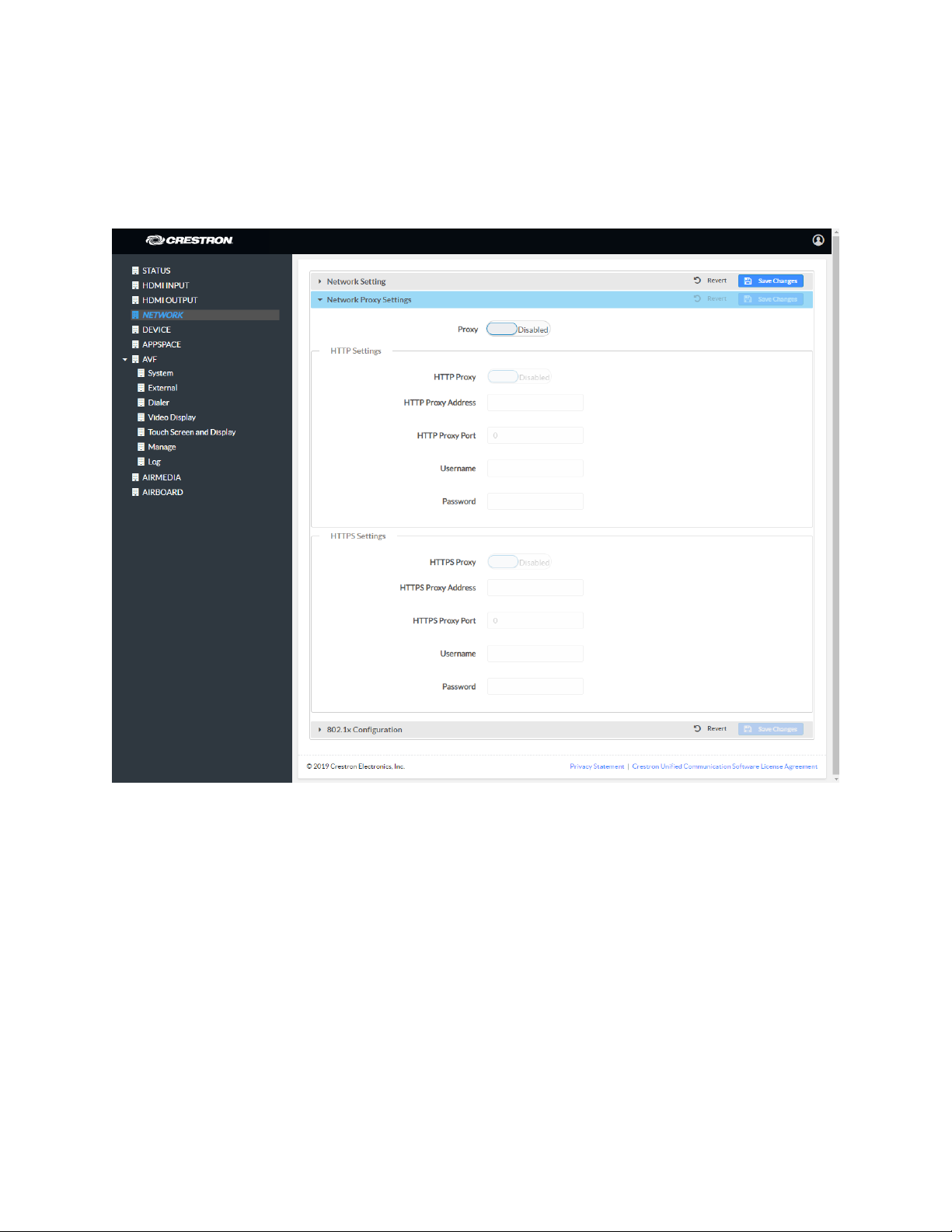
Network Proxy Settings
The CCS-UC-1 can be configured to use a proxy server for http and https
communications. To use a proxy server for network access follow this procedure:
NETWORK Screen – Network Proxy Settings
1. Set Proxy to Enabled.
2. Configure proxy servers for http and https communications in the HTTP Settings
and
HTTPS Settings sections respectively.
− To use an http proxy server:
i. Set HTTP Proxy to Enabled.
ii. Enter the address of the proxy server in the HTTP Proxy Address field.
iii. Enter the port number used by the http proxy server in the HTTP Proxy
Port field.
iv. Enter the username and password in the Username and Password fields.
10 • CCS-UC-1: Crestron Mercury Tabletop Conference System Supplemental Guide – DOC. 7844L
Page 15
− To use an https proxy server:
i. Set HTTPS Proxy to Enabled.
ii. Enter the address of the proxy server in the HTTSP Proxy Address field.
iii. Enter the port number used by the http proxy server in the HTTPS Proxy
Port field.
iv. Enter the username and password in the Username and Password fields.
3. Click Save Changes when done or Revert to return to the previous setting
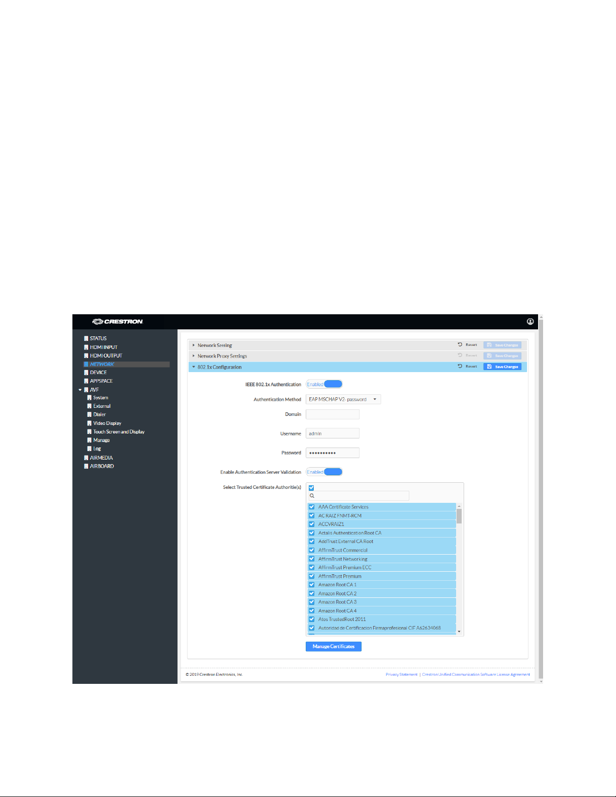
802.1x Configuration
Some networks require devices to use 802.1x port-based network access control for
access to the network.
NETWORK Screen - 802.1x Configuration
To use 802.1x, set IEEE 802.1x Authentication to Enabled and select the desired method
of authentication.
Supplemental Guide – DOC. 7844L CCS-UC-1: Crestron Mercury Tabletop Conference System • 11
Page 16

• Certificate Authentication
a. In the Authentication Method field, select EAP-TLS Certificate.
b. Enter the domain name of the authentication server.
c. Upload a machine certificate.
i. Click Manage Certificates to manage certificates for 802.1x
authentication. A list of certificates is displayed.
Manage Certificates Dialog Box
ii. Click the Machine tab. The current machine certificate is displayed.
iii. Click to delete the certificate from the list of certificates.
iv. Click Add Machine Certificate. The Add Certificate dialog box is
displayed.
Add Certificate Dialog Box
v. Click Browse, select the certificate file, and click Open.
12 • CCS-UC-1: Crestron Mercury Tabletop Conference System Supplemental Guide – DOC. 7844L
Page 17
vi. When prompted, enter the password used to encrypt the file.
vii. Click Load to upload the certificate to the CCS-UC-1. A message
confirming the upload is displayed.
viii. Click OK to close the Add Certificate dialog box.
d. If authentication server validation is not used, set Enable Server Validation
to
Disabled and continue to step 6. Otherwise, set Enable Server Validation
to
Enabled and select the trusted certificate authorities to use.
To select all of the authorities, click the check box next to the search box.
To unselect all of the authorities, click the check box again.
To search for a specific authority, start typing the name of the authority
in the search box and check the box next to the desired authority.
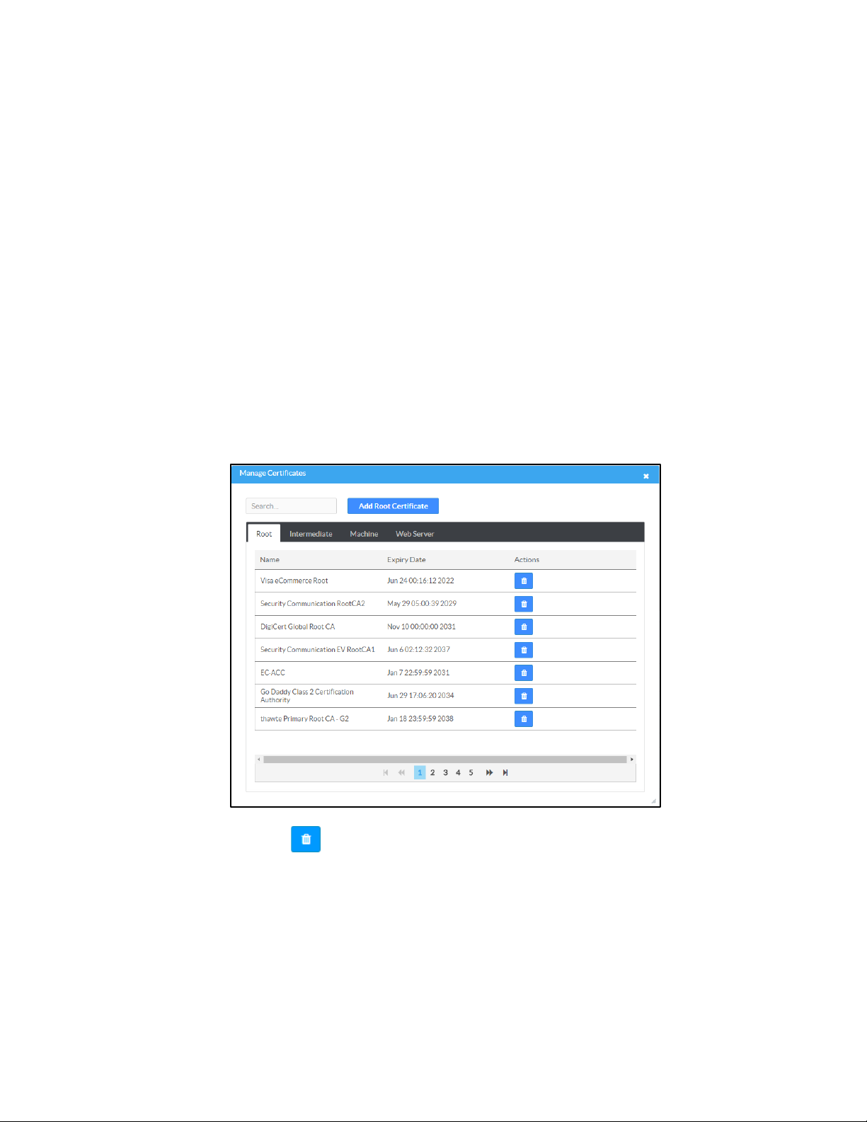
e. Click Manage Certificates to manage certificates for 802.1x authentication.
A list of certificates is displayed.
Manage Certificate Dialog Box
i. Click to delete a certificate from the list of certificates.
Supplemental Guide – DOC. 7844L CCS-UC-1: Crestron Mercury Tabletop Conference System • 13
Page 18

ii. Click Add Root Certificate. The Add Certificate dialog box is displayed.
Add Certificate Dialog Box
iii. Click Browse, select the certificate file, and click Open.
iv. Click Load to upload the certificate to the CCS-UC-1. A message
confirming the upload is displayed.
v. Click OK to close the Add Certificate dialog box.
f. Click Save Changes when done or Revert to return to the previous setting.
• Password Authentication
a. In the Authentication Method field, select EAP-MSCHAP V2-password.
b. Enter the domain name of the authentication server, the user name, and the
password in their respective fields.
c. Set Enable Server Validation to Enabled and select the trusted certificate
authorities to use.
To select all of the authorities, click the check box next to the search box.
To unselect all of the authorities, click the check box again.
To search for a specific authority, start typing the name of the authority
in the search box and check the boxes next to the desired authorities.
14 • CCS-UC-1: Crestron Mercury Tabletop Conference System Supplemental Guide – DOC. 7844L
Page 19
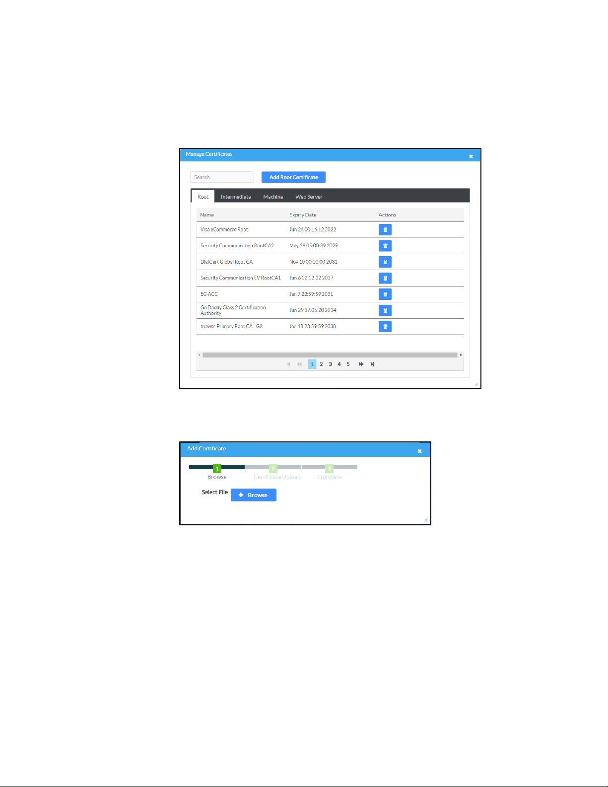
d. To load a custom certificate, click Manage Certificates and follow this
procedure:
i. Click the Root tab to manage certificates for 802.1x authentication.
Manage Certificates Dialog Box: Root Tab
ii. Click Add Root Certificate. The Add Certificate dialog box is displayed.
Add Certificate Dialog Box
iii. Click Browse, select the certificate file, and click Open.
iv. Click Load to upload the certificate to the CCS-UC-1. A message
confirming the upload is displayed.
v. Click OK to close the Add Certificate dialog box.
e. Click Save Changes when done, or Revert to return to the previous setting.
Supplemental Guide – DOC. 7844L CCS-UC-1: Crestron Mercury Tabletop Conference System • 15
Page 20
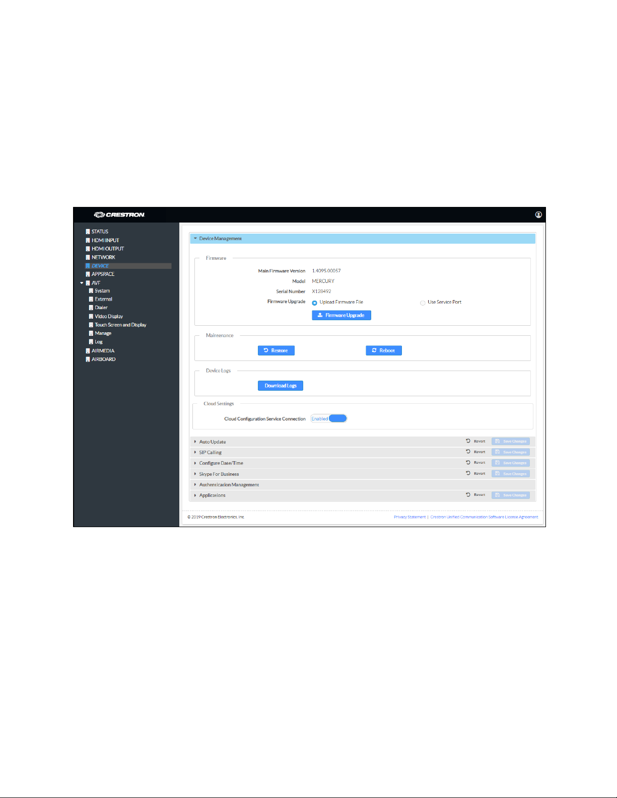
DEVICE
Click DEVICE to upload firmware, restore factory settings, download system logs,
manage cloud settings, manage auto update settings, configure the device for SIP
calling, configure the date and time, configure the device for Skype for Business,
authentication management, and set the device’s application.
Device Management
DEVICE Screen - Device Management
Firmware
To upload device firmware, follow this procedure:
1. Click Firmware Upgrade.
2. Click Browse and navigate to the location of the firmware file.
3. Select the file to use and click Open.
4. Click Load to load the firmware.
16 • CCS-UC-1: Crestron Mercury Tabletop Conference System Supplemental Guide – DOC. 7844L
Page 21
Maintenance
Click Restore to restore the factory settings. Click Reboot to reboot the device.
Device Logs
Click Download Logs to download the device’s system logs to the PC.
Cloud Settings
The Cloud Settings section configures the device’s ability to connect to the cloud and be
managed by the Crestron XiO Cloud service. By default, the
Connection is set to Enabled. To disable the connection, set Cloud Configuration
Service Connection to Disabled. For more information, refer to “Crestron XiO Cloud
Service” on page 57.
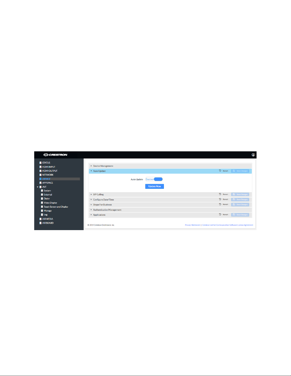
Auto Update
DEVICE Screen - Auto Update
Cloud Configuration Service
The device can automatically check for firmware updates and update as needed. To
allow auto updating, set
Update to Disabled.
To check for available updates, click Update Now.
Supplemental Guide – DOC. 7844L CCS-UC-1: Crestron Mercury Tabletop Conference System • 17
Auto Update to Enabled. To turn off auto updating, set Auto
Page 22
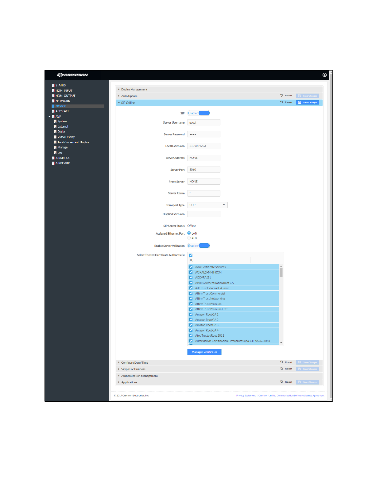
Session Initiation Protocol (SIP) Calling
DEVICE Screen - SIP Calling
To configure the device to make phone calls using a SIP server, follow this procedure:
1. Set SIP to Enabled.
18 • CCS-UC-1: Crestron Mercury Tabletop Conference System Supplemental Guide – DOC. 7844L
Page 23

2. Select the transport protocol to use for SIP calling from the Transport Type
drop-down list. Consult with the VoIP administrator for the proper setting.
3. Enter the IP address of the SIP server in the Server Address field.
4. Enter the port number to be used within the SIP network in the Server Port field.
NOTE: Port 5060 is the default port used by most SIP servers. Check with the
VoIP network administrator for port availability.
5. Enter the user name and password in the Server Username and Server
Password fields.
6. Enter the name of the SIP server realm in the Server Realm field.
NOTE: Many SIP servers do not require a realm and the default value “*” can be
used.
7. Enter the local extension number in the Local Extension field.
8. Enter the SIP proxy server’s IP address or host name in the Proxy Server field.
NOTE: A proxy IP address is not always required. When a proxy IP address is not
required, the default value “NONE” can be used.
9. Select the Ethernet port on the CCS-UC-1 to use for SIP calling. Select LAN if the
LAN port on the CCS-UC-1 connects to the SIP server. Select
AUX if the AUX port
on the CCS-UC-1 connects to the SIP server.
10. If server validation is not used, set Enable Server Validation to Disabled.
Otherwise, set
Enable Server Validation to Enabled and select the trusted
certificate authorities to use.
− To select all of the authorities, click the check box next to the search box. To
unselect all of the authorities, click the check box again.
− To search for a specific authority, start typing the name of the authority in
the search box and check the boxes next to the desired authorities.
Supplemental Guide – DOC. 7844L CCS-UC-1: Crestron Mercury Tabletop Conference System • 19
Page 24
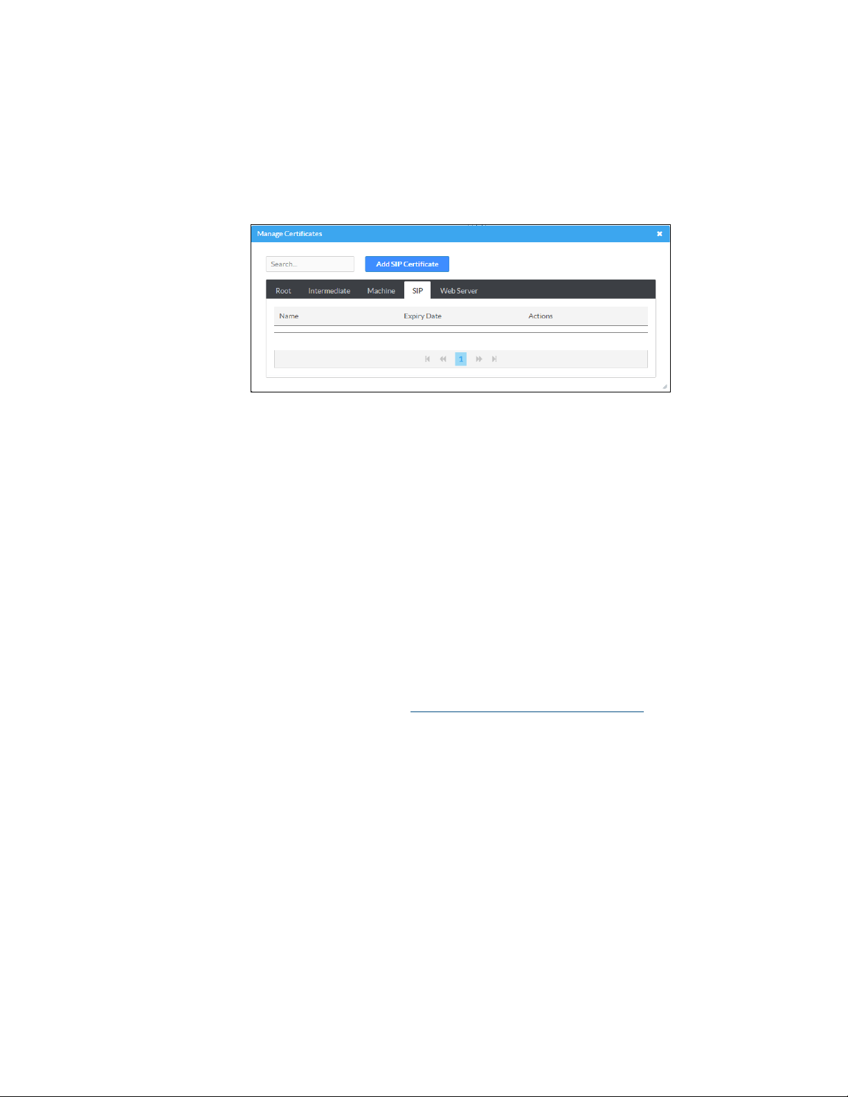
− To load a custom certificate, click Manage Certificates and follow this
procedure:
i. Click the SIP tab to manage certificates for use with a SIP server. If
present, the current SIP certificate is displayed.
Manage Certificates Dialog Box: SIP Tab
ii. Click Add SIP Certificate.
iii. Click Browse, select the certificate file, and click Open.
iv. When prompted, enter the password used to encrypt the file.
v. Click Load to upload the certificate to the CCS-UC-1. A message
confirming the upload is displayed.
vi. Click OK to close the Add Certificate dialog box.
11. Click Save Changes when done or Revert to return to the previous setting. The
device will reboot.
12. Verify the status of the connection to the SIP server in the Status field.
For additional details on configuring the CCS-UC-1 to operate with specific SIP servers,
refer to the DOCUMENTATION tab at www.crestron.com/direct/ccs-uc-1
.
20 • CCS-UC-1: Crestron Mercury Tabletop Conference System Supplemental Guide – DOC. 7844L
Page 25
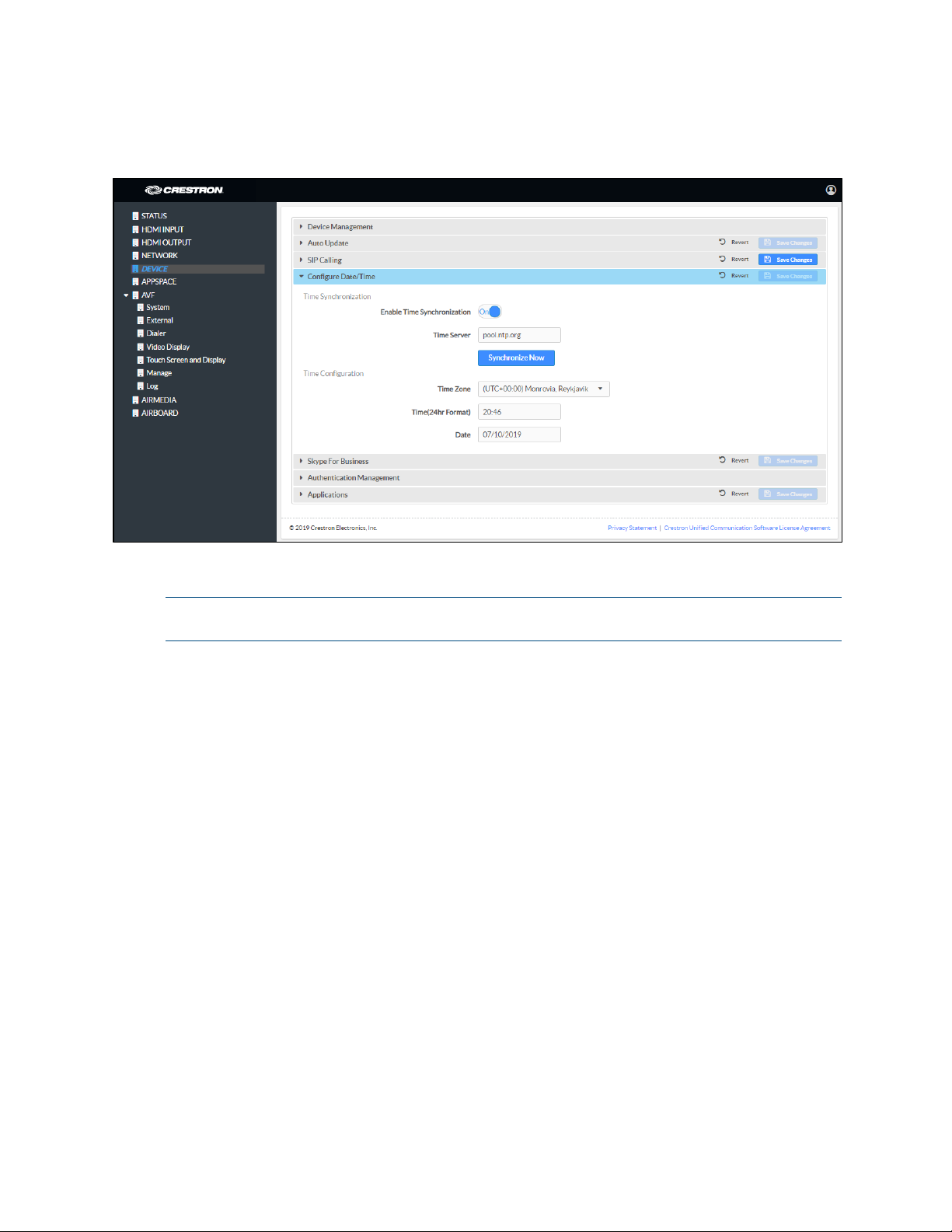
Configure the Date and Time
DEVICE Screen - Configure Date/Time
The device’s internal clock can be synchronized with a time server or set manually.
NOTE: When connected to Crestron Fusion software, the time is automatically set from
the Crestron Fusion software. Any settings made here do not apply.
• Use Time Server Synchronization
a. Set Enable Time Synchronization to On.
b. Enter the time server’s IP address or host name in the Time Server field.
c. Click Synchronize Now to sync Crestron Mercury with the specified time
server.
d. Click Save Changes when done or Revert to return to the previous setting.
• Set the Time Manually
a. Set Enable Time Synchronization to Off.
b. Select the time zone from the Time Zones list.
c. Enter the time (in 24 hour format) in the Time(24hr Format) field.
d. Select the date from the Date field.
e. Click Save Changes when done or Revert to return to the previous setting.
Supplemental Guide – DOC. 7844L CCS-UC-1: Crestron Mercury Tabletop Conference System • 21
Page 26
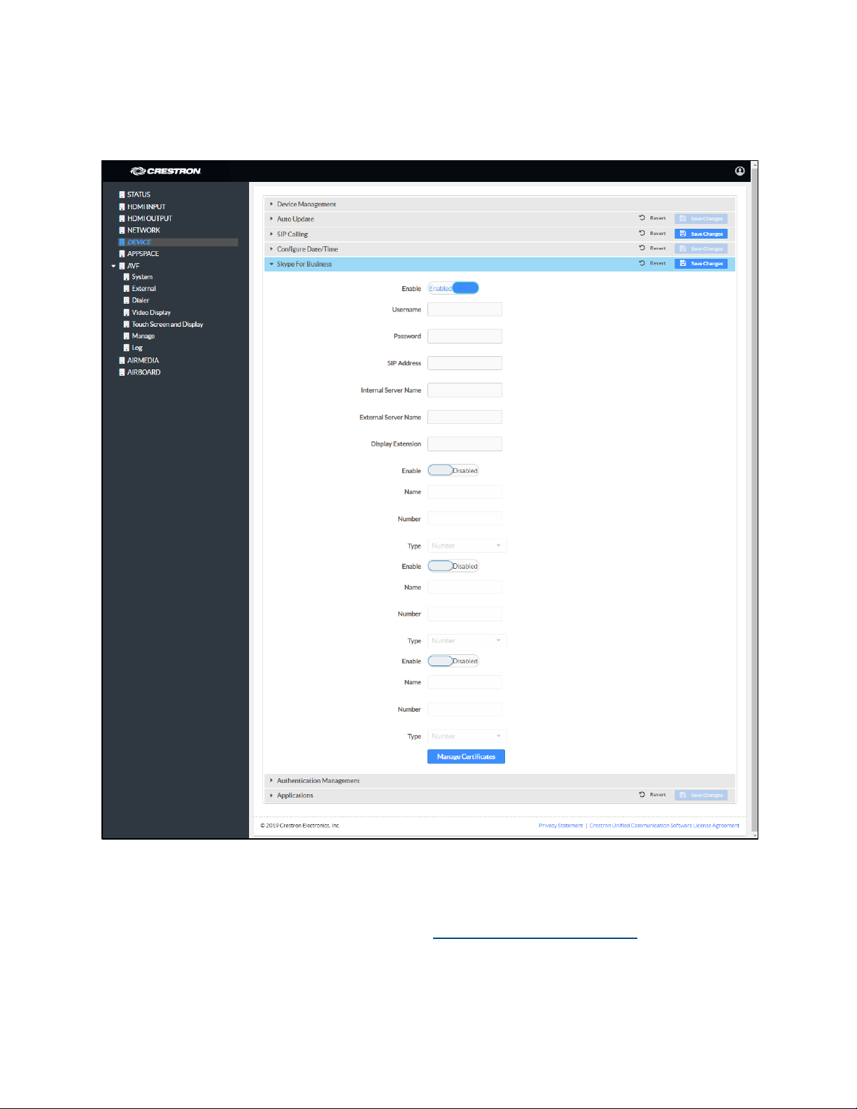
Skype for Business
DEVICE Screen – Skype for Business
®
The CCS-UC-1 can be configured to operate as a Skype
for Business client that can host
meetings, make phone calls, and perform other Skype for Business functions.
For information on supported versions of Skype for Business, refer to Answer ID 5829 in
the Online Help on the Crestron website (www.crestron.com/onlinehelp
22 • CCS-UC-1: Crestron Mercury Tabletop Conference System Supplemental Guide – DOC. 7844L
).
Page 27

Username:
Password
SIP Address
Username
Password
SIP Address
Use the following table and procedure to configure the device for Skype for Business.
Required Fields
USER is HOSTED BY SIP ADDRESS and USER
PRINCIPAL NAME (UPN)
On-premises
Skype for
Business Server
Office 365®
Application
SIP address and UPN may be
the same
SIP address and UPN are
traditionally the characters
before “@onmicrosoft.com”
REQUIRED FIELDS
UPN or domain\username
: Password
: SIP address
: UPN
: Password
: SIP address
1. Set Enable to Enabled.
2. Refer to the table above to determine the required fields and configure the
Username, Password, and SIP Address fields as required.
NOTE: If the Office 365 account uses modern authentication, the login’s
password must be entered on the touch screen after the parameters have been
saved in step
6.
3. If automatic discovery for mobile clients hasn't been configured, enter the
following information:
− Internal Server Name:
https://webdir.online.lync.com/Autodiscover/autodiscoverservice.svc/
Root
− External Server Name:
https://webdir.online.lync.com/Autodiscover/autodiscoverservice.svc/
Root
NOTE: If these fields are left blank, the client uses autodiscovery. If the Skype
for Business deployment does not use autodiscovery, these fields should be
filled with the appropriate information.
These addresses are valid only for
Office 365 users and are different for On-premises Skype for Business Server
deployments.
4. The device can provide up to four speed dial entries. To configure a speed dial
entry, perform the following procedure:
a. Set Enable to Enabled.
b. Enter the “friendly” name of the speed dial entry in the Name field.
c. Enter the email address, phone number, or meeting URL in the Number field.
NOTE: The information entered in the Number field must be formatted for
the selected Type in step d below.
Supplemental Guide – DOC. 7844L CCS-UC-1: Crestron Mercury Tabletop Conference System • 23
Page 28
d. Select the type of entry to be assigned from the Type drop-down list.
Number: Select Number to have the speed dial button dial a phone
number.
Email: Select Email to have the speed dial button create an ad hoc
meeting with a Skype for Business contact’s email address.
URL: Select URL to have the speed dial button automatically join a Skype
for Business meeting.
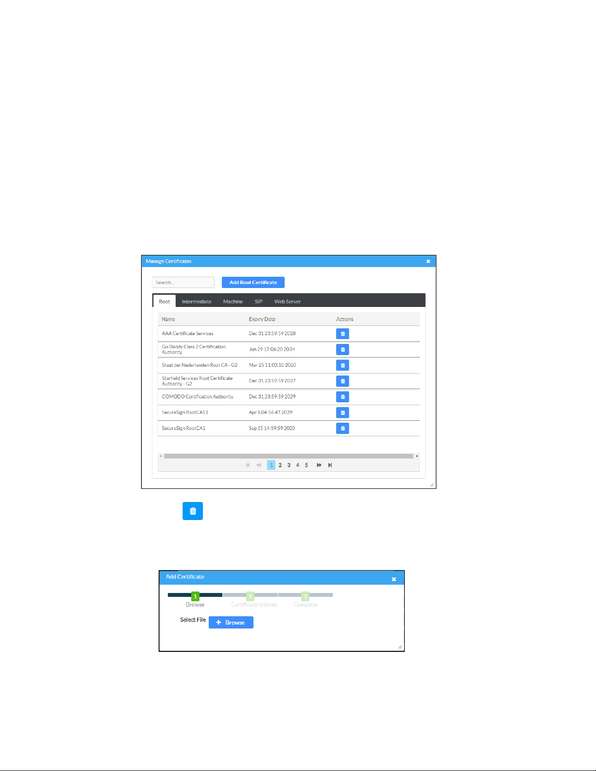
5. If the installation uses an on-premises Skype for Business deployment that
requires a private root certificate, click
Manage Certificates to manage
certificates for authentication. A list of certificates is displayed.
Manage Certificates Dialog Box
a. Click to delete a certificate from the list of certificates.
b. Click Add Root Certificate. The Add Certificate dialog box is displayed.
Add Certificate Dialog Box
c. Click Browse, select the certificate file, and click Open.
24 • CCS-UC-1: Crestron Mercury Tabletop Conference System Supplemental Guide – DOC. 7844L
Page 29
d. Click Load to upload the certificate to the CCS-UC-1. A message confirming
the upload is displayed.
e. Click OK to close the Add Certificate dialog box.
6. Click Save Changes when done or Revert to return to the previous setting.
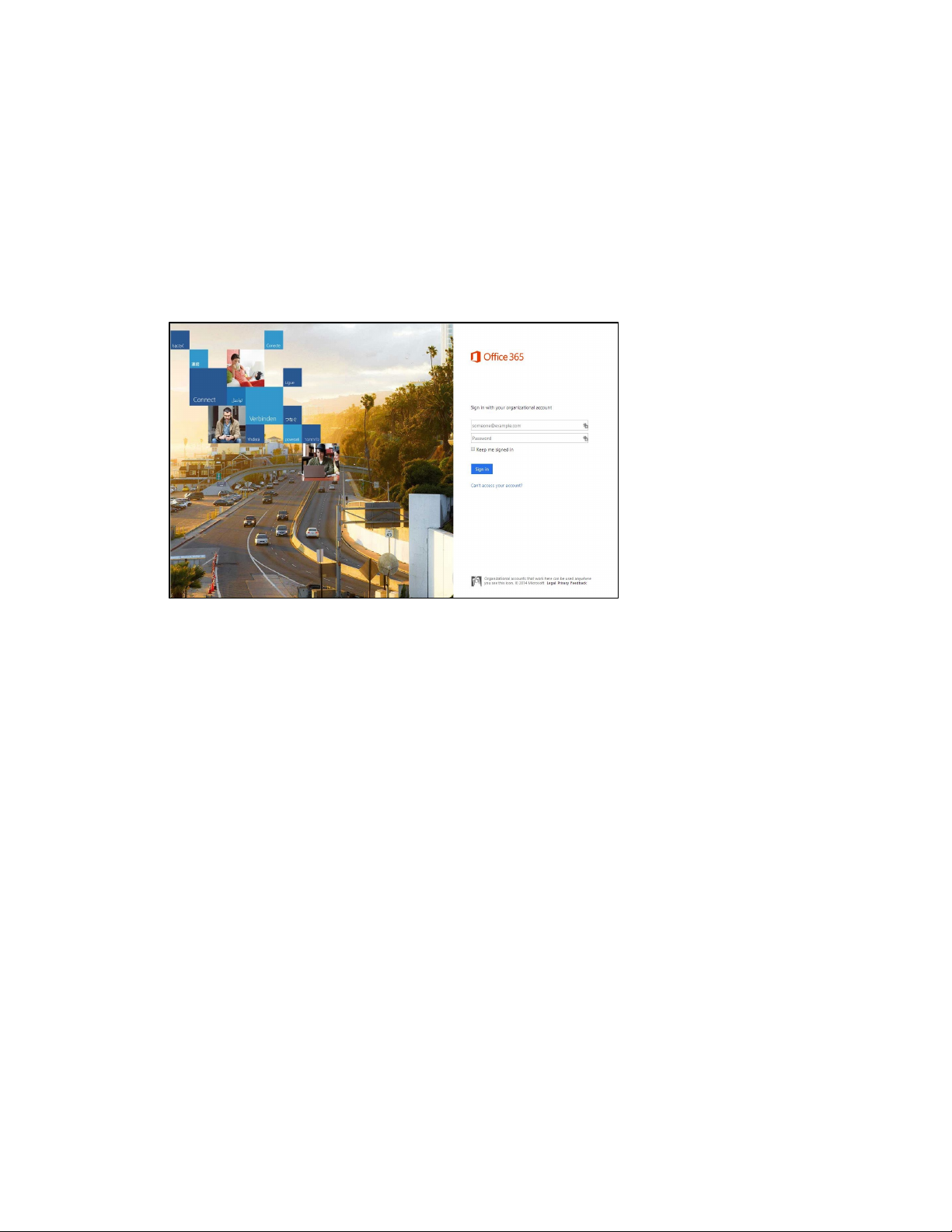
If the Office 365 account uses modern authentication, a login screen is displayed on the
touch screen as shown below.
Office 365 Login Screen
1. Tap inside the password field. A keyboard is displayed.
2. Enter the account password associated with the displayed user name and tap
Go.
Supplemental Guide – DOC. 7844L CCS-UC-1: Crestron Mercury Tabletop Conference System • 25
Page 30

Authentication Management
DEVICE Screen - Authentication Management
This section is used to set the password for the current user, and manage authorized
users and user groups. By default,
Enable Authentication is set to On.
• Current User
a. Click the Current User tab to set the current user’s password.
b. Click Change Current User Password to change the current user’s password.
c. Enter the new password in the Password field.
d. Confirm the new password in the Confirm Password field.
e. Click OK to set the new password or click Cancel to cancel.
26 • CCS-UC-1: Crestron Mercury Tabletop Conference System Supplemental Guide – DOC. 7844L
Page 31

• Users
Click the Users tab to manage authorized users. A list of authorized users is
displayed.
DEVICE Screen - Authentication Management: Users Tab
− Click to view details about a user.
− Click to update a user’s information.
− Click to delete the user from the list of authorized users.
− Click Create User to add a user. The Create User dialog box is displayed.
Create User Dialog Box
i. Enter the user name in the Name field.
ii. Enter the user password in the Password field.
iii. Confirm the password in the Confirm Password field.
iv. Select the user’s group memberships from the Groups drop-down list.
v. Select whether the user is a member of the Active Directory® credential
management group with the
Active Directory Group switch.
vi. Click OK to save the user or click Cancel to cancel.
Supplemental Guide – DOC. 7844L CCS-UC-1: Crestron Mercury Tabletop Conference System • 27
Page 32

• Groups
Click the Groups tab to configure user groups. A list of user groups is displayed.
DEVICE Screen - Authentication Management: Groups Tab
− Click to view details about a group.
− Click to delete the group from the list of groups.
− Click Create Group to add a group to the list of user groups. The Create
Group dialog box is displayed.
Create Group Dialog Box
i. Enter the group name in the Name field.
ii. Select the group’s access level from the Access Level drop-down list.
• Administrator grants full access to the system settings and device
functions
• Connect grants access to the device functions
• Operator grants read access to the system settings and full access to
the device functions
28 • CCS-UC-1: Crestron Mercury Tabletop Conference System Supplemental Guide – DOC. 7844L
Page 33

• Programmer grants access to program/project specific
settings/ReadOnly to the rest, read/write access to the file system, no
access to the setup project
• User grants access to the device functions
iii. Click OK to save the group or click Cancel to cancel.
Applications
DEVICE Screen - Applications
This section is used to select the application to run. The device can run one of three
application modes:
• Select Crestron Default to have the device work as described in “Operation” on
page 61.
• Select Zoom Rooms to have the device work as a Zoom room controller used to
control a Zoom room conference system.
For more information on using the CCS-UC-1 as a Zoom room controller, refer to
https://www.crestron.com/Products/Featured-Solutions/Zoom-Room-Solutions
and
https://support.crestron.com/app/answers/answer_view/a_id/5829#MercuryZo
om.
• Select Teams Video to have the device work as a controller for a Crestron Flex
UC system with Microsoft Teams® software. Settings for using the device as part
of a Crestron Flex UC system are displayed.
NOTE: After selecting Teams Video, click Save Changes and allow the device to
reboot. After the reboot is complete, the Teams Video settings can be specified.
Supplemental Guide – DOC. 7844L CCS-UC-1: Crestron Mercury Tabletop Conference System • 29
Page 34

DEVICE Screen – Applications (Teams Video Settings Shown)
To configure the device for use with a Crestron Flex Microsoft Teams UC system,
enter the following information:
− Teams Video PC Address: Enter the IP address or host name of the
UC-ENGINE running Microsoft Teams software.
NOTE: The host name is printed on a label on the UC-ENGINE or
UC-ENGINE-SD (mounted on the UC-BRKT-100-ASSY or
UC-BRKT-100-SD-ASSY). For more information, refer to the UC-M150-T
Quick Start (Doc. 8366) or UC-M130-T Quick Start (Doc. 8464) at
www.crestron.com/manuals.
− Teams Video Port: By default, port number 49500 is used. If a different port
number has been configured on the PC running Microsoft Teams software,
enter it here.
− Teams Video Username: Enter the login username for the Microsoft Teams
software host PC. (The default username is “admin”.)
− Teams Video Password: Enter the login password for the Microsoft Teams
software host PC. (The default password is “sfb”.)
For more information on configuring a Crestron Mercury UC system with
Microsoft Teams software, refer to the UC Video Conference Systems for
Microsoft Teams Supplemental Guide (Doc. 8360) at
www.crestron.com/manuals
.
Click Save Changes when done or Revert to return to the previous setting. The device
will reboot.
30 • CCS-UC-1: Crestron Mercury Tabletop Conference System Supplemental Guide – DOC. 7844L
Page 35

APPSPACE
The CCS-UC-1 can display content from an Appspace account when the device is not in
use (determined by the built-in occupancy sensor).
NOTES:
• An active Appspace account is required.
• Appspace video service is not supported.
• To use Appspace when the device is in Standby, the Power Settings must be set
to “
34
Click APPSPACE to configure the device’s operation with the Appspace platform.
APPSPACE Screen
Occupancy Based With Signage” as described in “Power Settings” on page
.
To configure the device for use with Appspace:
1. Set Appspace Integration to Enabled to enable Appspace when the CCS-UC-1
goes to sleep based on occupancy (Standby). When enabled, the display on the
CCS-UC-1 turns off and the connected display will show Appspace content.
NOTE: To use Appspace when the device is in Standby, the Power Settings must
be set to “Occupancy Based With Signage” as described in “Power Settings” on
page 34
.
2. Choose the Account Location.
− Public Cloud: Select this option to use the Appspace public web app.
− Private Instance: Select this option to use a privately hosted instance of the
Appspace web app.
3. Enter the Appspace App URL. This is the URL where a privately hosted instance
of the Appspace web app can be found. Leave blank if the
Public Cloud account
location is selected.
Supplemental Guide – DOC. 7844L CCS-UC-1: Crestron Mercury Tabletop Conference System • 31
Page 36

4. Set Signage in Standby to Enabled to display Appspace content when the
CCS-UC-1 goes to sleep based on occupancy. Set to
feature.
5. Set Signage as a Background to Enabled to display Appspace content on the
connected display behind the calendar, date/time, system name, connection info
and branding portions of the display.
NOTE: When set to Enabled, the Enable Custom Backgrounds and Interval
Between Backgrounds options on the Room Schedule screen (described in
“Display Customization” on page 49) are disabled.
6. Click Save Changes when done or Revert to return to the previous setting.
Disabled to turn off the
32 • CCS-UC-1: Crestron Mercury Tabletop Conference System Supplemental Guide – DOC. 7844L
Page 37

.AV Framework (AVF)
Click AVF to configure the device’s .AV Framework™ platform functionality. Click H to
display links for configuring system settings, controlling Crestron Fusion® and calendar
settings, configuring the dialer, configuring the connected video display, configuring
touch screen and connected display operation, managing the system’s configuration, and
viewing activity logs.
System
The System screen specifies the room name, the local language setting, the time format,
the date format, and manages the power settings.
AVF Screen - System
Supplemental Guide – DOC. 7844L CCS-UC-1: Crestron Mercury Tabletop Conference System • 33
Page 38

System Settings
To configure the system settings, follow this procedure:
1. Click System to display the AVF (System) screen.
2. In the Room Name field, enter the name of the room where the device is
installed.
3. In the Language field, select the local language from the drop-down list.
4. In the Time Format field, select the time format from the drop-down list (12 hour
or
24 hour).
5. In the Date Format field, select the date format from the drop-down list.
Power Settings
Configure power settings to manage the system’s power usage. To configure the power
settings, follow this procedure:
1. Select one of the following modes from the Standby drop-down list.
− Always On sets the following:
The connected display will be on during business hours (defined in step 2).
The system will wake up based on occupancy outside of business hours.
The touch screen will always be on.
Changes reported by the built-in occupancy sensor will be ignored.
− Based on Occupancy sets the following:
The built-in occupancy sensor will be used to determine when the room is
occupied or vacant.
When the room is occupied the system will be on.
When the room is vacant the system will be off.
The connected display will be on when the room is occupied and off when
the room is vacant.
The touch screen will be on when the room is occupied and off when the
room is vacant.
Crestron Fusion power events will be ignored.
Connecting an active HDMI input source will turn on the room.
Connecting to the device by an AirMedia connection will not turn on the
room.
34 • CCS-UC-1: Crestron Mercury Tabletop Conference System Supplemental Guide – DOC. 7844L
Page 39

Front Display Content During Standby
Allow Fixed Schedule Power Control
Allow Occupancy Power Control
− Occupancy Based With Signage sets the following:
The built-in occupancy sensor will be used to determine when the room is
occupied or vacant.
When the room is occupied the system will be on.
When the room is vacant, the system will be operating in standby mode
during defined business hours and off outside of business hours (defined
in step 2).
The connected display will be on when the system is in standby mode, and
off when the system is off.
The touch screen will be on when the room is occupied, and off when the
room is vacant.
When in the standby mode, digital signage that is configured to run
during standby mode will be displayed.
Crestron Fusion power events will be ignored.
Connecting an active HDMI input source will not turn on the room.
Connecting to the device by an AirMedia connection will not turn on the
room.
NOTE: This setting must be selected if Appspace is to be used.
2. For each day of the week, define business hours:
− Enable sets whether the day is part of the business hours schedule. Set the
switch to
the switch to
Enable to have the day included in the business hours schedule. Set
Disable to remove the day from the business hours schedule.
− Display On sets the time the connected display will turn on. To set the on
time, click the hour, then click the exact time.
− Display Off sets the time the connected display will turn off. To set the off
time, click the hour, then click the exact time.
3. Click Save to save the settings.
The following table shows each power option’s ability for each Standby setting.
Operation versus Standby Setting
Standby Setting
OPERATION Always On Occupancy Based Occupancy Based
With Signage
Always On
Supplemental Guide – DOC. 7844L CCS-UC-1: Crestron Mercury Tabletop Conference System • 35
Page 40

External
The External screen displays the settings for operating with Crestron Fusion.
AVF Screen - External
Crestron Fusion Settings
To configure the Crestron Fusion settings, follow this procedure:
1. In the Crestron Fusion Room Name field, enter the name to be used by the
Crestron Fusion server.
2. In the IPID field, enter the IP ID number to be used by the Crestron Fusion server.
3. In the Crestron Fusion Cloud URL field, click Enable to allow autodiscovery by
the Crestron Fusion server.
4. Click Save to save the settings or click Disable to disable the settings.
Upon completion, the device should be brought into Crestron Fusion software as a
processor. For details, refer to the Crestron Fusion help file.
Calendar Settings
To configure the calendar settings, follow this procedure:
1. Select the scheduling type from the drop-down list.
− Select Crestron Fusion to use Crestron Fusion for calendar functions.
36 • CCS-UC-1: Crestron Mercury Tabletop Conference System Supplemental Guide – DOC. 7844L
Page 41

− Select SchedulingType Exchange to use Microsoft Exchange Server for
calendar functions.
i. Enter the URL of the Exchange server in the Exchange EWS URL field.
ii. Enter the domain name used by the Exchange server in the Domain field.
iii. Enter the name of the conference room in the Username field.
iv. Enter the password of the conference room in the Password field.
v. Enter the Calendar email address in the Calendar email address field.
NOTE: The Calendar email address is required only for accounts using
Impersonation.
vi. (Optional) Check the Outlook Use Certificate box to use an Outlook®
certificate. Click
certificate.
Upload and follow the instructions to upload a
For more information, refer to Answer IDs 5829 and 5830 in the Online Help
on the Crestron website (www.crestron.com/onlinehelp
2. Click Save to save the settings or click Disable to disable the settings.
For additional information on configuring Exchange or Office 365 with the CCS-UC-1,
refer to “Appendix: Configure Exchange for Use with CCS-UC-1” on page 101.
).
Dialer
The Dialer screen configures the Bluetooth® connectivity settings, the speed keys for
quick dialing via SIP, one-touch keys for initiating phone calls for a meeting, and
configures the device to use Lightweight Directory Access Protocol (LDAP) to look up
names in an LDAP directory.
Supplemental Guide – DOC. 7844L CCS-UC-1: Crestron Mercury Tabletop Conference System • 37
Page 42

AVF Screen - Dialer
38 • CCS-UC-1: Crestron Mercury Tabletop Conference System Supplemental Guide – DOC. 7844L
Page 43

See below for configuration instructions. When done, click Save to save the settings.
Dialer
• General
The General section configures the device’s Bluetooth functionality.
− To turn on the Bluetooth function, set Disable Bluetooth to Disable. To turn
off the Bluetooth function, set
− In the Bluetooth Device Name field, enter the device’s Bluetooth broadcast
name. This is the name that is displayed on a list of Bluetooth connections
when a user attempts to connect their Bluetooth device to the CCS-UC-1.
− Choose the Bluetooth Pairing Mode.
Timeout: Set the mode to Timeout to break the Bluetooth connection
between the Bluetooth device and the CCS-UC-1 after the
Disconnect Time has elapsed. The connection between the device and the
CCS-UC-1 will also break if a different function is selected.
Disable Bluetooth to Enable.
Bluetooth Idle
Persistent: Set the mode to Persistent to maintain the Bluetooth
connection after a call ends. The Bluetooth connection is maintained even
if a different function is selected.
− Select the appropriate settings to disable Audio or USB connectivity.
NOTE: Disabling Audio, Bluetooth, or USB connectivity removes the
respective connection options from the user interface.
• Speed Keys
Configure Speed Keys for use when dialing from the “Audio” function. Refer to
“
Make a Call with an Office Session Initiation Protocol (SIP) System” on page 80
for details.
1. Select Enable for the speed key to be displayed on the device. The Name and
Number fields are displayed.
2. In the Name field, enter the name to be displayed on the device.
3. In the Number field, enter the phone number to be dialed when the speed key
is pressed. Enter any required dialing codes.
NOTE: If supported by the SIP server, special characters can be entered as
well.
4. Repeat steps 1 through 3 for each speed key.
5. Click Save to save the changes.
Supplemental Guide – DOC. 7844L CCS-UC-1: Crestron Mercury Tabletop Conference System • 39
Page 44

• One Touch
To configure a button that initiates a specified phone call for a meeting, enter a
Regular Expression (Regex) pattern that will search for phone numbers within
the schedule body. For example, if the scheduled event contains a section with a
phone number, such as “MeetingId:NNNNNNNNNN” (where NNNNNNNNNN is
the conference call’s phone number), a pattern of “MeetingId:(\d+,*\d*)” can be
used.
NOTES:
• The scheduling software must make use of the expression
“MeetingId:NNNNNNNNNN” (where NNNNNNNNNN is the conference
call’s phone number) and place it in the body of the email message that
schedules the meeting.
• If none of the Regex fields are filled, the JOIN button does not appear on
the CCS-UC-1 home screen.
Click Save to save the changes.
Lightweight Directory Access Protocol (LDAP)
LDAP is an Internet protocol that the CCS-UC-1 can use to look up contacts from a
server. The CCS-UC-1 can be configured to search for telephone contacts in an LDAP
directory. The amount of search results can be controlled by using filters, allowing for
searches within departments, locations, etc.. For more information, refer to Answer ID
5852 in the Online Help on the Crestron website (www.crestron.com/onlinehelp
NOTE: Knowledge of the LDAP server and its directory information tree are required to
configure the CCS-UC-1 for use with the LDAP server.
To configure the CCS-UC-1 to access and look up members in an LDAP directory,
perform the following procedure:
1. Set Enable LDAP to Enable.
2. Select the Authentication Method from the drop-down list.
3. Configure the fields highlighted in red. Fields that are not highlighted are
optional and are not required for operation.
− Kerberos Auto Discovery
Username: Enter the user name for logging the device into the LDAP
server.
).
Password (required): Enter the password associated with the Username.
LDAP Domain: Enter the fully qualified domain associated with the login
credentials supplied in the
Username and Password fields. For example,
MyCompany.MyCompany.com.
40 • CCS-UC-1: Crestron Mercury Tabletop Conference System Supplemental Guide – DOC. 7844L
Page 45

DN: Enter the path in the directory information tree to start the search.
For example, dc=Mycompany,dc=MyCompany,dc=com.
Search: Enter the LDAP search string to use. Add search filters as
necessary to narrow the search.
Sample: (&(
XX=%QUERY%)(objectCategory=person)(objectClass=user))
Where
XX is the name of the Display Attribute, and the subsequent terms
are search filters.
%QUERY% will be replaced with the search string.
NOTE: Must contain “%QUERY%” and must start with “(” and end with
“)”.
Display Attribute: Enter the name of the LDAP field associated with the
attribute used for displaying a user name.
Location (optional): Enter the name of the LDAP field associated with the
attribute used for listing a location.
Department Attribute (optional): Enter the name of the LDAP field
associated with the attribute used for listing a department.
Phone Attribute: Enter the name of the LDAP field associated with the
attribute used for listing a phone number.
− Kerberos Server
Username: Enter the user name for logging the device into the LDAP
server.
Password: Enter the password associated with the Username.
LDAP Domain: Enter the fully qualified domain associated with the login
credentials supplied in the
Username and Password fields. For example,
MyCompany.MyCompany.com.
Host: Enter the fully qualified host name or the IP address of the LDAP
server.
Port: Enter the port number used by the LDAP server to listen for LDAP
queries. The default value is 389.
DN: Enter the path in the Directory Information Tree to start the search.
for example dc=Mycompany,dc=MyCompany,dc=com.
Supplemental Guide – DOC. 7844L CCS-UC-1: Crestron Mercury Tabletop Conference System • 41
Page 46

Search: Enter the LDAP search string to use. Add search filters as
necessary to narrow the search.
Sample: (&(
XX=%QUERY%)(objectCategory=person)(objectClass=user))
Where
XX is the name of the Display Attribute, and the subsequent terms
are search filters.
%QUERY% will be replaced with the search string.
NOTE: Must contain “%QUERY%” and must start with “(” and end with
“)”.
Display Attribute: Enter the name of the LDAP field associated with the
attribute used for displaying a user name.
Location (optional): Enter the name of the LDAP field associated with the
with the attribute used for listing a location.
Department Attribute (optional): Enter the name of the LDAP field
associated with the attribute used for listing a department.
Phone Attribute: Enter the name of the LDAP field associated with the
attribute used for listing a phone number.
− Server
Username: Enter the user name for logging the device into the LDAP
server.
Password: Enter the password associated with the Username.
Host: Enter the host name or the IP address of the LDAP server.
Port: Enter the port number used by the LDAP server to listen for LDAP
queries.
DN: Enter the path in the Directory Information Tree to start the search.
for example dc=Mycompany,dc=MyCompany,dc=com.
Search: Enter the LDAP search string to use. Add search filters as
necessary to narrow the search.
Sample: (&(
XX=%QUERY%)(objectCategory=person)(objectClass=user))
Where
XX is the name of the Display Attribute, and the subsequent terms
are search filters.
%QUERY% will be replaced with the search string.
NOTE: Must contain “%QUERY%” and must start with “(” and end with
“)”.
Display Attribute: Enter the name of the LDAP field associated with the
attribute used for displaying a user name.
42 • CCS-UC-1: Crestron Mercury Tabletop Conference System Supplemental Guide – DOC. 7844L
Page 47

Location (optional): Enter the name of the LDAP field associated with the
with the attribute used for listing a location.
Department Attribute (optional): Enter the name of the LDAP field
associated with the attribute used for listing a department.
Phone Attribute: Enter the name of the LDAP field associated with the
attribute used for listing a phone number.
4. Click Connect to connect to the LDAP server. If a connection to the LDAP server
is made, the
a connection to the LDAP server cannot be made, the
Search button becomes active and a test query can be performed. If
Search button is inactive
and does not work.
5. Click Search to run a test search. The Search LDAP dialog box is displayed.
Search LDAP Dialog Box
a. Enter the search term in the Query field.
b. Click General Search. Search results are displayed in the lower half of the
dialog box.
c. Click x to close the Search LDAP dialog box.
For more information, refer to Answer ID 5852 in the Online Help on the Crestron
website (www.crestron.com/onlinehelp
).
Supplemental Guide – DOC. 7844L CCS-UC-1: Crestron Mercury Tabletop Conference System • 43
Page 48

Video Display
The Video Display screen configures the device for operation with the connected display.
If detectable, the device shows the display’s manufacturer and product name and shows
it on the Video Display screen. The CCS-UC-1 supports CEC, Crestron Connected®, IP,
serial, and infrared profiles for a variety of manufactuers.
AVF Screen - Video Display
To configure the device to work with a connected display, follow this procedure:
1. In the Display Name field, enter a name for the connected display.
2. In the Driver drop-down list, select the driver for the connected display device.
3. Depending on the detected manufacturer, different controls are displayed.
Complete the required fields to use the selected display device.
4. Click Save to save the settings.
5. Click Test to display controls for testing the control commands.
If the connected display has a custom driver file, it can be uploaded to the device. To
upload a custom device driver:
1. Click Upload. A warning message is displayed.
2. Click OK to proceed.
3. Navigate to the location of the display device driver file.
4. Select the file and click Open.
44 • CCS-UC-1: Crestron Mercury Tabletop Conference System Supplemental Guide – DOC. 7844L
Page 49

You can search Crestron’s cloud-based driver database for a specific driver.
NOTE: The CCS-UC-1 must be able to reach the Internet to search the cloud-based
driver database. If a proxy server is used for Internet access, the CCS-UC-1 must be
configured for use with the proxy server. For details, refer to “
on page 10
.
Network Proxy Settings”
1. Click Import. A warning message is displayed.
2. Click OK to proceed. The AddDeviceDriver screen is displayed.
AddDeviceDriver Screen
3. Enter a model or manufacturer name in the Search For field. Results are
displayed in a drop down list from the
AddDeviceDriver Screen, Search Results
Search For field.
4. Click the desired driver from the drop-down list. Driver details are displayed
below the
Search For field.
Supplemental Guide – DOC. 7844L CCS-UC-1: Crestron Mercury Tabletop Conference System • 45
Page 50

5. Click Add to add the driver to the device. The window screen closes and the driver
is selected as the display device and the device is taken offline.
AVF Screen - Video Display, driver selected
Activate the configuration as described in “Manage” on page 49.
46 • CCS-UC-1: Crestron Mercury Tabletop Conference System Supplemental Guide – DOC. 7844L
Page 51

Touch Screen and Display
Click Touch Screen and Display to customize the function and appearance of the touch
screen and the connected display.
AVF Screen – Touch Screen and Display
Supplemental Guide – DOC. 7844L CCS-UC-1: Crestron Mercury Tabletop Conference System • 47
Page 52

General
The General section specifies what information is displayed on the touch screen and
connected display.
• Set Hide Meeting Subject to Disable to have the meeting’s subject shown. To
hide the meeting’s subject, set
• Select Hide Meeting Organizer to Disable to have the meeting’s organizer
shown.
• Set Show Broadcast Message on Touch Screen to Enable to show broadcast
messages on the device’s touch screen (broadcast messages are automatically
displayed on the connected display). To prevent broadcast messages from
showing on the device’s touch screen, set
Screen to Disable.
• Enter the amount of minutes an emergency broadcast message is displayed in
the
NOTE: Emergency broadcasts are sent from Crestron Fusion. For more
information on emergency broadcasts, refer to the Crestron Fusion® Software
SSI Module Programming for SW-FUSION Reference Guide (Doc. 7898) at
www.crestron.com/manuals.
To hide the meeting’s organizer, set Hide Meeting Organizer to Enable.
Emergency Broadcast Timeout field.
Hide Meeting Subject to Enable.
Show Broadcast Message on Touch
• Enter the amount of minutes a non-emergency broadcast message is displayed
in the
Non Emergency Broadcast Timeout field.
When all changes are made, click Save to save the settings.
Display Notifications
The Display Notifications section configures how notifications are displayed while the
device is in use.
• Set Enable Call Notification to Enable to allow call notifications to be displayed
while presenting. Set
for incoming calls.
• Enter the amount of time (in seconds) a call notification message is displayed in
the
Call Notification Timeout field.
• Enter the amount of time before the meeting’s remaining time is displayed in the
Time Remaining Message Starts field.
• Enter the amount of time the meeting’s time remaining message is displayed in
the
Time Remaining Message Duration field.
• Enter the amount of time before the next meeting’s information is displayed in
the
Next Meeting Information Shown field.
Enable Call Notification to Disable to disable notifications
When all changes are made, click Save to save the settings.
48 • CCS-UC-1: Crestron Mercury Tabletop Conference System Supplemental Guide – DOC. 7844L
Page 53

Display Customization
The Display Customization section configures what is shown on the display device when
not in use.
• Set Hide Wired Cable Connection to Disable and enter information in Cable
Connection Details to display instructions for using cable connections. To hide
information on cable connections, set
• To show the clock and calendared events on the center of the display device, set
Show Calendar or Clock Overlay to Enable. To remove the clock and calendared
events from the center of the display device,
Disable.
• Set Show Background Overlay to Enable to place a monochrome filter over the
background images. Set
show background images in full color.
• A custom logo can be displayed in the lower right corner of the display device
when the system is not in use. To use a logo or other graphic, set
Logo Graphic to Enable, and enter the URL where the graphic is located in the
Custom Logo Graphic URL field. When set to Disable, the Crestron logo is
displayed.
Show Background Overlay to Disable the filter and
Hide Wired Cable Connection to Enable.
Show Calendar or Clock Overlay to
Enable Custom
NOTE: The optimal image size is 480 x 94 pixels. Custom graphics that are larger
than 480 x 94 pixels are scaled down while maintaining their aspect ratio.
Custom graphics that are smaller than 480 x 94 pixels are not scaled up and
should be resized for optimal image display.
• A slideshow of custom backgrounds can be shown on the display device when the
system is not in use. To use custom backgrounds, select Enable Custom
Backgrounds and enter the URL where the background images are stored in the
Add Custom Background Url field. To specify the length of time that each
background image is displayed, enter a time (in seconds) in the
Backgrounds field.
NOTES:
• When Appspace is enabled, custom backgrounds cannot be used. For
information on using Appspace, refer to “APPSPACE” on page 31.
• The interface has been designed to use most of the screen area for
informational purposes. This feature is intended to for use with corporate
colors, branding, and aesthetics to the particular organization and should
not be used to add custom instructions for room users.
When all changes are made, click Save to save the settings.
Interval Between
Manage
The Manage screen is used to enact the changes made in the web pages or revert to the
previous settings.
Supplemental Guide – DOC. 7844L CCS-UC-1: Crestron Mercury Tabletop Conference System • 49
Page 54

When changes are made to the AVF settings, the device goes offline and the screen
below is shown.
AVF Screen - Manage - System Offline
Additionally, the device shows the following screen.
Front Panel, System Configuration in Progress
50 • CCS-UC-1: Crestron Mercury Tabletop Conference System Supplemental Guide – DOC. 7844L
Page 55

Click Activate Configuration to carry out the changes that were made, or click Revert
Configuration to revert back to the previously saved settings. The screen below is shown.
AVF Screen - Manage - System Online
Log
The Log screen is used to view and download the device’s message logs for analysis.
AVF Screen - Log
• Click the up or down arrows to scroll through the message log.
• Click Stop Scrolling to pause the message log. Click Scrolling to resume.
• Click Download to download the message log.
Supplemental Guide – DOC. 7844L CCS-UC-1: Crestron Mercury Tabletop Conference System • 51
Page 56

AirMedia
Click AIRMEDIA to configure the device’s AirMedia functionality. The Airmedia screen is
displayed.
NOTE: For additional details on deploying AirMedia, refer to the AirMedia Deployment
Guide (Doc 7693) at www.crestron.com/manuals.
AIRMEDIA Screen
Airmedia
To enable AirMedia for wireless presentation, set Airmedia to Enabled. To turn off
AirMedia, set Airmedia to Disabled.
AirMedia supports the use of third party certificates for encrypting connections between
a transmitter and the CCS-UC-1. To use a certificate, set
Enabled.
52 • CCS-UC-1: Crestron Mercury Tabletop Conference System Supplemental Guide – DOC. 7844L
AirMedia Certificate to
Page 57

NOTES:
• The device will use the same certificate used for 802.1x authentication. For
details, refer to “802.1x Configuration” on page 11.
• When disabled or if no certificate is installed, AirMedia will use a built-in selfsigned certificate
Code
A code can be used to limit access to the device. The code feature can be disabled,
randomly generated, or fixed to a specific value. Select one of the following Login Code
Modes to specify how the access code is used:
• Disabled allows any user with the device’s IP address or host name to open a
client connection without entering an access code.
NOTE: If the installation will allow Microsoft® Windows® 10 devices to connect
wirelessly to AirMedia with Miracast® devices, the Disabled setting cannot be
used.
• Random sets the device to randomly generate an access code. A new code is
generated when the last connected presenter disconnects from the device. The
access code is displayed on the device’s screen when AirMedia is selected.
• Use the following code sets the device to display a user-specified, four-digit
access code. Enter a code in the
To show the access code on the device’s screen when AirMedia is selected, set
Display Login Code to Enabled. To hide the login code, set Display Login Code to
Disabled.
Login Code field and click Set.
Ethernet Adapter
Select which of the CCS-UC-1’s Ethernet port connections (LAN for the LAN port or AUX
for the AUX port) is to be used for presenting by AirMedia.
Connection Display Options
Select whether connection information is displayed on the connected display device as
well as what connection information is displayed.
• Set Show Connection Info to Enabled to display connection information on the
display device. Set
information.
Show Connection Info to Disabled to hide connection
• If Show Connection Info is set to Enabled, select the Connection Info Mode to
determine what connection information is presented to room visitors.
− Select IP Address to show the IP address to use for connecting to the system.
− Select Host to show the host name to use for connecting to the system.
Supplemental Guide – DOC. 7844L CCS-UC-1: Crestron Mercury Tabletop Conference System • 53
Page 58

− Select Host And Domain to show the host name and domain name to use for
connecting to the device.
− Select Custom to a custom string to use for connecting to the system. If a
custom string is to be used, enter it in the
Custom String field.
Miracast
Miracast technology allows users to wirelessly share content from a Microsoft®
Windows® 10 device via the CCS-UC-1. Miracast technology is built into the Microsoft
Windows 10 operating system, so no software installation is required.
NOTE: An AM-USB-WIFI or AM-USB-WIFI-I AirMedia Wi-Fi USB Adapter (sold
separately) must be installed on the CCS-UC-1 to use the Miracast feature. For details,
refer to the AM-USB-WIFI/AM-USB-WIFI-I quick start guide (Doc. 8494) available at
www.crestron.com/manuals.
A Miracast connection consists of two phases. The discovery phase and the connection
phase. During the discovery phase, the Windows 10 device uses Wi-Fi based discovery to
find compatible receivers such as the CCS-UC-1. Once the CCS-UC-1 is discovered by the
Windows 10 device, it is presented in a list on the device. The user can then select the
CCS-UC-1 from the list for connection to the Windows 10 device.
During the connection phase, the Windows 10 device will first attempt to connect to the
CCS-UC-1 via the existing network infrastructure. If the connection over infrastructure
fails, the Windows 10 device will connect to the CCS-UC-1 using a Wi-Fi Direct
connection to the AM-USB-WIFI AirMedia Wi-Fi Adapter that is installed on the
CCS-UC-1.
NOTE: Miracast operation requires that WiFi Direct Mode, Infrastructure, or Wifi
Direct Mode and Infrastructure be set to Enabled.
1. Set Miracast to Enabled. A dialog box prompting a reboot will appear. Select
Yes. The CCS-UC-1 will reboot.
2. After the reboot procedure is complete, log in and navigate to the Miracast
section.
3. Set the Default Windows Experience to Miracast so that instructions for using
Miracast will appear in the web browser when starting the presentation. A dialog
box prompting a reboot will appear. Select
NOTE: If Airmedia Windows Sender is selected as the Default Windows
Experience, Windows 10 users will be prompted to download and use the
AirMedia client software to present content instead of using Miracast.
4. Set WiFi Direct Mode to Enabled so that if the initial connection to the network
infrastructure fails, a Wi-Fi point-to-point connection (Wi-Fi Direct®) will occur.
Yes to reboot the CCS-UC-1.
5. Set Infrastructure Mode to Enabled to connect using the existing network
infrastructure (default setting). Otherwise, set
to connect using Wi-Fi Direct only.
54 • CCS-UC-1: Crestron Mercury Tabletop Conference System Supplemental Guide – DOC. 7844L
Infrastructure Mode to Disabled
Page 59

Crestron Airboard
Click AIRBOARD to configure the device’s functionality with the Crestron AirBoard
Whiteboard Capture System (CCS-WB-1). The
AIRBOARD Screen - Disabled
Settings
AIRBOARD screen is displayed.
Configure the CCS-UC-1 to work with the CCS-WB-1.
1. Set Enable to Enable. To disable the feature, set Enable to Disable.
2. Enter the CCS-WB-1 IP address or host name in the IP/Host field.
3. Click Save. The connection status, pairing status, and the Pair button will be
displayed.
NOTE: After saving the IP address, it may take up to 1 minute for the connection
status to change from disconnected to connected.
AIRBOARD Screen – Ready for Pairing
4. Click Pair to pair the CCS-UC-1 with the CCS-WB-1.
5. On the CCS-WB-1 control pad, press the blue button to pair the device. The
display will update to show additional configuration controls.
Supplemental Guide – DOC. 7844L CCS-UC-1: Crestron Mercury Tabletop Conference System • 55
Page 60

AIRBOARD Screen – Configuration
6. Select one of the following Code Modes to specify how the access code is used.
− Disabled allows any user with the device’s IP address or host name to open a
client connection without entering an access code.
− Random sets the device to randomly generate an access code. A new code is
generated when the last connected participant disconnects from the device.
The access code is displayed on the system’s screen.
− Use the following code sets the device to display a user-specified, four-digit
access code. Enter a code in the
Login Code field.
7. Set Enable On Panel to Enable to show the AirBoard input option on the Present
a Source screen. Set Enable On Panel to Disable to remove the AirBoard option.
8. Set Show Connection Info to Enable to display connection information on the
PinPoint splash screen on the HDMI output when no source is active. Set
Show
Connection Info to Disable to stop displaying connection information.
Crestron Airboard Functional Recommendations and Notes:
• A Crestron Airboard recording session must be initiated before it can be routed
to the display.
• If the CCS-UC-1 is rebooted, the presentation routing to the display is stopped.
However, the active Crestron Airboard session is not.
• When unpairing a CCS-WB-1, it must be unpaired from the web user interface
before it can be paired again with another system.
• The CCS-WB-1 does not distinguish between the organizer and participants. Any
allowed participant can accept or invite any other participant into the session.
Any participant who knows the login code can join an active session and share a
link with the login code to any other person
without explicit knowledge of the organizer
56 • CCS-UC-1: Crestron Mercury Tabletop Conference System Supplemental Guide – DOC. 7844L
, allowing them to join the session
.
Page 61

Enterprise Deployment Options
Crestron has two options for deploying multiple CCS-UC-1 devices across an enterprise.
These tools can assist in deploying any number of CCS-UC-1 devices that an
organization may need to deploy.
For more information, refer to Answer ID 5719 in the Online Help on the Crestron
website (www.crestron.com/onlinehelp
Crestron XiO Cloud Service
The Crestron XiO Cloud™ service requires devices to be claimed so they can be managed
by the service. To claim a single device or multiple devices, perform one of the following
procedures.
Claim a Single Device
1. Record the MAC address and serial number that are labeled on the shipping box
or on a sticker attached to the device. The MAC address and serial number are
required to add the device to the Crestron XiO Cloud environment.
).
NOTE: Use the MAC address labelled “MAC Address.”
2. Open a web browser, and log in to the Crestron XiO Cloud service at
https://portal.crestron.io
3. Click the ENVIRONMENT menu button ( ) to display the Environment menu.
Environment Menu
4. Click Claim Device. The Claim Device dialog box is displayed.
.
Supplemental Guide – DOC. 7844L CCS-UC-1: Crestron Mercury Tabletop Conference System • 57
Page 62

MAC Address,Serial Number
00.10.7e.8b.87.c1,17284670
Claim Device Dialog Box
5. Enter the MAC address and serial number recorded in step 1
in the MAC Address
and Serial Number fields, respectively.
6. Click Claim. A message indicating a successful claiming displays.
NOTE: If an error message displays stating the device does not exist, connect the
device to a network that has access to the Internet, wait 15 minutes, and then try
again.
7. Click X to close the dialog box. The host name of the claimed device appears in
the device tree under the group
Unassociated Devices.
The device can now be managed or assigned to a group. For information on creating
environments, managing devices, and managing users with the Crestron XiO Cloud
service, refer to the Crestron XiO Cloud Service User Guide Guide (Doc. 8214) at
www.crestron.com/manuals
.
Claim Multiple Devices
1. Record all of the MAC addresses and respective serial numbers in a comma
delimited, CSV file, and then save it to a location that is accessible to the
computer used to access the Crestron XiO Cloud service. The CSV file should be
formatted as shown below:
CSV File Format
58 • CCS-UC-1: Crestron Mercury Tabletop Conference System Supplemental Guide – DOC. 7844L
00.10.7e.8b.81.b6,17284712
00.10.7e.8b.8c.87,17284570
00.10.7e.96.83.93,1716JBG01207
00.10.7e.96.92.0a,1716JBG01550
Page 63

NOTES:
• MAC addresses and serial numbers are labeled on the shipping box or on a
sticker attached to the device.
• Use the MAC address labelled “MAC Address.”
2. Open a web browser, and log in to the Crestron XiO Cloud service at
https://portal.crestron.io
.
3. Click the ENVIRONMENT menu icon ( ) to display the Environment menu.
Environment Menu
4. Click Claim Multiple Devices from the drop-down menu. The Claim Multiple
Devices dialog box is displayed.
Claim Multiple Devices Dialog Box
5. Click Choose and select the CSV file created in step 1.
6. Click Claim to claim all of the devices listed in the file. A message indicating the
claim status of each device is displayed.
NOTE: If an error message displays stating the device does not exist, connect the
device to a network that has access to the Internet, wait 15 minutes, and then try
again.
7. Click X to close the dialog box. The host names of the claimed devices appear in
the device tree under the group
Unassociated Devices.
The devices can now be managed or assigned to a group. For information on creating
environments, managing devices, and managing users with the Crestron XiO Cloud
Supplemental Guide – DOC. 7844L CCS-UC-1: Crestron Mercury Tabletop Conference System • 59
Page 64

service, refer to the Crestron XiO Cloud User Guide (Doc. 8214) at
www.crestron.com/manuals
.
Crestron Deployment Tool for PowerShell® Software
Crestron has developed a tool for customers without Crestron XiO Cloud service to allow
deployment of multiple devices without the need to configure each device individually.
With this tool, an administrator may input all the configuration settings in a single data
file, and then use PowerShell®
configure multiple devices across an enterprise.
task-based command-line shell and scripting language to
60 • CCS-UC-1: Crestron Mercury Tabletop Conference System Supplemental Guide – DOC. 7844L
Page 65

Time
Date
Reserve button
Room name
Availability
Information
Microphone mute
Display Function menu
Volume down Volume up
Time
Date
Reserve button
Room name
Availability
Information
Microphone mute
Display Function menu Volume down Volume up
Operation
Introduction
This section provides instructions for using the device.
All user interaction is done through the CCS-UC-1’s touch screen. Upon startup, the
home screen is displayed.
Home Screen, Room Available
Home Screen, Room Reserved
Supplemental Guide – DOC. 7844L CCS-UC-1: Crestron Mercury Tabletop Conference System • 61
Page 66

Time Date
JOIN button
Room name
Availability
Information
Microphone mute Display Function menu Volume down Volume up
Home Screen, Room In Use
The footer contains controls that are always available.
• Tap to view information about the device.
Information screen
62 • CCS-UC-1: Crestron Mercury Tabletop Conference System Supplemental Guide – DOC. 7844L
Page 67

• Press and hold to view the System Info screen.
System Info screen
• Tap (or the mute bar on top of the device) to mute the built-in microphone
and connected CCS-UCA-MIC microphone pods. When muted, the button is
framed in red and the microphone icons on the tops of the CCS-UC-1 and
connected CCS-UCA-MIC microphone pods turn red. To unmute, tap (or the
mute bar on top of the device).
• Tap or to raise or lower the volume.
The Function Menu
Tap to display the function menu.
Function Menu
• Tap (Home) to display the home screen.
Supplemental Guide – DOC. 7844L CCS-UC-1: Crestron Mercury Tabletop Conference System • 63
Page 68

• Tap (Present) to view presentation options. For details, refer to “Present
Content” on page 69.
• Tap to view phone call options. For details, refer to “Answer a Phone Call” on
page 78 and “Make a Phone Call” on page 79.
• Tap to share whiteboard content using the Crestron AirBoard Whiteboard
Capture System.
• Tap to run a web conference. For details, refer to “Crestron AirBoard
Whiteboard Capture” on page 92.
• Tap to view information about the device.
• Tap to mute the built-in microphone and (optional) connected CCS-UCA-MIC
microphone pods. When muted, the button is framed in red and the microphone
icons on the tops of the CCS-UC-1 and connected CCS-UCA-MIC microphone
pods turn red. To unmute, tap (or the mute bar on top of the device).
• Tap to return to the previous screen.
• Tap or to raise or lower the volume.
Join or Schedule a Meeting
The Home screen is used to join a scheduled event or to reserve the conference room.
Tap to display the Home screen. The Home screen displays the current status of the
room.
Reserved (Join a Skype for Business Meeting)
If the room is in use, the display on the device indicates as such.
Home Screen, Room In Use
64 • CCS-UC-1: Crestron Mercury Tabletop Conference System Supplemental Guide – DOC. 7844L
Page 69

Tap JOIN SKYPE® MEETING to join the scheduled event. The CCS-UC-1 will call into the
Skype for Business meeting and will be placed in a virtual lobby.
Virtual Lobby
Once the meeting organizer admits the participant into the call, the display will show
updated information and controls.
In Skype® Call
Supplemental Guide – DOC. 7844L CCS-UC-1: Crestron Mercury Tabletop Conference System • 65
Page 70

The following functions are available during a Skype for Business meeting.
• View participants
Tap to view members of the Skype for Business call. The Participants
screen is displayed.
Participants Screen
− Tap On This Call to view current call participants.
− Tap next to a participant name to mute their microphone.
− Tap In Lobby to view waiting invitees.
− Tap Return to Call to exit the Participants screen.
• End the call
Tap to end the call.
• Place a Call on Hold
Tap to place the call on hold. Tap to resume the call.
66 • CCS-UC-1: Crestron Mercury Tabletop Conference System Supplemental Guide – DOC. 7844L
Page 71

• Add a Participant
a. Tap to add participants.
b. Type the name of the participant to add. Search results are listed.
Add Participants
c. Tap the name of the participant to add.
d. Tap Return to Call to return to the call.
Available (Create a New Meeting)
If the room is available for use, the display on the device indicates as such.
Home Screen - Available Room - Limited Time
Supplemental Guide – DOC. 7844L CCS-UC-1: Crestron Mercury Tabletop Conference System • 67
Page 72

Home Screen - Available Room - Remainder of Day
The user can either use the room for the remaining time available or create a new
meeting for another time. To create a new meeting, follow this procedure:
1. Tap RESERVE NOW > to reserve the room. The New Meeting screen is displayed.
New Meeting Screen
The meeting start and end times are automatically populated for the next
available 30-minute block (for example, 5:30 to 6:00, 5:45 to 6:15, 6:00 to 6:30,
etc.
). When reserving a meeting space within a current 30-minute block, the start
time is rounded down to the nearest 5-minute increment. For example, tapping
RESERVE NOW at 5:44 pm creates a meeting with a start time of 5:40. If
RESERVE NOW is tapped at 5:46 pm, the meeting start time would be 5:45 pm.
The meeting end time may be set by the user.
NOTE: RESERVE NOW Meetings may only be scheduled for the current day from
the device.
68 • CCS-UC-1: Crestron Mercury Tabletop Conference System Supplemental Guide – DOC. 7844L
Page 73

2. Scroll through the available end times to select the duration of the meeting. The
user can reserve the room for three different amounts of time.
− Until the current half hour interval ends (If the current time is 5:44 pm, the
end time for this option is 6:00 pm.) This is the default setting.
− Until the current half hour interval ends plus 30 minutes (If the current time is
5:44 pm, the end time for this option is 6:30 pm.)
− Until the current half hour interval ends plus 60 minutes (If the current time is
5:44 pm, the end time for this option is 7:00 pm.)
NOTE: These options are available only if a meeting is not already scheduled
during that timeframe.
3. Tap RESERVE NOW to book the room.
Present Content
Depending on the configuration, the CCS-UC-1 can present content from an HDMI
source, a CCS-WB-1 Crestron Airboard Whiteboard Capture System, or AirMedia. To
view the different presentation options, tap . The
displayed.
Present a Source screen is
Present a Source Screen
• Tap to present via a wired HDMI connection.
• Tap or to display content from a paired Crestron AirBoard device.
• Tap to present wirelessly using AirMedia technology.
• Alternatively, connect a source to the wired HDMI cable or connect to the
AirMedia address to present automatically.
NOTE: To present with full motion video, select HDMI.
Supplemental Guide – DOC. 7844L CCS-UC-1: Crestron Mercury Tabletop Conference System • 69
Page 74

Present via HDMI
To present to a room using a wired HDMI connection:
1. Tap . The Connect Your Device screen is displayed.
Connect Your Device Screen
2. Connect the presentation source to the HDMI cable that is connected to the
CCS-UC-1.
3. When done presenting, tap Stop. To return to the previous screen, tap
< Presentation Types.
Present Crestron AirBoard Content
Tap to display, record, and share content from a paired Crestron AirBoard device.
The view from the Crestron AirBoard device is displayed on the connected display and
controls are shown on the CCS-UC-1.
NOTE: A Crestron AirBoard recording session begins immediately after tapping .
Tapping stops the presentation on the connected display device, but does not stop
the recording session.
70 • CCS-UC-1: Crestron Mercury Tabletop Conference System Supplemental Guide – DOC. 7844L
Page 75

AirBoard® Controls
Tap to stop the presentation on the connected display device.
NOTE: Tapping stops the presentation on the connected display device, but does not
stop the recording session.
For information on managing a Crestron AirBoard session, refer to “Crestron AirBoard
Whiteboard Capture” on page 92.
Present via AirMedia
The CCS-UC-1 can present content from a computer or a mobile device.
A user can use a client application to present a Windows® or Mac® (hereafter referred to
as “computer”) desktop. The computer must be able to access the CCS-UC-1 over the
network.
Crestron also offers a stand-alone application for enterprise deployments. This
application features additional connection methods and device management.
When the CCS-UC-1 is equipped with a AM-USB-WIFI or AM-USB-WIFI-I AirMedia® USB
Adapter with Wi-Fi® Connectivity and configured for Miracast operation, a Windows 10
computer can present content without using the client application. For details on
configuring the CCS-UC-1 for Miracast operation, refer to “Miracast” on page 54.
Google® Chrome web browser users can use the AirMedia extension to easily present
web browser and desktop content.
Mobile devices can present their content using the Crestron AirMedia app or the
Crestron PinPoint™ mobile app, which are available for iOS® and Android™ devices. Both
apps may be used for full screen sharing on devices running Android 5.0 Lollipop and
above or iOS 8 and above. Download the latest version of these apps from the App
Store® app or Google Play™ store.
For downloads and more information, visit present.crestron.com
Supplemental Guide – DOC. 7844L CCS-UC-1: Crestron Mercury Tabletop Conference System • 71
Page 76

NOTE: For additional details on using AirMedia, refer to the AirMedia Deployment Guide
(Doc 7693) at www.crestron.com/manuals.
1. Tap to start an AirMedia session. The AirMedia® screen is displayed.
Connect to AirMedia® Screen
2. Connect the computer or mobile device to the local wireless network.
Once connected to the wireless network, devices can present content in a variety of
ways.
72 • CCS-UC-1: Crestron Mercury Tabletop Conference System Supplemental Guide – DOC. 7844L
Page 77

Present with a Computer
A computer can use the AirMedia client application, native mirroring capabilities, and
other methods to share content.
1. Open a web browser on the computer, and navigate to the web address or IP
address displayed on CCS-UC-1. The welcome screen is displayed.
Welcome Screen
2. Click Start Presenting. The CCS-UC-1 detects the computer’s operating system
and provides appropriate instructions for presenting content.
AirMedia Client Application
Follow the instructions to download the AirMedia client application. Once the application
is downloaded, content can be presented.
NOTES:
• If the AirMedia client software is to be used for presentation, it requires no
installation. The application will be downloaded and run locally
• If using the AirMedia client application on a Mac, the AirMedia client application
must be run from within the disk image file. Do not drag the application out of
the disk image file.
• If the CCS-UC-1 is equipped with the AM-USB-WIFI(-I) AirMedia USB Adapter
with Wi-Fi Connectivity, Windows 10 computers can use the native mirroring
capability to present content. For details, refer to “Windows 10 Native Mirroring
Capability” on page 76
for details.
Supplemental Guide – DOC. 7844L CCS-UC-1: Crestron Mercury Tabletop Conference System • 73
Page 78

1. Run the client application. The Enter Code dialog box is displayed.
Enter Code Dialog Box
.
NOTE: If a code is not displayed, the presentation controls are displayed.
2. Enter the code displayed on the display device and click OK. The client establishes
a connection between the computer and the CCS-UC-1. The client also displays
the presentation controls on the computer while the contents of the computer
screen are shown on the display connected to the CCS-UC-1.
Presentation Controls
3. Direct the presentation with the following controls:
− A Stop showing the computer’s screen.
− H Start showing the computer’s screen.
− b Freeze the computer’s screen.
− Mute the audio output to the device.
− - Minimize the presentation control screen.
− X Close the client application and the connection between the computer and
the device.
− Click Details for additional controls and information.
The Video Source control allows the user to select between the primary
desktop, additionally attached desktops, or an extended desktop (if
available).
74 • CCS-UC-1: Crestron Mercury Tabletop Conference System Supplemental Guide – DOC. 7844L
Page 79

Information about the connected user, the name of the receiver, the IP
address, and access code are displayed.
− Click Options > Settings to customize AirMedia settings. Adjust the settings
below and click
AirMedia Settings Dialog Box
OK to save the changes or click Cancel to cancel.
Auto Update should be set to On.
Auto Discovery should be set to On.
When User Locks the Screen sets the operation of the client software
when the connected computer is locked. Choose from
stops sharing),
Pause (the client pauses sharing), and Nothing (nothing
Stop (the client
happens).
Show Connection Dialog on Startup selects whether connection
information is displayed when the client starts.
Latency selects the amount of latency in transmitting the signal from the
computer to the CCS-UC-1. Select
least amount of latency (best for slides) or
Application Mode (shortest) for the
Video Mode (Pre-Buffer) for a
longer amount of latency, but suitable for buffering shared video.
Set the Quality of the projected signal (0 to 100 percent).
Set the Max FPS (frames per second) refresh rate (1 to 30).
Select the Language displayed by the client application.
NOTE: The application must be restarted when switching languages.
Supplemental Guide – DOC. 7844L CCS-UC-1: Crestron Mercury Tabletop Conference System • 75
Page 80

Windows 10 Native Mirroring Capability (Miracast)
NOTES:
• Windows 10 users can use the native mirroring capability if the CCS-UC-1 is
equipped with the AM-USB-WIFI(-I) AirMedia USB Adapter with Wi-Fi
Connectivity.
• Windows 10 users can also download and use the AirMedia client application to
present content. To use the client application, click
Airmedia Application instead? and follow the instructions for using the AirMedia
client. Refer to “
1. Press +K. A list of devices is displayed.
2. Click on the CCS-UC-1 device.
3. Enter the code shown on the CCS-UC-1 display.
AirMedia Client Application” on page 73 for details.
Want to connect with the
Google Chrome with the AirMedia Sender Extension
Use the AirMedia Sender extension for Google Chrome software to present content
from the Google Chrome web browser or the computer desktop.
The AirMedia Sender extension allows a user to present the content of a web browser
tab with audio and video or the computer’s desktop content with video only.
The AirMedia Sender extension is available from the Chrome Web Store at
https://chrome.google.com/webstore/detail/airmediasender/ljophmlbljnjodcbogmdogcpclifenpk. Once the AirMedia Sender extension is
installed, it is ready for use.
76 • CCS-UC-1: Crestron Mercury Tabletop Conference System Supplemental Guide – DOC. 7844L
Page 81

1. In the Google Chrome web browser, click . The AirMedia Sender controls are
displayed.
AirMedia Sender Controls
2. Enter the CCS-UC-1’s IP address or hostname in the IP Address or Hostname
field.
3. Select what content is to be presented.
− Select Present current tab to present the active tab in the Google Chrome
web browser.
NOTE: Video and audio content are mirrored to the connected display device.
− Select Present desktop to present the computer’s desktop contents. If the
computer is connected to several displays, one of the extended desktops can
be presented.
NOTE Only video is mirrored to the connected display device.
4. Click CONNECT.
5. Enter the PIN code (if required) and click OK.
− If Present current tab was selected in step 3, the current tab in the Google
Chrome browser is presented.
Supplemental Guide – DOC. 7844L CCS-UC-1: Crestron Mercury Tabletop Conference System • 77
Page 82

− If Present desktop was selected in step 3, select the screen to present, and
click
Share. Otherwise, click Cancel.
Share your entire screen
From a Mac
Follow the instructions for downloading the client application. Once the client
application is downloaded, content can be presented.
1. Run the client application.
2. Follow the on-screen instructions.
Present with a Wireless Device
Crestron offers AirMedia presentation apps for iOS and Android devices
1. Download the Crestron AirMedia app or Crestron Pinpoint app from the device’s
app store.
2. Start the Crestron AirMedia app or the Crestron Pinpoint app.
3. Follow the on-screen instructions for connecting to a CCS-UC-1 and presenting
content.
Answer a Phone Call
Depending on the configuration, a CCS-UC-1 can receive a call from another extension
or an outside number. To answer a call, follow either of these procedures:
78 • CCS-UC-1: Crestron Mercury Tabletop Conference System Supplemental Guide – DOC. 7844L
Page 83

Not in Use
When a call is received, the Incoming screen with caller ID information (if available) is
displayed.
Incoming Screen
Tap to answer the call or to ignore the call.
Make a Phone Call
Depending on how it is configured, the CCS-UC-1 can make phone calls using an office
phone system, a Bluetooth enabled phone, a connected computer running an audio call
application, or the built-in Skype for Business application. To view the different calling
options, tap . The
Make a Call Screen
Make a Call screen is displayed.
Supplemental Guide – DOC. 7844L CCS-UC-1: Crestron Mercury Tabletop Conference System • 79
Page 84

During a call, a user has the ability to navigate to other screens (for example Present).
While using another function, the edge of the screen will change to green. Tap the green
edge to quickly navigate back to the call controls.
Return to Call Control
Make a Call with an Office Session Initiation Protocol (SIP) System
When configured, the CCS-UC-1 can make phone calls using an office’s SIP system. For
information on compatible SIP systems, visit www.crestron.com/mercury
To make a call with the office SIP system, follow this procedure:
1. Tap . The dialing screen is displayed.
Dialing Screen
.
2. Calls can be dialed from the speed dial listings, the numeric keypad, or searching
an address book. Choose one of the following options to make a call:
− Speed Dial: Tap a speed dial button to call. The device calls the number
stored for the speed dial button.
80 • CCS-UC-1: Crestron Mercury Tabletop Conference System Supplemental Guide – DOC. 7844L
Page 85

− Numeric Keypad: Tap the number to call with the numeric keypad, and then
tap .
− Address Book: Tap to search the local address book for a specific
contact. The
Find Contact to Call Screen
Find Contact to Call screen is displayed.
i. Use the on-screen keyboard to enter the contact name. The CCS-UC-1
shows the search results on the display. Otherwise, tap
Dialer to cancel
and return to the previous screen.
ii. Tap next to the name of the contact to call.
The In Audio Call screen is displayed.
In Audio Call Screen
− Tap to end the call.
Supplemental Guide – DOC. 7844L CCS-UC-1: Crestron Mercury Tabletop Conference System • 81
Page 86

− Tap to use a keypad to send dual tone multi frequency (DTMF) tones (to
enter extensions, check voicemail, etc.). The keypad screen is displayed.
Keypad Screen
Tap numbers to send DTMF tones.
Tap Return to Call to exit the keypad screen.
Make a Call with a Bluetooth Phone
When configured, the CCS-UC-1 can make phone calls using a Bluetooth-enabled phone
to carry the call while using the CCS-UC-1 as a speakerphone.
Note the following when connecting a Bluetooth phone to the CCS-UC-1.
• The CCS-UC-1 cannot access the Bluetooth phone’s contacts or other
information.
• Bluetooth pairing can operate in one of two modes:
− Timeout: The pairing between a Bluetooth-enabled phone and the CCS-UC-1
is dropped and forgotten after a set amount of inactivity has elapsed. To
make a call, the phone must be reconnected to the CCS-UC-1.
− Persistent: The Bluetooth connection is maintained as long as the phone is in
range of the CCS-UC-1. Once out of range, the connection is terminated.
82 • CCS-UC-1: Crestron Mercury Tabletop Conference System Supplemental Guide – DOC. 7844L
Page 87

To make a call with a Bluetooth phone:
1. Tap . The Connect Your Device screen is displayed, indicating the Bluetooth
name of the CCS-UC-1.
Connect Your Device Screen
2. On the Bluetooth phone, connect to the device matching the Bluetooth name of
the CCS-UC-1. The CCS-UC-1 indicates that it is connecting with a Bluetooth
device and then displays the dialing screen.
Dialing Screen
3. Tap the number to call and tap . The In Bluetooth Call screen is displayed.
Supplemental Guide – DOC. 7844L CCS-UC-1: Crestron Mercury Tabletop Conference System • 83
Page 88

In Bluetooth Call Screen
− Tap to end the call.
− Tap to use a keypad to send DTMF tones (to enter extensions, check
voicemail, etc.). The keypad screen is displayed.
Keypad Screen
Tap numbers to send DTMF tones.
Tap Return to Call to exit the keypad screen.
Make a Call with a Connected Computer
When configured, the CCS-UC-1 can make phone calls using a connected computer that
is running audio calling software while using the CCS-UC-1 as a speakerphone.
NOTE: The CCS-UC-1 does not provide an Internet connection to the computer to make
a call. The computer must have its own Internet connection.
84 • CCS-UC-1: Crestron Mercury Tabletop Conference System Supplemental Guide – DOC. 7844L
Page 89

To make a call with a connected computer, follow this procedure:
1. Tap . The USB Call screen is displayed.
USB Call Screen
2. Connect the USB cable from the CCS-UC-1 to the computer that is running the
audio call software. The
USB Connected Screen
USB Connected screen is displayed.
3. On the computer, use the audio call software to make and end the phone call.
4. When done, disconnect the computer.
Supplemental Guide – DOC. 7844L CCS-UC-1: Crestron Mercury Tabletop Conference System • 85
Page 90

Skype for Business
When configured, the CCS-UC-1 can make Skype for Business calls using the built-in
Skype for Business application.
Make a Skype for Business Call
Skype for Business calls can be made to a Skype for Business user, a speed dial entry, or
a phone number. Choose one of the following options to make a Skype for Business call:
Call Skype for Business Users
1. Tap . The Find Contact to Call screen is displayed.
Find Contact to Call Screen
2. Use the on-screen keyboard to enter the contact name or email address. The
CCS-UC-1 shows the search results on the display.
86 • CCS-UC-1: Crestron Mercury Tabletop Conference System Supplemental Guide – DOC. 7844L
Page 91

3. Tap next to the name of the contact to be called. When the call is answered,
In Skype Call screen is displayed.
the
In Skype Call Screen
Call Using Speed Dial
When configured, the Skype for Business application can use a speed dial button to
make a call. To use a speed dial button, follow this procedure:
1. Tap . The Find Contact to Call screen is displayed.
Find Contact to Call Screen
Supplemental Guide – DOC. 7844L CCS-UC-1: Crestron Mercury Tabletop Conference System • 87
Page 92

2. Tap . The keypad screen is displayed.
Keypad Screen
3. Tap a speed dial button to call. The device calls the number stored for the speed
dial button.
Call a Phone Number
Use the numeric keypad to dial a phone number.
1. Tap . The Find Contact to Call screen is displayed.
Find Contact to Call Screen
88 • CCS-UC-1: Crestron Mercury Tabletop Conference System Supplemental Guide – DOC. 7844L
Page 93

2. Tap . The keypad screen is displayed.
Keypad Screen
3. Tap the number to call with the numeric keypad, and then tap .
Skype for Business In-Call Functions
During a Skype for Business call, the In Skype Call screen is displayed.
In Skype Call Screen
Supplemental Guide – DOC. 7844L CCS-UC-1: Crestron Mercury Tabletop Conference System • 89
Page 94

The following functions are available during a Skype for Business call.
• View participants
Tap to view members of the Skype for Business call. The Participants
screen is displayed.
Participants Screen
− Tap On This Call to view current call participants.
− Tap next to a participant name to mute their microphone.
− Tap In Lobby to view waiting invitees.
− Tap Return to Call to exit the Participants screen.
• Place a Call on Hold
Tap to place the call on hold. Tap to resume the call
• End the call
Tap to end the call.
90 • CCS-UC-1: Crestron Mercury Tabletop Conference System Supplemental Guide – DOC. 7844L
Page 95

• Tap to use a keypad to send dual tone multi frequency (DTMF) tones (to enter
extensions, check voicemail, etc.). The keypad screen is displayed.
Keypad Screen
− Tap numbers to send DTMF tones.
− Tap Return to Call to exit the keypad screen.
• Place a Call on Hold
Tap to place the call on hold. Tap to resume the call
• Add a Participant
a. Tap . The invitation screen is displayed.
Invitation Screen
b. Enter the name or telephone number of the participant to be added.
Supplemental Guide – DOC. 7844L CCS-UC-1: Crestron Mercury Tabletop Conference System • 91
Page 96

c. Tap the name or phone number that is displayed. The participant is dialed
and added to the call when they answer.
Crestron AirBoard Whiteboard Capture
When configured, the CCS-UC-1 can start and manage a Crestron AirBoard session to
share whiteboard content from a connected CCS-WB-1 Crestron AirBoard Whiteboard
Capture System. The CCS-UC-1 provides controls for managing the session and
distributing recordings.
Tap to display the Crestron AirBoard controls.
AirBoard Controls
Record and Share a Crestron AirBoard Session
A Crestron AirBoard session can be recorded and distributed to those unable to attend a
live broadcast.
1. Tap to start recording the Crestron AirBoard session.
NOTE: The recording session automatically begins when selecting the Crestron
Airboard device as a presentation source as described in “Present Crestron
AirBoard Content” on page 70
.
92 • CCS-UC-1: Crestron Mercury Tabletop Conference System Supplemental Guide – DOC. 7844L
Page 97

2. Tap to stop recording the Crestron AirBoard session. The CCS-UC-1 stops
recording Crestron AirBoard content and presents options for sharing the
recording of the Crestron AirBoard session.
Crestron AirBoard Recording Options
Email a Recording
Tap E-MAIL RECORDING to view options for emailing a snapshot or slide deck of the
Crestron AirBoard session for review or archiving.
Email Options
1. Type an email address in the E-mail recording to: field. Multiple email addresses
may be entered separated by commas or semicolons.
Supplemental Guide – DOC. 7844L CCS-UC-1: Crestron Mercury Tabletop Conference System • 93
Page 98

2. Tap Send Snapshot to send an image of the current Crestron AirBoard content
Proceed Without Emailing
Tap PROCEED WITHOUT E-MAILING to end the Crestron AirBoard session without
keeping a recording of the session.
Cancel
Tap CANCEL to cancel the stop request and continue recording.
Send a Snapshot
or tap
session.
NOTE: The Crestron Airboard’s Timeline setting must be configured to create
slide decks. For details, refer to the CCS-WB-1 Supplemental Guide (Doc. 8323)
at
Send Slide Deck to send a recording of the recorded Crestron AirBoard
www.crestron.com/manuals.
Tap to send a snapshot of the current Crestron AirBoard session.
Send Snapshot
1. Type an email address in the E-mail recording to: field. Multiple email addresses
may be entered when separated by commas or semicolons.
2. Tap Send Snapshot to send an image of the current Crestron AirBoard content.
94 • CCS-UC-1: Crestron Mercury Tabletop Conference System Supplemental Guide – DOC. 7844L
Page 99

View Participants
Tap to view a list of people viewing the Crestron AirBoard session or waiting to
view the Crestron AirBoard session.
Participants In Session
• In Session: Tap In Session to view a list of people viewing the Crestron AirBoard
session.
• In Lobby: Tap In Lobby to view a list of people that are waiting in a virtual lobby
to be admitted to the Crestron AirBoard session.
NOTE: Participants are placed in the virtual lobby only if the Crestron AirBoard’s
Code Mode is set to Disable. For details on setting the Code Mode, refer to page
56.
Tap to admit a user to the Crestron AirBoard session.
Participants in Lobby
Supplemental Guide – DOC. 7844L CCS-UC-1: Crestron Mercury Tabletop Conference System • 95
Page 100

Invite Remote Participants
Guests can be invited to an active Crestron AirBoard session.
NOTE: The maximum number of remote participants is 10.
To invite remote participants to view a Crestron AirBoard session, convey the following
information to potential viewers:
• Website: In this case, airboard.crestron.com.
• Crestron ID: The CCS-WB-1 ID number which is shown on the Crestron AirBoard
controls screen.
• Code (if enabled): The alphanumeric code which is shown on the Crestron
AirBoard controls screen.
NOTE: If a code is not shown, participants are not required to enter a code into
the “Enter Code” field when they sign in at airboard.crestron.com. After signing
in, they will be placed in a virtual lobby pending approval of the Crestron Mercury
device user. For details on managing participants, refer to “
In Lobby” on page 95.
Admit Remote Participants
If a participant requests a remote connection while a presentation is not currently
being recorded, and the Code Mode is set to
displayed on the CCS-UC-1.
Incoming Remote Connection Request Screen
• Tap to deny the request.
Disabled, the following prompt is
• Tap to approve the request. The participant will be admitted into a new
Crestron AirBoard recording session.
96 • CCS-UC-1: Crestron Mercury Tabletop Conference System Supplemental Guide – DOC. 7844L
 Loading...