

Crestron C2N-CBD-P, C2N-CBD-P-KP, C2N-CBD-E, C2N-CBF-P, C2N-CBV-P Operation And Installation Manual
Page 1

Crestron C2N-CBD-P / C2N-CBD-P-KP /
C2N-CBD-E / C2N-CBF-P / C2N-CBV-P
Cameo® Keypads
Operations & Insta llation Guide
Page 2

Regulatory Compliance
As of the date of manufacture, the C2N-CBD-P, C2N-CBD-P-KP, C2N-CBD-E, C2N-CBF-P, and
C2N-CBV-P have been tested and found to comply with specifications for CE marking and standards per
EMC and Radiocommunications Compliance Labelling.
Federal Communications C ommission (FCC) Co mpliance Statement
This device complies with part 15 of the FCC Rules. Operation is subject to the following conditions:
(1) This device may not cause harmful interference and (2) this device must accept any interference received ,
including interference that may cause undesired operation.
CAUTION: Changes or modifications not expressly approved by the manufacturer responsible for
compliance could void the user’s authority to operate the equipment.
NOTE: This equipment has been tested and found to comply with the limi ts for a Class B digital device,
pursuant to part 15 of the FC C Rules. These limits are designed to provide reasonable protection against
harmful interference in a residential installation. This equipment generates, uses and can radiate radio
frequency energy and, if not installed and used in accordance with the instructions, may cause harmful
interference to radio communications. However, there is no guarantee that interference will not occur in a
particular installation. If this e quipment does cause harmful interference to radio or television reception,
which can be determined by turning the equipment off and on, the user is encouraged to try to correct the
interference by one or more of the following measures:
• Reorient or relocate the receiving antenna
• Increase the separation between the equipment and receiver
• Connect the equipment into an outlet on a circuit different from that to which the receiver is connected
• Consult the dealer or an experienced radio/TV technician for help
Industry Canada (IC) C ompliance Statement
CAN ICES-3(B)/NMB-3(B)
The specific patents that cover Crestron products are listed at patents.crestron.com
Crestron, the Cr estron logo, Ascent, Cameo, Cresnet, Crestron Studio , and Crestron Toolbox are either trademarks or
registered trademarks of Crestron Electronics, Inc. in the United States and/or other countries. EMerge Alliance and the
EMerge Alliance logo are either trademarks or registered trademarks of EMerge Alliance Corporation in the United
States and/or other countries. Other trademarks, registered trademarks, and trade names may be used in this document to
refer to either the entities claiming t he marks and names or their products. Crestron d isclaims any proprietary interest in
the marks and names of others. Crestron is not responsible for errors in typography or photography.
This document was written by the Technical Publications department at Crestron.
©2013 Crestron Electronics, Inc.
.
Page 3

Crestron C2N-CBD/CBF/CBV Cameo Keypads
Contents
Cameo Keypads:
C2N-CBD-P / C2N-CBD-P-KP / C2N-CBD-E / C2N-CBF-P / C2N-CBV-P Series 1
Introduction ............................................................................................................................... 1
Features and Functions ................................................................................................ 2
Specifications .............................................................................................................. 7
Physical Description .................................................................................................. 11
Setup ........................................................................................................................................ 19
Network Wiring ......................................................................................................... 19
Identity Code ............................................................................................................. 19
Assembly and Installation ......................................................................................... 19
Uploading and Upgrading ........................................................................................................ 30
Establishing Communication ..................................................................................... 30
Programs and Firmware ............................................................................................ 31
Program Checks ........................................................................................................ 31
Ambient Light Sensor Operation ............................................................................................. 32
Problem Solvi ng ...................................................................................................................... 33
Troubleshooting ......................................................................................................... 33
Check Netwo rk Wiring .............................................................................................. 34
Reference Documents ................................................................................................ 35
Further Inquiries ........................................................................................................ 35
Future Updates .......................................................................................................... 35
Appendix: Template for Flush Mount Hole ............................................................................. 36
Return and Warranty Policies .................................................................................................. 38
Merchandise Returns / Repair Service ...................................................................... 38
Crestron Limited Warranty ........................................................................................ 38
Operations & Installation Guide - DOC. 7063E Contents • i
Page 4

Page 5

Crestron C2N-CBD/CBF/CBV Cameo Keypads
C2N-CBD-E-A-S
Almond Smooth
C2N-CBD-E-B-S
Black Smooth
C2N-CBD-P
C2N-CBD-P-A-S
Almond Smooth
C2N-CBD-P-A-T
Almond Textured
Cameo Keypads: C2N-CBD-P /
C2N-CBD-P-KP / C2N-CBD-E /
C2N-CBF-P / C2N-CBV-P Series
Introduction
The Cameo® keypads from Crestron® present a fr e s h, inn o va tive co nce pt
in keypad design, fe a tur i ng a hig hly conf i gur a ble 1-gang wall mount
form factor that is at once inviting to the touch and appealing to the eye.
The C2N-CBD-P / C2N-CBD-P-KP / C2N-CBD-E / C2N-CBF-P /
C2N-CBV-P easily installs alongside other low-voltage in-wall devices
to deliver a fully customizable ke ypad control solution as part of a
complete Crestron control system.
For simplicity with i n th is gui de, the te rm “C2N-CBD/CBF/CBV” is used
except where noted.
Cameo keypads ar e available in the following models:
Models
DESCRIPTION MODEL NUMBER COLOR
C2N-CBD-E
Cameo Express
Keypad, Standard
Mount
Cameo Keypad,
Standard Mount
C2N-CBD-E-W-S White Smooth
C2N-CBD-P-B-S Black Smooth
Operations & Installation Guide - DOC. 7063E Cameo Keypads • 1
C2N-CBD-P-B-T Black Textured
C2N-CBD-P-BRN-S Brown Smooth
(Continued on following page)
Page 6

Cameo Keypads Crestron C2N-CBD/CBF/CBV
C2N-CBD-P-W-T
White Textured
Functionality
C2N-CBF-P-B-T
Black Textured
C2N-CBF-P-DSK-T
Dusk Textured
Vimar Mount
• Stylish and versatile wall mount keypad
• Installer configurable with choi ce of four button sizes
Models (Continued)
DESCRIPTION MODEL NUMBER COLOR
C2N-CBD-P
Cameo Keypad,
Standard Mount
(Continued)
C2N-CBD-P-KP
Cameo Keypad,
Standard Mount,
Pre-Programmed
C2N-CBF-P
Cameo Keypad,
Flush Mount
C2N-CBD-P-DA-S Dark Almond Smooth
C2N-CBD-P-DSK-T Dusk Textured
C2N-CBD-P-GRY-S Gray Smooth
C2N-CBD-P-IVR-S Ivory Smooth
C2N-CBD-P-LAT-T Latte Textured
C2N-CBD-P-W-S White Smooth
C2N-CBD-P-KPSCENE-W-S
C2N-CBD-P-KPON-OFF-W-S
C2N-CBF-P-A-T Almond Textured
White Smooth
White Smooth
C2N-CBF-P-LAT-T Latte Textured
C2N-CBF-P-W-T White Textured
C2N-CBV-P
Cameo Keypad,
C2N-CBV-P-B-T
C2N-CBV-P-B-T
Black Textured
White Textured
Features and Functions
• Ascent® solid metal f ace p la tes ava i la ble se par a te ly
• Versatile combinations of two to eight push buttons
(Continued on following page)
2 • Cameo Keypads Operations & Installation Guide - DOC. 7063E
Page 7

Crestron C2N-CBD/CBF/CBV Cameo Keypads
• “Split” buttons for “up/down” and “on/off” functions1
• Pre-programmed scene selection (C2N-CBD-P-KP-SCENE)
Features and Functions
(Continued)
• “Button events” enable tap, double-tap, and hold functionality
• Customizable button engraving (sold separately, all except
2
C2N-CBD-P-KP)
• LED feedback indicators
3
• Built-in LED blinking and bar graph logic
• Adjustable L ED intensity
• Quick and ea sy installation
®
• Cresnet
wired com munications
• Auto-dimmable backlight and LED intensity (all except
C2N-CBD-E)
• Ambient ligh t sensor (all except C2N-CBD-E)
• Dual Versipor t interface for exter nal sensors (all except
C2N-CBD-E)
• EMerge Alliance
®
compatible
C2N-CBD-E
• Standard electrical box installation
• Color matche d almond, bla ck and white smooth finishes
C2N-CBD-P
• Standard electrical box installation
• 12 color matched smooth and textured finishes
C2N-CBD-P-KP
• Standard electrical box installation
• Available in a white smooth finish
• Pre-programmed on/off functionality
(C2N-CBD-P-KP-ON-OFF)
(Continued on following page)
Operations & Installation Guide - DOC. 7063E Cameo Keypads • 3
Page 8

Cameo Keypads Crestron C2N-CBD/CBF/CBV
C2N-CBF-P
• Two color-matched textured finishes available
Features and Functions
(Continued)
• Slim, inconspicuous flush mount appearance
• Five color-matched textured finishes available
C2N-CBV-P
• Fits Vimar brand mounting boxes, frames, and cover plates
1. Split small buttons may be installed in the bottom two positions only.
2. Buttons are backlit on the C2N-CBD-P, C2N-CBD-P-KP, C2N-CBF-P, and
C2N-CBV-P only.
3. Green on the C2N-CBD-E, white on the C2N-CBD-P, C2N-CBD-P-KP,
C2N-CBF-P, and C2N-CBV-P.
Customizable But tons (All Except C2N-CBD-P-KP)
Exquisitely simple yet highly customizable, a single Cameo keypad can
be configur ed easily by the installer to provide from tw o to eight buttons.
Each keypa d is actually furnished with an assortment of b utton caps in
four differ ent sizes to support a variety of physical layouts.
Through pro gramming, each button can be configured to use "button
events," affording up to three separate functions per bu tton by tapping,
double-tap ping, or holding the button. "Shift key" functionality is even
possible, a llowing any button to be held while pressin g another.
Auto-Dimming Backlight (All Except C2N-CBD-E)
High quality back lit laser engraving (sold separately) provides
customiza ble button text that is easy to read under any lighting condition.
A built-in light senso r controls the backlight intensity automatically to
achieve a crisp, legible appearance in both darkened and fully lit rooms.
Enhanced LED Feedback
Six pinhead-sized LEDs afford fully customizable feedback to show the
status of each button. Ten blink patterns are built in, enabling blinking
LED feedback while simplifying programming and minimizing traffic on
the Cresnet
LEDs to func tion as a 6-segment bar graph display, providing clear level
indication while adjusting lightin g and a ud io set t in gs.
®
network. Onboa rd bar gra ph l og ic all ow s th e fee db ack
4 • Cameo Keypads Operations & Installation Guide - DOC. 7063E
Page 9

Crestron C2N-CBD/CBF/CBV Cameo Keypads
Ambient Light Sensor (All Except C2N-CBD-E)
In addition to controlling the bac klight and LED intensity, the built-in
light sensor can also be utilized by the contro l system to support basic
daylight harve s ti ng and ot her pr ogr am m a ti c func ti on s. Refer to “Ambient
Light Sensor Operation” on page 32 f or de tai l s.
Control Ports (All Except C2N-CBD-E)
Dual digital/analog input ports onb oard the C2N-CBD-P,
C2N-CBD-P-KP, C2N-CBF-P, and C2N-CBV-P provide a local
interface for a range of devices including Cre stron GLS Occupancy
Sensors and Photocells (sold separately), or any device providing a
contact clo sure, dc logic, or 0–10 volts dc analog control output. Using
the control ports, it is possible to add monitoring of room occupancy,
ambient light le ve l, door cl osur e s, a nd ot he r cond i ti ons wi th out having to
home run extra wiring to the central equipment location.
Cresnet
Reliable wired connectivity is af forded via the Cresne t network, utilizing
a simple 4-con du ct or in ter f ace car rying 24 volts dc power and
bidirectional communications be tween the Cameo keypad and Crestron
control sy stem (sold separately ) . Cresne t su pp or ts up t o 252 key pa ds an d
other devices.
Standard Wall Mount (C 2N-CBD-E, C2N-CBD-P, and
C2N-CBD-P-KP only)
Cameo Standard Mount Keypads are des igned for installation in a
standard el ectrical box, perfect for installation in a multigang box
alongside other low voltage de vices. Available in a se lection of finishes,
Cameo keypads match perfectly with popular off-the-shelf decoratorstyle faceplates.
Cameo Flush Mount (C2N-CBF-P only)
Its unique flush mount design affords the Cameo Flush Mount Keypad a
very discreet appearance occupying just one third the space of a
conventio nal keypad. Employing a smart spring clamp mounting system,
the C2N-CBF-P installs easily in a drywall cutout without requiring a
backbox. An optional mud ring moun ting kit (MMK-G1-CBF-T, sold
separately) is available to ensur e a clean installation in plaster a nd
drywall, and can also be used to retrofit the keypad into an existing
Operations & Installation Guide - DOC. 7063E Cameo Keypads • 5
Page 10

Cameo Keypads Crestron C2N-CBD/CBF/CBV
1-gang electrical box1 (sold separate ly). Available in a selection of five
textured finishes, Cameo Flush Mount Keypads blend perfectly with any
decor.
Cameo Pre-Programmed Functionality
(C2N-CBD-P-KP-SCENE and C2N -CBD-P-KP-ON-OFF
only)
These unique Cameo keypads provide engraved and pre-programmed
functionality directly out of the box. The C2N-CBD-P-KP-SCENE is a
seven button keypad which provides control for four different scenes
including up/down and off functionality. The C2N-CBD-P-KP-ON-OFF
is a two button keypa d whi ch pr ov i des simple on/off functionali ty.
Cameo Vimar Mount (C2N-CBV-P only)
The C2N-CBV-P keypads are designed to fit Vimar brand mounting
boxes, frames, and cover plates. Italian manufacturer Vimar offers a
range of designer faceplates and mounting solutions tha t are popular for
use in the marine market. Whether on a yacht or in a home or busi ne ss on
land, the C2N-CBV-P facili tates customizable co ntrol of lighting, audio,
video, and other systems as part of a complete C restron system.
EMerge Alliance R eg ist e red
These devices ar e EMerge Alliance registered and designed to work
within a 24 volts dc room-level power distribution system. The EMerge
Alliance is a not-for-profit open industry association leading the rapid
adoption of safe dc power distribution in commer cial buildings through
the development of Emerge Alliance standa rds.
member and supporter of the Alliance. For more informa tion about
Crestron Solutions for EMerge Alliance Applications visit:
www.crestron.com/emerge.
1. Installation in a 1-gang electrical box using the MMK-CBF-T Mud Ring requires
2. Information regarding EMerge Alliance can be found at www.emergealliance.org.
2
Crestron is a proud
application of drywall compound to cover gaps around the keypad faceplate.
6 • Cameo Keypads Operations & Installation Guide - DOC. 7063E
Page 11

Crestron C2N-CBD/CBF/CBV Cameo Keypads
SPECIFICATION
DETAILS
Power Requirements
Cresnet Power Usage
1 W
Default Net ID
03
Temperature
32º F to 113º F (0º C to 45º C)
Humidity
10% to 90% RH (non-condensing)
Heat Dissipation
3.4 Btu/h
Enclosure
(sold separately)
style electrical box
Standard Mount Model
Height
4.13 in (105 mm) without faceplate
Specifications
Specifica tions for the C2N-CBD/CBF/CBV keypads are listed in the
following ta ble.
C2N-CBD/CBF/CBV Specifications
C2N-CBD/CBF/CBV
Firmware
Environmental
Standard Mount Model Plastic, 1-gang mountable in a
Flush Mount Model Plastic, Crest r o n Cameo Fl u sh Mount
Vimar Mount Model Plastic, 1-gang mountable in a Vimar
Version 1.002.0005 or later
standard electrical box
Requires decorator style faceplate
(not included)
with integral spring clamp
Optional mud ring or 1-gang adapter
Dimensions
Width 1.75 in (45 mm) without faceplate
Depth 1.19 in (31 mm) without faceplate
(Continued on following page)
Operations & Installation Guide - DOC. 7063E Cameo Keypads • 7
Page 12

Cameo Keypads Crestron C2N-CBD/CBF/CBV
SPECIFICATION
DETAILS
Height
3.21 in (82 mm)
Width
1.76 in (45 mm)
Vimar Mount Model
Height
2.97 in (76 mm)
Weight
Standard Mount
3 oz (64 g)
Vimar Mount
2 oz (50 g)
Available Accessories
CB2[E]-BTN
Large Backlit Engravable Button
CB3[E]-BTN
Medium Backlit Engravable Button
C2N-CBD/CBF/CBV Specifications (Continued)
Dimensions (Continued)
Flush Mount Model
Depth 1.18 in (30 mm) without connector
Width 2.06 in (53 mm)
Depth 1.27 in (33 mm) without connector
Flush Mount 3 oz (75 g)
CB2[E]-BTN
[A,B,BRN,DA,GRY,IVR,
W]-S
1, 2
Large Backlit Engravable Button
Cap for Cameo Keypads, Smooth,
Includes custom engraving (specify
color)
[A,B,DSK,LAT,W]-T
1, 2
Cap for Cameo Keypads, Textured,
Includes custom engraving (specify
color)
CB3[E]-BTN
[A,B,BRN,DA,GRY,IVR,
W]-S
1, 2
Medium Backlit Engravable Button
Cap for Cameo Keypads, Smooth,
Includes custom engraving (specify
color)
[A,B,DSK,LAT,W]-T
1, 2
Cap for Cameo Keypads, Textured,
Includes custom engraving (specify
color)
(Continued on following page)
8 • Cameo Keypads Operations & Installation Guide - DOC. 7063E
Page 13

Crestron C2N-CBD/CBF/CBV Cameo Keypads
SPECIFICATION
DETAILS
(specify color)
custom engraving (specify color)
CBD-FP-ASCENT-
Ascent Solid Metal Faceplate for
SAT/NKL]2
CBD-FP-ASCENT-
Ascent Solid Metal Faceplate for
C2N-CBD/CBF/CBV Specifications (Continued)
Available Accessories
(Continued)
CB6[E]-BTN
[A,B,BRN,DA,GRY,IVR,
W]-S
1, 2
CB6[E]-BTN
[A,B,DSK,LAT,W]-T
1, 2
CB6S[E]-BTN
[A,B,BRN,DA,GRY,IVR,
W]-S
1, 2
CB6S[E]-BTN
[A,B,DSK,LAT,W]-T
1, 2
Small Backlit Engravable Button
Cap for Cameo Keypads, Smooth,
Includes custom engraving
Small Backlit Engravable Button
Cap for Cameo Keypads,
Textured, Includes custom
engraving (specify color)
Split Small Backlit Engravable
Button Cap Pair for Cameo
Keypads, Smooth, Includes
Split Small Backlit Engravable
Button Cap Pair for Cameo
Keypads, Textured, Includes
custom engraving (specify color)
[A/BLK,A/GRY,A/SLVR,
P/GLD,P/NKL,SAT/NKL]
CBD-FP-ASCENT3BTN-[A/BLK,A/GRY,
A/SLVR,P/GLD,P/NKL,
CBD-FP-ASCENT3/2BTN-[A/BLK,A/GRY,
A/SLVR,P/GLD,P/NKL,
SAT/NKL]2
4/1BTN[A/BLK,A/GRY,A/SLVR,
P/GLD,P/NKL,SAT/NKL]2
(Continued on following page)
Operations & Installation Guide - DOC. 7063E Cameo Keypads • 9
Cameo Keypad, Standard Mount
(specify color)
Ascent Solid Metal Faceplate for
Cameo Keypad, Standard Mount,
3 Button (specify color)
Ascent Solid Metal Faceplate for
Cameo Keypad, Standard Mount,
3/2 Button (specify color)
Cameo Keypad, Standard Mount,
4/1 Button (specify color)
Page 14

Cameo Keypads Crestron C2N-CBD/CBF/CBV
SPECIFICATION
DETAILS
CCR-L-1
Crestron Color Ring
Cable, non-plenum
CRESNET-P
Cresnet Control Cable, plenum
C2N-CBD/CBF/CBV Specifications (Continued)
Available Accessories
(Continued)
CRESNET-HP-NP Cresnet "High-Power" Control
CRESNET-NP Cresnet Control Cable,
non-plenum
1. Products with [E] before the first hyphen are Cameo Express keypad accessories.
Do not include the [E] when other Cameo keypad accessories are desired.
2. Not available for the C2N-CBD-P-KP-ON-OFF or C2N-CBD-KP-SCENE.
10 • Cameo Keypads Operations & Installation Guide - DOC. 7063E
Page 15

Crestron C2N-CBD/CBF/CBV Cameo Keypads
Physical Descri ption
This section provides information on the connections, controls, and
indicators available on the C2N-CBD/CBF/CBV keypads.
The following illustration shows the C2N-CBD-E with tw o double-row
button caps and two rows of split small button caps.
C2N-CBD-E Keypad Physical View – C2N-CBD-E-A-S Shown
(Shown with Faceplate, not included)
The following illustration shows the C2N-CBD-P w ith two double-row
button caps and two rows of split small button caps.
C2N-CBD-P Keypad Physical View – C2N-CBD-P-A-S Shown
(Shown with Faceplate, not included)
Operations & Installation Guide - DOC. 7063E Cameo Keypads • 11
Page 16

Cameo Keypads Crestron C2N-CBD/CBF/CBV
The following illustration shows the C2N-CBF-P with tw o triple-row
button caps.
C2N-CBF-P Keypad Physical V iew – C2N-CBF-P-W-T Shown
(Shown with Faceplate, not included)
The following illustration shows the C2N-CBV-P with five single-row
button caps and one row of split small button caps.
C2N-CBV-P Keypad Physical V iew - C2N-CBV-P-W-T Shown
Button caps are laser engravable, designed with Crestron Engraver
software. The engra v i ng so ftw are pr ov ide s a sin gle li ne of u p to 10
characters, inc l udin g spa c es, f or si ng le-button caps, two lines of
characters on d ou ble and trip le-button caps, and a single line of up to four
characters for split small button caps. Crestron Engraver software,
Version 5. 04.003.00 or later, is available from the Crestron Web site
(
www.crestron.com).
12 • Cameo Keypads Operations & Installation Guide - DOC. 7063E
Page 17

Crestron C2N-CBD/CBF/CBV Cameo Keypads
4.13 in
(105 mm)
3.81 in
(97 mm)
3.28 in
(84 mm)
0.88 in
(23 mm)
2.78 in
(71 mm)
1
2
3
5
4
C2N-CBD Overa ll Dimensions (Front and Rear Views) (C2N-CBD-P Shown)
Operations & Installation Guide - DOC. 7063E Cameo Keypads • 13
Page 18

Cameo Keypads Crestron C2N-CBD/CBF/CBV
1
.75
i
n
(45 mm)
1.19 in
(
31 mm
)
2.
79 i
n
(71 mm)
0.81 in
(21 mm)
C2N-CBD Overa ll Dimensions (Top and Side Views) (C2N-CBD-P Shown)
14 • Cameo Keypads Operations & Installation Guide - DOC. 7063E
Page 19
Crestron C2N-CBD/CBF/CBV Cameo Keypads
5
4
3
21
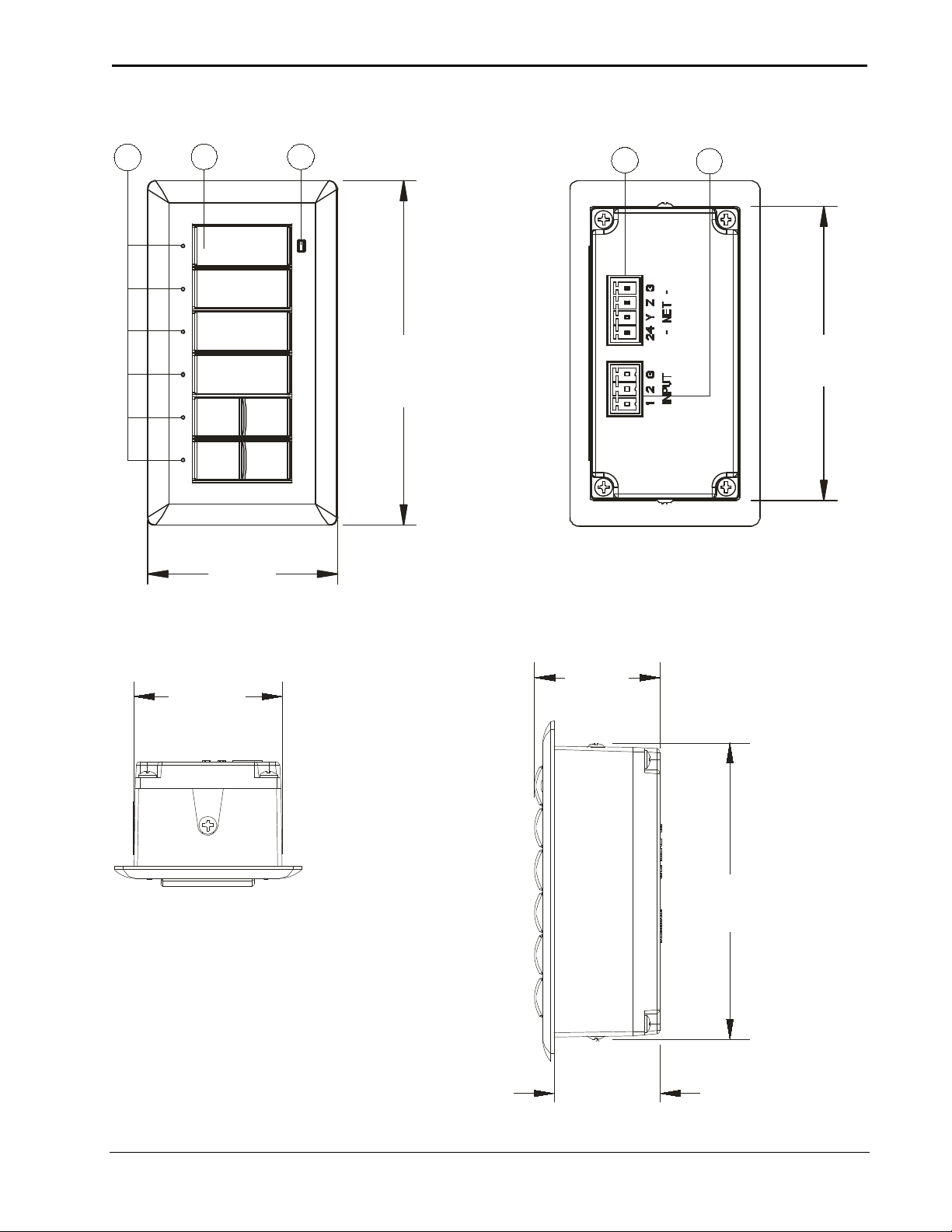
2.74 in
(70 mm)
1.76 in
(45 mm)
3.21 in
(82 mm)
2.80 in
(72 mm)
1.39 in
(36 mm)
0.99 in
(26 mm
)
1.18
in
(30 mm)
C2N-CBF-P Overal l Dimensions (Front and Rear Views)
C2N-CBF-P Overal l Dimensions (Top and Si de Views)
Operations & Installation Guide - DOC. 7063E Cameo Keypads • 15
Page 20

Cameo Keypads Crestron C2N-CBD/CBF/CBV
C2N-CBV-P Overall Dimensions (Top, Fron t an d Side Views)
16 • Cameo Keypads Operations & Installation Guide - DOC. 7063E
Page 21

Crestron C2N-CBD/CBF/CBV Cameo Keypads
#
CONNECTORS1,
INDICATORS
DESCRIPTION
1
LED Indicators
feedback LEDs
2
Buttons
Button Events - Programmable
Backlight
3
dimmable
Connectors, Controls, and Indicators
CONTROLS, AND
Feedback - (6) LEDs2 for each of
the button positions;
Programmable, auto-dimmable3,
adjustable intensity, 10 blinking
patterns
Bar Graph - (1) 6-segment bar
graph display utilizing the six
Keypad Buttons - Configurable
for two to eight single action push
buttons
for normal, tap, double-tap, and
hold
Button Caps (All except
C2N-CBV)
4, 5
- Includes (2) large,
(3) medium, (5) small, and (2 pair)
of split small button caps.
6,7
Button Caps (C2N-CBV only)4 -
Includes (5) small, and (1 pair) split
small button caps.
6,7
Medium and
large sizes sold separately.
- White LED backlight
for button engraving, software
adjustable intensity, auto-
3 Light Sensor3 Photosensor to control auto-
Operations & Installation Guide - DOC. 7063E Cameo Keypads • 17
(Continued on following page)
dimming function
Configurable to report ambient light
level to control system
Page 22

Cameo Keypads Crestron C2N-CBD/CBF/CBV
#
CONNECTORS1,
INDICATORS
DESCRIPTION
24
Y Z
G
G
1 2 G
Occupancy
Sensor
Contact Closure
Input
Doorbell
Switch
1 2
G
Connectors, Controls, and Indicators (Continued)
CONTROLS, AND
4 NET
5 INPUT (1–2)3
(1) 4-pin 3.5 mm detachable
terminal block;
Cresnet slave port, connects to
Cresnet control network
24: Power (24 volts dc)
Y: Data
Z: Data
: Ground
(1) 3-pin 3.5 mm detachable
terminal block comprising two
digital input/output or analog
input ports (referenced to GND);
Digital Input: Rated for 0–24 volts
dc, input impedance 200 k Ω,
logic threshold 1.24 volts dc;
Analog Input: Rated for 0–10
volts dc, protected to 24 volts dc
maximum, input impedance
200 k Ω;
Programmable 5 volts, 2 k Ω
pull-up resistor per pin
18 • Cameo Keypads Operations & Installation Guide - DOC. 7063E
1. Interface connectors for the NET and INPUT ports are provided with the unit.
2. Feedback LEDs are green on the C2N-CBD-E, and white on the C2N-CBD-P,
C2N-CBD-P-KP, C2N-CBF-P, and C2N-CBV-P.
3. All except C2N-CBD-E.
4. Button caps are backlit on all except C2N-CBD-E.
5. The C2N-CBD-P-KP does not include additional button caps. The keypad is
supplied with its own buttons depending on the model specified in the order.
6. Split small buttons may be installed in the bottom two positions only.
7. All buttons blank. Custom backlit engraved button caps available separately.
Page 23

Crestron C2N-CBD/CBF/CBV Cameo Keypads
30).
Setup
Network Wiring
When wirin g the Cresnet network, consider the following:
• Use Crestron Certified Wire.
• Use Crestron power supplies for Crestron equipment.
• Provide sufficient power to the system.
CAUTION: Insufficient pow er can lead to unpredictable results
or damage to the equipment. Use the C restron P ower Calculator to
help calcul ate how much power is nee ded for the system
(
www.crestron.com/calculators).
For Cresnet networks with 20 or more devices, u se a Cresnet
Hub/Repea ter (CNXHUB) to maintain signal q uality.
For more details, refer to “Check Network Wiring” on page 34.
Identity Code
The Net ID of the C2N-CBD/CBF/CBV has been factory set to 03. The
Net IDs of m ultiple C2N-CBD/CBF/CBV devices in the same system
must be uniq ue. Net IDs are changed from a personal computer (PC) via
Crestron Toolbox™ (refer to “Establishing C ommunication” on page
When settin g the Net ID, consider the following:
• The Net ID of each unit m ust match an ID code specified in the
Crestron Studio™ or SIMPL Windows program.
• Each network device must have a unique Net ID.
For more details, refer to the Crestron Toolbox help fi le.
NOTE: The latest software can be downloaded from the Crestron Web
site (www.crestron.com/software).
Assembly and Installation
Assembly of the keypad consists of placing the button caps in position on
the rear housing assembly and attaching the bezel.
Operations & Installation Guide - DOC. 7063E Cameo Keypads • 19
Page 24
Cameo Keypads Crestron C2N-CBD/CBF/CBV
DESCRIPTION
USE
QTY
Bezel
Bezel assembly
1
3-pin female mini
The cable is to be used to
1
#2-28 x 3/16”
keypad rear housing assembly
#6-32 x 3/4"
keypad to an electrical box
Double-row button
Switch cover for two switches
3
Installatio n con s ists o f conne ct in g the u ni t to the Cres ne t sy stem,
connecting the co nta c t clos ure i nput c ab le, if any , and then in ser t in g the
unit into the mounting surface or attaching it to an electrical box,
depending on the keypad configuration.
The following items are required for all installations:
• Cresnet network cable (sold separately)
• No. 2 Phillips screwdriver (not supplied)
NOTE: Verify that there is sufficient Cresnet power to support all
Cresnet devices.
Standard Mounting Installation
Standard m ount Cameo keypads are supplied part ially assembled along
with severa l items as listed in the following table.
Supplied Hardware for the C2N-CBD-E, C2N-CBD-P, and
C2N-CBD-P-KP
4-pin female mini
network connector
network connector
(C2N-CBD-P and
C2N-CBD-P-KP only)
Screws,
Screws,
Single-row button
cap
Used to connect Cresnet
network cable to the keypad
connect contact closure to the
keypad
Used to attach the bezel to the
Used to attach the assembled
Switch cover for a single row
switch
1
2
2
5
cap
Triple-row button cap Switch cover for three switches
Split-row button caps
(pair)
20 • Cameo Keypads Operations & Installation Guide - DOC. 7063E
that function as one
that function as one
Switch cover for a single row of
two switches
2
2
Page 25

Crestron C2N-CBD/CBF/CBV Cameo Keypads
LED
Holes
LEDs
Light
Sensor*
Screws (2)
#2-28 x 3/16"
Bezel
NOTE: The C2N-CBD-P-KP comes pre-assembled with either On and
Off buttons or SCENE 1–4, up, down, and Off buttons. The devices do
not come with extra button caps.
Assemble the keypad a s described in the follow ing steps. Refer to the
accompanying illustration.
1. Arrange the bu tt o n caps in po s it ion on th e r ear hous in g assembly
according to the pr og ra m plan.
2. Carefully position the bezel o ver the button caps on the rear
housing assembly.
3. Install and tighten the two supplied #2-28 x 3/16” screws.
4. Press each button and release to ensure that the button caps move
freely.
Assembling the Keypad (C2N-CBD Shown)
* All except C2N-CBD-E.
Operations & Installation Guide - DOC. 7063E Cameo Keypads • 21
Page 26

Cameo Keypads Crestron C2N-CBD/CBF/CBV
After the Cresnet network wiring has been installed and verified, use the
following pr oce dur e to install the keypad in a standard 1-gang electrical
box.
1. Turn Cresnet system power off.
2. Using the supplied 4-pin connector, connect the Cresnet cable to
the NET port of the key pad
3. (Optional) Using the supplied 3-pin connector (all except
C2N-CBD-E), connect the contact closure input cable to the
INPUT port of the keypad.
4. Make sure the keypad is oriented properly (note the lo cat i on of the
LEDs and light sensor), place it in the electrical box, an d attach it
using the inclu de d #6-32 x 3/ 4" scr ew s.
CAUTION: Excess wire pinched between the keypad and
electrica l box could short out. Make sure all excess wire is
completely inside the electrical box and not between the box and
the keypad.
22 • Cameo Keypads Operations & Installation Guide - DOC. 7063E
Page 27

Crestron C2N-CBD/CBF/CBV Cameo Keypads
Screws (2)
#6-32 x 3/4”
Mounting th e Keypad
5. Attach the desired decorator style faceplate (not supplied).
6. Turn Cresnet system power on.
Operations & Installation Guide - DOC. 7063E Cameo Keypads • 23
Page 28

Cameo Keypads Crestron C2N-CBD/CBF/CBV
DESCRIPTION
USE
QTY
Bezel
Bezel assembly
1
3-pin female mini
The cable is to be used to
1
#2-28 x 3/16”
in the mounting surface
Double-row button
Switch cover for two switches
3
Flush Mounting Ins tallation
The flush mount Cameo keypad is supplied partially assembled along
with several items as listed in the follow ing table.
Supplied Hardware for the C2N-CBF-P
4-pin female mini
network connector
network connector
Screws, Zinc, Phillips
pan head,
Template Used to mark correct hole size
Single-row button
cap
cap
Triple-row button cap Switch cover for three switches
Split-row button caps
(pair)
Used to connect Cresnet
network cable to the keypad
connect contact closure to the
keypad
Used to attach the bezel to the
keypad rear housing assembly
Switch cover for a single row
switch
that function as one
that function as one
Switch cover for a single row of
two switches
1
2
1
5
2
2
Assemble the keypad a s described in the follow ing steps. Refer to the
accompanying illustration.
1. Arrange the bu tt o n caps in po s it ion on th e r ear hous in g assembly
according to the pr og ra m plan.
2. Carefully position the bezel over the button caps on the rear
housing assembly.
24 • Cameo Keypads Operations & Installation Guide - DOC. 7063E
Page 29

Crestron C2N-CBD/CBF/CBV Cameo Keypads
LED
Holes
LEDs
Light
Sensor
Screws (2)
#2-28 x 3/16”
Bezel
Assembling the Keypad (C2N-CBF Shown)
3. Install and tighten the two supplied #2-28 x 3/16” screws.
4. Press each button an d release to ensure that the button caps move
freely.
5. Use the included template to prepare the hole in the mounting
surface. (Refer to “Appendix: Template for Flus h Mount Hole” on
page 36 for an il lustration of the tem plate.)
NOTE: Be very careful when cutting the hole. There are no
adjustments for alignment with the spring clamp. The optional
MMK-G1-CBF-T Mud Ring Mount Kit for Cameo Flush Mount
Keypads (sold separately) may be used if the cutout in the
mounting surface is too large for the keypad.
Operations & Installation Guide - DOC. 7063E Cameo Keypads • 25
Page 30

Cameo Keypads Crestron C2N-CBD/CBF/CBV
After the Cresnet network wiring has been installed and ve rified, use the
following pr oce dur e to install the keypad in the prepared hole.
1. Turn Cresnet system power off.
2. Connect the Cr es ne t ca ble to the keypad’s NET port using the
supplied mating connector.
3. Connect the contact closure input cable (if any) to the keypad’s
INPUT port using the supplied mating connector.
4. Make sure the keypad is oriented properly (note the lo cat i on of the
LEDs and light sensor), and insert the keypad in the hole. The
natural action of the spring clamp holds the keypad in position
(Refer to the illus tra ti on th at f oll ow s th is st ep.)
Mounting th e C2N-CBF Keypad
5. Turn Cresnet system power on.
6. If the keypad needs to be removed f rom the mounting surface, use
a small flat blade screwdriver to carefully pry the keypad away
from the mounting surface. Without damaging the keypad or
mounting surface, gently remove the keypad.
26 • Cameo Keypads Operations & Installation Guide - DOC. 7063E
Page 31

Crestron C2N-CBD/CBF/CBV Cameo Keypads
DESCRIPTION
USE
QTY
Vimar Style Bezel
Bezel assembly
1
3-pin female mini
The cable is to be used to
1
#2-28 x 3/16”
cap
switch
Vimar Style Electrical Box Mounting Installation
The Vimar mount Cameo keypad is su pplied partially assembled along
with severa l items as listed in the following table.
Supplied Hardware for the C2N-CBV-P
4-pin female mini
network connector
network connector
Screws, Zinc, Phillips
pan head,
Single-row button
Split-row button caps
(pair)
Assemble the keypad a s described in the follow ing steps. Refer to the
accompanying illustration.
1. Arrange the button caps in position on the rea r hou sin g
assembly according to the program plan.
Used to connect Cresnet
network cable to the keypad
connect contact closure to the
keypad
Used to attach the bezel to the
keypad rear housing assembly
Switch cover for a single row
Switch cover for a single row of
two switches
1
2
5
1
Operations & Installation Guide - DOC. 7063E Cameo Keypads • 27
2. Carefully position the bezel o ver the button caps on the rear
housing assembly.
3. Install and tighten the two supplied #2-28 x 3/16” screws.
Page 32

Cameo Keypads Crestron C2N-CBD/CBF/CBV
Assembling the Keypad (C2N-CBV Shown)
4. Press each button an d release to ensure that the button caps
move freely.
After the Cresnet network wiring has been installed and ve rified, use the
following pr oce dur e to install the keypad in Vimar style electrical box.
1. Turn Cresnet system power off.
2. Connect the Cr es ne t ca ble to the keypad’s NET port using the
supplied mating connector.
3. Connect the contact closure input cable (if any) to the keypad’s
INPUT port using the supplied mating connector.
4. Make sure the keypad is oriented properly (note the lo cation of
the LEDs and light sensor) and then place it in the Vimar style
electrica l box. The keypad snaps int o pla ce .
CAUTION: Excess wire pinched between the keypad and
electrica l box could short out. Make sure all excess wire is
completely inside the electrical box and not between the b ox and
the keypad.
28 • Cameo Keypads Operations & Installation Guide - DOC. 7063E
Page 33

Crestron C2N-CBD/CBF/CBV Cameo Keypads
Mounting th e Keypad
5. Turn Cresnet system power on.
Operations & Installation Guide - DOC. 7063E Cameo Keypads • 29
Page 34

Cameo Keypads Crestron C2N-CBD/CBF/CBV
Uploading and Upgrading
Crestron re commends u sing the latest programming software and tha t
each device contains the latest f irmware to take advantage of the m ost
recently released features. However, before attempting to upload or
upgrade it is necessary to establish comm unication. Once communic ation
has been established, files (for example, programs or firmware) can be
transferred to the control system and device. Finally, program checks can
be performed (such as changing the device ID) to ensure pr oper
functioning.
NOTE: Crestron software and any files on the Web site are for
Authorized C restron dealers and Crestron Service Providers (CSPs) only.
New users may be required to regis ter to obtain access to certain areas of
the site (including the FTP site).
Establishing Co m m un ic ation
Use Crestron Toolbox for communicating with the
C2N-CBD/CBF/CBV; refer to the Crestron Toolbox help file for details.
There is a single method of communication: in direct communication.
Indirect Communication
The C2N-CBD/CBF/CBV connects to control system via Cresnet.
1. Click To ols | System Info.
2. Click the
3. For Connection Type, select Cresnet ID. In the Through
drop-down menu, select the control system.
icon.
4. Click OK. Communications are confirmed when the device
informatio n is disp la yed.
30 • Cameo Keypads Operations & Installation Guide - DOC. 7063E
Page 35

Crestron C2N-CBD/CBF/CBV Cameo Keypads
Windows
including the FTP site.)
Programs and Firmware
Program or firmware files may be distributed from programmers to
installers or from Crestron to dealers. Firmware upgrades are available
from the Crestron Web site as new features are developed after product
releases. One has the op tion to upload programs via the programming
software or to uplo ad and upgr a de vi a the Cre stron Toolbo x. For de tails
on uploading and upgrading, refer to the Crestron Studio help file, the
SIMPL Windows help file, or the Crestron Toolbox help file.
Crestron
Studio /
SIMPL
Firmware
If a Crestron Studio (or SIMPL Windows) program is provided, it can be
uploaded to the co ntr ol system using Crestron Studio (or SIMPL
Windows) or Crestron Toolbox.
Check the Cr estron Web site to find the latest firmware. (New users may
be required to register to obtain ac cess to certain areas of the site,
Upgrade C2N-CBD/CBF/CBV firmware via Crestron Toolbox.
1. Establi sh communication with the C2N-CBD/CBF/CBV and
display the “System Info” window.
2. Select Functions | Firmware… to upgrade the
C2N-CBD/CBF/CBV firmware.
Program Checks
Using Crestron Toolbox, display the network device tree (Tools |
Network Device Tree) to show all network devic es connected to the
control sy stem. Right-click on the C2N-CBD/CBF/CBV to display
actions that can be pe rfor med on the C2N-CBD/CBF/CBV.
Operations & Installation Guide - DOC. 7063E Cameo Keypads • 31
Page 36

Cameo Keypads Crestron C2N-CBD/CBF/CBV
Ambient Light Sensor Operation
The C2N-CBD-P, C2N-CBD-P-KP, C2N-CBF-P, and C2N-CBV-P
keypads have an ambient light sensor that can be used to aut omatically
configure the ba c kli g ht to op erate in either Day mode or Night mode.
Backlight ope ration is based on ambient light le vel and a programmed
threshold. Presets based on the keypad color set the optimum backlight
level for Day mode and Night mode.
When using presets, the following occurs:
• For light color ed keypads with dark engraving, the backlight tu rns
on dim when in Night mode and off when in Day mode.
• For dark colored keypads, the backlight turns on dim when in
Night mode and on brig ht when in Day mode.
NOTE: Backlight levels can also be set manually.
The indicator LEDs automatically adjust their brightness base d on
ambient light, going bright when the keypad is well lit and going dim
when the room is dark.
When two or more keypads ar e to be in sta l l ed side by side, ensure that
the backlights on all units are in sync. To do this, there are signals
available o n the programming symbol to allow one unit to act as the
master bac klight controller, an d the rest as slaves.
Refer to the Crestron Stu d io or SIMPL Windows help file for more
information.
32 • Cameo Keypads Operations & Installation Guide - DOC. 7063E
Page 37

Crestron C2N-CBD/CBF/CBV Cameo Keypads
TROUBLE
POSSIBLE
CAUSE(S)
CORRECTIVE
ACTION
The keypad does
The wrong power
Use a Crestron power
The unit is not
Verify the cable
There is a loose
Verify the cable
proper Net ID.
Problem Solving
Troubleshooting
The following table provides corrective action for possible trouble
situations. If further assistance is required, please contact a Crestron
customer service representative.
C2N-CBD/CBF/CBV Troubleshooting
not function.
The keypad does
not function. All
six feedback
LEDs are on low.
Keypad does not
function, or does
not function as
expected.
However, it
reports on
Cresnet at the
supply is being
used.
receiving power, or
is receiving
insufficient power.
connection in the
network.
Improper Net ID
used.
The unit is not
programmed
correctly.
supply.
plugged into the NET
port is secure. Verify
that the power supply
is correct.
plugged into the NET
port is secure.
Verify the
C2N-CBD/CBF/CBV
Net ID matches the
Net ID in the software
program.
Use SIMPL Debugger
to check the behavior
when buttons are
pressed. Revise and
reload the program as
needed to correct the
behavior.
Operations & Installation Guide - DOC. 7063E Cameo Keypads • 33
Page 38
Cameo Keypads Crestron C2N-CBD/CBF/CBV
deficiencies because of using improper wire.
Cresnet uni ts are to be daisy chaine d on the run, the Cresnet power usage
L = Length of run (
or chain) in feet
R
= 6 Ohms (Crestron Certified Wire
: 18 AWG (0
.75 mm ))
or 1.6 Ohms
(Cresnet HP: 12 AWG
(4 mm ))
P = Cresnet power usage of entire run (or chain
)
2
2
L <
40,000
R x P
Where:
Crestron Ce rtified Wire and drawing 20 watts should not have a length of
Check Network Wi r ing
Use the
Right Wire
To ensure optimum performance ove r the full r ange of the installation
topology, use Crestron Certified Wire only. Failure to do so may incur
additional charges if support is re quired to identify performance
Calculate
Power
CAUTION: Use only Crestro n power supplies for Crestron equipment.
Failure to do so could cause equipment damage or void the Crestron
warranty.
CAUTION: Provide sufficient power to the system. Insufficient power
can lead to unpredictable results or damage to the equipment. Use the
Crestron Power Calculator to help c alculate how much powe r is needed
for the system (
www.crestron.com/calculators).
When calcu lating the length of wire for a particular Cresnet run, the wire
gauge and the Cresnet power usage of each network unit to be connected
must be take n into consideration. Use Crestron Certified Wire only. If
of each network unit to be daisy c hained must be added together to
determine the Cresnet power usage of the entire chain. If the unit is
home-run from a Crestron system power supply network port, the
Cresnet pow er usage of that unit is the Cresnet power usage of the entire
run. The wire gauge and the Cresnet power usa ge of the run sh oul d be
used in the followi n g equat i on to ca lc ula t e the cab le le ng th va lu e on the
equation’s le ft si de.
Cable Length Equation
Make sure the cable length value is less than the value calculated on the
right side of the equation. For example, a Cresnet run using 18 AWG
run more than 333 feet (101 meters) . If Cresnet HP is used for the sam e
run, its len gth could extend to 1250 feet (381 meters).
NOTE: All certified Crestron Cre snet wiring must consi st of two
twisted pairs. One twisted pair is the 24 and G pair and the other twisted
pair is the Y and Z pair.
34 • Cameo Keypads Operations & Installation Guide - DOC. 7063E
Page 39

Crestron C2N-CBD/CBF/CBV Cameo Keypads
procedure f or the other three conductors.
combined total length of Cresnet cable exceeds 3000 feet (914 meters).
DOCUMENT TITLE
Strip and Tin
Wire
Add Hubs
When daisy chaining Cresnet unit s, strip the ends of the wires carefully
to avoid nic king the conductors. Twist together the ends of the wires that
share a pin o n the network connector and tin the twisted connection.
Apply solder only to the ends of the twisted wires. Avoid tin ning too far
up the wires or the end becomes brittle . Insert the tinned connection into
the Cresnet connector and tighten the retaining screw. Repeat the
Use of a Cres net Hub/Repeater (CNX HUB) is advised wheneve r the
number of Cr esnet devices on a network exceeds 20 or when the
Reference Documents
All docum ents in this guide are available at www.crestron.com/manuals.
List of Related Reference Documents
2-Series Control Systems Reference Guide
Further Inquiries
To locate spe cific information or resolve que stions after reviewing this
guide, contact Crestron's True Bl ue Support at 1-888-CRESTRON
[1-888-273-7876] or, for assistance within a particular geographic re gion,
refer to the listing of Cr es tr on wo rl dw ide of fic e s at
(
www.crestron.com/offices.
To post a question about Crestron products, log onto Crestron’s Online
Help at
user account to fully benefit from all available features.
www.crestron.com/onlinehelp. First-time users must est ablish a
Future Updates
As Crestron improves functions, adds new features, and extends the
capabilities of the C2N-CBD-P / C2N-CBD-P-KP / C2N-CBD-E /
C2N-CBF-P / C2N-CBV-P keypads, addit ional information m ay be made
available as manual updates. These updates are solely electronic and
serve as intermediary supplements prior to the release of a complete
technical d ocumentation revision.
Check the Cr estron Web site period ically for manual update availability
and its rele vance. Updates are ide ntified as an “Addendum” in the
Download c olumn.
Operations & Installation Guide - DOC. 7063E Cameo Keypads • 35
Page 40

Cameo Keypads Crestron C2N-CBD/CBF/CBV
Appendix: Template for Flush Mount Hole
The figure o n the following page (not to scale) illustrates the supplie d
template used to prepare the hole in the wall or other mounting surface
for the flus h mount Cameo keypad.
NOTE: Use only the original template to pre par e th e hol e, not a
photocopy. Photocopies usually alter the size of the image slightly, which
would make the hole the wrong size.
Be careful when cutting the hole; the spring clamp on the keypad does
not have provision for positioning adjustment. Also, ensure that there is a
sufficient clearance area behind the mounting surface as shown on the
template.
36 • Cameo Keypads Operations & Installation Guide - DOC. 7063E
Page 41

Crestron C2N-CBD/CBF/CBV Cameo Keypads
5 3/8 in
(137 mm)
3 1 /4 in
(83 mm)
2 7 /8 in
(73 mm)
1 1 /2 in
1 3 /4 in
(45 mm)
3 5 /16 in
(39 mm)
(85 mm)
TEMPL ATE - OV40096
FOR C2N-CBF
THIS PIECE IS FOR CENTER LINE
REFERENCE ONLY.
DO NOT USE THIS PIECE
AS A CUTTING TEMP L A TE
CUT AL
ONG THIS LINE
CUT ALONG THIS LI
NE
CLEARANCE AREA
FOR BEZEL
Cutout Template (Not to Scale)
Operations & Installation Guide - DOC. 7063E Cameo Keypads • 37
Page 42

Cameo Keypads Crestron C2N-CBD/CBF/CBV
Return and Warranty Policies
Merchandise Returns / Repair Service
1. No merchandise may be returned for credit, exchange or service without prior authorization from
Crestron. To obtain warranty service for Crestron products, contact an authorized Crestron dealer.
Only authorized Crestron dealers may contact the factory and request an RMA (Return
Merchandise Authorization) number. Enclose a note specifying the nature of the problem, name
and phone number of contact person, RMA number and return address.
2. Products may be returned for credit, exchange or service with a Crestron Return Merchandise
Authorization (RMA) number. Authorized returns must be shipped freight prepaid to Crestron,
6 Volvo Drive, Rockleigh, N.J. or its authorized subsidiaries, with RMA number clearly marked
on the outside of all cartons. Shipment s arriving freight collect or without an RM A numb e r shall
be subject to refusal. Crestron reserves the right in its sole and absolute discretion to charge a 15%
restocking fee plus shipping costs on any products returned with an RMA.
3. Return freight charges following repair of items under warranty shall be paid by Crestron,
shipping by standard ground carrier. In the event repairs are found to be non-warranty, return
freight costs shall be paid by the purchaser.
Crestron Limited Warranty
Crestron Electronics, Inc. warrants its products to be free from manufacturing defects in materials and
workmanship under normal use for a period of three (3) years from the date of purchase from Crestron,
with the following exceptions: disk drives and any other moving or rotating mechanical parts, pan/tilt
heads, and power supplies are covered for a period of one (1) year; touch screen display and overlay
components are covered for 90 days; batteries and incandescent lamps are not covered.
This warranty extends to products purchased directly from Crestron or an authorized Crestron dealer.
Purchasers should inquire of the dealer regarding the nature and extent of the dealer's warranty, if any.
Crestron shall not be liable to honor the terms of this warranty if the product has been used in any
application other than that for whic h it was intended or if it has been subjecte d to misuse, accidental
damage, modification, or improper installation procedures. Furthermore, this warranty does not cover any
product that has had the serial number altered, defaced, or removed.
This warranty shall be the sole and exclusive remedy to the original purchaser. In no event shall Crestron
be liable for incidental or consequential damages of any kind (property or economic damages inclusive)
arising from the sale or use of this equipment. Crestron is not liable for any claim made by a third party or
made by the purchaser for a third party.
Crestron shall, at its option, repair or replace any product found defective, without charge for parts or labor.
Repaired or replaced equipment and parts supplied under this warranty shall be covered only by the
unexpired portion of the warranty.
Except as expressly set forth in this warranty, Crestron makes no other warranties, expressed or implied,
nor authorizes any other party to offer any warranty, including any implied warranties of merchantability or
fitness for a particular purpose. Any implied warranties that may be imposed by law are limited to the terms
of this limited warranty. This warranty statement supersedes all previous warranties.
38 • Cameo Keypads Operations & Installation Guide - DOC. 7063E
Page 43

Crestron C2N-CBD/C2N-CBF Series Cameo Keypads
This page is intentionally left blank. This page is intentionally left blank.
Operations & Installation Guide - DOC. 7063E Cameo Keypads • 39
Page 44

Crestron Electronics, Inc. Operations & Installation Guide – DOC. 7063E
15 Volvo Drive Rockleigh, NJ 07647 (2028549)
Tel: 888.CRESTRON 07.13
Fax: 201.767.7576 Specifications subject to
www.crestron.com change without notice.
 Loading...