

Page 1

Crestron BB-1700CW
Wall Mount Back Box for STX-1700CW
Installation Guide
Page 2

This document was prepared and written by the Technical Documentation department at:
Crestron Electronics, Inc.
15 Volvo Drive
Rockleigh, NJ 07647
1-888-CRESTRON
All brand names, product names and trademarks are the property of their respective owners.
©2002 Crestron Electronics, Inc.
Page 3

Crestron BB-1700CW Wall Mount Back Box for SmarTouch
Contents
Wall Mount Back Box for STX-1700CW: BB-1700CW 1
Introduction ...............................................................................................................................1
Installation .................................................................................................................................2
Installation During Construction .................................................................................2
Installation After Construction .................................................................................... 5
Further Inquiries ........................................................................................................................9
Future Updates........................................................................................................................... 9
Appendix: Cutout Detail of Supplied Template .....................................................................10
Return and Warranty Policies.................................................................................................. 11
Merchandise Returns / Repair Service ......................................................................11
CRESTRON Limited Warranty.................................................................................11
Installation Guide – DOC. 6105 Contents • i
Page 4

Page 5

Crestron BB-1700CW Wall Mount Back Box for STX-1700CW
r
Wall Mount Back Box for
STX-1700CW: BB-1700CW
Introduction
The BB-1700CW back box is wall-mounted hardware that is used to secure the
DA-1700CW docking assembly (sold separately). When used with the BB-1700CW,
the docking assembly provides operating power, hard-wire communications with a
standard Crestron remote control system (herein referred to as the Cresnet system),
and recharges the Crestron High Performance Rechargeable Power Pack (ST-BTPN)
of a Crestron SmarTouch STX-1700CW compact color touchpanel.
Supplied Components
DESCRIPTION PART NUMBERS QUANTITY
Metal, Enclosure MTEN02571-1 1
Metal, Bracket, Mounting MTBK02577-1 1
Metal, Bracket, Mounting Support MTBK02578-1 1
Screw, 6-32, ¼ “L Steel SR06-32-0R2500-2 8
Washer, Flat, Steel, B Regula
Overlay, Template, Wall Cutout OV40053-1 1
A diagram of the two installation brackets is shown below and three views of the
back box enclosure are shown on the next page.
Installation Brackets
MOUNTING
BRACKET
WA06FL-2 8
SUPPORT
BRACKET
Installation Guide – DOC. 6105 Wall Mount Back Box for STX-1700CW: BB-1700CW • 1
Page 6

Wall Mount Back Box for STX-1700CW Crestron BB-1700CW
Back Box Enclosure Physical Views and Dimensions
5.99 in
(15.21 cm)
6.63 in
(16.85 cm)
3.75 in
(9.53 cm)
Installation
There are two different methods of installing the BB-1700CW; installation during
construction or post-construction installation. Installation during construction
describes installation into a room during construction when the room is framed and
the gypsum board has not been hung. The post-construction method is used after the
rooms are complete and gypsum board has already been hung.
Installation During Construction
This section describes installation into a room during construction when the room is
framed and the gypsum board has not been hung. Before the gypsum board is hung,
complete the following procedure in the order provided. The only tool required is a
#2 Phillips screwdriver.
NOTE: This procedure installs the left-side of the back box to the right-side of a
framing stud. If installing the back box to the left-side of a stud, reverse the
mounting bracket and the mounting support bracket but maintain the orientation of
the back box enclosure with the manual unlatching notch at the top.
1. Locate the position and height that the back box (and touchpanel) will
be installed.
2 • Wall Mount Back Box for STX-1700CW: BB-1700CW Installation Guide – DOC. 6105
Page 7
Crestron BB-1700CW Wall Mount Back Box for STX-1700CW
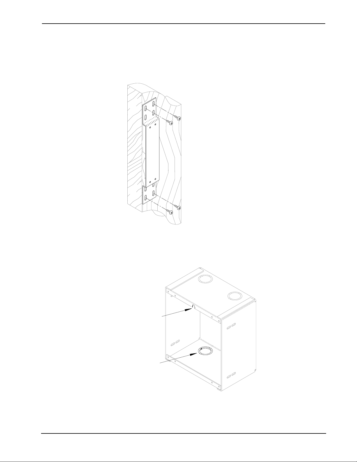
2. Refer to the diagram below. Position the mounting bracket at the edge
of the stud. Through the upper and bottom-most mounting bracket
slots and using a #2 Phillips screwdriver, secure the bracket to the stud
using four screws (not supplied).
Secure Mounting Bracket to Stud
3. Orient the back box enclosure as shown below (notch for manual
unlatching upwards) and remove an appropriate knockout for the
Cresnet wiring.
Back Box Enclosure Orientation
NOTCH
FOR MANUAL
UNLATCH TAB
ACCESS
REMOVED
KNOCKOUT
Installation Guide – DOC. 6105 Wall Mount Back Box for STX-1700CW: BB-1700CW • 3
Page 8
Wall Mount Back Box for STX-1700CW Crestron BB-1700CW
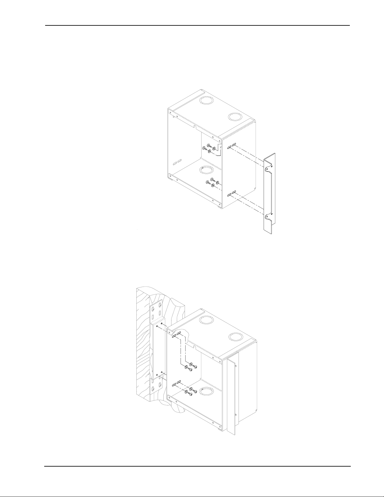
4. As shown below, loosely install four pan head screws with washers
through the inside of the enclosure into the support bracket holes.
Tighten screws only finger-tight so that final adjustments may be
made during step 7 of this procedure.
Loosely Install Support Bracket
5. As shown below, loosely install four pan head screws with washers
through the inside of the enclosure into the mounting bracket holes.
Tighten screws only finger-tight so that final adjustments may be
made during step 7 of this procedure.
Loosely Secure Enclosure to Mounting Bracket
6. Feed the Cresnet wiring through the enclosure knockout.
4 • Wall Mount Back Box for STX-1700CW: BB-1700CW Installation Guide – DOC. 6105
Page 9

Crestron BB-1700CW Wall Mount Back Box for STX-1700CW
NOTE: To be properly installed, the cutout area of the gypsum board must be cut to
within 1/8-inch (0.32 cm) of the outline of the back box enclosure.
NOTE: The next step is performed after the gypsum board is hung. The only tools
required are a ruler and a #2 Phillips screwdriver.
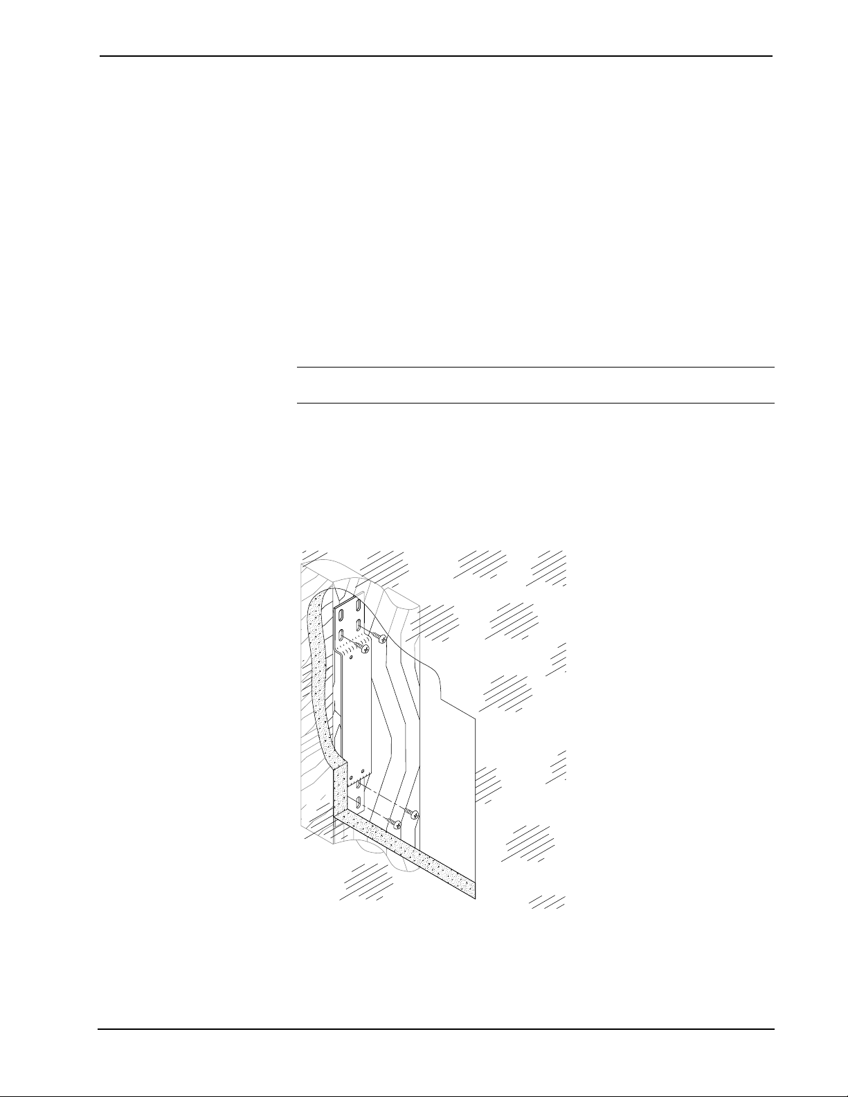
7. After the gypsum board is hung, refer to the diagram below. Using a
ruler, adjust the back box to approximately 1/16-inch (0.15 cm) inward
of the face of the gypsum board to accommodate the distance between
the back box and the front panel. Using a #2 Phillips screwdriver,
tighten the four pair of bracket screws finger-tight plus an additional
1/8-turn.
Adjust Back Box Clearance and Tighten Bracket Screws
BACK BOX
CLEARANCE
(ALL SIDES)
Installation After Construction
This section describes installation when room construction is complete and gypsum
board has been hung. Complete the following installation procedure in the order
provided. The only tools required are a stud finder (or equivalent), masking tape,
gypsum board saw (or equivalent), ruler and a #2 Phillips screwdriver.
NOTE: This procedure installs the left-side of the back box to the right-side of a
framing stud. If installing the back box to the left-side of a stud, reverse the
mounting bracket and the mounting support bracket but maintain the orientation of
the back box enclosure with the manual unlatching notch at the top.
1. Locate an area on the wall that the back box (and touchpanel) will be
installed. Make sure that the area is clear of studs, wires, or other
obstructions within the installation area.
Installation Guide – DOC. 6105 Wall Mount Back Box for STX-1700CW: BB-1700CW • 5
Page 10
Wall Mount Back Box for STX-1700CW Crestron BB-1700CW
2. Using a stud finder (or equivalent), locate the right-edge of a stud
within the installation area.
3. Align the left dashed, vertical line (labeled STUD EDGE) of the
supplied template with the right-edge of the stud. Refer to “Appendix:
Cutout Detail of Supplied Template” on page 10 for an illustrative
reference.
4. Using masking tape, fasten the supplied template to the wall; verify that
the cutout is level.
5. Using a preferred method, transfer the cutout area of the template to the
gypsum board at the location of the back box.
6. Using a gypsum board saw (or equivalent), cut the rectangular area
through the wall.
7. Remove the template and cutout area.
NOTE: To prevent the mounting bracket from falling into the wall cavity, it is
recommended to tie a safety string to the bracket when performing the next step.
8. Refer to the diagram below. Through the cut out area, position the
mounting bracket at the edge of the stud (flush with the back-side of the
gypsum board) and vertically centered in the cut-out area. Through the
mounting bracket slots closest to the center of the bracket and using a
#2 Phillips screwdriver, secure the bracket to the stud using four
screws (not supplied).
Secure Mounting Bracket to Stud
6 • Wall Mount Back Box for STX-1700CW: BB-1700CW Installation Guide – DOC. 6105
Page 11

Crestron BB-1700CW Wall Mount Back Box for STX-1700CW
9. Orient the back box enclosure as shown below (notch for manual
unlatching upwards) and remove an appropriate knockout for the
Cresnet wiring.
Back Box Enclosure Orientation
NOTCH
FOR MANUAL
UNLATCH TAB
ACCESS
REMOVED
KNOCKOUT
10. As shown below, loosely install four pan head screws with washers
through the inside of the enclosure into the support bracket holes.
Tighten screws only finger-tight so that final adjustments may be
made during step 14 of this procedure.
Loosely Install Support Bracket
11. Position the back box enclosure near the cut-out area and feed the
Cresnet wiring through the enclosure knockout.
Installation Guide – DOC. 6105 Wall Mount Back Box for STX-1700CW: BB-1700CW • 7
Page 12
Wall Mount Back Box for STX-1700CW Crestron BB-1700CW
12. Making sure that the support bracket is behind the gypsum board,
position the enclosure into the cutout area.
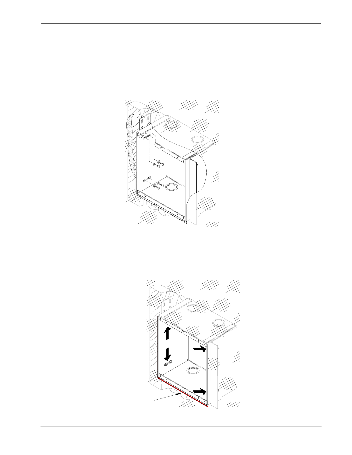
13. As shown below, loosely install four pan head screws with washers
through the inside of the enclosure into the mounting bracket holes.
Tighten screws only finger-tight so that final adjustments may be
made during the next step of this procedure.
Loosely Secure Enclosure to Mounting Bracket
14. As shown below, use a ruler to adjust the back box to approximately
1/16-inch (0.15 cm) inward of the face of the gypsum board to
accommodate the distance between the back box and the front panel.
Using a #2 Phillips screwdriver, tighten the four pair of bracket screws
finger-tight plus an additional 1/8-turn.
Adjust Back Box Clearance and Tighten Bracket Screws
BACK BOX
CLEARANCE
(ALL SIDES)
8 • Wall Mount Back Box for STX-1700CW: BB-1700CW Installation Guide – DOC. 6105
Page 13

Crestron BB-1700CW Wall Mount Back Box for STX-1700CW
Further Inquiries
If after reviewing this Installation Guide for the BB-1700CW, you cannot locate
specific information or have questions, please take advantage of Crestron's award
winning customer service team by calling:
• In the US and Canada, call Crestron’s corporate headquarters at
1-888-CRESTRON [1-888-273-7876].
• In Europe, call Crestron International at +32-15-50-99-50.
• In Asia, call Crestron Asia at +852-2341-2016.
• In Latin America, call Crestron Latin America at +5255-5093-2160.
• In Australia and New Zealand, call Crestron Control Solutions at
+61-2-9737-8203.
Future Updates
As Crestron adds improvements to the BB-1700CW, additional information may be
made available as manual updates. These updates are solely electronic and serve as
intermediary supplements prior to the release of a complete technical documentation
revision.
Check the Crestron website (www.crestron.com) periodically for manual update
availability and its relevance. Updates are available from the Download | Product
Manuals section and are identified as an “Addendum” in the Download column.
Installation Guide – DOC. 6105 Wall Mount Back Box for STX-1700CW: BB-1700CW • 9
Page 14

Wall Mount Back Box for STX-1700CW Crestron BB-1700CW
A
A
A
Appendix: Cutout Detail of Supplied Template
Crestron recommends that the template supplied with the BB-1700CW be used to
avoid any error. However, if the template becomes lost or unusable, the dimensions
of the cutout area are shown below.
NOTE: Depending on the specific installation, the BB-1700CW may be installed
either on the left or right side of a stud.
6.14 in (15.61 cm)
PPROXIMATELY
6-9/64 in
TEMPLATE - OV40053-1
CUT ALONG
LINE
STUD EDGE
DISTANCE FROM STUD
0.30 in (0.76 cm),
PPROXIMATELY 19/64 in
6.78 in (17.23 cm)
PPROXIMATELY
6-25/32 in
10 • Wall Mount Back Box for STX-1700CW: BB-1700CW Installation Guide – DOC. 6105
Page 15

Crestron BB-1700CW Wall Mount Back Box for STX-1700CW
Return and Warranty Policies
Merchandise Returns / Repair Service
1. No merchandise may be returned for credit, exchange, or service without prior
authorization from CRESTRON. To obtain warranty service for CRESTRON products,
contact the factory and request an RMA (Return Merchandise Authorization) number.
Enclose a note specifying the nature of the problem, name and phone number of contact
person, RMA number, and return address.
2. Products may be returned for credit, exchange, or service with a CRESTRON Return
Merchandise Authorization (RMA) number. Authorized returns must be shipped freight
prepaid to CRESTRON, 6 Volvo Drive, Rockleigh, N.J., or its authorized subsidiaries,
with RMA number clearly marked on the outside of all cartons. Shipments arriving
freight collect or without an RMA number shall be subject to refusal. CRESTRON
reserves the right in its sole and absolute discretion to charge a 15% restocking fee, plus
shipping costs, on any products returned with an RMA.
3. Return freight charges following repair of items under warranty shall be paid by
CRESTRON, shipping by standard ground carrier. In the event repairs are found to be
non-warranty, return freight costs shall be paid by the purchaser.
CRESTRON Limited Warranty
CRESTRON ELECTRONICS, Inc. warrants its products to be free from manufacturing
defects in materials and workmanship under normal use for a period of three (3) years from
the date of purchase from CRESTRON, with the following exceptions: disk drives and any
other moving or rotating mechanical parts, pan/tilt heads and power supplies are covered for
a period of one (1) year; touchscreen display and overlay components are covered for 90
days; batteries and incandescent lamps are not covered.
This warranty extends to products purchased directly from CRESTRON or an authorized
CRESTRON dealer. Purchasers should inquire of the dealer regarding the nature and extent
of the dealer's warranty, if any.
CRESTRON shall not be liable to honor the terms of this warranty if the product has been
used in any application other than that for which it was intended, or if it has been subjected
to misuse, accidental damage, modification, or improper installation procedures.
Furthermore, this warranty does not cover any product that has had the serial number altered,
defaced, or removed.
This warranty shall be the sole and exclusive remedy to the original purchaser. In no event
shall CRESTRON be liable for incidental or consequential damages of any kind (property or
economic damages inclusive) arising from the sale or use of this equipment. CRESTRON is
not liable for any claim made by a third party or made by the purchaser for a third party.
CRESTRON shall, at its option, repair or replace any product found defective, without
charge for parts or labor. Repaired or replaced equipment and parts supplied under this
warranty shall be covered only by the unexpired portion of the warranty.
Except as expressly set forth in this warranty, CRESTRON makes no other warranties,
expressed or implied, nor authorizes any other party to offer any warranty, including any
implied warranties of merchantability or fitness for a particular purpose. Any implied
warranties that may be imposed by law are limited to the terms of this limited warranty. This
warranty statement supercedes all previous warranties.
Trademark Information
All brand names, product names, and trademarks are the sole property of their respective owners. Windows is a
registered trademark of Microsoft Corporation. Windows95/98/Me/XP and WindowsNT/2000 are trademarks of
Microsoft Corporation.
Installation Guide – DOC. 6105 Wall Mount Back Box for STX-1700CW: BB-1700CW • 11
Page 16

Crestron Electronics, Inc. Installation Guide – DOC. 6105
15 Volvo Drive Rockleigh, NJ 07647 08.02
Tel: 888.CRESTRON
Fax: 201.767.7576 Specifications subject to
www.crestron.com change without notice.
 Loading...