

Page 1
Thank you for purchasing this Crest TV Wall Mount.
Crest prides itself on supplying quality audio visual accessories to consumers and businesses throughout Australia. If you
follow this guide carefully, we are confident this product will help maximise the enjoyment you obtain from your audio visual
equipment for many years. Please keep this guide for future reference.
TECHNICAL SUPPORT
If you have any questions regarding the
warranty, installation or use of this
product, please contact our Technical
Support Centre on 1800 812 261.
WARRANTY
This Crest TV Wall Mount carries a limited warranty of five (5) years from the date of purchase.
Crest, by this warranty, will at its discretion repair or replace the product or its components if found to be defective in
workmanship or materials. Where a warranty claim is made, Crest may require the customer at their expense to return the
product and or its components to Crest or a Crest representative for inspection.
This limited warranty covers supply of the replacement product (which may vary from the one originally purchased) only and
does not extend to, nor covers costs associated with, demounting, removal, disposal or return of the original product, or
installation of the replacement product.
This limited warranty does not cover damage or loss resulting from intentional or un-intentional misuse, tampering with,
neglect or incorrect installation or use of this product or where the product has been used for purposes other than that for
which it is designed or for supporting displays beyond the product’s capability as stated on the product’s original packaging
and in this guide. Failure to strictly comply with this installation guide may result in forfeiture of the warranty by the purchaser,
user or owner.
Any warranty claim must be accompanied by proof of purchase showing date and location of purchase.
INSTALLATION INSTRUCTIONS
IMPORTANT
1. Installation of this TV mount will be easier if two people are
involved.
2. Some images in this guide may vary slightly from the actual
components supplied.
3. Ensure this Installation Guide is completely read and
understood before attempting installation.
4. Mount MUST NOT be installed solely in plasterboard, fibre cement and similar surfaces.
5. Mount MUST be installed in sound supporting structures such as those made of timber, steel or masonry using
appropriate fasteners.
6. The supporting structure must be capable of sustaining the combined weight of the TV mount and the display
otherwise the structure must be reinforced.
7. The fasteners supplied in this hardware pack allow for fixing into timber and masonry only. If installing into a
supporting structure made of steel, appropriate fasteners must be used and sourced from an appropriate supplier.
8. Use appropriate tools and safety equipment and ensure adequate ventilation during installation.
9. If uncertain about any aspect of installation, contact Crest or an installation professional.
TOOLS REQUIRED
Drywall (Timber Frame) Installation
• Stud finder
• Spirit level
• Pencil
• Drill
• Long neck phillips head screwdriver
• 5mm diameter high speed drill bit
• Adjustable spanner
In addition, for Masonry Installation
• Drill with hammer function
• 8mm masonry drill bit
• Hammer
BFP6T This model will suit most flat panel TV sizes from 37 to 63 inches (94 to 160cm) as long as they weigh
75kg maximum and possess a maximum mounting hole pattern of 400 x 800mm (h x w)
Warranty and Installation Guide
Tilt Action Flat Panel Wall Mount
BFP6T
Page 2
Warranty and Installation Guide
Tilt Action Flat Panel Wall Mount
BFP6T
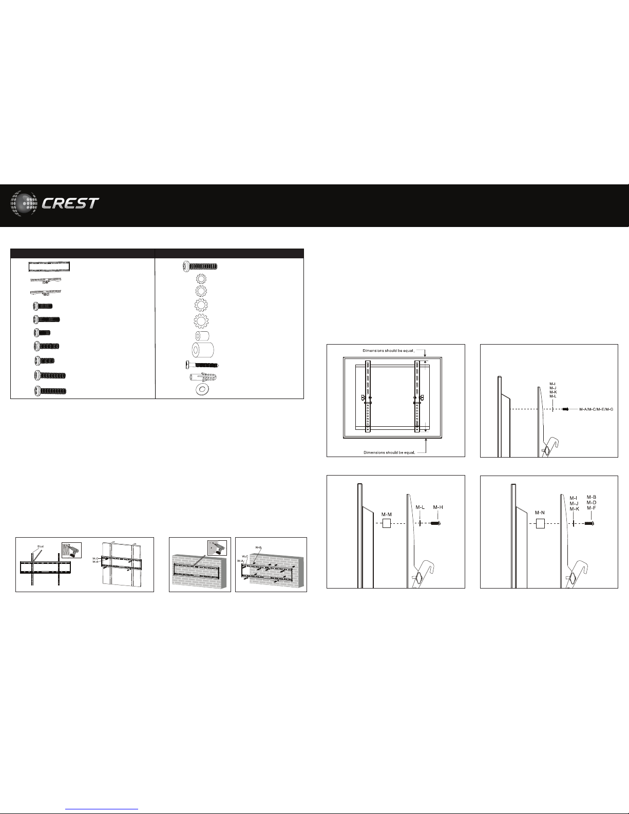
STEP 1 – ATTACH WALL MOUNT COMPONENTS TO WALL
STEP 2 – ATTACH MOUNTING ARMS TO TV
A. Installing in Drywall (Timber frame). See Figure 1.1.
1. If attaching this bracket using this method, you MUST spread
the Wall Plate across 2 wall studs. Wall studs can be 450mm or
600mm apart depending upon the position of the wall and the
state you live in. Crest will not accept any damages that may
occur is only 1 stud is used.
2. Locate centre of timber studs using stud finder.
3. Mark a minimum of four fixing holes over stud centres using wall
plate as guide (two at either end of the mount). Ensure plate
is level.
4. Predrill holes to a depth of 50mm using high speed 5mm drill bit.
If installing in hardwood, larger diameter and deeper holes may
be required.
5. Attach wall plate using lag bolts (W-A) through round washers
(W-C). Do not over tighten.
1. Lay your TV face down on something soft so as not to scratch the screen
2. Check the back of your TV to find the appropriate mounting pattern.
3. Sort through provide bolts M-A to M-H until you find the correct size that easily fits into the back of your TV and fits snugly (the bolt must
turn at least 3 full turns). Once you have selected the bolt then find the corresponding D washer. If no bolts fit you will need to go to your
local hardware to find the correct sized bolt and washer.
4. Once this has been located gently put your mounting arms (B and C) on the back of the TV so that the mounting holes are showing
through the arms (see figure 2.1).
5. If the back of your TV is curved or recessed (see figure 2.3/2.4) you will also need to use spacer M-M or M-N depending upon the amount
of space you are trying to clear. This will of course mean that you will also need to use longer screws. Remember that the bolt needs to
turn at least 3 full turns.
6. Now using the correct mounting bolt size and length through corresponding D washers to attach mounting arms to rear of TV
(see figure 2.2). To avoid damaging TV, do not over tighten bolts. (Crest is not responsible for any damage caused by screwing the bolt too
far into the back of the TV)
7. At this stage loosen the safety bolt at the bottom of each arm as shown in figure
B. Installing in Masonry. See Figures 1.2 & 1.3.
1. WARNING- ensure you have an minimum of 35mm of actual
concrete/brick thickness in the hole for the anchors. Do not drill
into mortar joints. Installer must verify that the supporting surface
will safely support the combined weight of the bracket and TV.
Crest holds no responsibility for incorrectly installed brackets.
2. Mark a minimum of four fixing holes using wall plate as guide
(two at either end of the mount) see figure 1.2. Ensure plate
is level.
3. Predrill holes to a depth of 60mm using 8mm masonry drill bit.
Clean out holes.
4. Fully insert masonry anchors (W-B). Tap in with hammer if required.
5. Attach wall plate by inserting lag bolts (W-A) through round
washers (W-C) into each masonry anchor (W-B) and tighten see
figure 1.3. Do not over tighten.
Figure 1.2 Figure 1.3Figure 1.1
Figure 2.4Figure 2.3
Figure 2.2Figure 2.1
A
B
C
M-A
M-B
M-C
M-D
M-E
M-F
M-G
Wall Plate
Left Adaptor Bracket
Right Adaptor Bracket
M4 x 12mm
M4 x 30mm
M5 x 12mm
M5 x 30mm
M6 x 12mm
M6 x 35mm
M8 x 16mm
1
1
1
4
4
4
4
4
4
4
Item Description Qty
M-H
M-I
M-J
M-K
M-L
M-M
M-N
W-A
W-B
W-C
M8 x 40mm
D4 Washer
D5 Washer
D6 Washer
D8 Washer
ø14 x ø6 x 10mm
ø5 x ø8 x 15mm
ST8 x 63mm
Concrete Anchor
D8 Washer
4
4
4
4
4
4
4
6
6
6
Item Description Qty
HARDWARE KIT CONTENTS
Page 3

Warranty and Installation Guide
Tilt Action Flat Panel Wall Mount
203mm
Min 80. Max 806mm
864mm
40mm
Min 58. Max 410mm
0º
-10º
w
w
w
.
c
r
e
s
t
.
c
o
m
.
a
u
t
e
c
h
n
i
c
a
l
s
u
p
p
o
r
t
1800 812 261
165 South Pine Rd
PO Box 5658
Brendale
Qld 4500
STEP 3 – HOOK ARMS OVER MOUNTING PLATE
1. With help of another person, carefully lift TV and hook arms over the mounting plate (see figure 3.1).
2. Tighten safety screws at bottom of arms with long neck Phillips head screw driver. This will help ensure that your TV does not fall off your
wall mount during use.
3. Once this is done you may now adjust the angle of your TV for the best viewing angle. Use the tilt adjusting knob to adjust your TV to the
desired angle between -10 and 0 degrees (see figure 3.2).
Figure 3.2Figure 3.1
 Loading...