

Page 1
5925 Heisley Road • Mentor, OH 44060-1833
OPERATING and MAINTENANCE INSTRUCTIONS
FOR HAND-LIFT HOLDING CABINET, H-339-135C-BK SERIES
ELECTRICAL SPECIFICATIONS:
MODEL Volts Watts Amps Hertz Phase NEMA
H-339135C-BK Series
All models are designed for AC service.
120
240
Switch Light
Thermostat
900
900
On/Off
7.5
3.8
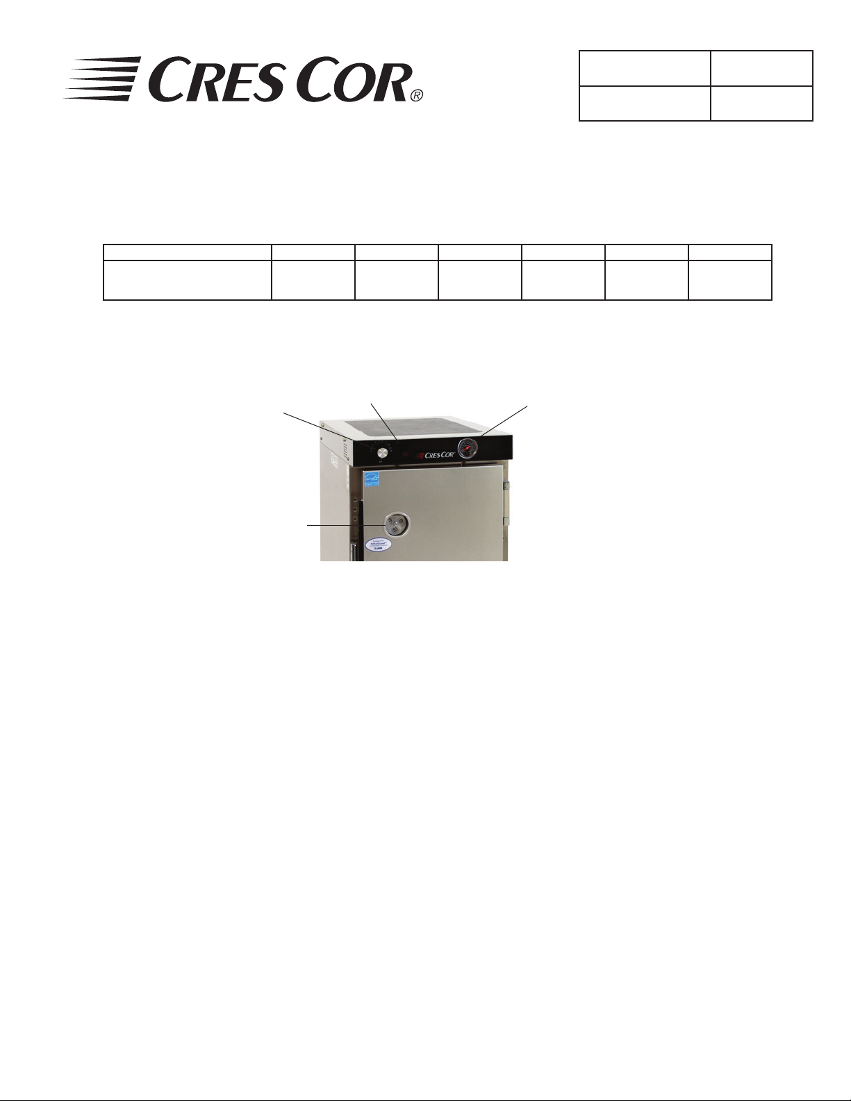
Thermometer
Insulated Hand-Lift
Holding Cabinet
Rev. 10 (4/13) Page 1 of 5
60
60
FL-0520-4
1
1
5-15
6-15
Door Vent
FIGURE 1
HOW TO INSTALL UNIT:
1. Lay cabinet down on its back; look at the bottom
plate and note that every corner has a (4) hole
pattern that matches up with the holes on the caster
plate.
2. Remove the (16) screws that are in those caster
mounting holes.
3. Unpack casters and attach them into the (16) holes
with the screws provided (add brake casters to
front of cabinet).
4. Plug cord into 15 amp. wall outlet.
5. Place cabinet in a well-ventilated area.
6. Push the switch on, turn the thermostat to No. 10
and run the unit for one hour.
NOTE: DO NOT PUT IN FOOD! This step is to burn
off manufacturing oils and excess adhesive.
HOW TO OPERATE UNIT: (Figure 1)
1. Push switch “ON”. Yellow light will come on.
2. Turn thermostat to the temperature you need.
NOTE: No. 6½ setting will give you about 180° F
(82°C). Proper food holding temperature is
140° F (60°C) or higher.
3. Preheat cabinet for 45 minutes.
4. Put food into cabinet.
5. Turn the wing nut on the door vent to open the vent
when less humidity is needed.
To Turn Off Unit:
Push switch “OFF”. The yellow light will go off.
NOTE: Thermometer will give the inside cabinet
temperature.
7. Let the cabinet cool and wipe inside clean with
detergent and hot water before use.
Call Toll-free: 877-CRES COR (273-7267) • Fax: 800-822-0393 • www.crescor.com
Page 2
Insulated Hand-Lift
Holding Cabinet
Rev. 10 (4/13) Page 2 of 5
FL-0520-4
OPERATING and MAINTENANCE INSTRUCTIONS
FOR HAND-LIFT HOLDING CABINET, H-339-135-BK SERIES
WARNING
BEFORE CLEANING CABINET:
1. Unplug power cord from wall.
2. Do NOT hose cabinet with water.
3. Do NOT get water on controls.
4. Do NOT use abrasives or harsh
chemicals.
SOIL CLEANER METHOD
DIRT Mild detergent* and hot wa-
CABINET
Inside and
Outside
(Aluminum)
RACK
INSERT
Removable
(Stainless
Steel)
FINGERPRINTS,
GREASE, OIL
WATER SPOTS Mild abrasive cleaner. Wipe with damp cloth.
ROUTINE
CLEANING
STUBBORN SPOTS
AND STAINS
BURNT-ON FOODS
OR GREASE
HARD WATER SPOTS
AND SCALE
5925 Heisley Road • Mentor, OH 44060-1833
Hints:
1. Wipe up spills as soon as possible.
2. Clean cabinet regularly to avoid heavy dirt build-up.
3. Make a test spot with cleaner.
4. Follow manufacturer’s directions on cleaner.
5. Do not mix cleaners
6. Avoid drips and splashes.
HOW TO CLEAN UNIT:
1. Use soft, damp cloth.
ter, or mild abrasive cleaner.
Steam (no strong alkaline
additive).
Detergent* and hot water. 1. Wipe with soft, damp cloth.
Chemical cleaner for
aluminum.
Mild abrasive cleaner.
Oily or waxy cleaner.
Soap, ammonia, or
detergent* and water.
Mild abrasive made for
stainless steel.
Chemical oven cleaner. 1. Apply generous coating.
Vinegar. 1. Swab or wipe with cloth.
2. Rinse with hot water.
3. Wipe dry.
1. Rinse after steam cleaning.
2. Wipe dry.
2. Rinse with hot water.
3. Wipe dry.
Follow cleaner manufacturer’s directions.
Apply with soft, clean cloth.
1. Sponge on with cloth.
2. Rinse.
3. Apply with damp sponge or cloth.
4. Rub lightly.
2. Allow to stand for 10-15 minutes.
3. Rinse.
4. Repeat application if necessary.
2. Rinse and dry.
* Mild detergents include soaps and non-abrasive cleaners.
Call Toll-free: 877-CRES COR (273-7267) • Fax: 800-822-0393 • www.crescor.com
Page 3

5925 Heisley Road • Mentor, OH 44060-1833
OPERATING and MAINTENANCE INSTRUCTIONS
FOR HAND-LIFT HOLDING CABINET, H-339-135-BK SERIES
HOW TO REVERSE DOOR HARDWARE
FOR OPPOSITE HAND (Refer to Figure 2 [hinge]):
1. Pop off hinge covers with a screwdriver.
2. Remove screws from hinges to door (Item 1) and hinge
brackets to cabinet (Item 2).
3. Remove screws from latch to door and latch bracket to
cabinet.
NOTE: Keep hinges and latch strike mounted to the
brackets.
4. Remove all remaining screws from both sides of door
and cabinet in that area. Keep all screws.
5. Turn latch strike bracket 180° and mount it to the
opposite side of the cabinet with the same screws you
removed. Do the same with the hinge brackets.
6. Line up (4) latch holes to door holes on the opposite
side of the door. Mount latch with same screws that
were removed.
7. Mount hinges to the opposite side of the door and snap
on the hinge covers.
8. Plug remaining holes with screws
.
C'SK SCREWS
#10-24 X 3/4"
Insulated Hand-Lift
Holding Cabinet
Rev. 10 (4/13) Page 3 of 5
DOOR
TOP
SCREWS-T.H.M
#10-24 X 1/2"
FIGURE 2
FL-0520-4
CABINET
BODY
HINGE
COVER
TROUBLE-SHOOTING CHART
FAILURE POSSIBLE CAUSE/CHECK
1. Unit does not heat: 1a. Thermostat turned up.
1b. Switch is “ON”.
1c. Cord is plugged into outlet.
1d. Circuit breaker/fuse for
wall outlet.
2. Unit will not turn off: 2a. Thermostat turned down.
2b. Switch is “OFF”.
If cause is none of the above, refer to our list of
authorized service agencies, FL-1400.
Instructions for replacing parts are
included in replacement parts kits.
REPLACEMENT PARTS:
120 V. 240 V.
Cord Set 0810-029 0810-139
Switch Kit 0808-113-K 0808-113-01-K
Heater Kit 0811-066-K 0811-066-1K
Thermostat Kit 0848-008-ACK 0848-008-ACK
Terminal Block 0852-091 0852-091
Door Latch Kit 1006-142-K1
Hinge Kit 0519-074-K
Thermometer Kit 5238-030-K
Gasket Kit 0861-077
Rack Insert 1104-083-K
Door Assembly
(Reversible)
Leg Kit 1206-064
Caster Kit, 3” diameter 5544
Caster Kit, 5” diameter 5518-BK
5508-087-K
Call Toll-free: 877-CRES COR (273-7267) • Fax: 800-822-0393 • www.crescor.com
Page 4

Insulated Hand-Lift
Holding Cabinet
FL-0520-4
Rev. 10 (4/13) Page 4 of 5
OPERATING and MAINTENANCE INSTRUCTIONS
FOR HAND-LIFT HOLDING CABINET, H-339-135-BK SERIES
5925 Heisley Road • Mentor, OH 44060-1833
7
*
16
*
G
W
5-15P
G
16
6-15P
* WIRE # 16 GROUND
TO INNER BODY
1
>
2
2
>
<
S.W.
3
3
5
A
1
2
<
1
>
>
17
S
o
t
4 5
4
6
4
8
6 7 8 9 10
* SEE NOTE "A"
6
5
>
TB
8
TCB
9
11
10
H1
H2
12
14
LEGEND
ITEM
H1 HEATER-BOTTOM
H2&3 HEATER-RIGHT & LEFT SIDE
5-15P PLUG (POWER CORD) 120V. 15A.
6-15P PLUG (POWER CORD) 240V. 15A.
S SENSOR-AIR
SW SWITCH-POWER (LIGHTED)
TB TERMINAL BLOCK
TCB TEMPERATURE CONTROL BOARD
SLEEVING (12-PLACES)
DESCRIPTION
H3
*NOTE "A"
FOR 120 V.: ATTACH WIRE #5 TO TERMINAL #9
FOR 240 V.: ATTACH WIRE #5 TO TERMINAL #10
ADD WIRE NUT, 0817-004 TO UNUSED LEAD
Call Toll-free: 877-CRES COR (273-7267) • Fax: 800-822-0393 • www.crescor.com
Page 5

5925 Heisley Road • Mentor, OH 44060-1833
INSTALLATION INSTRUCTIONS
for NON-SKID MAT FOR COUNTER TOP USAGE
CABINET REAR
4
Insulated Hand-Lift
Holding Cabinet
Rev. 10 (4/13) Page 5 of 5
FL-0520-4
2
1
BOTTOM CABINET
3
DOOR
1. Lay cabinet down and clean the bottom of the cabinet.
2. Pull paper backing off the adhesive side of the (4) pieces of spongy material found inside the cabinet.
3. Install the front & rear pieces, 17¾” long, (items 3 & 4) across the edge of the bottom plate as shown.
4. Install side pieces, 21¼” long (items 1 & 2) along the edge in between the front and rear pieces.
5. All gaps around the bottom need to be sealed with N.S.F. 51 approved sealant, e.g. Sil-Bond #4500.
Call Toll-free: 877-CRES COR (273-7267) • Fax: 800-822-0393 • www.crescor.com
 Loading...