

Page 1
5925 Heisley Road • Mentor, OH 44060-1833
877/CRES COR (273-7267) • 440/350-1100
Fax: 440/350-7267 • www.crescor.com
OPERATING and MAINTENANCE INSTRUCTIONS
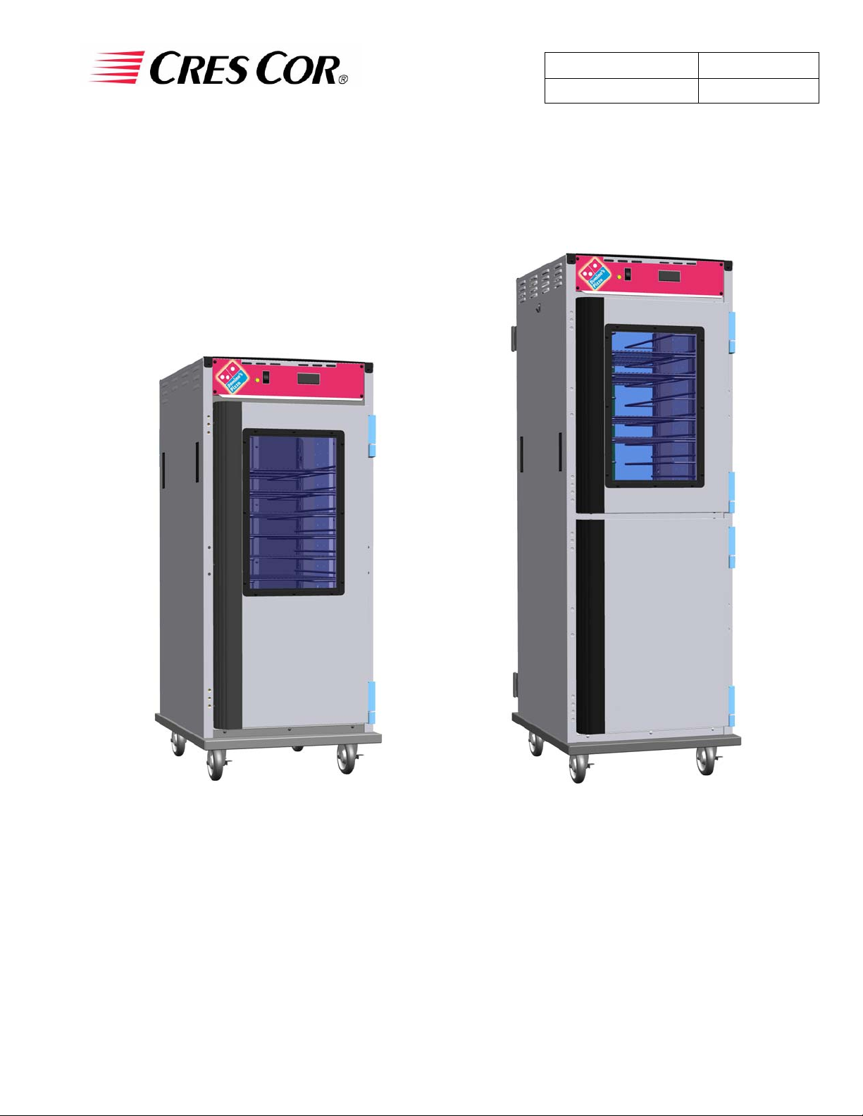
Models: H138NPSCDOM Series Hot Cabinets
Holding Cabinet
Rev. 4 (6/07) Page 1 of 8
FL-2331
H138NPSCDOM2
Cabinet model number: __________________________________.
Cabinet serial number: __________________________________.
Authorized Service Agency: _______________________________.
Ph:_______________________. Fax: _______________________.
Keep this manual for future reference.
H138NPSCDOM3
Page 2
5925 Heisley Road • Mentor, OH 44060-1833
877/CRES COR (273-7267) • 440/350-1100
Fax: 440/350-7267 • www.crescor.com
OPERATING and MAINTENANCE INSTRUCTIONS
Models: H138NPSCDOM Series Hot Cabinets
ELECTRICAL SPECIFICATIONS:
Model No. Volts Watts Amps Hertz Phase NEMA
Holding Cabinet
Rev. 4 (6/07) Page 2 of 8
FL-2331
H138NPSCDOM2 120 1400 11.7 60 1 5-15P
H138NPSCDOM3 120 2000 16.6 60 1 5-20P
NOTE: The above model numbers are basic models.
They may be followed by letters: L
INSTALLATION:
1. Remove all paper and packing material from
inside of cabinet.
, R, or ending with S.
HOW TO HOLD:
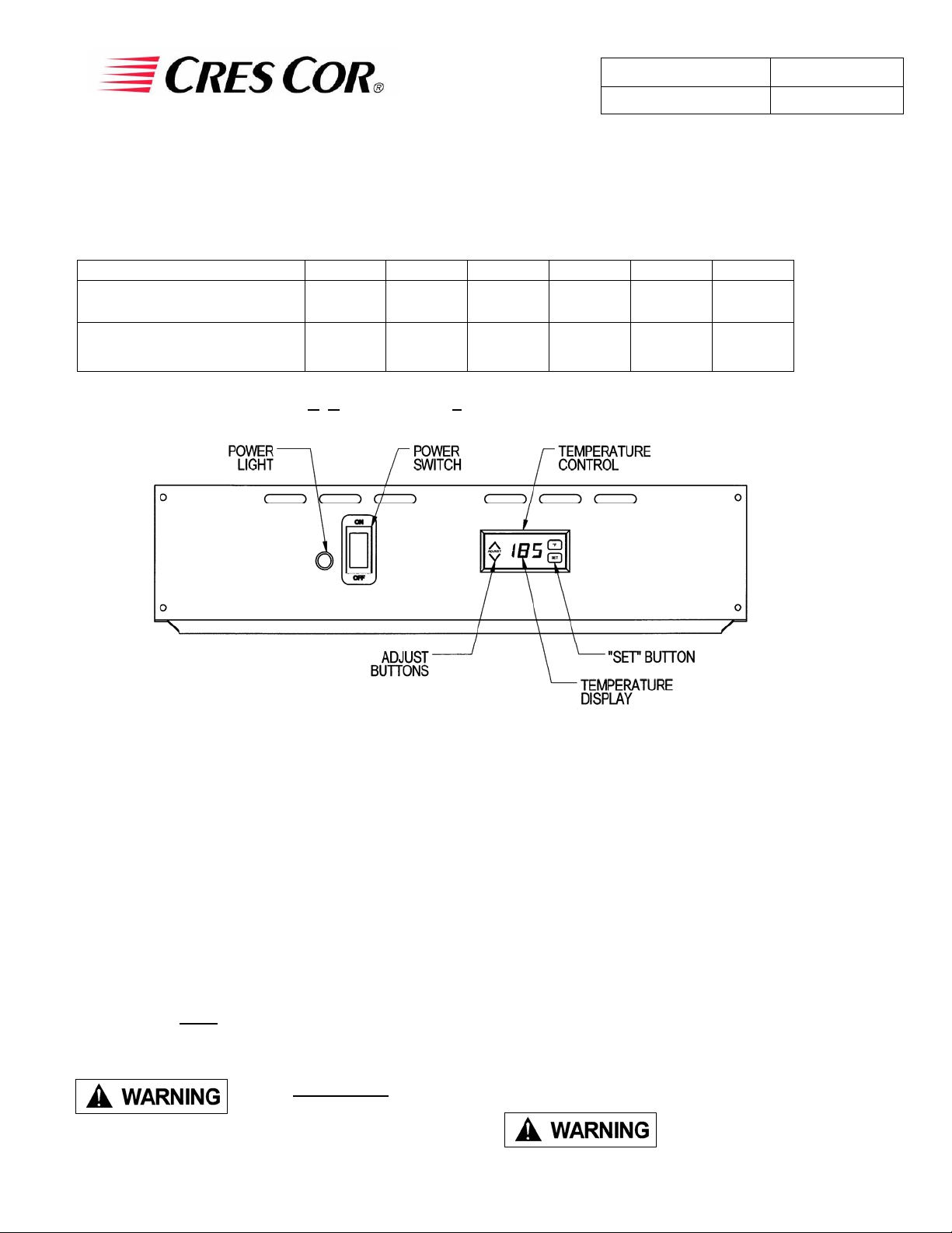
1. Push POWER switch to “ON.”
Yellow POWER LIGHT will come on.
2. Remove protective paper and vinyl material
from outside surfaces of cabinet.
3. Place the cabinet in a well-ventilated area.
4. Place cabinet on level floor.
5. Plug cord end into proper wall outlet.
FIRST TIME START-UP:
1. Push the POWER switch to “ON”, and run
the unit for one hour.
NOTE: DO NOT
PUT FOOD INTO CABINET!
This step is to burn off manufacturing oils and
excess adhesive.
Air is VERY HOT when
door is opened.
2. Let the cabinet cool and wipe inside clean
with detergent and hot water before first use.
2. Push the “SET” button on the TEMPERATURE
CONTROL. The TEMPERATURE DISPLAY
will show “SP1” (setpoint 1).
3. Press “SET” again and the current setpoint
temperature will be displayed.
4. Press the ¿À ADJUST buttons to adjust to the
desired temperature.
5. Press “SET” to save the temperature setting.
6. Preheat cabinet for 45 minutes.
7. Put product into cabinet.
NOTE: Proper food holding temperature is
140°F/60°C or higher.
Blower inlet guard must
be in place before
operating cabinet.
Page 3
5925 Heisley Road • Mentor, OH 44060-1833
877/CRES COR (273-7267) • 440/350-1100
Fax: 440/350-7267 • www.crescor.com
OPERATING and MAINTENANCE INSTRUCTIONS
Models: H138NPSCDOM Series Hot Cabinets
Holding Cabinet
Rev. 4 (6/07) Page 3 of 8
FL-2331
the cabinet: Unplug cord from wall.
Do NOT hose cabinet with water.
Do NOT get water on controls.
Do NOT use abrasives or harsh
chemicals.
HOW TO CLEAN THE UNIT:
Soil Cleaner Method
ROUTINE CLEANING
CABINET
Inside and
Outside
(Stainless
Steel)
STUBBORN SPOTS
AND STAINS
BURNT-ON FOODS OR
GREASE
BEFORE cleaning
Soap, Ammonia, or mild
*detergent and water.
Mild abrasive made for
stainless steel.
Chemical oven cleaner for
stainless steel.
Cleaning hints:
1. Wipe up spills as soon as possible.
2. Clean cabinet regularly to avoid heavy dirt build-up.
3. Make a test spot with cleaner.
4. Follow manufacturer’s directions on cleaner.
5. Do not mix cleaners.
6. Avoid drips and splashes
1. Sponge on with cloth.
2. Rinse with water.
3. Wipe dry.
1. Apply with damp sponge or cloth.
2. Rub lightly.
Follow oven cleaner manufacturer’s
directions.
HARD WATER SPOTS
and SCALE
*Mild detergents include soaps and non-abrasive cleaners.
Vinegar
1. Swab or wipe with cloth.
2. Rinse and dry.
Page 4

5925 Heisley Road • Mentor, OH 44060-1833
877/CRES COR (273-7267) • 440/350-1100
Fax: 440/350-7267 • www.crescor.com
OPERATING and MAINTENANCE INSTRUCTIONS
Models: H138NPSCDOM Series Hot Cabinets
TROUBLE-SHOOTING CHART:
FAILURE POSSIBLE CAUSE
1. POWER LIGHT (Yellow)
does NOT light.
2. Unit does not heat. 2a. Temperature control is set too low.
3. Unit gets too hot or
won’t shut off.
4. Blower does not work
or makes noise.
5. GFCI device trips. 5a. The insulation inside the heating element may have absorbed some
GFCI (ground-fault circuit interrupter): A GFCI receptacle is a device that de-energizes a circuit when it
detects an unsafe flow of current to ground. The intention of a GFCI device is to minimize the potential for an
electrical shock.
Holding Cabinet
1a. Switch is “OFF”.
1b. Cord unplugged from wall outlet.
1c. Circuit breaker/fuse to wall outlet tripped/blown.
2b. Switch is “OFF”.
3a. Defective electrical parts. UNPLUG UNIT FROM WALL OUTLET.
4a. Defective blower.
moisture. This may have occurred if the cabinet has not been used for a
long period of time or during shipping and storage of the cabinet. Plug the
cabinet into a non-GFCI outlet and set the temperature control to its
maximum. Let the cabinet run for about 1 hour to dry out the heating
element from any moisture may have been absorbed. If the circuit
breaker trips, call the factory Authorized service agent. After drying
the heating element, plug cabinet into the GFCI receptacle; the cabinet
should run properly. If the GFCI device continues to trip, call the
factory Authorized service agent
Rev. 4 (6/07) Page 4 of 8
FL-2331
If cause is none of the above, refer to our list of Authorized Service Centers, FL-1400
Page 5

5925 Heisley Road • Mentor, OH 44060-1833
877/CRES COR (273-7267) • 440/350-1100
Fax: 440/350-7267 • www.crescor.com
OPERATING and MAINTENANCE INSTRUCTIONS
Models: H138NPSCDOM Series Hot Cabinets
REPLACEMENT PARTS:
Holding Cabinet
Rev. 4 (6/07) Page 5 of 8
FL-2331
Item Description
1 Blower Kit 0769-180-01-ALK
2 Heater Kit, Air 1370W 0811-289-K
1920W 0811-022-K
3 High Limit 0848-060
4 Power Switch 0808-116
5 Power Light 0769-094
6 Relay 0857-130
7 Temperature controller 0848-075-DOM
8 Transformer (used with Temp controller) 0769-159
9 Terminal Block 0852-093
10 Vent Fan 0769-165
Power Cord 15A 0810-029-06
20A 0810-065-12
120V
Page 6

5925 Heisley Road • Mentor, OH 44060-1833
877/CRES COR (273-7267) • 440/350-1100
Fax: 440/350-7267 • www.crescor.com
OPERATING and MAINTENANCE INSTRUCTIONS
Models: H138NPSCDOM Series Hot Cabinets
REPLACEMENT PARTS: (continued)
Holding Cabinet
Rev. 4 (6/07) Page 6 of 8
FL-2331
Cabinet Replacement Parts: H138NPSCDOM2
Item Description Part No.
1 Caster 0569-306
2 Caster with brake 0569-306-B
3 Gasket, doors 0861-264
4 Post, wire angle 0696-169
5 Wire angle Set of 2 0621-281-K
6 Wire shelf 1170-005
7 Wire blower inlet guard 1170-211
8 Door, front 1221-564
Item Description
9 Door, back 1221-565
10 Handle, door 0911-099-AB
11 Window, wide 0574-133
12 Window, narrow 0574-155
13 Hinge Kit, lift off Set of 2 0519-087-K
14 Air tunnel 0546-142
Part No.
Page 7

5925 Heisley Road • Mentor, OH 44060-1833
877/CRES COR (273-7267) • 440/350-1100
Fax: 440/350-7267 • www.crescor.com
OPERATING and MAINTENANCE INSTRUCTIONS
Models: H138NPSCDOM Series Hot Cabinets
REPLACEMENT PARTS: (continued)
Holding Cabinet
Rev. 4 (6/07) Page 7 of 8
FL-2331
Cabinet Replacement Parts: H138NPSCDOM3
Item Description Part No.
1 Caster 0569-306
2 Caster with brake 0569-306-B
3 Gasket, front doors 0861-245
4 Gasket, back door 0861-246
5 Post, wire angle 0696-228
6 Wire angle Set of 2 0621-281-K
7 Wire shelf 1170-005
8 Wire blower inlet guard 1170-211
9 Door, front, window 1221-535-01
Item Description
10 Door, front, solid 1221-534
11 Door, back, window 1221-550
12 Handle, door 0911-100-AB
13 Latch, door 1006-120-01-K
14 Window, wide 0574-133
15 Window, narrow 0574-144
16 Hinge Kit, lift off Set of 2 0519-087-K
17 Hinge, butt type 0519-089
18 Air tunnel 0546-120
Part No.
Page 8

5925 Heisley Road • Mentor, OH 44060-1833
877/CRES COR (273-7267) • 440/350-1100
Fax: 440/350-7267 • www.crescor.com
OPERATING and MAINTENANCE INSTRUCTIONS
Models: H138NPSCDOM Series Hot Cabinets
WIRING DIAGRAM
Holding Cabinet
Rev. 4 (6/07) Page 8 of 8
FL-2331
 Loading...