

Page 1
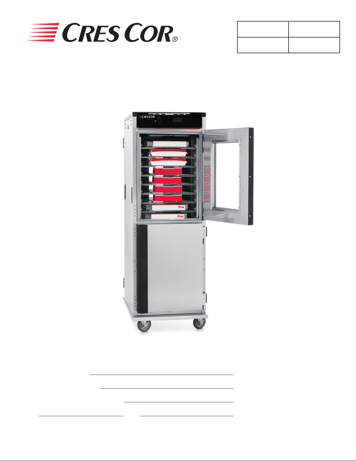
Holding Cabinet
FL-2331
5925 Heisley Road • Mentor, OH 44060-1833
OPERATING and MAINTENANCE INSTRUCTIONS
Models: H138NPSCMQ Series Hot Cabinet
Rev. 2 (12/11) Page 1 of 7
Cabinet model number:
Cabinet serial number:
Authorized Service Agency:
Ph: Fax:
Keep this manual for future reference.
Page 2
Holding Cabinet
FL-2331
Rev. 2 (12/11) Page 2 of 7
5925 Heisley Road • Mentor, OH 44060-1833
OPERATING and MAINTENANCE INSTRUCTIONS
Models: H138NPSC Series Hot Cabinet
ELECTRICAL SPECIFICATIONS:
Model No. Volts Watts Amps Hertz Phase NEMA
H138NPSC
Note: The above model number is a basic model. It will be followed by numbers and letters.
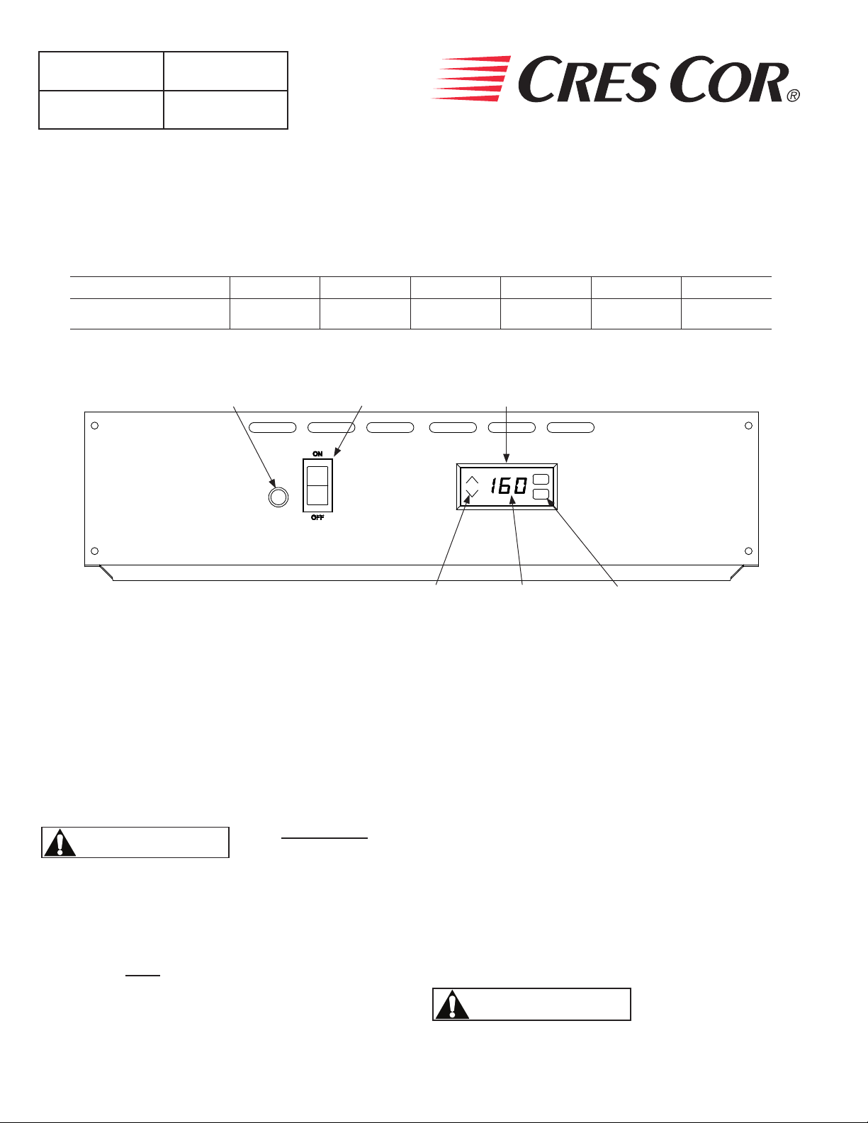
POWER
LIGHT
120 2000 16.6 60 1 5-20P
POWER
SWITCH
TEMPERATURE
ADJUST
CONTROL
°F
SET
ADJUST
BUTTONS
INSTALLATION:
1. Remove all paper and packing material from
inside of cabinet.
2. Remove protective paper and vinyl material from
outside surfaces of cabinet.
3. Place the cabinet in a well-ventilated area.
4. Place cabinet on level oor.
5. Plug cord end into proper wall outlet.
Air is VERY HOT
WARNING
when door is opened.
FIRST TIME START-UP:
1. Push the POWER switch to “ON”, and run the
unit for one hour.
NOTE: DO NOT PUT FOOD INTO CABINET!
This step is to burn off manufacturing oils and excess
adhesive.
2. Let the cabinet cool and wipe inside clean with
detergent and hot water before rst use.
TEMPERATURE
DISPLAY
“SET” BUTTON
HOW TO HOLD:
1. Push POWER switch to “ON.” Yellow POWER
LIGHT will come on.
2. Push the “SET” button on the TEMPERATURE
CONTROL. The TEMPERATURE DISPLAY will
show “SP1” (set point 1).
3. Press “SET” again and the current set point temperature
will be displayed.
4. Press the ADJUST buttons to adjust to the
desired temperature.
5. Press “SET” to save the temperature setting.
6. Preheat cabinet for 45 minutes.
7. Put product into cabinet.
NOTE: Proper food holding temperature is
140°F/60°C or higher.
WARNING
Blower inlet guard must be in place before
operating cabinet.
Page 3
Holding Cabinet
FL-2331
5925 Heisley Road • Mentor, OH 44060-1833
MAINTENANCE INSTRUCTIONS
WARNING
BEFORE cleaning the cabinet:
1. Unplug the cabinet from the wall.
2. Allow cabinet to cool.
1. Do NOT use abrasives (steel wool) or harsh
chemicals (chlorine, bromine, iodine or ammonia).
2. Do NOT use a water sprayer (pressure sprayer) to
clean the cabinet.
Rev. 2 (12/11) Page 3 of 7
Cleaning hints:
1. Wipe up spills as soon as possible.
2. Clean cabinet daily to avoid heavy dirt build-up.
3. Make a test spot with cleaner:
a) Follow manufacturer’s directions on cleaner.
b) Do not mix cleaners.
c) Avoid drips and splashes.
HOW TO CLEAN THE UNIT:
Soil Cleaner Method
DAILY CLEANING
CABINET
Inside and
Outside
(Stainless Steel)
STUBBORN SPOTS AND
STAINS
BURNT-ON FOODS OR
GREASE
HARD WATER SPOTS
and SCALE
*Mild detergents include soaps and non-abrasive cleaners.
Note: Gaskets are removable for cleaning.
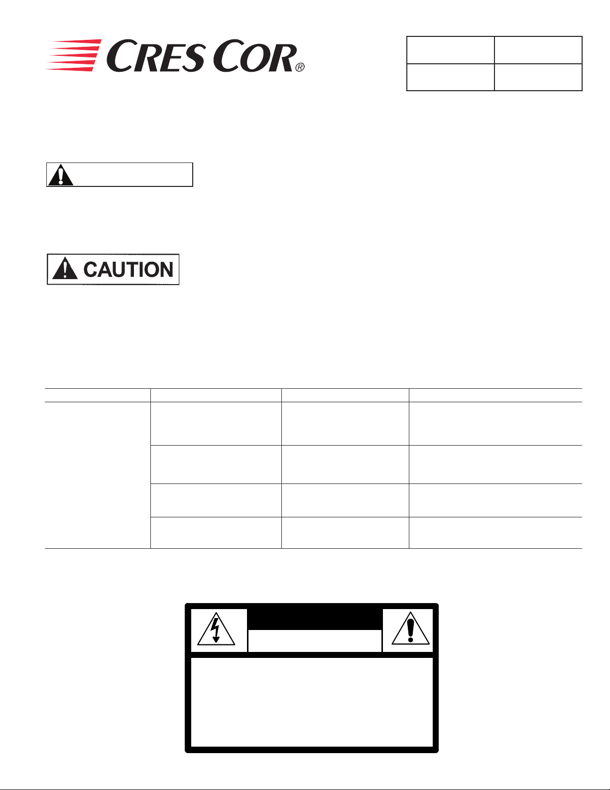
WARNING: TO REDUCE THE RISK OF FIRE OR ELECTRIC SHOCK,
Mild detergent and hot
water.
Mild abrasive made for
stainless steel.
Chemical oven cleaner for
stainless steel.
Vinegar
WARNING
RISK OF FIRE OR ELECTRIC SHOCK
DO NOT OPEN
1. Sponge on with cloth.
2. Rinse with water.
3. Wipe dry.
1. Apply with damp sponge or cloth.
2. Rub lightly.
3. Rinse with water and wipe dry.
Follow oven cleaner manufacturer’s
directions.
1. Swab or wipe with cloth.
2. Rinse and dry.
DO NOT REMOVE COVER (OR BACK)
NO USER-SERVICEABLE PARTS INSIDE
REPAIR SHOULD BE DONE BY AUTHORIZED SERVICE
PERSONNEL ONLY
Page 4

Holding Cabinet
FL-2331
Rev. 2 (12/11) Page 4 of 7
5925 Heisley Road • Mentor, OH 44060-1833
TROUBLE-SHOOTING
FAILURE POSSIBLE CAUSE
1. POWER LIGHT (Yellow) does NOT light.
2. Unit does not heat. 2a. Temperature control is set too low.
3. Unit gets too hot or won’t shut off. 3a. Defective electrical parts.
4. Blower does not work or makes noise. 4a. Defective blower.
5. GFCI device trips. 5a. The insulation inside the heating element may
1a. Switch is “OFF”.
1b. Cord unplugged from wall outlet.
1c. Circuit breaker/fuse to wall outlet tripped/blown.
1d. Blown fuse
2b. Switch is “OFF”.
UNPLUG UNIT FROM WALL OUTLET.
have absorbed some moisture. This may have
occurred if the cabinet has not been used for a long
period of time or during shipping and storage of the
cabinet. Plug the cabinet into a non-GFCI outlet and
set the temperature control to its maximum. Let the
cabinet run for about 1 hour to dry out the heating
element from any moisture may have been absorbed.
If the circuit breaker trips, call the factory Authorized
service agent. After drying the heating element, plug
cabinet into the GFCI receptacle; the cabinet should
run properly. If the GFCI device continues to trip, call
the factory Authorized service agent.
GFCI (ground-fault circuit interrupter): A GFCI receptacle is a device that de-energizes a circuit when it
detects an unsafe ow of current to ground. The intention of a GFCI device is to minimize the potential for an
electrical shock.
If cause is none of the above, refer to our list of Authorized Service Centers, FL-1400
Page 5

Holding Cabinet
FL-2331
5925 Heisley Road • Mentor, OH 44060-1833
REPLACEMENT PARTS
Include all information on nameplate when ordering parts
3
2
1
9
8
Rev. 2 (12/11) Page 5 of 7
1
10
11
5
12
4
7
ITEM DESCRIPTION 120V
13
1 Blower Kit 0769-180-01-ALK
2 Heater Kit, Air 1850 Watt 0811-022-K
3 High Limit 0848-060
4 Power Switch 0808-116-K
5 Power Light 0766-094
Relay - Solid State (not shown) 0857-134
7 Temperature controller 0848-075-CC-K
8
Transformer (used with Temp controller)
0769-159
9 Terminal Block (4 pole) 0852-093
Terminal Block (2 pole) 0852-091
10 Vent Fan 0769-165
Power Cord (not shown) 20 Amp 0810-065-14-LK
11 Fan Guard 0769-167
12 Cord Bracket 0553-757
13 Strain Relief 90° 0818-095
Page 6

Holding Cabinet
FL-2331
Rev. 2 (12/11) Page 6 of 7
Include all information on nameplate when ordering parts
6
9
14
12
5925 Heisley Road • Mentor, OH 44060-1833
REPLACEMENT PARTS
8
7
5
17
13
15
11
4
1
10
18
3
2
16
CABINET REPLACEMENT PARTS: H138NPSCDOM3
Item Description Part No. Item Description Part No.
1 Caster 0569-306-K 11 Door, back, window 1221-550
2 Caster with brake 0569-306-BK 12 Handle, door 0911-111
3 Gasket, front doors 0861-245 13 Latch, door 1006-120-01-K
4 Gasket, back door 0861-246 14 Window, wide 0574-133
5 Post, rack 0696-228 15 Window, narrow 0574-144
6 Angle, Wire, set of 2 0621-281-K 16 Hinge Kit, lift off, set of 2 0519-087-K
7 Wire shelf 1170-005 17 Hinge, butt type 0519-089
8 Wire blower inlet guard 1170-211 18 Air tunnel 0546-120
9 Door, front, window 1221-535-01 Door stop 0553-740
10 Door, front, solid 1221-534
Page 7

Holding Cabinet
FL-2331
5925 Heisley Road • Mentor, OH 44060-1833
WIRING DIAGRAM
PILOT
LIGHT
PWR SWITCH
1
2
BLOWER
19
20
9
7
8
2
1
25
15
16
26
12
3
HEATER AIR
6
MOTOR
Rev. 2 (12/11) Page 7 of 7
5-15P
OR L5-15P*
120V, 15A
W
G
G
5-20P
OR L5-20P*
120V, 20A
WHITE
8
7
19
3
9
A2 A1
10
5
BLACK
20
4
W
G
GREEN
*FOR TWISTLOCK OPTION
G
5
L1 T1
4
SOLID STATE RELAY
TEMPERATURE
HIGH
LIMIT
25
16
15
2
1
5
AC
13
AC
14
W
WHITE
B
BLACK
CONTROL
C
NO
t°
12
10
13
110V/220
TRANSFORMER
HIGH
LIMIT
22
26
4
3
MOTOR
BLOWER
VENT
VENT
FAN
FAN
8
14
 Loading...