

Page 1
5925 Heisley Road • Mentor, OH 44060-1833
5925 Heisley Road • Mentor, OH 44060-1833
OPERATING and MAINTENANCE INSTRUCTIONS
OPERATING and MAINTENANCE INSTRUCTIONS
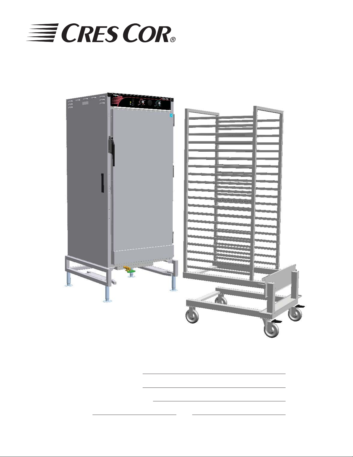
Models: H137WSRR-C Series Companion Holding Cabinet
Models: H137WSRR-C Series Companion Holding Cabinet
FL-2330
FL-2330
Rev. 0 (2/07)
Rev. 0 (2/07)
Models: H137WSRRC2020 SERIES for use with Convotherm C2020 Roll-In Rack (not included).
Cabinet model number:
Cabinet serial number:
Authorized Service Agency:
Ph: Fax:
Keep this manual for future reference.
Page 2
FL-2330
Rev. 0 (2/07)
5925 Heisley Road • Mentor, OH 44060-1833
TABLE OF CONTENTS
SUBJECT PAGE
INSTALLATION INSTRUCTIONS .......................................................................................... 2
Illustration (Leg Adjustment), Figure 1 ............................................................................2
Illustration (Drain Valve), Figure 2 ..................................................................................2
OPERATING INSTRUCTIONS ................................................................................................3
Illustration (Control Panel), Figure 3 ...............................................................................3
MAINTENANCE INSTRUCTIONS
How to Clean the Unit ......................................................................................................4
Trouble Shooting Guide ................................................................................................... 5
Replacement Parts (Cabinet) ............................................................................................6
Illustration (Cabinet Parts) ............................................................................................... 7
Replacement Parts (Power Unit) ...................................................................................... 8
Wiring Diagram ................................................................................................................9
How to Reverse the Door Opening .................................................................................. 10
SERVICE POLICY and AGENCY LIST ..........................................................................FL-1400
WARNING
RISK OF FIRE OR ELECTRIC SHOCK
DO NOT OPEN
WARNING: TO REDUCE THE RISK OF FIRE OR ELECTRIC SHOCK,
DO NOT REMOVE COVER (OR BACK)
NO USER-SERVICEABLE PARTS INSIDE
REPAIR SHOULD BE DONE BY AUTHORIZED SERVICE
PERSONNEL ONLY
Page 3
Companion
Holding Cabinet
FL-2330
5925 Heisley Road • Mentor, OH 44060-1833
Rev. 0 (2/07) Page 1 of 10
OPERATING and MAINTENANCE INSTRUCTIONS
Models: H137WSRR-C Series Companion Holding Cabinet
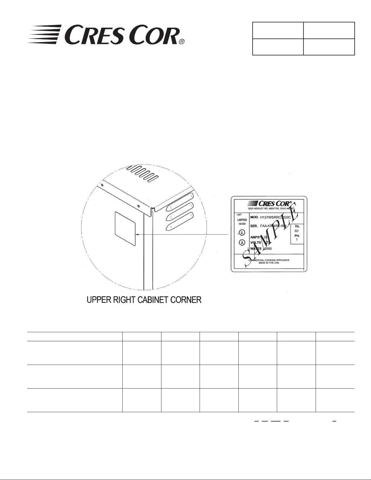
IDENTIFYING YOUR CABINET:
Look for this label on the back of your cabinet. This information is needed when calling for questions or service.
ELECTRICAL SPECIFICATIONS:
Model No. Volts Watts Amps Hertz Phase NEMA
H137WSRRC2020C
H137WSRRC2020C208
H137WSRRC2020C240
Note: The above model numbers are basic models. They may be followed by letters: L, M, 2M, D, or ending with S.
120 1920 16.0 60 1 5-20P
208 2000 10.0 60 1 6-15P
240 2000 8.6 60 1 6-15P
Page 4
Companion
Holding Cabinet
FL-2330
Rev. 0 (2/07) Page 2 of 10
OPERATING and MAINTENANCE INSTRUCTIONS
Models: H137WSRR-C Series Companion Holding Cabinet
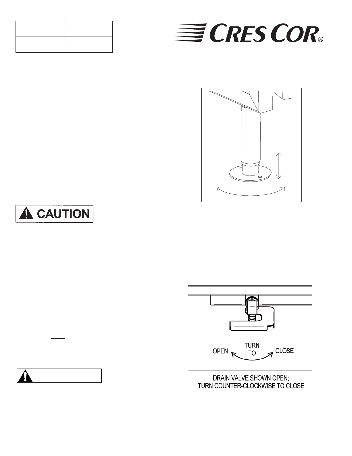
HOW TO INSTALL UNIT:
Remove all paper and packing material from inside of 1.
cabinet.
Remove protective paper and vinyl material from 2.
outside surfaces of cabinet.
Place the cabinet in a well-ventilated area.3.
Place cabinet on level fl oor. (For cabinets with legs, 4.
adjust the legs of the cabinet to ensure proper fi t of rack
into cabinet. See Fig. 1)
Plug cord end into proper wall outlet.5.
Fill water pan with 4 gallons (15 liters) of water.6.
Make sure green drain valve is closed. See Figure 2.
Use of treated or
soft water may be
required for proper
operation and to maintain warranty.
5925 Heisley Road • Mentor, OH 44060-1833
Figure 1 Leg Adjustment
7. Push POWER switch to “ON.” Yellow POWER
LIGHT will come on.
8. Push the “SET” button on the TEMPERATURE
CONTROL. The TEMPERATURE DISPLAY will
show “SP1” (set point 1).
9. Press “SET” again and the current set point temperature
will be displayed.
10. Press the ADJUST buttons to adjust to 200°F
(93°C).
11. Run the unit for one hour.
NOTE: DO NOT PUT FOOD IN CABINET!
This step is to burn off manufacturing oils and excess
adhesive.
WARNING
Air is VERY HOT when door is opened.
Figure 2 Drain Valve
12. Let the cabinet cool and wipe inside clean with
detergent and hot water before fi rst use.
Page 5

Companion
Holding Cabinet
FL-2330
5925 Heisley Road • Mentor, OH 44060-1833
OPERATING and MAINTENANCE INSTRUCTIONS
Models: H137WSRR-C Series Companion Holding Cabinet
Yellow
Light
“On-Off”
Switch
( I )
ON
( 0 )
OFF
POWER
HOW TO HOLD:
No water is needed in pan.1.
Push POWER switch to “ON.” Yellow POWER 2.
LIGHT will come on.
Push the “SET” button on the TEMPERATURE 3.
CONTROL. The TEMPERATURE DISPLAY will
show “SP1” (set point 1).
Press “SET” again and the current set point temperature 4.
will be displayed.
Press the 5. ADJUST buttons to adjust to the
desired temperature.
Press “SET” to save the temperature setting.6.
Preheat cabinet for 45 minutes.7.
Put product into cabinet.8.
Thermostat
3
LOW
2
PROOF
Figure 3
4
1
“Air”
5
AIR
6
7
9
10
MEDIUM
HOLD
8
HIGH
HOLD
Thermometer
70
80
60
160
180
140
90
R
190
120
95
200
40
100
210
80
20
60
100
220
20
0
F
105
C
HOLD WITH HUMIDITY:
Fill water pan with HOT water.1.
Push POWER switch to “ON.” Yellow POWER Light 2.
will come on.
Push the “SET” button on the TEMPERATURE 3.
CONTROL. The TEMPERATURE DISPLAY will
show “SP1” (set point 1).
Press “SET” again and the current set point temperature 4.
will be displayed.
Press the 5. ADJUST buttons to adjust to the desired
temperature.
Press “SET” to save the temperature setting.6.
Turn the “HUMIDITY” thermostat to No. 9.7.
Preheat for 45 minutes.8.
Turn “AIR” thermostat to desired temperature. (See 9.
thermostat settings below.
10. Put product into cabinet
Rev. 0 (2/07) Page 3 of 10
“Humidity”
Thermostat
5
6
4
MEDIUM
HUMIDITY
7
8
HIGH
9
MOIST
10
3
LOW
2
DRY
1
R
NOTES: Proper food holding temperature is 140°F/60°C or higher.
Air is VERY HOT when door is opened.
WARNING
SOME TYPICAL THERMOSTAT SETTINGS:
Thermostat Setting Result Thermostat Setting Result
Air Humidity Cab. Temp. Humidity Air Humidity Cab. Temp Humidity
150° F Off 150° F N/A 160°F Med 160°F 50%
175°F Off 175° F N/A 160°F High 160°F 95%
200°F Off 200° F N/A 170°F Low 170°F 15%
170°F Med 170°F 35%
100°F 3½ 100°F 98% 170°F High 170°F 85%
170°F Max 170°F 90%
150°F Low 115° F 98% 200°F Low 200°F 7%
150°F Med 150° F 95% 200°F Med 200°F 15%
150°F High 150° F 95% 200°F High 200°F 40%
160°F Low 160° F 30%
Note: These settings are based on laboratory conditions and may differ from conditions at point of use. Experiment with
the settings to determine what is best for your application.
Page 6

Companion
Holding Cabinet
FL-2330
Rev. 0 (2/07) Page 4 of 10
OPERATING and MAINTENANCE INSTRUCTIONS
Models: H137WSRR-C Series Companion Holding Cabinet
MAINTENANCE: WATER PAN
Drain, wipe and fi ll water pan daily. (Clear vinyl drain
hose is provided.)
Push hose onto drain nozzle under the base.1.
Turn knob to open the drain.2.
MAINTENANCE: CABINET
Wipe the inside of cabinet after daily use. 1.
Leave doors slightly open to fully dry interior.2.
Delime or descale
water pan parts as
required, to prevent
damaging build-up.
WARRANTY COVERAGE MAY BE AFFECTED
WITHOUT PROPER CLEANING.
5925 Heisley Road • Mentor, OH 44060-1833
WARNING
BEFORE cleaning the cabinet: Unplug cord
from wall.
Do NOT hose cabinet with water.
Do NOT get water on controls.
Do NOT use abrasives or harsh chemicals.
Cleaning hints:
Wipe up spills as soon as possible.1.
Clean cabinet regularly to avoid heavy dirt build-up.2.
Make a test spot with cleaner.3.
Follow manufacturer’s directions on cleaner.4.
Do not mix cleaners.5.
Avoid drips and splashes6.
HOW TO CLEAN THE UNIT:
Soil Cleaner Method
ROUTINE CLEANING
CABINET
Inside and
Outside
(Stainless Steel)
STUBBORN SPOTS AND
STAINS
BURNT-ON FOODS OR
GREASE
HARD WATER SPOTS
and SCALE
*Mild detergents include soaps and non-abrasive cleaners.
Soap, Ammonia, or mild
*detergent and water.
Mild abrasive made for
stainless steel.
Chemical oven cleaner for
stainless steel.
Vinegar
1. Sponge on with cloth.
2. Rinse with water.
3. Wipe dry.
1. Apply with damp sponge or cloth.
2. Rub lightly.
Follow oven cleaner manufacturer’s
directions.
1. Swab or wipe with cloth.
2. Rinse and dry.
Page 7

Companion
Holding Cabinet
FL-2330
5925 Heisley Road • Mentor, OH 44060-1833
OPERATING and MAINTENANCE INSTRUCTIONS
Models: H137WSRR-C Series Companion Holding Cabinet
TROUBLE-SHOOTING CHART:
FAILURE POSSIBLE CAUSE
1. Yellow light at switch
does NOT light.
2. Unit does not heat.
3. No humidity in cabinet.
4. Unit gets too hot or
won’t shut off.
5. Blower does not work
or makes noise.
1a. Switch is “OFF”.
1b. Cord unplugged from wall outlet.
1c. Circuit breaker/fuse to wall outlet blown.
2a. Temperature Control set too low.
2b. Switch is “OFF”.
3a. Humidity Thermostat set too low.
3b. No water in water pan.
4a. Defective electrical parts. UNPLUG UNIT FROM WALL OUTLET.
5a. Defective blower.
Rev. 0 (2/07) Page 5 of 10
6a. The insulation inside the heating elements may have absorbed some
moisture. This may have occurred if the cabinet has not been used for a
long period of time or during shipping and storage of the cabinet. Drain
the water pan if needed. Plug the cabinet into a non-GFCI outlet and set
the Temperature Control to 200° (93°C). Let the cabinet run for about 1
6. GFCI device trips.
hour to dry out the heating elements from any moisture may have been
absorbed. If the circuit breaker trips, turn off cabinet, remove cord from
power source, and call the Factory Authorized Service Agent. After drying
the heating elements, plug cabinet into the GFCI receptacle; the cabinet
should run properly. If the GFCI trips, call the factory Authorized service
agent.
GFCI (ground-fault circuit interrupter): A GFCI receptacle is a device that de-energizes a circuit when it
detects an unsafe fl ow of current to ground. The intention of a GFCI device is to minimize the potential for an
electrical shock
If cause is none of the above, refer to our list of Authorized Service Agencies.
Page 8

Companion
Holding Cabinet
FL-2330
Rev. 0 (2/07) Page 6 of 10
5925 Heisley Road • Mentor, OH 44060-1833
OPERATING and MAINTENANCE INSTRUCTIONS
Models: H137WSRR-C Series Companion Holding Cabinet
CABINET REPLACEMENT PARTS:
ITEM DESCRIPTION 120V 208V 240V
1 Heater Kit, Air, 1000 Watts each 0811-074 0811-074-02 0811-074-01
2 High Limit 0848-060 0848-060 0848-060
3 Power Cord 0810-065-10 0810-039-02 0810-039-02
4 Heater Kit, Water, 2000 Watts 0811-271 0811-271 0811-271
5 Drain Valve 0898-015 0898-015 0898-015
6 Thermostat Probe Kit (probe only) 0848-008-3-ACK 0848-008-3-ACK 0848-008-3-ACK
7 Power Unit (See Page 8) 0675-069 0675-070 0675-070
8 Door - full, solid 1221-557-K
-full, w/window 1221-558-K
-half, solid, top LH, bottom, RH 1221-560-K
-half, solid, bottom LH, top, RH 1221-559-K
-half, window, top LH, bottom, RH 1221-561-K
-half, window, bottom LH, top, RH 1221-562-K
9 Gasket Kit, Body 0861-175
10 Gasket Kit, Door 0861-265
11 Hinge Kit 0519-074-K
12 Latch Kit 1006-122-01-K
13 Tunnel 0546-141
14 Cover, Water Pan 0761-020
15 Handle, Drain Valve 0911-095
16 Leg, Adjustable 1206-070
Handle, Pull (Black) 0911-102
Page 9

Companion
Holding Cabinet
FL-2330
5925 Heisley Road • Mentor, OH 44060-1833
OPERATING and MAINTENANCE INSTRUCTIONS
Models: H137WSRR-C Series Companion Holding Cabinet
CABINET REPLACEMENT PARTS:
2
1
7
Rev. 0 (2/07) Page 7 of 10
3
1
2
13
11
12
17
9
14
4
15
16
10
8
6
5
Page 10

Companion
Holding Cabinet
FL-2330
Rev. 0 (2/07) Page 8 of 10
OPERATING and MAINTENANCE INSTRUCTIONS
Models: H137WSRR-C Series Companion Holding Cabinet
REPLACEMENT PARTS FOR THE POWER UNIT:
23
22
21
5925 Heisley Road • Mentor, OH 44060-1833
26
24
19
17
18
20
25
20
19
REPLACEMENT PARTS:
ITEM DESCRIPTION 120V 208V 240V
Power Unit 0675-069 0675-070 0675-070
17 Power Light 0766-094 0766-095 0766-095
18 Power Switch 0808-116 0808-116 0808-116
19 Thermostats, (with probe) 0848-008-ACK 0848-008-ACK 0848-008-ACK
20 Knob 0595-061 0595-061 0595-061
21 Terminal Block 0852-093 0852-093 0852-093
22 Relay 0857-130 0857-102 0857-102
23 Blower Kit 0769-180-01-SSK 0769-182-01-SSK 0769-182-01-SSK
24 Vent Fan 0769-165 0769-174 0769-174
Thermometer (Analog)
25
Thermometer (Digital)
26 Transformer (used with digital thermometer) 0769-159 0769-159 0769-159
5238-030-K
5238-034-K
5238-030-K
5238-034-K
5238-030-K
5238-034-K
Page 11

Companion
Holding Cabinet
FL-2330
5925 Heisley Road • Mentor, OH 44060-1833
OPERATING and MAINTENANCE INSTRUCTIONS
Models: H137WSRR-C Series Companion Holding Cabinet
WIRING DIAGRAM
THERMOMETER
5
For 120V
OPTIONAL
DIGITAL
8
34 2 1
8
34 251
t°
Sensor
TRANSFORMER
120V/240V
For
208V/240V
t°
Sensor
TRANSFORMER
120V/240V
*
*
13
10
15916
10
TERMINAL
19
14
8
9
WATER
THERMOSTAT
20
8
AIR
THERMOSTAT
BLOCK
Rev. 0 (2/07) Page 9 of 10
For 208/240V
10
HIGH
LIMIT
WATER HEATER
For 120V
9
21
6
9
21
17t°18
4
t°
4865
3
12
5
HIGH
LIMIT
10
6
7
6
7
22
RELAY
C
C
A
11
11
N.C.
11
N.O.
N.C.
N.O.
5
B
7
G
POWER
6-15P
208V, 15A
240V, 15A
W
G
SWITCH
5-20P
120V, 20A
1
2
Blower
Motor
Vent
Fan
AIR HEATERS
Amber
Light
* For 208V and 240V connect wires 13 and 15 to thermostat wire 10.
NOTE:
To remove power unit for thermostat, blower, or thermometer maintenance, remove
the outer top 7 screws and 4 front panel screws.
4
Blower
Motor
Vent
Fan
5
Page 12

Companion
Holding Cabinet
FL-2330
Rev. 0 (2/07) Page 10 of 10
5925 Heisley Road • Mentor, OH 44060-1833
OPERATING and MAINTENANCE INSTRUCTIONS
Models: H137WSRR-C Series Companion Holding Cabinet
HOW TO REVERSE THE DOOR OPENING (Left hinged door shown):
The doors are shipped with the hinges on the right side of the cabinet as standard. The doors on the cabinet
are large and may require additional help when changing the hinge direction. Allow the cabinet to cool if the
cabinet has been in use.
Remove handle bracket and strike plates from cabinet and set aside.1.
Remove hinge covers and set aside.2.
Remove hex screws from door gasket bracket assembly and door cover and set aside.3.
Remove door(s) from cabinet, rotate door(s) 180° and install onto other side of cabinet. For 4.
dutch doors, install the bottom door onto the top position and install the top door onto the bottom
position on the other side of the cabinet.
Remove screws on bottom of (lower) door and install onto top of (upper) door.5.
Install door gasket assembly and door cover onto bottom of (lower) door.6.
For single door, remove latch and rotate 180° and install onto holes on upper half of door. For 7.
dutch doors, it is not necessary to change latches.
Install handle bracket and strike plates onto other side of cabinet.8.
Adjust hinges, latch(es) and door gasket bracket assembly for proper door seal.9.
Install hinge covers.10.
 Loading...