

Cres Cor H137UA12D2K, H138S1834D2K, H1381834D2K, H137SUA12D208, H137UA12D208 Operators Manual
...Page 1
Insulated
Hot Cabinet
FL-2354
5925 Heisley Road • Mentor, OH 44060-1833
Rev. 5 (1/13) Page 1 of 5
OPERATING and MAINTENANCE INSTRUCTIONS
Models: H137UA...D & H13818...D Series Hot Cabinets (Aluminum)
H137SUA...D & H138S18...D Series Hot Cabinets (Stainless)
ELECTRICAL SPECIFICATIONS:
Model No. Volts Watts Amps Hertz Phase NEMA
H137SUA12D2K
H137UA12D2K
H138S1834D2K
H1381834D2K
H137SUA12D208
H137UA12D208
H138S1834D208
H1381834D208
H137SUA12D240
H137UA12D240
H138S1834D240
H1381834D240
H137SUA12D
H137UA12D
H137SUA9D
H137UA9D
H138S1834D
H1381834D
H137SUA9D208
H137UA9D208
H137SUA9D240
H137UA9D240
H137SUA6D
H137SUA5D
H138S1816D
H138S185D
H137SUA6D208
H138S1816D208
H137SUA5D208
H138S185D208
H137SUA6D240
H138S1816D240
H137SUA5D240
H138S185D240
NOTE: The above model numbers are basic models. They may include letters: P, M, E,
V, L or ending with S, Z, U, and/or HT.
120 2000 16.7 60 1 5-20P
208 2000 9.6 60 1 6-15P
240 2000 8.3 60 1 6-15P
120 1500 12.5 60 1 5-15P
208 1500 7.2 60 1 6-15P
240 1500 6.2 60 1 6-15P
120 1000 8.3 60 1 5-15P
208 1000 4.8 60 1 6-15P
240 1000 4.2 60 1 6-15P
WARNING
RISK OF FIRE OR ELECTRIC SHOCK
DO NOT OPEN
WARNING: TO REDUCE THE RISK OF FIRE OR ELECTRIC SHOCK,
DO NOT REMOVE COVER (OR BACK)
NO USER-SERVICEABLE PARTS INSIDE
REPAIR SHOULD BE DONE BY AUTHORIZED SERVICE
Call Toll-free: 877-CRES COR (273-7267) • Fax: 800-822-0393 • www.crescor.com
PERSONNEL ONLY
Page 2
Insulated
Hot Cabinet
FL-2354
Rev. 5 (1/13) Page 2 of 5
5925 Heisley Road • Mentor, OH 44060-1833
OPERATING and MAINTENANCE INSTRUCTIONS
Models: H137UA...D & H13818...D Series Hot Cabinets (Aluminum)
H137SUA...D & H138S18...D Series Hot Cabinets (Stainless)
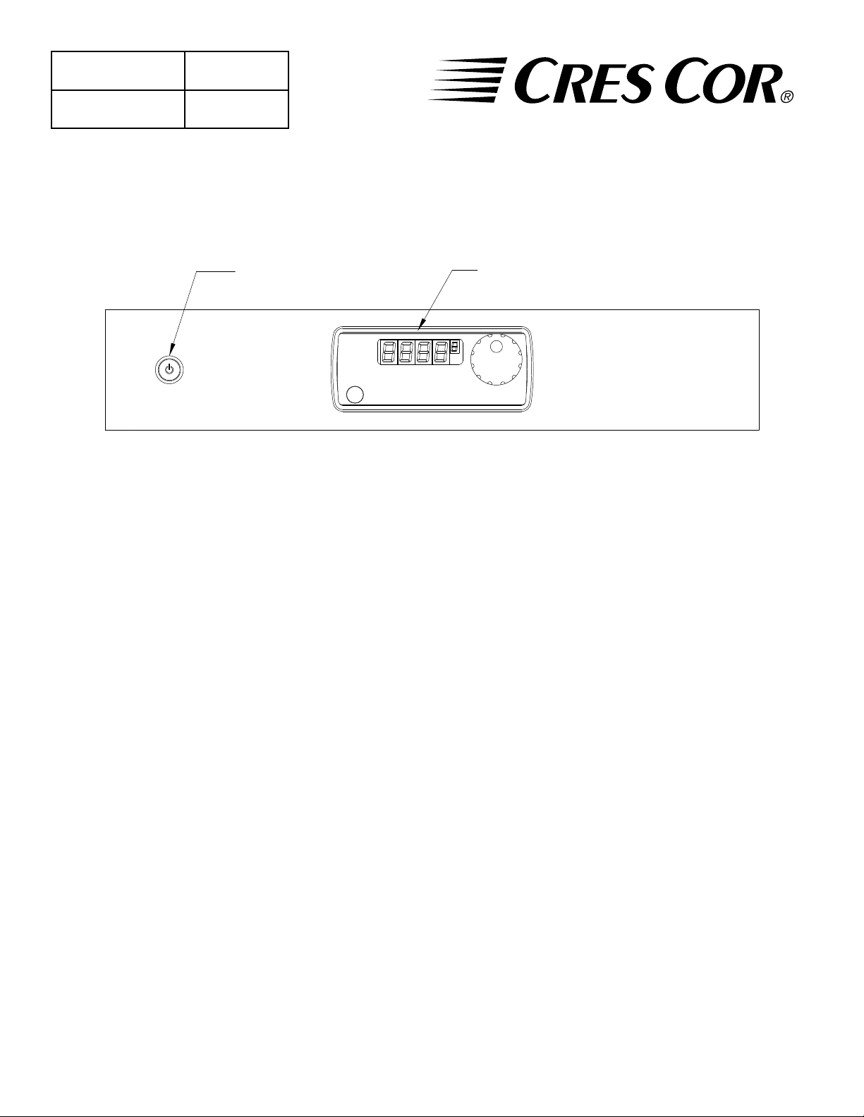
"ON-OFF" SWITCH
DISPLAY
HOW TO INSTALL UNIT:
1. Place cabinet on level oor, in a well ventilated area.
2. Unpack and install inner pan slides parts.
3. Plug cord end into proper wall outlet.
FIRST TIME OPERATION (continued):
1. Push the switch on; the light will come on.
NOTE: The letters “LOTPR” (Low Temperature)
"HOT HOLDING"
DIGITAL CONTROL
will show on the control panel until it reaches
140°F (60°C).
HOW TO CHANGE FROM °C TO °F (if needed)
1. Push the switch on; the light will come on.
2. Push and hold the “SET” button and the button in
the lower left hand corner together for 5 seconds.
You are now entered into the menu.
3. Scroll over the”Unit” and change it to “C” , then
scroll to the “END”.
FIRST TIME OPERATION:
NOTE: A new oven needs to “bur n off” manufacturing
oils and excess adhesive before its rst use.
Do NOT load food into oven until this has
been done!
2. Turn the control knob to show 200°F (93°C).
Push the knob to set the temperature.
Run the unit for one (1) hour.
3. Push the switch off and let cool.
4. Wipe the inside clean with detergent and hot water.
HOW TO START UNIT:
1. Push the switch on; the light will come on.
NOTE: The letters “LOTPR’ will show on the
control panel until it reaches 140°F (60°C).
2. Turn the “Hot Holding” control knob to a temperature
between 140°F (60°C) to 220°F (104°C). Push the
knob to set the temperature.
3. Preheat the cabinet for one (1) hour.
4. Put the food into the cabinet.
NOTE: Press the “Display” button to see the actual
temperature inside the cabinet.
TO TURN OFF UNIT:
Push the POWER switch off; the light will go out.
Call Toll-free: 877-CRES COR (273-7267) • Fax: 800-822-0393 • www.crescor.com
Page 3

Insulated
Hot Cabinet
FL-2354
5925 Heisley Road • Mentor, OH 44060-1833
Rev. 5 (1/13) Page 3 of 5
OPERATING and MAINTENANCE INSTRUCTIONS
Models: H137UA...D & H13818...D Series Hot Cabinets (Aluminum)
H137SUA...D & H138S18...D Series Hot Cabinets (Stainless)
WARNING
BEFORE CLEANING CABINET:
1. Allow the cabinet to cool.
2. Do NOT use abrasives or harsh chemicals.
Is your cabinet aluminum or stainless steel
construction? Be sure your cleaner is suitable
for that material.
Note: Stainless Steel cabinets have an “S” in their
model numbers.
HOW TO CLEAN THE UNIT:
Soil Cleaner Method
Mild Detergent* and hot water, or
mild abrasive cleaner.
Dirt
Steam (no strong alkaline additive)
Mild abrasive cleaner.
Oily or waxy cleaner.
Fingerprints, grease, oil
Chemical oven cleaner.
Cleaning hints:
1. Wipe up spills as soon as possible.
2. Clean cabinet regularly to avoid heavy dirt build-up.
3. Make a test spot with cleaner.
4. Follow manufacturer’s directions on cleaner.
5. Do not mix cleaners.
6. Avoid drips and splashes.
7. Do not use “Cres Clean” on plastic parts or labels.
1. Wipe with soft, damp cloth.
2. Rinse with hot water.
3. Wipe Dry.
1. Rinse after steam cleaning.
2. Wipe Dry
Apply with soft, clean cloth.
Follow oven cleaner manufacturer’s
instructions
Water Spots Mild abrasive cleaner.
*Mild detergent includes soaps and non-abrasive cleaners.
1. Apply with soft, clean cloth.
2. Wipe with damp cloth.
Note: Gaskets are removable for cleaning.
TROUBLE-SHOOTING CHART:
FAILURE: POSSIBLE CAUSE:
1. Switch light or control display does NOT
light up.
2. Unit gets too hot or won’t shut off. 2a. Relay or control defective.
3. Unit does not heat. 3. Defective heater, relay, blower or control.
4. Thermostat control reads “err oo” 4. Temperature probe defective.
1a. Circuit breaker/fuse to wall outlet is blown
1b. Cord is unplugged from wall outlet.
1c. Switch is “OFF.”
1d. Switch or control defective.
UNPLUG UNIT FROM WALL OUTLET
Call Toll-free: 877-CRES COR (273-7267) • Fax: 800-822-0393 • www.crescor.com
Page 4

Insulated
Hot Cabinet
FL-2354
Rev. 5 (1/13) Page 4 of 5
5925 Heisley Road • Mentor, OH 44060-1833
OPERATING and MAINTENANCE INSTRUCTIONS
Models: H137UA...D & H13818...D Series Hot Cabinets (Aluminum)
H137SUA...D & H138S18...D Series Hot Cabinets (Stainless)
REPLACEMENT PARTS: H137UA…D/H1381834D and H137SUA…D/H138S1834D
120 V 208 V 240 V
Blower Kit 0769-180-K 0769-182-K 0769-182-K
Heater Kit 2000W 0811-022-K 0811-185-K 0811-023-K
1500W 0811-019-K 0811-020-01-K 0811-020-K
1000W 0811-214-K 0811-250 0811-215
High Limit 0848-033 0848-033 0848-033
Power Cord 2000W 0810-065-12-K 0810-039-07 0810-039-07
1500W 0810-029-06 0810-039-07 0810-039-07
1000W 0810-029-06 0810-039-07 0810-039-07
Relay, Solid State 0857-136 0857-136 0857-136
Switch, Power 0808-125 0808-125 0808-125
Thermostat Control (Hot) 0848-092-01-K 0848-092-01-K 0848-092-01-K
Thermostat Probe 0848-091-K 0848-091-K 0848-091-K
Terminal Block 0852-119 0852-119 0852-119
Transformer 0769-197 0769-197 0769-197
Vent Fan 0769-165 0769-174 0769-174
Door, complete Aluminum UA12/UA6/1834 1221-578-K
Aluminum UA9 1221-599-K
Stainless Steel UA12/UA6/1834 1221-579-K
Stainless Steel UA9 1221-600
Stainless Steel UA5 1221-597
Door, gasket Aluminum UA12/UA6/1834 0861-235-K
Aluminum UA9 0861-236-K
Stainless Steel UA12/UA6/1834 0861-185-K
Stainless Steel UA9 0861-182-K
Stainless Steel UA5 0861-250-K
Door, hinge 0519-087-K
Door Latch 1006-122-01-K
Door Handle 0911-111
Handle, Side Pull 0911-087
Casters, 5” 0569-306-K
Casters, 5” w/Brake 0569-306-BK
Wire Angles ( 2 per kit) 0621-281-K
Pan Rack Insert (-1834 model) 1103-109
Transport Hasp Latch (Aluminum Cabinet) 1246-031-K
(Stainless Cabinet) 1246-038-K
Call Toll-free: 877-CRES COR (273-7267) • Fax: 800-822-0393 • www.crescor.com
Page 5

Insulated
Hot Cabinet
FL-2354
5925 Heisley Road • Mentor, OH 44060-1833
Rev. 5 (1/13) Page 5 of 5
OPERATING and MAINTENANCE INSTRUCTIONS
Models: H137UA...D & H13818...D Series Hot Cabinets (Aluminum)
H137SUA...D & H138S18...D Series Hot Cabinets (Stainless)
WIRING DIAGRAM
AND 2. REPLACE
WITH WIRES 41,
WIRE AS SHOWN:
42, 43, 44 AND
41, 42 TO TB1
43, 44 TO POWER
SWITCH
42
41
FUSES
G
TO HOLD GROUND
*LOCKWASHER AND
NUT (OR DOUBLE
NUTS) IS REQUIRED
TERMINAL TO
GROUND STUD
BLUE/ORANGE
BROWN/BROWN
WHITE/WHITE
BLACK/BLACK
DISCARD WIRES 1
OPTIONAL
44
3A
3A
43
2
1
(TO TERMINAL BLOCK)
POWER SWITCH
L
N
N
L
(REAR VIEW)
3
4
TRANSFORMER WIRING 240V
WHITE/WHITE
BLACK/BLACK
BROWN/BROWN
BLUE/ORANGE
TRANSFORMER
WIRE COLORS: TRIAD/HAMMOND
K2
K1
AIR TEMP
LOOKING AT REAR
K3
RENAU CONTROL
P1
8
16
7
15
6
14
5
13
4
12
3
11
12
11
10
2
10
1
9
9
t°
AIR
PROBE
GREY/RED
RED/YELLOW
YELLOW/GREY
PURPLE/BLUE
10
9
5
4
7
13
L1 T1
A2(-)
A1(+)
2
1
6
13
8
14
12
3
AIR HEATER
SOLID STATE RELAY 1
11
TB1
FAN
VENT
5
6
MOTOR
BLOWER
8
7
16
15
AIR HEATER
HIGH LIMIT 400F
14
*MUST HAVE THERMAL GREASE
OR THERMAL PAD INSTALLED
BETWEEN RELAYS AND
MOUNTING SURFACES
Call Toll-free: 877-CRES COR (273-7267) • Fax: 800-822-0393 • www.crescor.com
 Loading...