

Cree ZR14, ZR24, ZR22 Installation Instructions Manual
ZR Series with Cree SmartCast® Technology
Architectural Troffers with Removable Lens
Includes: ZR14™, ZR22™ and ZR24™
IMPORTANT SAFEGUARDS
When using electrical equipment, basic safety precautions should
always be followed including the following:
READ AND FOLLOW ALL SAFETY
INSTRUCTIONS
1. DANGER- Risk of shock- Disconnect power before installation.
DANGER – Risque de choc – Couper l’alimentation avant l’installation.
2. This luminaire must be installed in accordance with the NEC or your
local electrical code. If you are not familiar with these codes and
requirements, consult a qualied electrician.
Ce produit doit être installé conformément à NEC ou votre code
électrique local. Si vous n’êtes pas familier avec ces codes et ces
exigences, veuillez contacter un électricien qualié.
3. Do not handle energized module with wet hands or when standing on wet
or damp surfaces, or in water.
4. Suitable for damp locations.
Convient aux emplacements humides.
5. Access above ceiling required. Do not install insulation within 3" (76mm) of
any part of the luminaire.
Accès requis au-dessus du plafond. Ne pas mettre l’isolant à moins de 76
mm (3 po) de toute partie du luminaire.
SAVE THESE INSTRUCTIONS FOR
FUTURE REFERENCE
INSTALLATION INSTRUCTIONS
INSTRUCTIONS D’INSTALLATION
ZR14™
ZR22™
• The ZR Series of recessed
troffers is for non-insulated
ceiling applications using
T-Bar ceiling grid, drywall grid
adaptors, and
suspended mount.
• Designed for use in 120277V 50-60 Hz or 347V 60Hz
protected circuit (fuse box,
circuit breaker). Supply wire
sized as per NEC or governing
code(s), 90C rated.
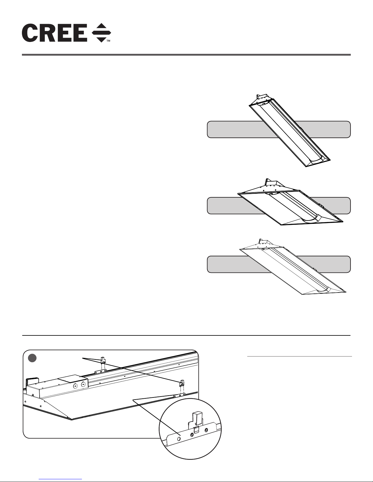
TO INSTALL:
1
T-Bar Clips
• Make sure to cap off all unused
leads.
• ** Not intended for use with
9/16” T-Bar grids unless used
with a 9/16” accessory clip like
“Armstrong® LFC- Fixture Clip”
which can be purchased through
distribution. Consult factory for
non-standard grid applications.
• Lens may shift during
installation. Press center of
lens to engage magnet strip
after installation.
Mounting Bracket
ZR24™
T- BAR CEILING MOUNTING
STEP 1:
Install the (2) supplied T-Bar clips onto the
mounting bracket on the outside of the housing.
See Figure 1.
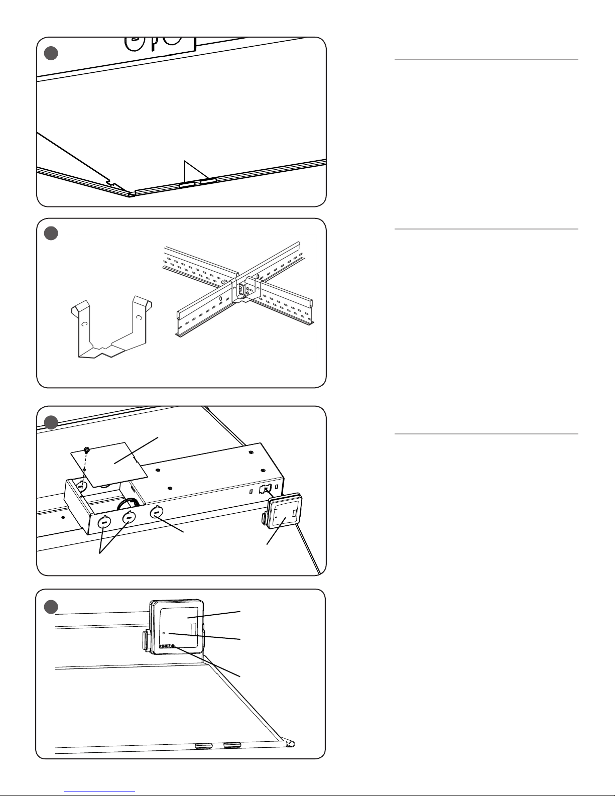
STEP 2:
Bring the ZR troffer into the T-Bar Ceiling panel
and attach the clips on the housing onto the
T-Bar.
STEP 3:
Attach the RF Module to the luminaire by
clicking it into place as Shown in Figure 3.
1 of 4
LPN00467X0003A0_B
2
SUSPENDED MOUNTING
STEP 1:
Attach customer supplied cables to the (2)cable
slots on each corner of the housing. See Figure 2
and 3.
STEP 2:
Attach customer supplied cables to mounting
surface using customer supplied hardware.
Cable Slots
Ensuring that mounting surface can support the
luminaire.
STEP 3:
Attach the RF Module to the luminaire by clicking it
into place as Shown in Figure 4.
RESET RF MODULE
3
NOTE: The Blue LED is located behind the CREE
logo on the RF Module. The CREE logo with
illuminate blue when the Blue LED is active.
STEP 1:
Actuate RESET button through the access hole.
Push and hold until LED on RF module begins
blinking rapidly (approximately 6-7 seconds). See
Figure 5.
STEP 2:
Armstrong® LFC- Fixture Clip to
use for 9/16th applications.
Release for 1 sec.
STEP 3:
Press/Hold RESET button for 0.5 sec. Light will turn
off for a few seconds then go to full bright and the
Blue LED on the RF Module should begin a 2 blink
sequence. Figure 5.
4
Junction Box
Cover
TROUBLESHOOTING:
Out of the box, if the light does not turn on when
power is applied:
• Check Wiring with power off
• If wired correctly, check to see if Blue LED
blinking on the RF Module.
• If Blue LED is blinking, then perform a
RESET
(See RESET RF MODULE section).
Knock-outs
DO NOT use third
Knock-out
RF Module
• If Blue LED is on solid or off, call Cree
Customer Service.
• If you have done a RESET, and the light is
still off, call Cree Customer Service.
If light is unresponsive, use Cree Configuration Tool
to verify configuration.
5
RF Module
Access Hole, Reset Button
Inside
Blue LED
Placement
2 of 4
LPN00467X0003A0_B
 Loading...