

Cree 228 Series, XCTAM Series Installation Instructions Manual

228 SERIES
LED RECESSED UPGRADE KIT LUMINAIRE
INCLUDES: XCTAM SERIES
INSTALLATION INSTRUCTIONS
CAUTIONS
IMPORTANT SAFEGUARDS
When using electrical equipment, basic safety precautions should always be followed including the following:
READ AND FOLLOW ALL SAFETY INSTRUCTIONS
1. DANGER – RISK OF SHOCK – DISCONNECT POWER BEFORE INSTALLATION
DANGER – RISQUE DE CHOC – COUPER L’ALIMENTATION AVANT L’INSTALLATION
2. This LED Upgrade product is UL Classified for use with Elsco Merritt, Whiteway Riviera, LSI Masters/Dakota, Rig-a-Lite, Jet-Philips
or Elsco Franciscan only. DO NOT install into any other manufacturer’s luminaire. To maintain existing Luminaires’ UL listing, the LED
Upgrade Kit must be UL Classified for use with the manufacturer and model of existing luminaire. Consult CREE Customer support to see
if other luminaires are classified to be used with this LED Upgrade Kit.
Ce produit Upgrade LED est classifié UL pour une utilisation avec la série Elsco Merritt, Whiteway Riviera, LSI Masters/Dakota, Rig-a-Lite,
Jet-Philips ou Elsco Franciscan seulement. Ne pas installez ce Upgrade LED dans le luminaire de tout autre fabricant. Pour maintenir la
qualification UL des Luminaires existants, le kit LED Upgrade doit être classifié UL pour une utilisation avec le fabricant et le modèle de
luminaire existant. Consulter CREE Support Clientèle pour voir si les autres luminaires peuvent être utilisés avec ce Upgrade LED.
3. WARNING – Risk of fire or electric shock. LED Upgrade Kit installation requires knowledge of luminaires electrical systems. If not
qualified, do not attempt installation. Product must be installed in accordance with NEC or your local electrical code. If you are not
familiar with these codes and requirements, contact a qualified electrician.
ATTENTION- Risque d’incendie ou de choc électrique. L’installation du kit upgrade LED exige la connaissance des systèmes électriques pour
luminaires. Si non qualifié, ne tentez pas d’installation. Ce produit doit être installé conformément à NEC ou votre code électrique local. Si
vous n’êtes pas familier avec ces codes et ces exigences, veuillez contacter un électricien qualifié.
4. WARNING – Risk of fire or electric shock. Luminaire wiring and electrical parts may be damaged when drilling for installation of the LED
Upgrade Kit. Check for enclosed wiring and components.
ATTENTION - Risque d’incendie ou de choc électrique. Câblage électriques peuvent être endommagés lors du perçage pour l’installation du
kit upgrade LED. Vérifier les fils et composants.
5. WARNING – Risk of fire or electric shock. Check the existing wiring for damage before installing Upgrade Kit. Do not install if existing
wires are damaged.
ATTENTION- Risque d’incendie ou de choc électrique. Vérifiez si le câblage existant n’est pas endommagé avant l’installation du kit upgrade
LED. Ne pas installer si des fils sont endommagés.
6. WARNING – To prevent wiring damage or abrasion, do not expose wires to the edge of sheet metal or any other sharp objects.
ATTENTION - Pour éviter les dégâts de câblage par l’abrasion, ne pas mettre en contact les fils électriques avec des bords de tôle ou
d’autres objets pointus.
7. WARNING – Risk of fire or electric shock. Install this kit only in the luminaires that have the construction features and dimensions shown
in the photographs and/or drawings.
ATTENTION - Risque d’incendie ou de choc électrique. Installez ce kit seulement dans les luminaires qui ont les caractéristiques de
construction et les dimensions dans les photographies ou les dessins de la page suivante.
8. Do not make or alter any holes in a wiring enclosure or electrical components during the kit installation.
Ne pas modifier ou faire de trous dans une boite de câblage ou compartiment électrique lors de l’installation du kit.
9. Ensure that the existing luminaire is installed according to original manufacturer’s specification.
S’assurer que les luminaires sont installés selon les spécifications du fabricant.
10. Only the holes indicated in the photographs or drawings may be made or altered as a result of the kit installation. Do not leave any other
holes open in a wiring enclosure or electrical component.
Seulement les trous indiqués dans les photographies ou les dessins peuvent être faits ou altérés pour l’installation du kit LED. Ne laissez
aucun trou ouvert dans le compartiment électrique.
11. The Upgrade Kit contains a universal LED driver and can be operated at voltages of 120-277V or 347/480V.
Le kit de rénovation contient une alimentation universelle et peut fonctionner à des tensions de 120-277V ou 347/480V.
12. Once the Upgrade Kit is installed, the luminaire can no longer accept HID lamps and shall not be converted back to an HID luminaire.
Une fois le kit upgrade LED installé, l’appareil peut ne plus accepter les lampes HID et ne pourra pas être retransformé en luminaire HID.
SAVE THESE INSTRUCTIONS FOR FUTURE REFERENCE
HOUSING SIZES
NOTE: Ensure the sizes of the existing luminaire housings are
approximately as follows:
Richmond: 21-3/5”L X 12”W X 13-4/5”H
Whiteway Civic: 20-9/10”L X 10-9/10”W X 13-2/5”H
Page 1 of 3
UPGRADE KIT LIST OF COMPONENTS
1. Upgrade assembly 228 Series
2. (2) - Corner mount brackets
3. (2) - Corner mount brackets with suspension cables
4. (4) - Mounting screws
5. (8) - Self-drilling screws
6. (4) - Washers
7. (4) - Retainers
CI372X05R1
F1
F3 F4
SENSOR DOOR
F2
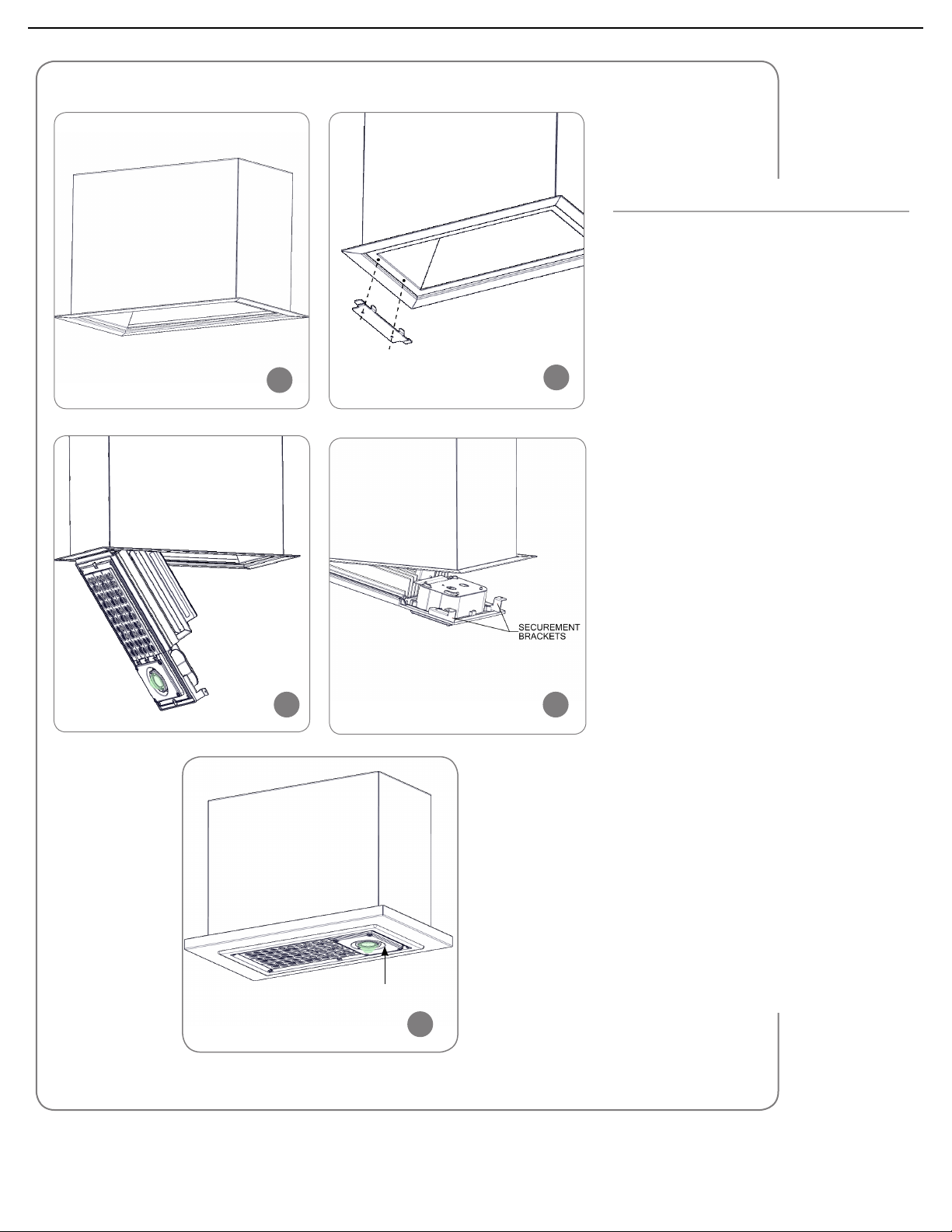
INSTALLATION
STEP 1:
Disconnect power to fixture.
STEP 2:
Verify the existing housing model.
STEP 3:
Open and remove lens frame assembly.
Remove door mounting hardware, lamp,
reflector, ballast cover and socket assembly.
Disconnect incoming power leads.
See Figure 1.
NOTE: Existing ballast and capacitor may
be left in fixture if they do not interfere with
the LED upgrade module and if the existing
luminaire is not supported solely by the j-box.
If removed, components should be recycled
according to all local, state, and/or federal
ordinances.
STEP 4:
Check the caulk between the Canopy and
the existing luminaire housing. Add caulk as
needed to ensure water tight installation.
STEP 5:
Using the supplied self-tapping screws, attach
the Hinge Mounting Bracket to the existing
housing. See Figure 2.
STEP 6:
Hang the fixture by the Mounting Bracket with
Hanging Slot on to the previously installed
Hinge Mounting Bracket. See Figure 3.
STEP 7:
Make wiring connections per the “Electrical
Connections” section.
STEP 8:
After all electrical connections are made,
rotate fixture up and secure in place by
attaching Securement Mounting Brackets to
the fixture housing flange (opposite Hinge
Mounting Bracket) using the supplied selftapping screws.
See Figure 4.
STEP 9:
Attach the Trim Frame over the installed
fixture using the (8) supplied self-tapping
screws.
See Figure 5.
NOTE: If installing into a Whiteway Civic,
install spacer between trim frame and fixture.
STEP 10:
Reconnect power to the fixture.
Page 2 of 3
F5
CI372X05R1
 Loading...