

Cree XA-NEMA, XAL, XAR Installation Instructions Manual
XA-NEMA ACCESSORY KIT
INCLUDES: XAL AND XAR
IMPORTANT SAFEGUARDS
When using electrical equipment, basic safety precautions should always be followed including the following:
INSTALLATION INSTRUCTIONS
READ AND FOLLOW ALL SAFETY INSTRUCTIONS
1. DANGER- Risk of shock- Disconnect power before installation.
DANGER – Risque de choc – Couper l’alimentation avant l’installation.
2. This product must be installed in accordance with the NEC or your local electrical code. If you are not familiar with these codes and requirements,
consult a qualied electrician.
Ce produit doit être installé conformément à NEC ou votre code électrique local. Si vous n’êtes pas familier avec ces codes et ces exigences,
veuillez contacter un électricien qualié.
3. For use with Fixed arm or Adjustable arm mount LED xtures.
SAVE THESE INSTRUCTIONS FOR FUTURE REFERENCE
• Prior to installation, store luminaire in a dry location protected from rain, dust, and outdoor environment. If equipped with a photocell receptacle,
remove the protective cover only if immediately replacing with a suitable photocell, shorting cap, or other compatible device. The protective socket
cover is not intended to remain in place after installation. Do NOT leave receptacle open to environmental elements. Luminaires with a topmounted photocell receptacle should not be installed in an up-light position or at a tilt greater than 45 degrees from the down-light position.
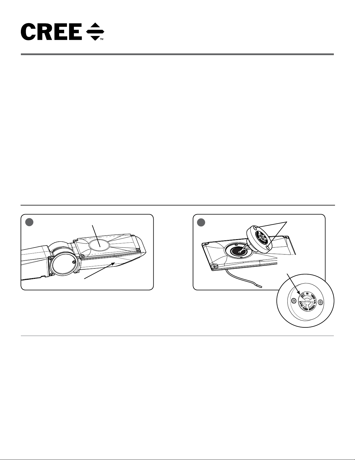
TO INSTALL:
1
Knock Out Hole
2
Insert Screws
Mounting Arm
(Attached to Luminaire)
XANEMA* INSTALLATION/WIRING
STEP 1:
Using a hammer, carefully knock out the hole on the
top of the Mounting Arm Cover. See Figure 1.
STEP 2:
Remove Mounting Arm Cover from the LED
luminaire and set aside the hardware.
STEP 3:
Remove ground wire that is located between Mounting
Arm Cover and luminaire by removing it from the
terminal block in the luminaire mounting arm.
STEP 4:
Remove any metal chips from inside of housing.
STEP 5:
Remove protective cap.
North arrow on
receptacle must
point NORTH on final
installation
STEP 6:
Place Photo Control Receptacle into knock out hole and loosely secure
with two supplied screws. Rotate arrow on receptacle to North and
tighten screws using a Torx T15 bit as shown in Figure 2.
STEP 7:
Wire the Mounting Arm Cover with the Photo Control Receptacle to the
LED Luminaire Arm per “Electrical Connection” section on the back
page.
STEP 8:
Secure Mounting Arm Cover with Photo Control Receptacle to fixture
arm with screws removed from Step 2 ensuring that no wires are
pinched.
NOTE: This fixture is supplied with a surge suppressor, do not
disconnect during the installation process.
1 of 2
CI282X01R2
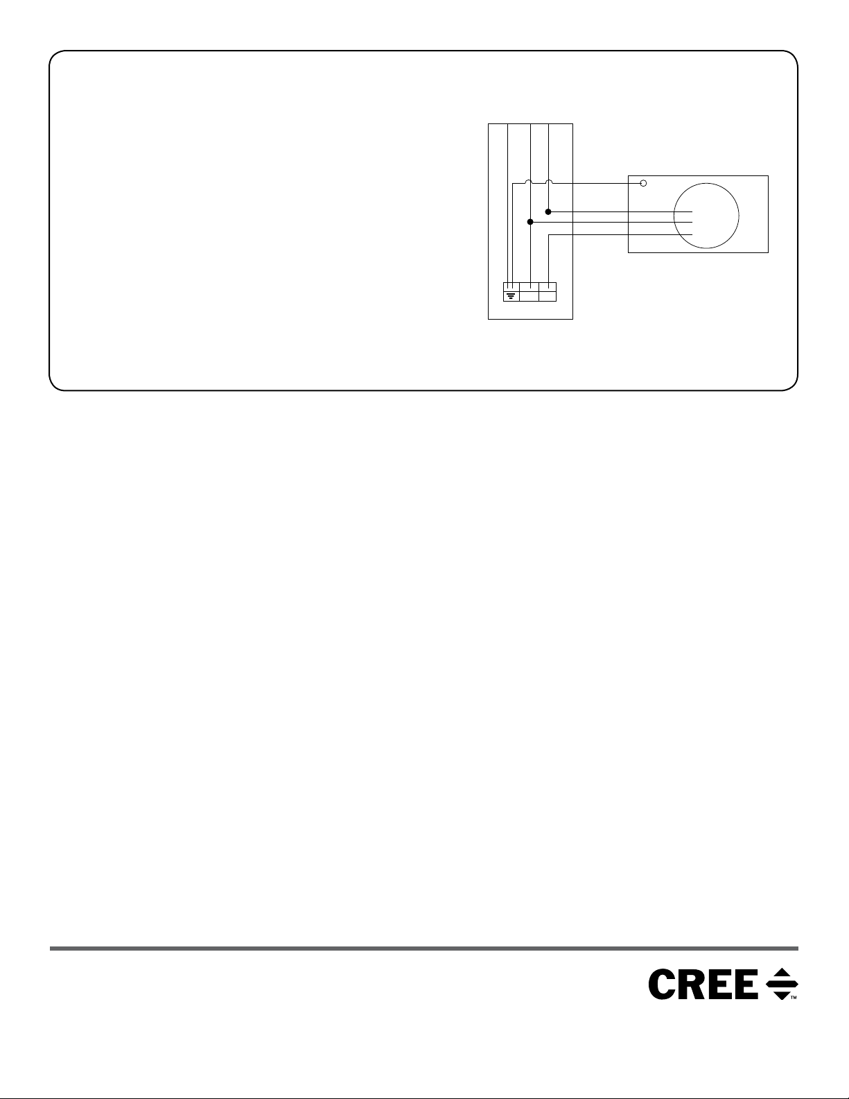
ELECTRICAL CONNECTIONS:
STEP 1:
Make the following electrical connections:
a. Connect ground (green) wire from new mounting arm cover to
the terminal block.
b. Connect black wire from Photo Control Receptacle into
terminal block.
c. Connect the red wire from the Photo Control Receptacle to the
black wire(s) from the fixture using included lever nut.
d. Connect white wire from Photo Control Receptacle to white
wire(s) from fixture and 6” white lead included in the kit with
provided lever nut. Insert the other end of the 6” white wire into
the terminal block.
LED FIXTURE ARM
Green
White
Black
6” White Lead
N L1
TERMINAL BLOCK
Green
Red
White
Black
MOUNTING ARM COVER WITH
PHOTO CONTROL RECEPTACLE
RECEPTACLE
CONTROL
PHOTO
© 2018 Cree, Inc. All rights reserved. For informational purposes only. Content is subject to change.
See http://lighting.cree.com/warranty for warranty and specifications. Cree
trademark of Cree, Inc. NEMA
2 of 2
®
is a registered trademark of the National Electrical Manufacturers Association.
®
is a registered trademark, and the Cree logo is a
www.lighting.cree.com
CI282X01R2
 Loading...