

Cree THE EDGE Series Installation Instructions Manual
THE EDGE
®
LED PARKING STRUCTURE
Surface Mount
When using electrical equipment, basic safety precautions should always be followed
IMPORTANT SAFEGUARDS
including the following:
READ AND FOLLOW ALL SAFETY
INSTRUCTIONS
1. DANGER- Risk of shock- Disconnect power before installation.
DANGER – Risque de choc – Couper l’alimentation avant l’installation.
2. This luminaire must be installed in accordance with the NEC or your
local electrical code. If you are not familiar with these codes and
requirements, consult a qualied electrician.
Ce produit doit être installé conformément à NEC ou votre code
électrique local. Si vous n’êtes pas familier avec ces codes et ces
exigences, veuillez contacter un électricien qualié.
3. When handling, hold xture on sides to prevent damage to the top
screen or LED’s.
4. Take care to keep the LED lenses clean during installation.
5. This xture contains a universal LED driver and can be operated at
voltages of 120V thru 277V.
SAVE THESE INSTRUCTIONS FOR
FUTURE REFERENCE
TO INSTALL:
INSTALLATION INSTRUCTIONS
INSTRUCTIONS D’INSTALLATION
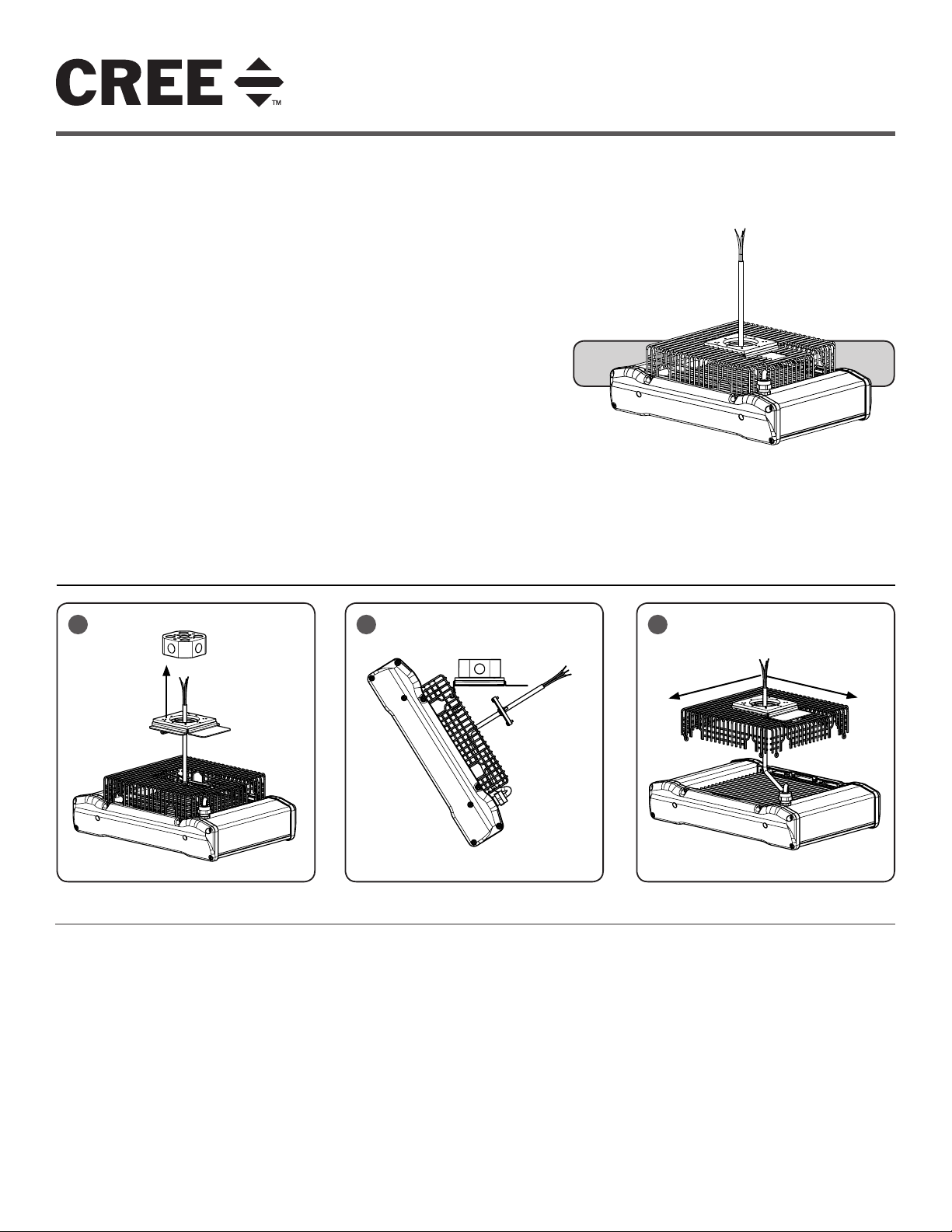
1
MOUNTING- CEILING MOUNT BOX
STEP 1:
Loosen the Phillips head screw holding
the mounting bracket to the fixture cage by
inserting a Phillips screw driver thru the
access hole located on the side
of the fixture cage. Remove bracket.
STEP 2:
Loosen the (2) Phillips head screws holding
the cord plate assembly to the mounting
bracket and remove the bracket.
STEP 3:
Install the mounting bracket to the customer
supplied J-box with the gasket facing the
J-box. Tighten J-box screws firmly. See
Figure 1.
1 of 2
2 3
STEP 4:
Route supply wires thru the mounting
bracket. For ease of installation, hang fixture
on mounting bracket hook. See Figure 2.
NOTE: For some mounting locations that
would prevent the fixture from sliding into the
mounting bracket, the position of the fixture
cage may be changed. See Figure 3. To do
this, remove the (4) screws holding the cage
to the fixture and rotate the cage 90°. Replace
and tighten screws.
STEP 5:
Complete electrical connections as
appropriate. Reference Electrical
Connections section.
STEP 6:
Push excess leads into J-box thru the
mounting bracket and install the cord plate
assembly on the jbox mounting bracket.
Tighten screws firmly.
STEP 7:
Remove the fixture from the hook and slide
the fixture cage over the mounting bracket.
Secure fixture to mounting bracket by
tightening screw removed in Step 1.
CI320X01R1
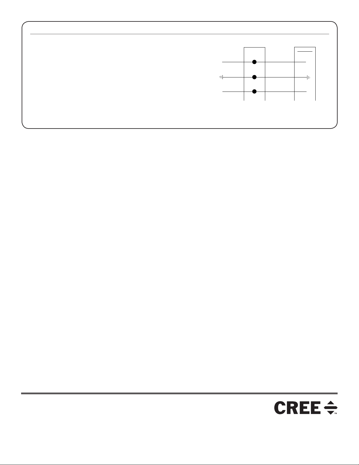
ELECTRICAL CONNECTIONS
LINE
OR HOT 1
GREEN
LINE-BLACK
GROUND-GREEN
NEUTRAL-WHITE
NEUTRAL
OR HOT 2
SUPPLY WIRING
LUMINAIRE
STEP 1:
Make the following Electrical Connections using customer supplied 90°C
minimum rated wire connectors:
a. Connect the black fixture lead to the voltage supply position or Hot 1.
b. Connect the white fixture lead to the neutral supply position or Hot 2
for 208V power supply.
c. Connect the green or green/yellow ground lead to the supply ground
lead.
© 2017 Cree, Inc. All rights reserved. For informational purposes only. Content is subject to change.
See http://lighting.cree.com/warranty for warranty and specifications. Cree® and Edge® are registered trademarks, and the Cree
logo is a trademark of Cree, Inc.
2 of 2
www.lighting.cree.com
CI320X01R1
 Loading...