

Cree RUL Series Installation Instructions Manual
RUL Series
LED Rural Utility Luminaire
When using electrical equipment, basic safety precautions should always be followed
including the following:
READ AND FOLLOW ALL SAFETY
INSTRUCTIONS
IMPORTANT SAFEGUARDS
1. DANGER- Risk of shock- Disconnect power before installation.
DANGER – Risque de choc – Couper l’alimentation avant l’installation.
2. This luminaire must be installed in accordance with the NEC or your local electrical
code. If you are not familiar with these codes and requirements, consult a qualied
electrician.
Ce produit doit être installé conformément à NEC ou votre code électrique local.
Si vous n’êtes pas familier avec ces codes et ces exigences, veuillez contacter un
électricien qualié.
3. If NEMA photo control is installed refer to NEMA® Receptacle section for
instructions.
4. If mounting bolts are completely removed in the eld they should be hand threaded
(prior to use of power tools) to ensure proper engagement of the thread when reinstalling. Failure to pre-start threads may result in cross-threading or stripping of the
bolts during reinstallation.
SAVE THESE INSTRUCTIONS FOR FUTURE
TO INSTALL:
1
2
Mounting Bracket
Bolts
REFERENCE
Cover Tabs
Pole
LUMINAIRE INSTALLATION
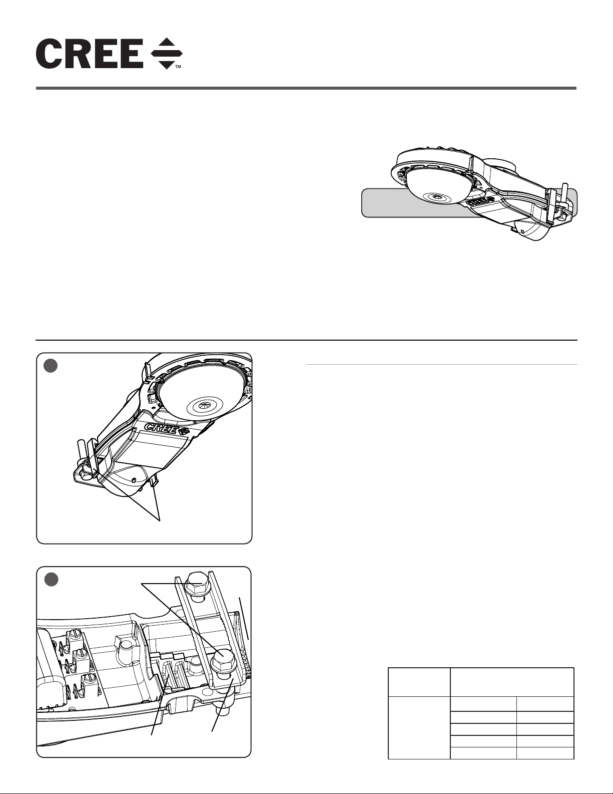
STEP 1:
To open cover, press tabs in on both sides of the cover and carefully let the
cover swing down. See Figure 1.
STEP 2:
Slide fixture on to a 1.66"O.D. or 2.38"O.D. pole tenon or mast arm through
opening on the rear of housing. See Figure 2.
STEP 3:
Adjust leveling of fixture from side to side. To level from front to back, slide
pole to different Adjustment Steps in housing. Each step changes the angle
in 2.5° degree increments.
STEP 4:
Once desired position is achieved, use 9/16" socket wrench to tighten
mounting bolts to 150 in-lbs torque See Figure 2.
STEP 5:
IMPORTANT - DO NOT exceed 300 in-lbs torque on the mount bolts.
Exceeding recommended torque value resulting in excessive deformation of
mounting bracket will cause stripping of mount hardware which could lead
to an unsafe mounting condition.
STEP 6:
Reference Electrical Connections section for completing electrical
connections.
NOTE: Refer to chart below for torque values for the screws on the
terminal block.
STEP 7:
If luminaire has a cord, route the cord down through the pole and make
electrical connections to customer supplied junction box.
INSTALLATION INSTRUCTIONS
INSTRUCTIONS D’INSTALLATION
5ME Optic
Wire Size (AWG) Assigned Torque Value for Screws
AWG In.-lbs.
2-14 Copper, 2-8
Adjustment
Steps
1 of 2 LPN00283X0001A0_E
Mounting
Bracket
Aluminum
2-3 50
4-6 45
8 40
10-14 35
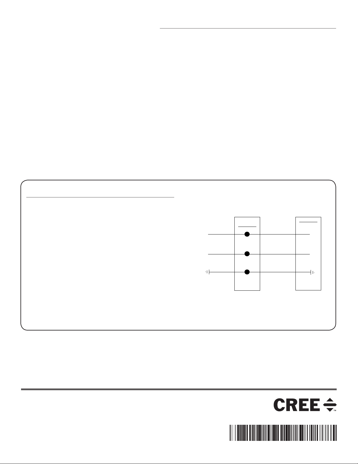
ELECTRICAL CONNECTIONS
LINE
GREEN
LINE-BLACK
GROUND-GREEN
NEUTRAL-WHITE
NEUTRAL
SUPPLY WIRING
LUMINAIRE
TERMINAL
BLOCK
NEMA® RECEPTACLE (OPTIONAL)
STEP 1:
DO NOT loosen/tighten torx screws for the NEMA® receptacle.
STEP 2:
Rotational adjustment of the photo control is tool-less.
STEP 3:
Engage/install photo control into NEMA receptacle on top of the fixture.
STEP 4:
Firmly rotate photo-control with its photo-eye approximately in the ‘N’ north
direction. Some photo-controls operate best somewhere between NW and NE.
PHASE TO NEUTRAL WIRING
STEP 1:
Make the following Electrical Connections to the terminal block:
a. Connect the black fixture lead to the voltage supply position of
the terminal block.
b. Connect the white fixture lead to the neutral supply position of
the terminal block.
c. Connect the green or green/yellow ground lead to the green wire
position of the terminal block.
STEP 2:
Push excess supply wires into pole.
STEP 3:
Close cover, making sure that no wires are pinched and latches are
fully engaged.
© 2015 Cree, Inc. All rights reserved. For informational purposes only. Content is subject to change.
See www.cree.com/lighting/products/warranty for warranty and specifications. Cree® is a registered trademark, and the Cree
logo is a trademark of Cree, Inc. NEMA® is a registered trademark of the National Electrical Manufacturers Association
2 of 2 LPN00283X0001A0_E
www.cree.com/lighting
 Loading...