

Cree RSWL, RSW Series Installation Instructions Manual
RSW Series
LED Street and Area Light
Includes: RSWL
IMPORTANT SAFEGUARDS
When using electrical equipment, basic safety precautions should always be
followed including the following:
READ AND FOLLOW ALL SAFETY
INSTRUCTIONS
1. DANGER- Risk of shock- Disconnect power before installation.
DANGER – Risque de choc – Couper l’alimentation avant l’installation.
2. This luminaire must be installed in accordance with the NEC or your local
electrical code. If you are not familiar with these codes and requirements,
consult a qualied electrician.
Ce produit doit être installé conformément à NEC ou votre code électrique
local. Si vous n’êtes pas familier avec ces codes et ces exigences, veuillez
contacter un électricien qualié.
3. If NEMA
®
photo control is installed refer to NEMA® Receptacle section for
instructions.
4. If mounting bolts are completely removed in the eld they should be hand
threaded (prior to use of power tools) to ensure proper engagement of the
thread when re-installing. Failure to pre-start threads may result in
cross-threading or stripping of the bolts during reinstallation.
SAVE THESE INSTRUCTIONS FOR
FUTURE REFERENCE
TO INSTALL:
INSTALLATION INSTRUCTIONS
Pole
Mounting
Bracket
1
Mounting Bracket Bolts
Adjustment
Steps
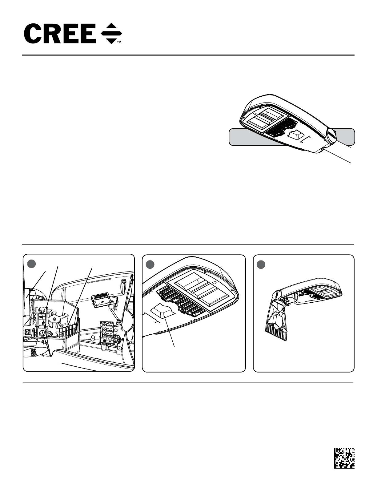
LUMINAIRE INSTALLATION
STEP 1:
Slide fixture on to a minimum 8" tenon,
through opening on the rear of housing. See
Figure 1.
STEP 2:
Once desired position is achieved, open cover
by holding fixture and pulling the handle and
allow the cover to swing open. See Figure 2
and 3.
2
Cover‘s Handle
STEP 3:
To level fixture, use bubble level located
inside housing. Adjust leveling of fixture from
side to side by rotating fixture on pole. To
level from front to back, slide pole in or out
to different step in upper housing. Each step
changes the angle in 2.5 increments
STEP 4:
NOTE: When tightening bolts make sure
to alternate between bolts to keep bracket
straight.
3
Tighten mounting bolts to the appropriate
torque values specified in TORQUE VALUES
table on page 2. See Figure 1 (use 9/16”
socket wrench).
STEP 5:
Reference Electrical Connections section for
completing electrical connections.
1 of 3
LPN00295X0006A0_A
1.66 in O.D.
2.38 in O.D.
4
Pipe
Size
TORQUE VALUES
Pipe Position
+5.0 degrees tilt 200 +/-30 23 +/-3
+2.5 degrees tilt 200 +/-30 23 +/-3
0 degrees (no tilt) 200 +/-30 23 +/-3
-2.5 degrees tilt 200 +/-30 23 +/-3
-5.0 degrees tilt 200 +/-30 23 +/-3
+5.0 degrees tilt 200 +/-30 23 +/-3
+2.5 degrees tilt 200 +/-30 23 +/-3
0 degrees (no tilt) 200 +/-30 23 +/-3
-2.5 degrees tilt 200 +/-30 23 +/-3
-5.0 degrees tilt 200 +/-30 23 +/-3
Bolt Torque
Required (in-lbs)
Bolt Torque
Required (N-m)
NEMA® RECEPTACLE
NOTE: Dimming capabilities are accessible
through the NEMA
®
receptacle when used with a
photo control with dimming capabilities.
STEP 1:
Rotational adjustment of the photo control is tool-less.
STEP 2:
Engage/install photo control into NEMA receptacle on
top of the fixture. If no photo control will be used with
luminaire install customer supplied shorting plug into
receptacle.
STEP 3:
Firmly rotate photo-control with its photo-eye
approximately in the ‘N’ north direction. Some photocontrols operate best somewhere between NW and NE.
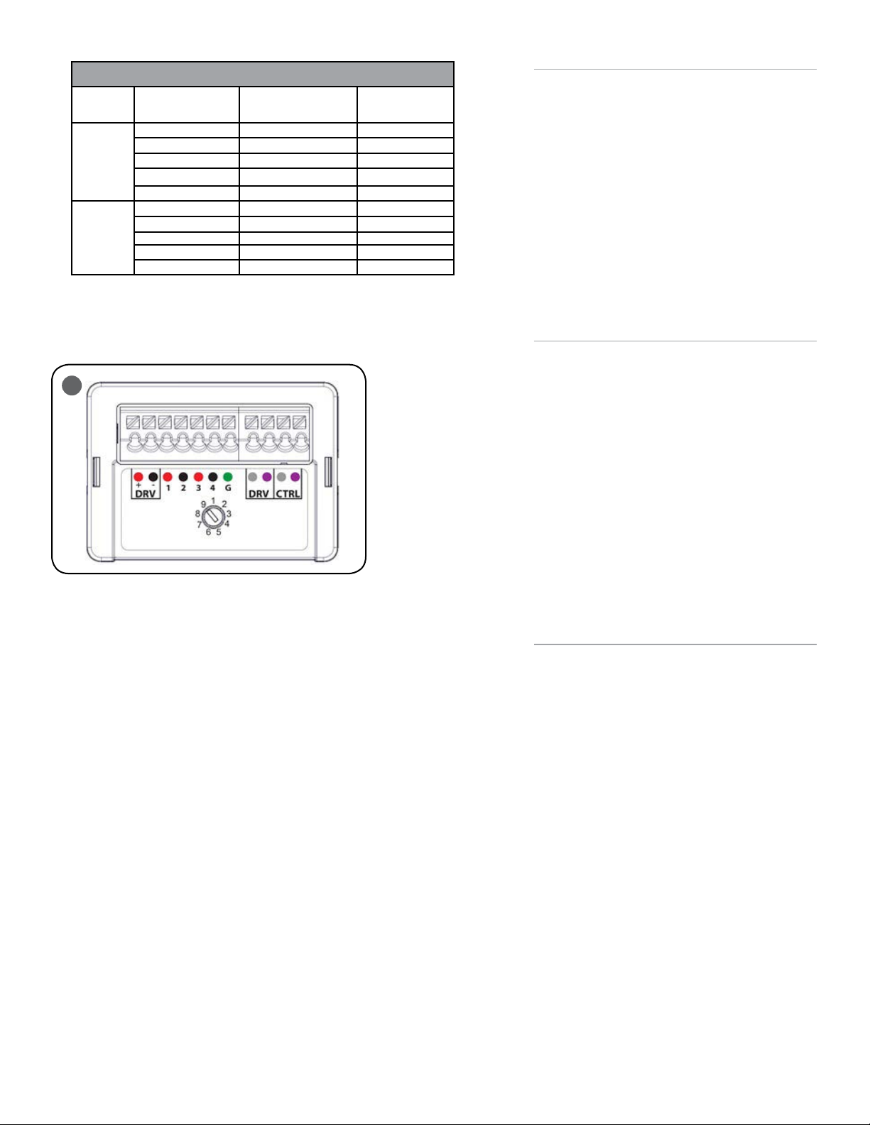
FIELD ADJUSTABLE OUTPUT (OPTIONAL)
NOTE: When ordered with the Q9/Q8/Q7/Q6/Q5/Q4/Q3/
Q2/Q1 Field Adjustable Output Option, this luminaire
includes an internal field adjustable output module,
and ships from the factory at the field adjustable output
setting selected. Refer to the spec sheet for power and
lumen values for each of the settings.
STEP 1:
The Field Adjustable Output module is located inside
the luminaire. Open the cover by holding luminaire and
pulling the handle. Allow the cover to swing open.
STEP 2:
Establish the desired input power or lumen output by
referring to the product spec sheet and turn the switch
to the correlating position. See Figure 4.
STEP 3:
Close the cover ensuring no wires are pinched.
FCC NOTICE
CAUTION: Changes or modifications not expressly
approved could void your authority to use this
equipment.
This device complies with part 15 of the FCC Rules.
Operation is subject to the following two conditions: (1)
This device may not cause harmful interference, and
(2) this device must accept any interference received,
including interference that may cause undesired
operation.
This equipment has been tested and found to comply
with the limits for a Class A digital device, pursuant
to part 15 of the FCC Rules. These limits are designed
to provide reasonable protection against harmful
interference when the equipment is operated in a
commercial environment. This equipment generates,
uses, and can radiate radio frequency energy and, if not
installed and used in accordance with the instruction
manual, may cause harmful interference to radio
communications. Operation of this equipment in a
residential area is likely to cause harmful interference
in which case the user will be required to correct the
interference at his own expense.
CAN ICES-003 (A)/NMB-003 (A)
2 of 3
LPN00295X0006A0_A
 Loading...