

Page 1
Installation and Operating Instructions
Downflow Fan Heater
Model : CDF2IPX4
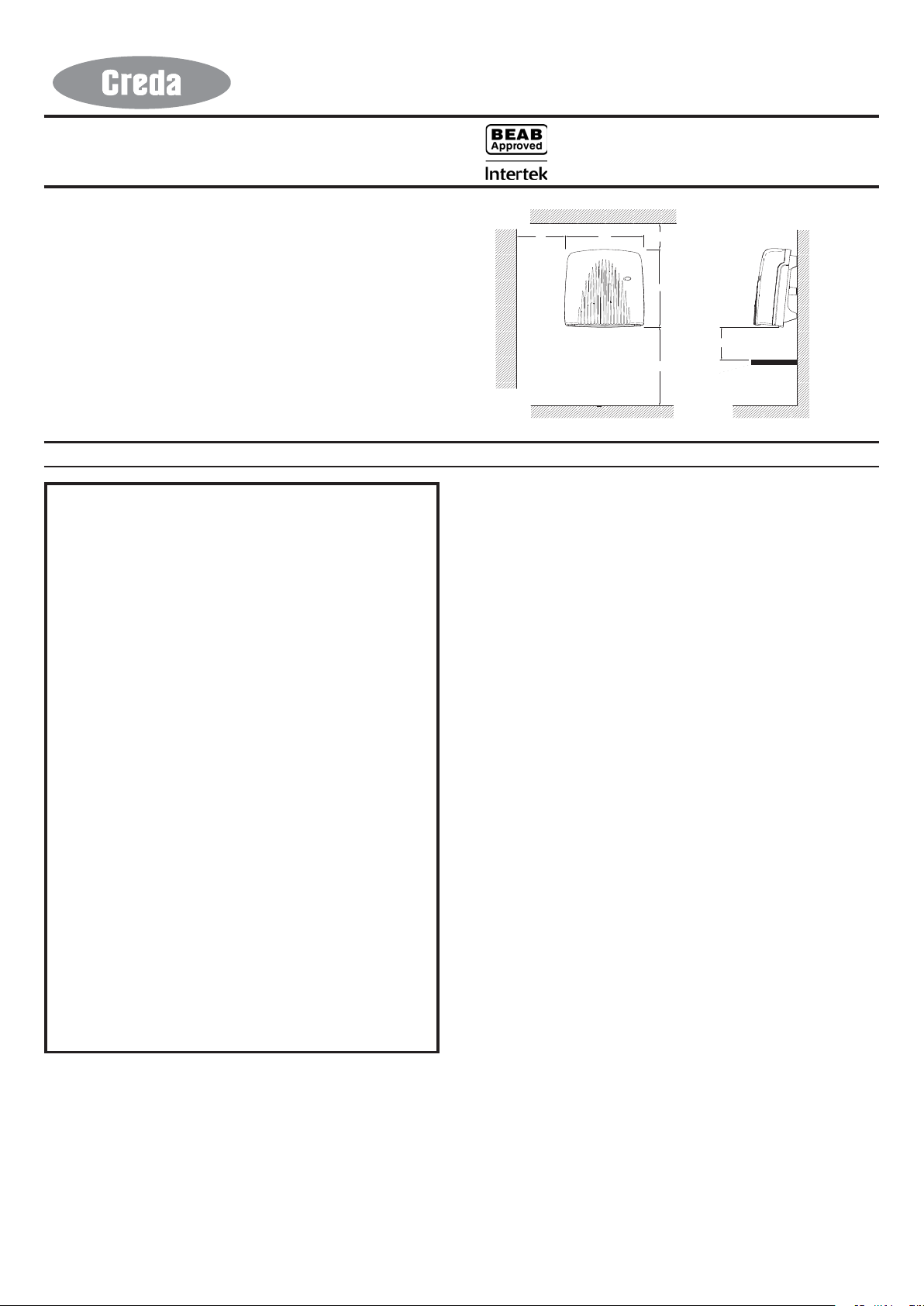
Dimensions
(millimetres)
Model(s) Specification
CDF 2IPX4 (High Level) 1/2kw + Adjustable Thermostat (internal by installer)
THESE INSTRUCTIONS SHOULD BE READ CAREFULLY AND RETAINED FOR FUTURE REFERENCE
IMPORT ANT SAFETY ADVICE
WARNING - DO NOT USE THIS HEATER IN THE IMMEDIATE
SURROUNDINGS OF A BATH, A SHOWER OR A SWIMMING POOL.
DO NOT COVER THE APPLIANCE or place material or
garments on it, or obstruct the air circulation around this
appliance, for example with curtains or furniture, as this
could cause overheating and a fire risk.
DO NOT PLACE AEROSOLS OR OTHER CONTAINERS
SUSCEPTIBLE TO HEA T IN THE DIRECT AIRFLOW FROM THE
UNIT.
THIS HEATER MUST NOT BE LOCATED IMMEDIA TEL Y BELOW
A FIXED SOCKET OUTLET.
This heater must be installed so that the switches and
other controls cannot be touched by the person in the bath
or shower
The appliance is not intended for use by children or other
persons without assistance or supervision if their physical,
sensory or mental capabilities prevent them from using it
safely. Children should be supervised to ensure that they
do not play with the appliance.
WARNING – DISCONNECT THE HEA TER FROM THE ELECTRICITY
SUPPL Y BEFORE UNDERT AKING SERVICE OR REP AIR.
WARNING – If the appliance is fitted in a bathroom, a cable
outlet will be necessary with the supply to the unit
controlled by a double pole switch. The switch if inside
the bathroom should be pull cord operated and if outside
should be adjacent to the entrance door. The appliance
must be mounted so that no part of it can be touched by
any person using bath or shower.
THIS HEATER MUST NOT BE OPERA TED WITHOUT THE COVER
CORRECTL Y IN POSITION.
Warning : In order to avoid a hazard due to inadvertent
resetting of the thermal cutout, this appliance must not be
supplied through an external switching device, such as a
timer, or connected to a circuit that is regularly switched
on and off by the utility.
General
The heater has a loading of 2KW. It is designed for permanent wall mounting
and is suitable for operation on A.C. electricity supply having the same
voltage as shown on the rating label.
The heater is fitted with an internally mounted selector switch which on
installation of the heater allows a choice of 1kW or 2kW output to suit the
dimensions of the room to be heated.
In rooms of less than 9 – 11 cubic m. (350 - 400 cubic ft.) 1kW output should
be selected, otherwise nuisance tripping of the thermal overload cut-out
may occur.
NOTE : THE SWITCH HAS BEEN FACTORY SET FOR 2kW OPERATION.
08/35411/1 Issue 1
(IP24)
&HLOLQJ
0,1
SUPPLY CABLE IS NOT SUPPLIED WITH THIS APPLIANCE AND IT
SHOULD THEREFORE BE INSTALLED BY A COMPETENT ELECTRICIAN
IN ACCORDANCE WITH THE IEE REGULA TIONS.
)ORRU
Controls
The cut-out is a safety device which switches off the heater and fan if for
any reason the appliance overheats - see ‘Safety’.
The thermal fuse link is provided as an added safety feature, and operates
to open circuit if there is abnormal overheating within the appliance. The
operation of these safety devices is described under ‘Safety’
The pull cord switch operates the ON/OFF switch. (An indicator light
illuminates to show when the heater is ON and does not illuminate when
the heater is OFF) .
The heater is fitted with an adjustable thermostat, which has three different
settings : 1. - Low, 2. - Medium, 3 - High. This gives you an approximate
room temperature range of 18°C - 32°C depending on room size. The
temperature switches to half heat when the room warms up. Full heat will
be switched on automatically when the room temperature falls. This can
be adjusted by installer, by removing top cover. The thermostat will only
function when 2KW is selected. The thermostat has been factory set on ‘2’
(Medium).
To adjust the thermostat setting or reset selector switch first remove the top
cover, then adjust thermostat to required setting, or reset selector switch to
1kW or 2kW as required, then refit top cover.
Safety
Cut-Out
For your safety, this appliance is fitted with a thermal cut-out. In the event
that the product overheats, the cut-out switches the heater off automatically.
To bring the heater back into operation, remove the cause of overheating,
then turn off the electrical supply to the heater for a few minutes.
When the heater has cooled sufficiently reconnect and switch on the heater.
Fuse Link
A thermal fuse link is provided as an added safety feature. If the fuse link
operates and opens circuit it is the result of abnormal overheating within
the appliance, and servicing of the appliance by a competent service
engineer will be required in order to ensure the future safe operation of the
heater. Dimplex Customer Services should be contacted, who will arrange
the replacement of any faulty parts and the fitting of a new fuse link.
Installation
Before undertaking installation work, ensure the electricity supply is
disconnected from any relevant fixed wiring. Supply cable is not supplied
with this appliance and it should therefore be installed by a competent
electrician in accordance with the IEE wiring regulations.
The supply circuit must be adequate for the input of the appliance and
must be protected with a 13A fuse.
A suitable termination to the fixed wiring of the premises must be provided
adjacent to the final position of the appliance through a double pole
switch having a contact separation of at least 3mm in all poles.
0,1
0,1
0,1
6KHOI
Fig. 1
Page 2
Installation Procedure
Fig. 2
It is essential to observe minimum wall mounting clearances - see Fig. 1.
The appliance should be fitted horizontally, with the cable entry at the top
and grille at the bottom. It must be mounted not less than 1800mm above
the floor with a clearance of at least 600mm to any shelf or projecting
surface below the heater and not less than 300mm below the ceiling or
other projecting surface. It must also be not less than 250mm from an
adjacent projecting surface. For most effective heating performance, the
heater should be mounted at the minimum height :-
i.e. - 1800mm above the floor.
Care must be taken to ensure that when in use, the air stream is not
obstructed by a high shelf or cabinet.
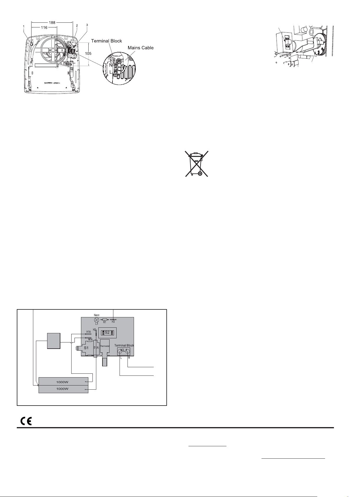
The appliance is secured to the wall with three screws, two through
keyhole slots ‘1’ & ‘3’ and one through a hole ‘2’ to hold the appliance
firmly in position (see Fig. 2).
1. Remove the top cover from the appliance by removing the two
screws securing the top cover and hinging it back.
2. Mark the position of the two keyhole slots ‘1’ & ‘3’ (see Fig. 2 for
dimensions) on the wall and drill and plug for the two suitable
screws.
3. Partially insert the two screws, then hang the appliance on these
screws. Mark the position of the third hole. this is used to secure the
product.
4. Remove the appliance and drill and plug for the third screw.
5. Remount the appliance on the wall using the two keyhole slots.
6. Feed the supply cord or wires through the inlet at the top rear of the
appliance leaving sufficient free length to connect to the terminal
block.
7. Make electrical connections to the terminal block ensuring that the
live connection is made to the terminal marked ‘L’ and the neutral
connection to the terminal marked ‘N’ (see Fig. 2 exploded view).
8. Fix the product inplace by inserting and tightening the third screw.
Fix mains cable securly using the products cable clamp
9. Set the selector switch to provide either 1kW or 2kW output.
10. Replace the top cover and screws.
The appliance is now ready for use and the electricity supply can be
reinstated.
CDF2IPX4 Controls
The heater is fitted with a pull cord
operated ON/OFF switch, a thermostat, a
cut-out, and a thermal fuse link.The
heater has an internal adjustable
thermostat which can be adjusted by
installer (i.e. the top cover has to be
removed), see Fig. 4 for controls details
with cover removed. Temp. range 18°C 32°C.
selector
switch
N
L
internal adjustable
thermostat knob
Fig. 4
Cleaning and User Maintenance
WARNING: BEFORE UNDERT AKING CLEANING OR MAINTENANCE WORK
ON THE APPLIANCE IMMEDIATELY DISCONNECT THE ELECTRICITY
SUPPL Y BY SWITCHING OFF AT THE ADJACENT DOUBLE POLE SWITCH.
The outside can be cleaned by wiping it over with a soft damp cloth and
then dried. Do not use abrasive cleaning powders or furniture polish as this
can damage the surface finish.
Ensure that dust or fluff does not accumulate inside the heater as this could
lead to overheating of the element. Use a vacuum cleaner to remove any
fluff which does accumulate.
Recycling
For electrical products sold within the European Community.
At the end of the electrical products useful life it should not
be disposed of with household waste. Please recycle where
facilities exist. Check with your Local Authority or retailer for
recycling advice in your country.
After Sales Service
Your product is guaranteed for one year from the date of purchase.
Within this period, we undertake to repair or exchange this product free of
charge subject to availability provided it has been installed and operated
in accordance with these instructions.
Your rights under this guarantee are additional to your statutory rights,
which in turn are not affected by this guarantee.
Should you require after sales service you should contact our customer
services help desk.It would assist us if you can quote the model number,
series, date of purchase, and nature of the fault at the time of your call.
The customer services help desk will also be able to advise you should you
need to purchase any spares.
Please do not return a faulty product to us in the first instance as this may
result in loss or damage and delay in providing you with a satisfactory
service.
Please retain your receipt as proof of purchase.
M
Fig. 3 - CDF2IPX4 Wiring Diagram
The product complies with the European Safety Standards EN60335-2-30 and the European Standard Electromagnetic Compatibility (EMC) EN55014,
EN60555-2 and EN60555-3. These cover the essential requirements of EEC Directives 2006/95/EC and 2004/108/EC
CREDA HEATING
MILLBROOK HOUSE
GRANGE DRIVE
HEDGE END
SOUTHAMPTON
SO30 2DF
UK customer help line
Customer Services TEL: 0 845 604 239 9
FAX: 01489 773064
WEBSITE: WWW.CREDAHEATING.CO.UK
Republic of Ireland Tel: 01 842 4833
[c] GDC Group Ltd,
All rights reserved. Material contained in this publication may not be reproduced in whole or in part, without prior permission in writing of GDC Group Ltd..
 Loading...