

Page 1

Getting Started
Quick Start for INTERNETed Audio Tools
Plug and Play Install Tips
Notes for WaveSynth/WG Users
®
with Advanced WavEffects Synthesis
and Creative WaveSynth/WG
TM
Sound
Page 2

Getting Started
Information in this document is subject to change without notice and does not represent a
commitment on the part of Creative Technology Ltd. The software described in this document
is furnished under a license agreement and may be used or copied only in accordance with the
terms of the license agreement. It is against the law to copy the software on any other medium
except as spe cifica lly allowed in the l icense agre ement. The licensee may make one copy of the
software for backup purposes. No part of this manual may be reproduced or transmitted in any
form or by any means, electronic or mechanical, including photocopying and recording, for any
purpose without the written permission of Creative Technology Ltd.
Copyright 1996 by Creative Technology Ltd. All rights reserved.
Version 1.01
November 1996
Sound Blaster is a registered trademark of Creative Technology Ltd.
Sound Blaster 16 and Wave Blaster are trademarks of Creative Technology Ltd.
IBM is a registered trademark of International Business Machines Corporation.
MS-DOS, Windows, and the Windows logo are registered trademarks of Microsoft
Corporation.The hardware on your card is covered by one or more of the following U.S. Patents:
4,404,529; 4,506,579; 4,699,038; 4,987,600; 5,013,105; 5,072,645; 5,111,727; 5,144,676;
5,170,369; 5,248,845; 5,298,671; 5,303,309; 5,317,104; 5,342,990;090,783;4,649,783.
Page 3

Compliance
This product conforms to the following Council Directive:
❑ Directive 89/336/EEC, 92/31/EEC (EMC)
Page 4

Conten t s
Introduction...................... ... .. ..... .. ... .. .. ..... ... .. .. ..... .. ... .. ..... .. ... .. .. ..... .. ... .. ..... .. ...vii
Before You Begin............ ... .. ..... .. ... .. ..... .. ... .. ..... .. .. ... ..... .. .. ... .... ... .. .. ..... ... .. .. ..viii
Checking Syste m Requir e ments........ ... .. ..... .. ... .. ..... .. .. ... .... ... .. ... .... ..viii
Using This Guide...............................................................................viii
Getting More Information........................................................ ...........ix
Document Conventions................................................ ... ....................ix
Text Conventions............ ..... ....... ..... ....... ..... ....... .... ........ .... ....ix
Icons............ .. ... .. .. ... .. .. ... .. ... .. .. ... .. .. ... .. ..... .. ... .. .. ... .. .. ... .. ... .. .. ... ..x
1 Setting Up Your Audio Card
Knowing Your Audio Card................................. .................................... ......1-2
Installing the Card and Related Hardware....................................................1-4
2 Installing Software in Windows 95
Setting Up the Audio Card Drivers......... ........................ ..............................2-1
Installing the App licatio ns....... .. .. ..... .. ... .. ..... .. ... .. ..... .. ... .. ..... .. .. ... .... ... .. ... .... ..2-3
Testing the In stall ation ... .. ... .. ..... .. ... .. ..... .. ... .. ..... .. .. ... ..... .. .. ... .... ... .. .. ..... ... .. .. ..2-3
Uninstallin g the Applications............. ...........................................................2-5
3 Installing Software in DOS/Windows 3.1x
Installing the Sof twar e............. .. .. ..... .. ... .. ..... .. ... .. ..... .. ... .. ..... .. .. ... .... ... .. ... .... ..3-1
Testing the In stall ation ... .. ... .. ..... .. ... .. ..... .. ... .. ..... .. .. ... ..... .. .. ... .... ... .. .. ..... ... .. .. ..3-2
Optimizin g Memory Usage............................... ................................... .........3-3
Using Memor y Managers ........................................................ .........3-3
Bypassing the Loading of the Low-Level Drivers...... ............ .........3-3
v
Page 5

Appendi ces
A General Specifications
B Understanding the Installation
Understanding the Software-Configurable Settings........ ... .. .. ... .. .. ... .. .. ... .. ..B-1
Input/Output (I/O) Addresses.......... .. ... .. .. ... .. ............ .. ... .. .. ... .. .. ... .. ..B-2
Interrupt Request (IRQ) Lines .......... ... .. .. ... .. .. ... .. ... .. .. ... .. .. ... .. .. ... .. ..B-3
Direct Memory Access (DMA) Channels.............. .. ............ .. .. ... .. ..B-3
Understanding the Environment Variables........ .. ... .. .. ... .. ... .. .. ... .. .. ... .. .. ... .. ..B-3
SOUND Environment Variable........... .. ............ .. ... .. .. ... .. .. ... .. .. ... .. ..B-4
BLASTER Environment Variable......... .. ... .. .. ... .. ... .. .. ... .. .. ... .. .. ... .. ..B-4
MIDI Environment Variable............................................................B-5
Understanding the Installation Program in Windows 3.1x......... .. ... .. .. ... .. ..B-5
The AUTOEXEC.BAT File Settings..............................................B-6
The CONFIG .SYS File Settings.................................................... ..B-7
C Chan gin g Au di o Car d Se tti ngs
Enabling/Disabling Creative 3D Stereo Enhancement Effect....................C-1
In Windows 95.............. .. ... .. .. ... .. .. ... ............ .. .. ... .. ... .. .. ... .. .. ... .. .. ... .. ..C-1
In MS-DOS/Windows 3.1x............. .. ... ........... ... .. ... .. .. ... .. .. ... .. .. ... .. ..C-2
Enabling/Disabling Full Duplex Ope ration.................................................C-2
In Windows 95.............. .. ... .. .. ... .. .. ... ............ .. .. ... .. ... .. .. ... .. .. ... .. .. ... .. ..C-3
In Windows 3.1x........... .. ... .. .. ... .. .. ... .. ... .. .. ... .. .. ... .. ... .. .. ... .. .. ... .. .. ... .. ..C-3
Enabling/Disabling MPU-401 MIDI Emulation........ ... .. ... .. .. ... .. .. ... .. .. ... .. ..C-3
In Windows 95.............. .. ... .. .. ... .. .. ... ............ .. .. ... .. ... .. .. ... .. .. ... .. .. ... .. ..C-4
In MS-DOS/Windows 3.1x............. .. ... ........... ... .. ... .. .. ... .. .. ... .. .. ... .. ..C-4
Enabling/Disabling Joystick Interface..... ... .. ... .. .. ... .. .. ... .. ... .. .. ... .. .. ... .. .. ... .. ..C-5
In Windows 95.............. .. ... .. .. ... .. .. ... ............ .. .. ... .. ... .. .. ... .. .. ... .. .. ... .. ..C-5
In MS-DOS/Windows 3.1x............. .. ... ........... ... .. ... .. .. ... .. .. ... .. .. ... .. ..C-6
D Troubleshootin g
Problems Installing Audio Card Software from CD-ROM........................D-1
Problems with Sound....................................................................................D-2
Problems in MS-DOS...................................................................................D-3
Problems in Windows 3.1x...........................................................................D-4
Resolving Conflicts......... ... .. .. ... .. ... .. .. ... .. .. ... .. ... .. .. ... .... ... .. ... .. .. ... .. .. ... .. .. ... .. ..D-5
Resolving Conflicts in Windows 95................................................D-6
Resolving Conflicts in MS -DOS/Windows 3.1x............................D-6
vi
Page 6

Introduction
Welcome to the exciting world of Advanced WavEffects synthesis!
®
You are now the owner of a Creative Sound Blaster
AWE64 Gold, a
16-bit audio card, which comes with the state-of-the-art Creative
WaveSynth/WG software.
Your Sound Blaster AWE64 Gold audio card allows you to achieve
realistic and three-dimensional (3D) acoustic reproduction through a
wide range of digitized sound samples and Creative 3D Stereo
Enhancement technology.
Fully Sound Blaster compatible, your AWE64 Gold audio card
supports the following features:
❑ Plug and Play ISA Specification version 1.0a complianc e
❑ Major MIDI standards such as General MIDI, Roland GS and
MT-32
❑ Compression algorithms such as A-law, Mu-law, CTADPCM,
and IMA-ADPCM
❑ Full duplex operation for simultaneous audio recordin g and
playback
Creative WaveSynth/WG employs the latest technologies for sound
creation and playback in persona l computer softwa re: sample -base d
wavetable synthesis (WaveSynth) and ph ysical model-based
waveguide (WG) synthesis.
With your AWE64 Gold audio card installed in an Intel Pentium 90
MHz (or higher) computer, the sample - based waveta ble synthesizer
allows you to play high quality music and sound effects via software
(instead of hardware) in any Windows-based multimedia applicatio n.
It also has a physical model-based waveguide synthesizer which uses
®
Sondius
Sound Synthesis technology to enable you to play
waveguide sounds polyphonically and multi-timbrally. In other
words, you can play m any notes and different instruments or sound
effects at the same time. WaveSynth/WG is also a General MIDI
synthesizer that acts like a multi-channel mixer with high quality
reverb.
vii
Page 7

If you do not want to use WaveSynth/WG, you can disable it through
the WaveSynth/WG Control Panel. Then, your MIDI and audio t asks
will be handed back to the ap propriate hardware in your computer.
The combination of these features, along with our award-winning
EMU8000 hardware wavetable synthesizer, will allow you to enjoy
hours of fun listening to and creating music on your PC.
Read this simple Getting Started manual to find out how to install and
begin making the most of your ne w audio card.
Before You Begin
The README file on the CD-ROM contains information and changes
not available at the time of printing. Read the file before you continue.
In addition, read the following sections:
❑ Checking System R equire ment s
❑ Using This Guide
❑ Getting More Information
❑ Document Conventions
Checki ng Sys te m R equi re m e nts
Your audio card requires at least:
❑ An Intel Pentium 90MHz computer with a VGA or SVGA card
installed
❑ 8 MB RAM
❑ 20 MB of free hard disk space
❑ Windows 95 or
Windows 3.1x with MS-DOS 5.0 and a Plug and Play (PnP)
configuration manager
Using This Guide
Chapter 1 explains the various hardware components on your audio
card, and also shows you how to install the card into your computer.
Chapters 2 and 3 describes how to install the audio software in
viii
Page 8

Windows 95 and Windows 3.1x, respectively. For general
specifications, installation background informa tion, s ettin gs changes,
and troubleshooting tips, see the appendice s.
Getting More Information
Refer to the online User’s Guide for MIDI specifications and
connector pin assignments, as well as instruct ions on how to use the
various applications found in your packa ge.
Document Conventions
This manual follows certain conv e ntions to help y ou locate and
identify the information that you need. These conventio ns are
described in the following sections.
Text Conventions
The following text conventions are used to help you distinguis h
elements of the text in this manual (see Table i).
Table i: Text Conventions.
Text Element Use
bold Text that must be entered exac tly as it appears.
italic Title of a book. Otherwise, when presented at the
DOS command line, it is a placeholder that
represents information you must provide. This
information usually appears in the parameter
listing after the command is presented.
UPPERCASE Directory name, file name, or acronym.
< > Symbols, letters, and key names on the keyboard.
ix
Page 9

Icons
In this manual, icons are used to highlight area s of text that req uire
extra attention (see Table ii).
Table ii: Icons.
Icon Use
Tip or useful information.
Warning.
x
Page 10

Setting Up Your Audio Card
This chapter is organized as follows:
Knowing Your Audio Card
❑
Instal ling the Card and Related Hardware
❑
1
Setting Up Your Audio Card 1-1
Page 11

Knowing Your Audio Card
Your audio card has the followi ng jacks and connec tors which allow you to at tach
other devices to your card:
PC Speaker connector
Connects your motherboard’s speaker connector
DRAM Upgrade Connectors
Connect an optional memory
daughterboard to increase the memory
available to your audio card so that you can
experience and enjoy high quality sound
reproduction with SoundFont banks.
4 MB
DRAM
SPDIF connector
Sony/Philips Digital Interface
format connector. See
Figure 1-2 for more details.
Joystick/MIDI connector
Connects a joystick or a MIDI device.
You can buy an optional MIDI kit that
allows you to plug in the joystick and
MIDI device simultaneously.
(refer to “Redirecting PC Sounds to External
Speakers” in the online
User’s Guide
CD Audio connectors
Connect a CD-ROM drive using a CD
audio cable.
Modem connector
Connects any modem card that is
specifically designed for this interface.
for details).
Line i n ja c k
Connects external devices
(such as cassette, DAT, or
Minidisc player) for playback
or recording.
Microphone In jack
Connects an external
microphone for voice input.
Line Out Left jack
Together with the Line Out
Right jack, connects
powered speakers or an
external amplifier via RCA
connectors for audio output.
Line Out Right jack
Figure 1-1: The connectors and jacks on your audio card.
Jacks are one-hole conn ecting interfaces whereas connectors consist of
many pairs of pins. Refer to the online
Information”, for details on connector pin assignments
1-2 Setting Up Your Audio Card
User’s Guide,
“Hard ware
.
Page 12
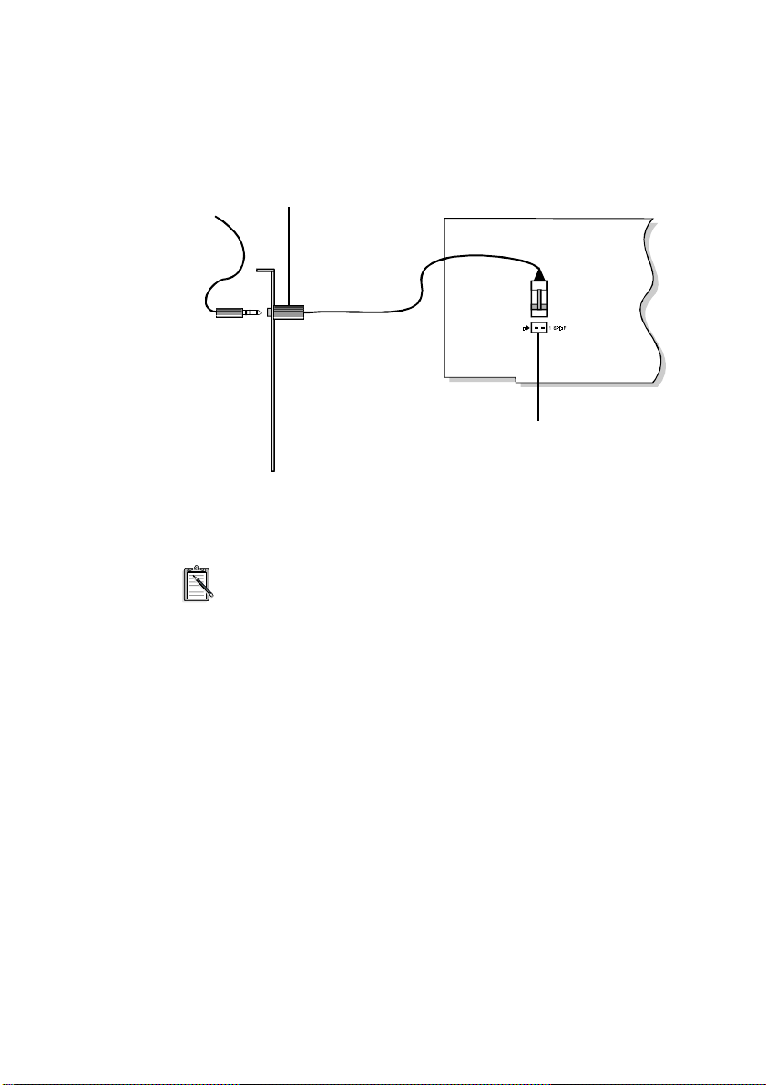
SPDIF Out jack (on separate metal bracket)
Connects an external digital device that uses a
SPDIF connector, such as a Digital Audio Tape
(DAT) machine, for playback or recording.
SPDIF connector (on audio card)
Connects the SPDIF Out jack to trans fer
digital audio signals from your audio card to
a device that also uses a SPDIF connector,
such as the DAT machine.
Figure 1-2: Connection of SPDIF Out jack to SPDIF connector.
The end of the cable attached to the SPDIF Out jack must be
connected to the SPDIF connector on your audio card.
The digital audio signals from the SPDIF Out jack contain audio
output from the EMU8000 wavetable chip mixed with digital voice
playback if the playback is in 16-bit stereo mode, 44.1 kHz CD
quality. If you want to listen to WaveSynth/WG through the SPDIF
Out jack, you must enable the “Enable WaveSynth to play at CD
quali t y ” feat ur e. To do s o :
1. Start CreativeWaveSynth-Waveguide.
The WaveSynth/WG properties sheet appears, displaying the
Profile tab.
2. Click the Performance Settings button.
3. In the Settings dialog box, select the Enable WaveSynth To
Play At CD Quality chec k box and click the OK button.
4. In the WaveSynth/WG properties sheet, click the Quit button
to clos e it .
Setting Up Your Audio Card 1-3
Page 13

Instal ling the Card an d Related Hardware
If you want to install this Plug and Play ( PnP) card in a non-PnP
environment such as DOS/Windows 3.1x or Windows 95
MS-DOS Mode, you must first install a PnP configuration
manager. For more details, refer to the documentation that
comes with your PnP configuration manager.
To install the card and related peripherals:
1. Switch off your sys tem and all peripheral devices, a nd unplug
the power cord from the wall outlet.
2. Touch a metal pla te on your system to ground yourself and
dischar g e an y static elec tr i ci ty .
3. Remove your system’s cover.
4. If you have a memory daughterboard, you may want to mount
it onto your audio card now, as shown in F igure 1-3.
Connector Pins
Figure 1-3: Mounting the DRAM Upgrade daughterboard.
5. Find a free 16-bit expansion slot in your system. Remove the
metal plate from the slot you have chosen and put the screw
aside. The screw will be used in a later step.
1-4 Setting Up Your Audio Card
Housing
Audio Card
DRAM Upgrade
Daughterboard
Page 14
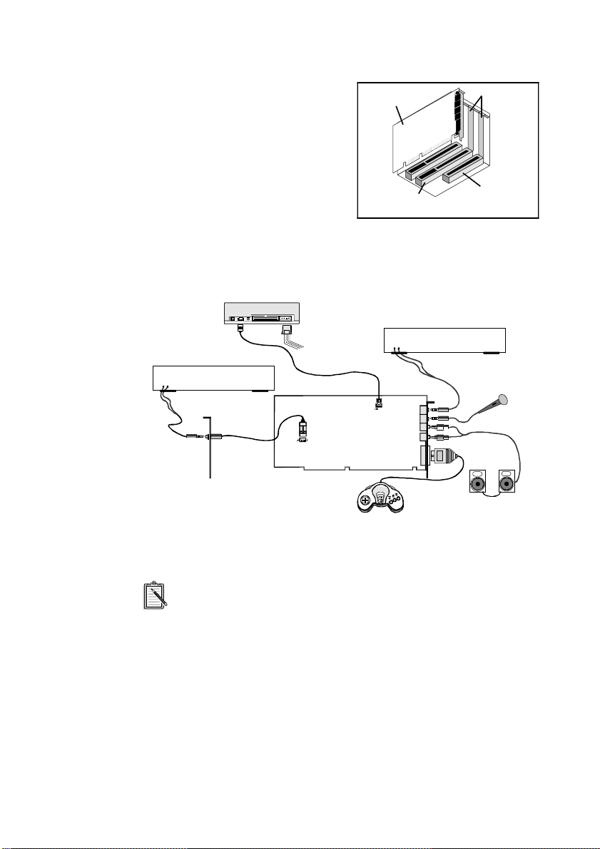
6. Align your card’s 16-bit slot
Figure 1-4
Audio card
Metal plates
16-bit slot
8-bit slot
connector with th e expansion
slot and gentl y lower the card
into the free slot as shown.
7. Sec u r e th e ca r d to th e
expansion slot with the screw
that you removed from the
meta l pl ate.
8. Connect powered speakers or an external amplif ier to the Line
Out jacks. Figure 1-5 sho ws you how to connect various
devices.
CD-ROM drive
Cassette and CD player,
Line-out
synthesizer, etc.
CD Audio
cable
Line In
Mic In
white
red
Microphone
Right
Left
Speakers
External Digital
Line-In
L
Separate metal bracket
Device
R
SPDIF Out
To PC power
supply
SPDIF
connector
Audio card
CD Audio
connector
Line Out Right
Joystick/MIDI
Line Out Left
Gamepad
Figure 1-5: Connecting external speakers and other devices.
The joystick co nnector on your audio ca rd is identical to tha t on
a standard PC game control ada pter or game I/O connector.
You can connect any analog joystick with a 15-pin D-shell
connector. It also works well with any application that is
compatible with the standard PC joystick. To use two
joysticks, you need a Y -cable splitter.
9. Replace your system’s cover.
10. Plug the power cord back into the wall outlet. Switch on the
system.
Setting Up Your Audio Card 1-5
Page 15

To test your DRAM upgrade:
1. Make sure you have installed the audio card’s software. (The
installation of the software will be covered in the next two
chapters.)
2. Start the AWE Control Panel and download SoundFont banks.
From the memory status bar, you should be able to see the
changes in the available memory onboard.
3. Play your SoundFont banks to make sure your DRAM Upgrade
daughterboard is working properly.
Refer to the o nline
User’s Guide
use the AWE Control Panel.
for detailed information on how to
1-6 Setting Up Your Audio Card
Page 16

2
Installing Software in Windows 95
This chapte r shows you how to i nsta ll t he audi o softwa re in Windows
95 after installing your card. It comprises the following sections:
Setting Up the Audio Card Drive r s
❑
Instal ling the Application s
❑
Testing th e I n stallation
❑
Uninstalling the Applications
❑
Sett ing Up th e Audio C ard Dri vers
Proceed to “Ins talling the Applications” on page 2-3 if your
audio card’s drivers are already set up. Otherwise, have your
Windows 95 CD-ROM or installation diskettes available as
they may be needed during the installation.
You need device drive rs to control the component s on your audio card.
After you have installed the card and switched on your system,
Windows 95 aut omat icall y de tect s th e com ponents , an d e ither ins tall s
the drivers or prompts you for the drivers. You may encounter the
following messages, which may not be in the sequence shown.
If a message similar to Figure 2-1 appears, just take note of it
❑
and wait for the next message to ap pear.
Figure 2-1: Message box indicating the det ection of a device.
Install ing Software in Wind ows 95 2-1
Page 17
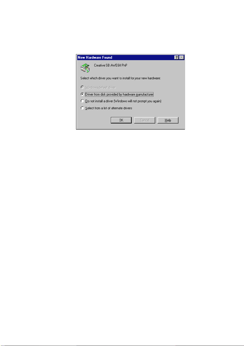
❑ If a dialog box similar to Figure 2-2 appears, click the se cond
option, and then click the OK button.
Figure 2-2: Driver installati on d ialog b ox i n which th e Wind ows def aul t dr iver op tio n
is NOT available.
2-2 Installing Software in Window s 95
Page 18

If the Install From Dis k dialog box appears
❑
1. Insert the ins tallation CD-ROM into your CD-ROM
drive and select the drive.
2. Click the Br owse button and look for a .INF file in the
root directory.
If you cannot find it, se lec t the folder
Language
lang ua g e of th e softw a r e th at you w an t to in s t all.
3. Click the OK button.
The required files are copied to your hard disk.
\WIN95\DRIVERS
Installin g the Applicat ions
To install y our a udio ca rd’s a pplica tions from t he CD-ROM s upplie d
with your package :
1. Ensure you r CD-ROM drive is install ed and worki ng properly.
Refer to the d ocumentation that comes with it for more details.
2. Insert the installation CD-ROM into your CD-ROM drive.
The CD-ROM suppor ts Win dows 95 Auto Play mode and start s
running automatically. If it does not, see Appendix D,
“Troubleshooting”.
3. Follow ins tructions on the screen to complete the ins tallation.
, where
Language
is the
Testing the Installation
After the appli cations are installed, you can use Windows 95 Media
Player to tes t if your audio card is working properly. If you do not
have Media Player, follow the instructions below to install it.
To instal l th e M ed ia Player :
1. Click th e Star t butto n, po int to Set tings , and t hen cli ck Co ntrol
Panel.
2. In the Control Panel window, double-click the Add/Remove
Programs icon.
Install ing Software in Wind ows 95 2-3
Page 19
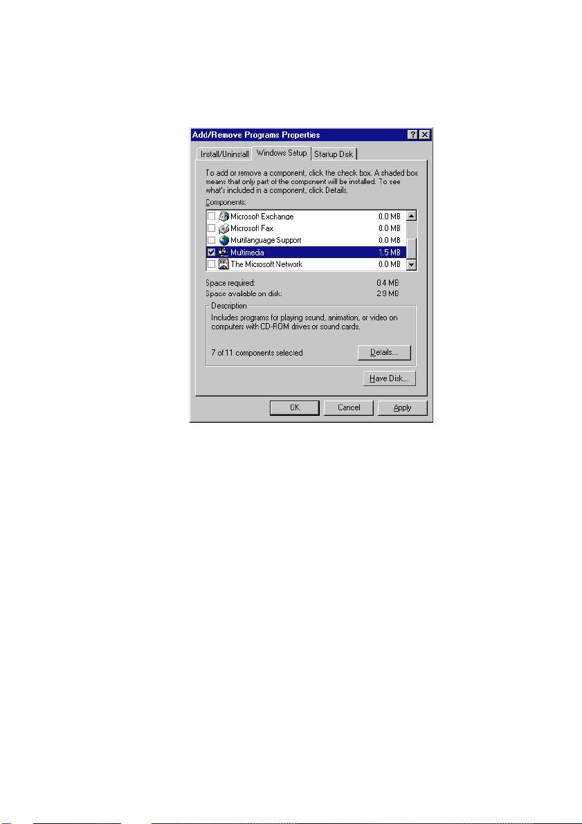
3. Click the Windows Setup tab.
The Windows Setup ta bbed page simil ar to Figure 2-3 appears.
Figure 2-3: The Wi ndows Setup tabbed page.
4. Select the Multimed ia check box and click the Details but ton.
5. In the Multimedia dialog box, select the Media Player
checkbox, then Volume Control, Audio Compression and
Sound Recorder, and click the OK button.
6. Follow the instru ctions on the screen to compl ete the
installation.
To test the audi o card:
2-4 Installing Software in Window s 95
Page 20
1. Click the Start button, point to Programs, point to Acces sories,
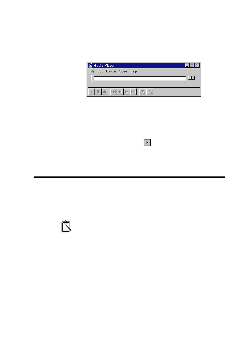
point to Multimedia, and then click Media Player.
The Media Player appe ars as shown in Figure 2-4.
Figure 2-4: The Media Player interface.
2. On the Device menu, click Sound.
3. In the Open dialog box, select a sound from the list, and then
click the Open but ton.
4. On the Media Player, click .
You should hear the se lected sound being played. If you
encounter any problems, see Appendix D, “Troubleshooting”.
Uninstall ing the Appli cations
The Windows 95 Uninstall feature allows you to remove applications
cleanly and then reinstall them to correct problems, change
configurations, or make version upgrades.
Quit the card’s appl ications before uninstalling. Applications
that are still running during uninstallation will not be
uninstalled.
Install ing Software in Wind ows 95 2-5
Page 21

To uninstall the applications:
1. Click the Start butt on, point to Setting s, and then cl ick Contr ol
Panel.
2. Double-click the Add/Remove Programs icon.
The properties sheet similar to Figure 2-5 appears.
Figure 2-5: The Add/Remove Programs Proper ties sheet.
3. Select Sound Bla ster AWE64 Gold a nd cli ck the Add/ Remove
button.
4. Follow the instructions on the scr een to uninstall.
2-6 Installing Software in Window s 95
Page 22

Installing Software in DOS/
Windows 3.1x
This chapter shows you how to install the audio software in
DOS/Windows 3.1x after installing your card. It comprises the
following sections:
Installing the Software
❑
Testing th e I n stallation
❑
Optimizing Memory Usage
❑
Instal ling the Softwar e
To install the software:
1. Insert the installation CD-ROM into your CD-ROM drive.
2. If you are in Windows, exit to DOS.
The installa tion will not work if you install from the DOS
prompt in Windows.
3. At the DOS prompt, chang e to the drive containing your
CD-ROM. For example, type
to driv e D .
4. Type
5. Follow the instructions on the scree n to complete the
INSTALL
installation.
and press <Enter>.
and press <Enter> to change
D:
3
After you have completed the installation and rebooted your system,
proceed to the ne xt section to test if your installation works.
Install ing Software in DOS/ Windows 3.1x 3-1
Page 23

In order to use your AWE64 Plug and Play using
DOS/Windows 3.x, you must ins tall the Creative
Configuration Manager first. This is located on the Creative
CD in the directory
<drive>\<lang>\ctcm\install,
Testing the Installation
Once you have installed the software, you can run the DIAGNOSE
test progr am to t est if t he inst allat ion works . Th is prog ram ch ecks the
base I/O addresses, IRQ line, and DMA channels used by the audio
interface of your audio card. It then display s a menu to let you test the
card’s sound and music output.
To run the test program:
1. At the DOS prompt, chan ge to the directory containing your
audio card’s software. For example, if your directory path is
C:\SB16, type
2. Type
3. Follow the instructions on the screen to complete the test.
If the test program stops or displays an error mes sage, it may be due to
a conflict between the audio interface and another peripheral device.
To resolve the conflict, you have to change the settings of your audio
interface. For more information, see Appendix B, “Understandi ng the
Installation” or Appendix D, “Troubleshooting”.
DIAGNOSE
C:\SB16
and press <Enter>.
e.g. d:\français\ctcm\install
and press <Enter>.
3-2 Installing Software in DOS/ Windows 3.1x
Page 24

Optimizing Memory Usage
If you choos e to install the l ow-level DOS device dr ivers under custom
installat ion (see “Th e CONFIG.SYS File Settings” on p age B-7) , your
system will load them into memory during sy stem startup.
However, if you do not need these drivers (for example, you are
running only Windows applications or playing DOS games), you ca n
bypass load ing these drivers. Otherwise, we recommend t hat you l oad
them into high memory (for example, using memory managers).
Using Memory Managers
You can use one of the following memory managers:
❑ If you are using Microsoft DOS 6.x, run MEMMAKER.
(For details, refe r to your DOS 6.x documentation.)
❑ If you have a memory manager such as QEMM or 386MAX,
refer to their respective documentation for instructions.
Bypassing the Loading of the Low-Level Drivers
You can bypass loading the low-level device drivers by using one of
the these methods:
❑ DOS 6.x’s multiple boot sessions
With this feature, several sessions can be made available for
selection during bootup. One session can contain settings that
load the drivers int o memory. If you do not wa nt to lo ad these
drivers, you c an s elect another session that allows you to boot
up the systemwithout them.
(Refer to y our DOS 6.x do cumen tatio n fo r ins tructi ons on how
to create the multiple boot sessions.)
❑ Bypass the loading of the low-level device drivers
1. During syste m startup, press and ho ld down the <ALT> key
when the message “Start ing MS -DOS .. .” appears.
2. Release the key only when you see the DOS prompt.
Install ing Software in DOS/ Windows 3.1x 3-3
Page 25

Page 26

General Specifications
This appendix lists the general specifications of your audio card.
Plug and Play
ISA Specification version 1.0a compliant
❑
Advanced WavEffects Synthesizer
32-voice polyphony
❑
16 parts multi-timbral
❑
1 MB ROM of General MIDI samples
❑
4 MB built-in DRAM
❑
Stereo Music Synthesizer
4-operator 11-voice or 2-operator 20-voice stereo music
❑
synthesizer
Compatible with previous Sound Blaster and Adlib music
❑
synthesizer chi ps
Stereo Digitized Voice Channel
Full duplex
❑
16-bit and 8-bit digitizing in stereo and mono mode s
❑
Programmable sam pling rates, 5 kHz to 44.1 kHz in linear
❑
steps. Your audio applications may support only se lected
ranges of sampling rates.
High and Low DMA channels u sing a si ngle i nterrupt fo r audio
❑
playback and recording
Dynamic filtering for digital audio recording and playback
❑
A
General Sp ecifications A-1
Page 27

Built-in Digital/Analog Mixer
Mixes sources from digitized voice and inputs from MIDI
❑
devices, CD Audio, Line In, Microphone, and PC Speaker
Selectable input source or mixing of various audio sources for
❑
recording
Volume Control
Software volume control of Master Volume, Digitized Voice ,
❑
and inputs from MIDI device , CD Audio, Line In, Microphone,
and PC Speaker
PC Speaker at 4 levels in 6 dB steps
❑
All sources at 32 levels in 2 dB steps
❑
Treble/Bass control at 15 levels fro m -14 dB t o 14 dB in 2 dB
❑
steps
Full software control of fade-in , fad e-out, and panning
❑
3D Stereo Enhancement Technology
Increased depth and breadth in perceived audio
❑
Enhances mono and stereo audio output
❑
Independent of speaker quality
❑
Independent of setup configuration (for example, placement
❑
and alignment of sp ea kers with the listener)
MIDI Interface
Built-in MIDI interface for connection to external MIDI
❑
devices
Upgrade Options
DRAM upgrade interface for more sound samples
❑
A-2 General Specifications
Page 28

B
Understanding the Installation
This appendix is organized as follows:
Understanding the Software-Configurable Settings
❑
Understanding the Environment Variables
❑
Understanding the Installation Program in Windows 3. 1x
❑
Unders tanding the So ftware-Co nfigurable
Sett ings
Your audio ca rd supp orts t he P lug and Play (P nP) 1.0a sta ndard. This
allows a PnP system to assign the necessary resourc es such as I/O
addresses, interrupt lines and DMA channels to your card when you
instal l it .
If you are using Windows 95, its PnP configuration manager will
automatica lly set up your c ard’s resou rces. If y ou are usin g a non-PnP
system such as Windows 3.1x, you must run your PnP configuration
manager to c onfigure the card. For deta il s, refer t o the docum entation
of your PnP configuration manager.
This section explains the following software-configurable resources
of your audio card:
Input/Outp ut (I/O) Addresses
❑
Interrupt Reque s t (IRQ) Li nes
❑
Direct Memory Access (DMA) Channels
❑
Understanding the Installation B-1
Page 29

If your card encounters a confli ct with a periphera l device, you
may need to change its resource settings. If you are using
Windows 95, run the Device Manag er. If you are using
Windows 3.1x, run the configuration utility that comes with
your PnP configurati on manager. For detail s, see Appendix D,
“Resolving Conf lic ts” . When any res ource se tti ng is c hanged,
ensure the environment variables (see “Understanding the
Environment Variables” on page B-3) reflect the changes as
well. You can view your syste m en vironment by typing
at the DOS prompt.
Input/Output (I/O) Addresses
I/O addresses are communication areas used by your computer’s
central proces sor to distinguish among various pe ripheral devices
connected to your sy stem when sending or receiving data.
Table B-1 lists the default I/O address ranges assigned by the PnP
system to various devices on your audio card.
Table B-1: Possible default I/O addresses occupied by the audio card.
I/O Address Range Device
200H to 207H Game/Joystick port
SET
220H to 22FH Audio interface
330H to 331H MPU-401 UART MIDI
388H to 38BH Stereo music synthesizer
620H to 623H,
A20H to A23H,
E20H to E23H
100H 3D Stereo Enhancement device
B-2 U nd er stand in g the Inst al latio n
Advanced WavEffects synthesizer
Page 30

Interrupt Request (IRQ) Lines
An IRQ line is a signal line a device uses to notify your computer’s
central process or that it wants to send or receive data for processing.
Table B-2 lists an example of an IRQ line that may be assigned to the
audio interface on your audio card.
Table B-2: Possible default IRQ line assignments.
IRQ Line Device
5 Audio interface
Direct Memory Access (DMA) Channels
A DMA channel is a data channel a device uses to transfer data
directly to and from the system memory. Your card’s audio interface
transfers data through the Low and High DMA channels.
Table B-3 shows a possible combination of DMA channels that may
be assig ned to the audio in terface.
Table B-3: Possible default DMA channel assignments.
DMA Channel Usage
1 Au dio Low DMA channel
5 Au dio High DMA channel
Understanding the Environment Variables
Environment variables are used to pass information about how your
card is configured to programs in your system. This section explains
the environment variables of your audio card:
❑ SOUND Environment Variable
❑ BLASTER Environment Vari able
❑ MIDI Environment Variable
Understanding the Installation B-3
Page 31

SOUND Enviro nm ent Vari a ble
The SOUND environment variable specifies the directory location of
your audio card’s drivers and applications. The syntax for this
variab le is as follows :
SOUND=
where
(e.g., C:\ SB16 ). No space is allowed be fore and after the equal sign.
path
is the drive and dir ectory of the card’s software
path
BLASTER Environment Variable
The BLAS T E R en vi r o nm en t var i ab l e s p ec if i es th e base I/O ad d re ss,
IRQ line, and DMA channels of the audio interface. Its syntax is:
BLASTER=A220 I5 D1 H5 P330 E620 T6
The values shown earl ier may be diffe rent for your s ystem. No
space is allowed before and after the equal sign. However,
ther e must be at least on e space between parameters.
The param e t er s in th e command ar e d escribe d as follows.
Paramet e r Descr ipt i o n
A
xxx
I
x
D
x
H
x
P
xxx
E
xxx
T
x
Speci f ies the audio interface’s base I/O address.
defaults to 220.
xxx
Specif ies the IRQ line used b y the audio interface.
defaults to 5.
x
Specifies t he Lo w DMA channel used by the audio
interface. x defau lts to 1 .
Specifies the High DMA channel used by the audio
interface. x defau lts to 5 .
Specifies t he MPU-401 UART interface’s base I/O
address.
Specifies t he Adva nced WavEffects synthesizer
chip’s base I/O addr es s.
Specifies the card type. x must be 6.
defaults to 330.
xxx
can be 620.
xxx
B-4 U nd er stand in g the Inst al latio n
Page 32

MIDI Environment Variable
The MIDI environment variable specifies the MIDI file format used
and where MIDI data is sent to. MIDI data can be sent to the internal
stereo music synthe sizer or MIDI port.
Generally, there a re three MIDI file formats: Genera l MIDI, Extended
MIDI and Basic MIDI. The synta x for this variable is as follows:
MIDI=SYNTH:x MAP:x MODE:
The parameters in the command are described below.
Parameter Description
SYNTH:
MAP:
x x
MODE:
x x
x x
can be 1 or 2.
1 (default setting) specifies the stereo music
synthesizer.
2 specifies the MIDI port.
can be G, E, or B.
G specifies the General MIDI file format.
E (default setting) s pecifies the Extended MIDI file
format.
B specifies the Basic MIDI f ile form at .
can be 0, 1, or 2.
0 (factory default) s pec ifies General MIDI mode.
1 specifies General Standard mode.
2 specifies MT-32 mode.
x
Understanding the In stallation Program in
Windows 3.1x
When you install the audio software, the installa tion program creates
a director y and c opies the s oftware in to it. It then a llows you to set up
your Windows applic ations by adding a command to the WIN.INI file
to run WINSETUP.EXE. This command automatically creates the
audio card program gr oup and the applic ation ic ons when y ou next run
Windows.
Understanding the Installation B-5
Page 33

You can also choose to set up your Windows applications at a
later time by running INS TALL in th e audio soft ware directory
on your hard disk. INSTALL also allows you to sel ectivel y set
up components tha t were not installed previously.
The installa tion program also modifies your AUTOEXEC.BAT and
CONFIG.SYS files.
The AUTOEXEC.BAT File Settings
The insta llation program adds the fo llowing statements to the
AUTOEXEC.BAT file:
SET BLASTER=A220 I5 D1 H5 P330 E620 T6
SET SOUND =C :\ SB 16
SET MIDI=SYNTH:1 MAP:E MODE:0
C:\SB16\DIAGNOSE /S /W=C:\WINDOWS
C:\SB16\MIXERSET /P /Q
C:\SB16\AWEUTIL /S
The first 3 stateme nts se t up the en vironme nt varia bles for your audio
card.The last 3 stat ements run the DIAGNOSE, MIXERSET, and
AWEUTIL utilities. The BLASTER statement is added by the
DIAGNOSE utility, and the values shown above may differ from
those in your system.
❑ Running DIAGNOSE with the /S parameter updates the
BLASTER environment with the resource settings from the
PnP configur ation manager.
❑ Running DIAGNOSE with the /W=C:\WINDOWS parameter
updates the SYSTEM.INI file in the Windows directory with
the resource settings from the PnP configuration mana ger.
For a description of the AWEUTIL utility, refer to the
AWEUTIL.TXT file found in the installa tion direct ory of your
audio card.
B-6 U nd er stand in g the Inst al latio n
Page 34

The CONFIG.SYS File Settings
If you choos e to install the l ow-level DOS device dr ivers under custom
installation, the installation progra m also adds the following
statements to the CON FIG.SYS file:
DEVICE= C:\S B16\DRV\CTSB16.SYS /UNI T=0
/BLASTER=A:220 I:5 D:1 H:5
DEVICE= C:\SB16\DRV\CTMMSYS.SYS
CTSB16.SYS and CTMMSYS.SYS are low-level device drivers that
provide wave pla ybac k and recording for DOS applications. These
applicat ions include third-party DOS applic ations developed with
Creative Labs’ Sound Blaster Developer Kit. The applications work
with the drivers (such as CTWDSK.D RV, CTWMEM.DRV,
CTVDSK.DRV, and CT-VOICE.DRV) that require the low-level
drivers. The dri vers are foun d in the DRV su bdirect ory of your aud io
software direct ory.
See “Optimizing Memory Usage” on page 3-3 to learn how to
optimize your memory.
If your system does not have enough memory when you are using
Windows applications or playing DOS games, you can delete the
above two statements from the CONFIG.SYS file using a text edit or.
At a later time, you may discover that you need the low-level device
drivers fo r your soft ware applic ation. You can l oad them i nto memory
by typing
DIAGNOSE /A
This command adds the required s tatements to the CONFIG.SYS file.
at the DOS prompt and pressing <Enter>.
Understanding the Installation B-7
Page 35

Page 36

C
Changing Audio Card Settings
This chapter is organized as follows:
Enabling/Disabling Creative 3D Stereo Enhancement Effect
❑
Enabling/Disabling Full Duplex Operation
❑
Enabling/Disabling MPU-401 MIDI Emulation
❑
Enabling/Disabling Joystick Interfac e
❑
Enabling/Disabling Creative 3D Stereo
Enhancement Effect
The Creative 3D Stereo Enhancement effect allows you to eliminate
speake r cr osstalk w h ic h o cc ur s wh en tw o spe ak ers are pl ac ed cl o se
together. With this effect enabled, mono and stereo sounds produced
by your speakers wil l have increased depth and breadth.
This effect can be enabled or disabled in Windows 95 and MS-DOS.
If your pair of s peaker s or anoth er device already has a built -in
3D sound technology, do not activate this feature in both
devices. The 3D Stereo Enhancement effect, when activated
with another 3D sound technology, may distort the audio
output.
In Windows 95
To enable or disable the effect in Windows 95:
1. Click th e Star t butto n, po int to Set tings , and t hen cli ck Co ntrol
Panel.
2. In the Control Panel window, double-click the System icon.
3. In the System Properties sheet, click the Device Manager tab.
Changing Audio Card Settings C-1
Page 37

4. In the Device Manager tab, double-click Sound, Video And
Game Controllers.
5. Select Creative AWE64 16-bit Audio (SB16-compatible) and
click the Properties button.
6. In the properties sheet, click the Settings tab.
7. To enable the Creative 3D Stereo Enhancement effect, select
the Enable Creat ive 3D Stereo Enhancement check box in the
Settings tabbed page.
To disable the effect, click to clear the check box.
8. Click the OK button.
In MS-DOS/Windows 3.1x
To enable or disable t h e effect in MS-DOS:
1. At the MS-DOS prompt, change to the direct ory containing
your audio card’s software; for example C:\SB16.
2. To enable the effect, type
To disable the ef fect, type
CT3DSE ON
CT3DSE OFF
.
.
Enabling/Disabling Full Duplex Operation
Full duplex is a feature in your audio card that allows you to record and
play back audio data simultaneously. It is useful for audio
conferenci ng and tel ephone-li ke applicat ions. Whe n it is ena bled, you
can play back and recor d at the same time. However, there are some
limitations:
❑ You can start only one session of simultaneous playback and
recording.
❑ You must use the same sampling rate for both playback and
recording.
For example, since Creative WaveSynth/WG does a Wave
playback at 22 kHz, you can rec ord at only 22 kHz.
❑ You cannot play other Wave files when using Creative
WaveSynth/WG.
❑ You cannot add reverb effe ct when you play back Wave files.
C-2 Changing Audio Card Settings
Page 38

When full duplex is disabled, you can play a Wave file (or other
sounds) together with Creative WaveSynth/WG, or add reverb to the
playback but you cannot record at the same time. The full duplex
feature can be enabled or disa bled in Windows 95 and Win dows 3.1x.
In Windows 95
To enable or disable full duplex in Windows 95:
1. Repeat steps 1 - 7 of “In Windows 95” on page C-1 under
“Enabling/Dis abli ng Creati ve 3D Ste re o Enha ncement Effect”.
2. To enable full duplex, select the Allow Full Duplex Operation
check box in the Settings tabbed page.
To disable the feature, click to clear the check box.
3. Click the OK button.
In Windows 3.1x
To enable or disable full duplex in Windows 3.1x:
1. Launch your File Manager.
2. Locate the SYSTEM.INI file in your Windows directory.
3. Do ub l e- click th e f il e.
A text edito r appears, displaying the contents of the file.
4. Under the section
FullDuplex=1
To enabl e th e feature, m ak e su r e
To disable it, mak e sure
5. Save the file.
6. Restart your system for the driv ers to be updated.
[sndblst.drv]
or
FullDuplex=0
, look for the line
.
FullDuple x=1
FullDuplex=0
.
.
Enabling/Disabling MPU-401 MIDI Emulation
The MPU-401 MIDI Emulation f eature allows most real mode game s,
which do not support wavetable synthesis, to play wavetable music
from th e au dio card. The MI D I output from the games is direct ed to
the wavetable synthesizer rather than the MPU-401 interface. Games
that have not b ee n designe d to use the wa vetabl e s ynthes is f eature s on
your card can now use them.
Changing Audio Card Settings C-3
Page 39

You must install the DOS AWEUTIL utility for the MIDI
Emulation fe ature to funct ion properly . For more infor mation,
refer to the AWEUTIL.TXT file in your audio card’s
installation directory.
Protected mode software does not support MIDI Emulation.
You can still play music from such software by using the
4-operator synthesizer chip.
The MIDI Emula tion feature can be ena bled or disabled in Windows
95 and MS-DOS/Windows 3.1x.
In Windows 95
To enable or disable the fe ature in Windows 95:
1. Start the AWE Control Panel.
2. In the AWE Control Panel, click the Device button.
3. In the Devi ce Selection dialog box, selec t the Allow MPU401
Emulation On T his Devic e check box , and then cli ck the S elect
button.
4. In the AWE Control Panel, click the Quit button to close the
AWE Control Pane.
In MS-DOS/Windows 3.1x
To enable or disable t h e feature in MS-DO S:
1. If your audio c ard is already in stalled, switch off your computer
and all other peripheral devices. Then remove your system’s
cover and the audio card.
C-4 Changing Audio Card Settings
Page 40

2. Enable or di sabl e the MF BEN jumper a ccor di ng to the sett ings
shown in Figure C-1.
Enabled (Factory
default setting)
Figure C-1: The available MPU-40 1 MIDI Emulation sett ings.
Enabling/Disabling Joystick Interface
The Gamepad Joystick interface can be enabled or disabled in
Windows 95 and MS-DOS/Windows 3.1x.
In Windows 95
To enable or disable the interface in Windows 95:
1. Click th e Star t butto n, po int to Set tings , and t hen cli ck Co ntrol
Panel.
2. In the Control Panel window, double-click the System icon.
3. In the System Properties sheet, click the Device Manager tab.
4. To enable or disable the Jo ystick interface, double-clic k Sound,
Video And Game Controllers and select Gameport Joystick in
the Device Manager tabbe d page.
5. Click the Properties button.
Disabled
Changing Audio Card Settings C-5
Page 41

6. To disable the inter f ace, clear the Original Configuration
(Current) check box in the General tabbed page of the
properties sheet.
To enable it, select the check box.
7. Click the OK button and restart Windows 95 for the change to
take effect.
After restarting Windows 95 to effect the interface disabling,
please disregard the information displayed in the Resource
Settings box on the Resources tab of the Properties sheet.
The
is the cleared Original Configuration (Current) check box .
When you re-enable the interface for use by another device,
Windows 95 might warn you that there is a conflicting device
or tha t the re source area asso ciat ed with t he i nterf ace is alrea dy
in use. Ignore this warning. The new device should function
perfectly despite the warning.
indicator tha t your int erf ace h as i ndeed been d isabl ed
only
In MS-DOS/Windows 3.1x
To enable or disable t h e in terface in MS-DOS:
1. Exit to MS-DOS if you are in Windows 3.1x.
2. Change to the directory where your CTCM and CTCU
programs are installed. The default directory is C:\ CTCM.
Type
CTCU
3. On the Menu menu of the Creative Plug and Play
Configuration Utility screen, click PnP Cards.
4. In the List of PnP Cards li st, c lick you r Creati ve Plu g and Play
card. In the List of Devices list, click Gameport.
5. Click the Res ources button.
The current resources assigned to the interface are displayed.
6. To disable the interface, select the Disable check box in the
Resources window.
To enable it, click to clear the check box.
7. Click the OK button twice.
8. On the Menu menu, click Exit. Type the path of your Windows
3.1x directory (for example, C:\Windows) and press <Enter>.
9. Restart your system for the change to take effect.
and press <Enter>.
C-6 Changing Audio Card Settings
Page 42

D
Troubl eshoot i ng
This appendix pro vides some tips for solving som e problems you may
encounter with your audio card during installation or norm al use.
Problems Installin g Audio Card Software
from CD-R OM
Problem
Cause
Solution
In Windows 95, the insta llation program does not run
automatically when you insert the CD-ROM into the
drive.
The AutoPlay notification setting in your Windows 95
system may not be enabled.
Try one of the followin g:
Select the Auto Insert Notification check box.
❑
To do this:
1. Click the Start bu tton, p oint to Se ttings, and the n
click Contr ol P anel.
2. In the Control Panel window, double-click the
System icon.
3. In t h e System Properties sheet, click the Dev ice
Manager tab and selec t your CD-ROM drive.
4. Click the Properties button.
5. In the pro pertie s s heet, cli ck the Set tings tab and
select the Auto Insert Notification check box.
Troubleshooting D-1
Page 43

Alternatively, if you do not want to select the Auto
❑
Insert Notifica tion check box, pe rform the following
1. Double-cl ick the My Computer icon on your
Windows 95 desktop.
2. In the My Computer window, right-click the
CD-ROM drive icon.
3. On the shortcut menu, click AutoPl ay and follow
the instructions that appear.
Problems with Sound
Problem
Causes
Solution
No output from both the 8-bi t and 16-bit digitized
sounds when running the test program.
1. The volum e knob o n t he s peake rs is n ot set pr operly.
2. The external a mpl ifier or speakers are connected t o
the wrong jack.
3. The spea ker amplifiers are in the On position.
If you are using powere d speakers in a non-p owered
state, turn off their amplifiers.
4. There is hardware conflict.
Verify the following:
❑ Volume contro l knob of the spe akers, if any, is s et at
mid-range.
❑ External ampli fier or powered speakers are
connected to the card’s Line Out jacks.
❑ No hardware conflict between the ca r d and another
peripheral de vice. For details, see “Resolving
Conflicts” on page D-5.
❑ Amplifiers on speakers are in the Off position.
D-2 Troubleshooting
Page 44

Problems in MS-DOS
Problem
Cause
Solution
Problem
Cause
Solution
SOUND or BLASTER environm ent could not be found.
The command to set up the SOUND or BLASTER
environment might not be included in the
AUTOEXEC.BAT file.
When you install your audio card’s software, the
comman d s ar e aut o m a ti cally add e d to th e
AUTOEXEC.BAT file so that both envi ronment st rings
are set up when your system restarts.
To add the command to set up the BLASTER
environment in the respective system files, run
DIAGNOSE (See “Understanding the Inst allation” on
page B-1.).
To set up th e SOUND envi ronment, ins ert the statement
SET SOUND=C:\SB16
file using a text edi tor. Reboot your system.
Error message “Out of enviro nment space”.
The syst em environment space is used up.
Add the statement
/E:512 /P
size for the syste m environment space. You can choose
a higher v alue if the environ ment size is already
512 bytes. (Normally, the next value is 1024 bytes. )
For details, refe r to your DOS manual.
to the CONFIG.SYS file. /E defines a new
into the AUTOEXEC.BAT
SHELL=C:\COMMAND.COM
Troubleshooting D-3
Page 45

Problem
Cause
System hangs duri ng t he 16 -bit di gitiz ed s ound tes t, but
it works fine during the 8-bit test.
Your system’s motherboa rd ca nnot handle High DMA
at full sp ee d. On so me machin es , th e D M A co ntr o ll er
on the motherboard does not function properly during
High DMA transfers. High DMA transfers on such
machines might corrupt the data in main memory and
cause the system to hang or encounter a parity error.
Solution
Run the Plug and Play configuration utility and select
Low DMA in place of the High DMA channel. 16-bit
audio data will then be transferred through the Low
DMA channel.
When you set your High DMA channel to Low
DMA, you will lose the full-duplex operation,
which requires two separate DMA channels.
Problems in Windows 3.1x
The following are problems you might encounter when in
Windows 3.1x:
Problem
Cause
Solution
No sound is heard when runnin g your audi o card’s
Windows applications.
One or more of the sound dri vers might not be i nclude d
in the SY STEM. INI file.
Check the SYSTEM.INI file. To do so:
1. On the File menu in Program Manager, click Run.
2. Type
SYSEDIT
click the OK button .
in the Command Line box and
D-4 Troubleshooting
Page 46

3. Make su r e the followin g statements ar e p resent:
[boot]
drivers=mmsystem.dll msmixmgr.dll
[386enh]
device=vsbpd. 386
device=vsba we.386
[drivers]
timer=timer.drv
midimapper=midimap.drv
Aux=sb16snd.drv
Mixer=sb16snd.drv
Wave=sb16snd.drv
MIDI=sbawe32.drv
MIDI1=sb16fm.drv
MIDI2=sb16snd.drv
[sndblst.drv]
Port=220
MIDIPort=330
Int=5
DmaChannel=1
HDmaChannel=5
The values shown in the [sndblst.drv] group may be different
in your system.
If one or more of the statements are missing, run INSTALL in DOS.
INSTALL rewrit es SYSTEM .INI to set up th e d r iv ers an d th e
Windows applications.
Resolving Conflicts
Conflicts occur when two or more pe ripheral devices contend for the
same resources. Conflicts between your audio card and another
peripheral device may occur if your card and the other device are set
to use the same I/O address, IRQ line, or DMA channel.
Troubleshooting D-5
Page 47

Resolving Conflicts in Windows 95
To resolve conflicts in Windows 95, run Device Manager to change
the resource settings of your audio card or the conflicti ng peripheral
device in your system.
To change the resource setting:
1. Click the Start bu tto n, point to Set ti ngs, and t hen c lick C ontro l
Panel.
2. In the Control Panel window, double-click the System icon.
3. In the System Properties shee t, click the Device Manager tab.
4. In the Device Manager tab, double-click Sound, Video And
Game Controllers.
5. Select your audio card and click the Properties button.
6. In the properties sheet, click the Reso u r ces tab.
7. Select the Use Automatic Settings check box.
If this check box is already selected, open the properties sheet
of the conflicting device and select the same check b o x t h ere.
8. Reboot your system to allow Windows 95 to reas sign resources
to your audio card and/or the conflicting device.
The Conflicting Device List box shows you which peripheral
device is confli cting with your audio card. This box is
displayed on the Resources tab of your audio card’s properties
sheet.
Resolving Conflicts in MS-DOS/Windows 3.1x
To resolve conflicts in MS-DOS/Windows 3.1x:
1. Run your Plug and Play co nfiguration utility.
2. Reselect the resource settings of your audio card that are in
conflict. For more detai ls , refer to the documentation that
comes with your Plug and Play configuration utility.
D-6 Troubleshooting
Page 48

Techni cal Su pp ort
For the lates t tec hnical support information, please refer to the
‘Creative Technical Services’ leaflet, supplied with your product.
We are committed to giving you the best product as well as the best
technical support. Please enter the following information in the table
below and have it ready when you contact Technical Support.
The model and serial numbers of your card and other devices.
❑
Error message on the screen and how it came about.
❑
Information on the adapter car d that conflicts with your card.
❑
Hardware configur ation information such as the base I/O
❑
address, IRQ line, or DMA channel used.
Please ens ure to ret ain your pur chase rece ipt plus all packa ging
and content s unt il such ti me th at a ll compon ents of the produ ct
are functioning to your satisfaction. They will all be required in
the unlikely e vent that your product needs to be returned to
Creative.
Before contacting ‘Cre ative Technical Servi ces’, please ensure
that you have read Appendix D, ‘Troubleshooting’.
E
Technical Support E-1
Page 49

For quick and easy reference, it is advisable that you write down the
following numbers of your card and other hardware devices, if
installed in your system in Table E-1 and Table E-2.
Table E-1: Model and Serial Numbers of your hardware.
Hardware Model Number Serial Number
Audio Card*
Video Card
Fax/Modem
CD-ROM Drive
MIDI Device
Others:
See labe l on un de rside of car d
*
Table E-2: Hardware Configuration Information.
Hardware Base I/O Address IRQ DMA
Audio Card
Video Card
Fax/Modem
CD-ROM Drive
MIDI Device
Others:
This section sh ows whe re you can contact us.
❑
❑
❑
E-2 Technical Support
Inside Europe
Through CompuServe
By Fax
Page 50

Inside Europe
See ‘Cre ative Technical Ser vices’ leaflet for details.
Thro ugh Com puSer ve
To serve you better, we ha ve created a Creative Labs Forum on
CompuServe. Through thi s forum:
❑ You will have direc t ac cess to our company representatives
who will be there to answer your questions.
❑ You will be part of an inte ractive community of Creative’s
product users. Here you can share experiences and ideas and
also seek solutions to problems.
❑ We will also keep you up-to-date on the latest product
information, softwa re update s, and fixes to common pr oblems.
❑ We will also welc ome you r recomme ndatio ns and sugg esti ons
for new products and for improving our products in future
releases.
See ‘Cre ative Technical Ser vices’ leaflet for details.
By Fax
For fast and efficient Technical Support solutions, please use our
telephone service in the first instance. If you decide to write o r fax us
then please send your correspondence ONLY to our Ireland address.
Please allow up to two weeks processing and postal time for a
response. See ‘Creative Technical Services’ leaflet for details.
FaxBack
information through facsimile services. In Europe, use the following
number:
is a facility that allows you to obtain product and technical
+353 1 8203667
.
Technical Support E-3
Page 51

™
Quic k S t art
This leaflet contains abbreviated information to get you started right away.
This information is organiz ed a s follows :
1. Installatio n instru c tions fo r Windo ws 95.
❑ Setting up Mic roso ft Int erne t Ex plore r
❑ Setting up Dialing and Service Provider Information
❑ Setting up a Dial Up Script
2. Installation instructions for Windows 3x.
❑ Setting up Mic roso ft Int ern et Ex plo rer
❑ Setting up Real Audio
3. A Creative Webphone Guide to help you get on line.
Interneted Audio
Installing Software f or Windows 95
To install the accompanying applications for Windows 95:
1. Ensure that your CD-ROM dri ve is instal led and work ing prope rly.
If not, refer to the document that comes with your drive to solve the
problem.
2. Load the installation CD-ROM into your CD-ROM drive.
The installation CD-ROM supports Windows 95 AutoPlay mode
and starts running automatically.
3. Choo se the desire d appl ic atio ns to insta ll.
4. Follow the instructions on the screen to finish installing your
applications.
1
Page 52

To install Real Audio as a compon en t of Micro s oft Intern et
Explorer 3. 0, Microsoft Internet Explorer 3.0 must be fully
installed. To do this, follow the instructions above with Real
Audio not che cked, and reboo t your computer . Then fol low the
instructio ns above and install Real Audi o only.
Setting Up Microsoft Internet Explorer
If you have installed Microsoft Inter net Explorer, you need to configure
Windows 95 an d set u p Micr osoft Int ernet Explorer for you r Int ernet S ervice
Provider .
Before you proceed to set up Microsoft Internet Explorer, get the foll ow ing
ready:
1. Windows 95 CD-ROM to install the required drivers when
prompted.
2. Information from your Internet Service Provider:
❑ The name of your Internet Service Provi der.
❑ Your user or acco unt name.
❑ Your password.
❑ The phone number to dial up your Interne t S e r vice Provider.
❑ Your DNS server address.
❑ Your IP address and subnet mask. This is usually not required
as the Service Provider may automatically assign one to you
each time you log on.
❑ A dial-up script. This is required by some Internet Service
Providers.
❑ Your proxy s erver and port number. This is required by some
Internet Service Providers.
2
Page 53

❑ If you intend to use Micros oft Exchan ge to handl e your e- mail,
you would need the following additional information:
a. Your e-mail address.
b. Your Internet mail server.
If you do not have the above information, call your
Internet Service Provider to obtain them.
To set up Microsoft Internet Explor er, you need to do the follow ing:
❑ Set up the dialing and Service Provider information.
❑ Set up a dial-up script (if a dial-up script is required by your
Service Provider).
Setting Up the Dialing and Service Provider
Information
To set up the dialing and Service Prov ide r inform atio n :
1. Click Start on the taskbar.
2. Select Programs , fol lowed b y Access or ies, an d then Inter net Tool s
to run “Get On The Internet”.
3. Under “Setup Options” choose “Manual” and click Next.
4. Click Next on the “Welcome to Internet Setup” dialog box to
access the “How to Connect” dialog box.
5. Select “Con nect using my phone line” and cl ick Next.
6. You will be prompted to select whether you would like to use
Microsoft E xchange to handle your In ternet mail. Select you r
choice and click Next.
7. Click Next to in s tall files and driver to access the Internet. If
prompted, insert the Windows 95 CD-ROM to install the required
drivers.
8. Enter the Name of Service Provider and click Next.
9. Enter the phone number to dial up your I nternet Service Prov ider
and cl ic k Next.
3
Page 54

10. Enter your user name and password and click Next.
11. In the IP Address dialog box, select “My Internet Ser vice Provider
automatically assign me one” and click Next.
12. Enter the addresses for DNS Server and Alternate DNS Server. The
addr es s is ma d e of f o ur nu m be r s separat e d by pe r iods, e.g.,
“149.174.211.5”.
13. If you have chosen to let Microsoft Exchange to handle your
Internet mail (see step 7):
a. Enter your e-mail address and Internet mail server and click
Next.
b. Click Next i n the Exchange Profile dialog box.
14. Click Finis h to comp le te the setu p .
15. If your Service Provider requires a proxy server, follo w the steps
below to configure it:
a. Click Start on the taskbar.
b. Select Settings, followed by Control Panel.
c. Doubl e -click th e Internet ic on.
d. Select the Connection tab.
e. Ensure that the User Proxy Server box is checked.
f. Click the Settings button in the Proxy Server box and in the
Server bo x type the Proxy s erver address followed by the port
number. E.g., If your Service Provider’s proxy server is
proxy.myi s p.com and the port number is 8080, then the entry
should be “proxy.myisp.com:8080”.
g. Click OK.
4
Page 55

To Set Up a Dial- Up Script
Ignore this section if your Service Provider does not require a
dial-up script. If using Dial-U p Scripting, do not check the “Bring
Up Terminal Window” option.
To set up a dial-up scri pt:
1. If you have not installed the Dial-Up Scripting Tool, fol low the
steps below to install the tool:
a. I nsert th e Wind ows 95 CD-ROM into your CD-ROM drive.
b. Using the Control Panel, select A dd/Remove Programs.
c. Select Windows Setup from the Title Bar.
d. Select Have Disk, Browse and locate the RNAPLUS.INF file
in \ADMIN\APPTOOLS\DSCRIPT\.
e. Click OK and follow th e instruct ions on scr een to compl ete the
installation.
2. You will nee d a dial-up script (filename.SCP) in the dire ctory
\Program Files\Accessories\ of your system. This is usually
provided by your Internet Serv ice Provider.
If you do not have a di al-up script, che ck with your Interne t Ser vice
Provider whet her you need one and where can you do w nload one
to your system.
3. Once the Dial-Up Scripting Tool is inst alled:
a. Click Start on the taskbar.
b. Select Programs , followed by Accessories to run the Dial-Up
Scripting Tool.
c. In the Connections section, select the name of your Internet
Service Provider.
d. Click Browse and double-click on t he s cript file name you
created in step 2.
e. Click Apply and click Clo s e.
5
Page 56

4. Finally, make sure that TCP/IP is the only option selected as the
allowed networ k protocol:
a. Right-clic k The Inte rnet ic on on your desk top
b. Select Propert ies
c. Select Propert ies a second time from th e Dialing box unde r the
Connection tab.
c. Select Server Type
d. Ensure that TCP/ IP is the only option selected as the allowed
network pro tocol.
Running Microsoft Internet Explorer
Once you have set up M icrosoft Internet Explorer, you are ready to connect
to your Internet S ervice Provider. To do so, double-click The Internet ico n
on your desk top.
Installing Software f or Windows 3.x
To install the accompanying software for Windows 3.x:
1. Ensure that your CD-ROM dri ve is instal led and work ing prope rly.
If not, refer to the document that comes with your drive to solve the
problem.
2. Start Windows.
3. Load the installation CD-ROM into your CD-ROM drive.
4. Select Run fr om the File menu.
6
Page 57

5. Type the drive letter of your CD-ROM drive, followed by the
directory and i nst alla tion co mmand for the desi red appl icati on ( see
table below).
For example , to insta ll We bPh on e, typ e
D:\WEBPHON E\W PSETUP. EXE
Application Directory Command
Microsoft
Internet
Explorer
Real Audio \RA RA16_30
WebPhone \WEBPHONE WPSETUP
\MSIE\WIN31 SETUP
.
6. Follow the instructions on the screen to finish installing your
application.
7. Repeat steps 4 to 6 until you have insta ll e d all the desired
application s .
Setting up Microsoft Internet Explorer
When you ha ve ins talle d M icro soft Int ern et E xplor er, y ou ne ed t o co nf igure
your modem to be recognized under Windo w s 3.x and set up Microsoft
Internet Explorer for your Internet Service Provider.
Before you se t up Microsoft Internet Explorer, have the fo ll ow ing ready:
1. Windows 3. x disks or CD-ROM and your modem configuration
software.
2. Information from your Internet Service Provider:
❑ The name of your Internet Service Provi der.
❑ Your user or acco unt name.
❑ Your password.
❑ The phone number to dial your Internet Service Provider.
7
Page 58

❑ Your DNS server address.
❑ Your I.P. address and subnet mask. This may no t be required
by your Internet Service Provider as they may automatically
assign one each time you log on.
❑ Your proxy server and port number. This is required by some
Internet Service Providers.
To set up Microsoft Internet Explor er, you need to do the follow ing:
❑ Set up your mo dem under Win dows 3 .x and s et up the Di alin g
and Internet Server Provider information.
To set up your modem under Windows 3.x and
to set up the Dialing and Interne t Server
Provider information:
1. Run your modem configuration software and ensure the settings
chosen do not c onfli ct with any other devic es. T his shou ld be done
before installing Microsoft Internet Explorer, as the first part of the
setup involv es detecting your modem.
2. Click Next on the Install New Modem dialog box. Windows will
query all COM por ts for t he pr esenc e of a mod em. This may tak e a
few minutes to comp le te.
3. Windows sho uld det ect your mod em on t he correct port. If it cann ot
uniquely identify the modem, select t he manufacturer and model
from the list provided.
4. You shou ld then get a mes sag e say ing yo ur mo dem has b een s et up
successfully. You will then be asked to restart your computer.
When your computer restarts, run Wind ow s again to carry out the
next part of the s e tup.
5. Go to the Micr os oft Internet Explor er Program Group and
double-click the “Get on The Internet” icon
6. Click Next on the “Get Connected” dialog bo x.
7. Under “Setup Options” choose “Manual” and click Next.
8
Page 59

8. Enter the name of your Service Provider and click Next.
9. Enter the ph one number to dial up your I nternet Service Provider
and cl ic k Next.
10. Enter the user name and password and click Next.
11. In the IP Address dialog box, select “My Internet Ser vice Provider
automatically assign me one” and click Next.
12. Enter the addresses for DNS Server and Alternate DNS Server. The
addr es s is ma d e of f o ur nu m be r s separat e d by pe r iods, e.g.,
“149.174.211.5”.
13. You will be pro mpted to select whether you would like to use
Microsoft E xchange to handle your In ternet mail. Select you r
choice, fill in the necessary details and click Next.
14. You will be pro mpted to select whether you want to set up an
Internet News acc o unt. Sele c t you r choice , fill in the necess ary
details and click Next.
15. Click Finis h to comp le te the setu p .
16. Select the group you wish the icon for this connection to appear i n
at the Choose Program Manager Group dialog box and click OK.
17. By double cli cking o n thi s icon t he Co nne ct T o di alog box a ppea rs.
Click on the Properties button in this dialog box.
18. Under the General tab, the telephone nu mber etc., that you have
previously entered should appear. Make sure the “Bring up
Terminal Windo w” opti on , in the Conne c tion Pre fer en ces bo x of
the dialog, is checked.
19. Click the modem t ab of the Connection Proper ties dialog. The
name of your mode m s hould appear at th e top o f th e box. Her e you
can change the maxi mum s peed of you r mode m dep end ing on ho w
fast your modem is.
20. Click on the Advanced button at the bottom of the dialog. This
displays yo ur modem address and inte r rupt request setti ngs .
9
Page 60

The interrupt setting can only be set to interrupt 3 or 4. You should
ensure your modem is using one of these interrupts .If you have an
internal mode m that uses COM3 or C OM4, such as a C reative La bs
Phone Blaster or a Creative Labs Modem Blaster, it may select
interrupt 10 or 11 as its default setti ng. If you would prefer not to
change this setting, then you can force the Modem Properties
dialog to recognize this interrupt by editing the Windows INI file
‘SHIVAPPP.INI’. This file is in the Microsoft Internet Explorer
installat ion directory, wh ich is IEXPLORE by defa ult, and you
should chan ge the [COM3] or the [COM4] section, depending on
which COM port your modem uses so that the interrupt line reads
‘IRQ=10’ or ‘IR Q =11’, again depending on the interrupt your
modem uses.
Connecting to Your Int er net Ser v ice P r ovider
1. Click Conne ct on t he “Conn ect to” d ialog b ox to di al your pr ovider .
2. When you are logging on to your Internet Service Provider’s
computer, anot her Windo w may appear asking f or your Us er Name
and Password and possibly some additional information. Enter this
informati on and then click the Conti nue button.
If you do not have the above information, call your
Internet Service Provider to obtain them.
10
Page 61

Creative WebPhone Guide
Entering your activation key
When you star t your Creat ive WebPh one for the first time, you w ill be aske d
to enter an “Activation Key”. The activation key is a 16-character code
provided with your CD-ROM. Enter the 16-character activation key in the
dialog box and select “OK”. Once your activation key is verified, the
enhanced feat ures of the Creative WebPhone will be enabled, including
unlimited talk time on one line.
Entering information in the Configure window
When you start your Creative WebPhone for the first time, it w il l open the
Configure window for you to specify your User Information and N e twork
Parameters. This information is very important. If you enter erroneous data,
chances are your Creative WebPhone will not operate properly. Once you
enter your User Information and Network Parameters, press the
CONFIGURE text, located on top of the C onfigure window, to sav e the
information.
Entering your Use r In for mation
Please enter all your User Informati on . If it is inaccurat e, you will be
misrepresented in NetSpeak’s Information Assistance and other Creative
WebPhon e users will not be able to find you to call yo u. In additio n, your
‘Caller ID’ information will be incorrect when you place outbound calls.
Information
You can select how much of your user information will be published in
NetSpeak’s Information Assistance (all, some or none) t o be mad e visible t o
other Creative WebPhone users.
11
Page 62

Entering your Network Parameters
The Network Parameters required in this release are your:
❑ E-mail address that serves as your Creative WebPhone number
❑ WebPhone password protects others from using your Creative
WebPhone
❑ Password Confirmation used to confirm your Creative WebPhone
Password
❑ E-Mail Login us ed for connecting to your POP Server
❑ E-Mail Password used for connecting to your POP Server
❑ POP Server address used for retrieving your off-line voice mail
messages
❑ SMTP Server address used for sending voice mail to off-line
parties
WebPhone Password
The WebPhone password prevents other users from using their WebPhone
to assume your identity. Once you have configured your WebPhone with
your e-mail address, no one else can con figure a WebPh one with your e- mail
address.
Then only the e-mail address is protecte d, i.e. other users can sti ll
configure thei r phones with whatever first and last names they
desire.
You will not need to enter your password each time you use the Creative
WebPhone, but you will need to enter your password if you reinstall the
Creative WebPhone for any reason, so take care not to lose your password.
You may change your Creative WebPhone password at any time by entering
a new password in the WebPhone Password and password confirmations
fields. A message will be displayed when your password change has been
accepted.
12
Page 63

If you forget your password, please call “support@netspeak.com” on your
WebPhone or sen d e- mail to “support@netspeak.com” describing your
problem. Support agents will res et your password once your identity is
confirmed. If you enter an invalid password, your WebPhone will ONLY be
able to call “sales@netspeak.com” or “s upport@netspeak.com”.
Network Parameter descr iptions
To assist you in un derst a nd i n g the other N etwork Parameters , lets look at
Roger Wilco’s Netw o rk Param ete rs:
❑ E-Mail address:wilco @provider.net
❑ E-Mail Logi n: wilco
❑ E-Mail Password *******
❑ Password Confirmation *******
❑ POP Server addres s : mailhost.provider.net
❑ SMTP Server addres s : mailhost.provider.net
Roger has a dialup SL IP/P PP accoun t to his Intern et Ser vice Pro vi der (IS P)
which has a domain name of “provider.net”. Roger’s E-Mail Login is
“rwilco”, w hich he defi ned when he estab lished his Intern et account with his
ISP. The E-Mail login is used along with his provider’s domain name to
construct his E-Mail address: “rwilco@provider.net”.
His ISP’s POP Server (retains e-mail sent to you by other users) an d SMTP
Server (used t o s end e-mail from you to other users) are both named
“mailhost” which is used along with his provider’s domain name to
construct the POP and SMTP Server addresses: “mailhost.provider.net”.
If you do not know or ar e not sur e of the val ues for some of th ese paramet ers,
check your E-Mail program’s (e.g., Eudora) setup scre en, check your Web
browser’s ( e.g., Netscape) set up s creen or consult your Internet Service
Provider. If y ou c an on ly fin d yo ur SM TP Se rv er add ress , you can p robab ly
safely assum e your POP Server address is id entical.
13
Page 64

Changing your E-Mail Address
In the e vent you change your e-mail address (e.g., y ou change your Internet
service pro vider), you will need to change your E-Mail address in the
Network Parameters section of the Cr eative WebPhone C onfigure window.
A message will be displayed w hen your e-mail address change has been
confirmed.
Audio Programs and your Creative WebPhone
Playing audi o (WAV, MIDI, CD player...) through your sound card with
another progra m while Cr eative WebPh one is runn ing is not a good i dea and
may prevent Cre ative WebPhone from operat ing properly. When Creati ve
WebPhone req uires control of the sound card (to play a sound effect or to
allow conversation with a party) and the sound card is in use, it will attempt
to terminate the sound being played. If Creative WebPhone cannot gain
control of the sou nd c ar d, it w il l disp lay a d ia log bo x inf ormi ng you “So und
Card Already In Use”. If this occurs dur ing an active conversat ion, the call
will be p laced on hold. C orrect the problem (stop using the sound card with
the other app licat ion ) and take t he c all o ff hol d to res ume your c onver satio n.
Sound Cards and your Creative WebPhone
Make sure your Voice Activation Level (located in the Creative WebPhone
flip door), is s et to recognize silence. Otherwise, the parties you call using
half duple x s ound cards will never get an opportunity to talk (they will
always see LISTEN in their dis play and you will al w a ys see TALK in your
display). I f this happens, stop talking into the microphone and move the
Voice Activation Level (VOX) slider to the right until the VOX meter
displays Silence and you see the red bar. Now verify the VOX enunciator
displays Speaking a nd the red bar disa ppear s (covere d by the gr een bar) on ly
when you talk into the microphone.
You will ob t ain sup eri or au di o per for mance i f y ou enab le yo ur s ound card ’s
automatic ga in control (AGC) via the mixer application bundled wit h your
sound card.
14
Page 65

Modems and your Cr ea tive WebPhone
If you have a modem connection (dialup) to your Internet service provider,
make sure your mod e m has er ror correction and da ta compression enabled
(this is the default for almost every modem we know of). If your 14.4 kb
modem does not su pport data compression, you and the parties you talk to
will not obtain the audio performa nce that is possible using data
compression. To verify your modem has error correction and data
compression is enabled, consult your modem’s documentation .
Bandwidth and your Answering Machine
If you have a 14.4Kb modem and have your answering machine enabled,
when you are talking to a party on a Line and one or more parties call and
engage your answ ering machine, your answ e r ing machine will play an
OGM to each of the part ies in the background. This will degrade the audio
performance of yo ur conver satio n. It is r ecommend ed t hat you dis able your
answering machine while talking on your Creative WebPhone.
Troubleshooting
1. Received audio is delayed and choppy.
This may happ en if y ou have a bad conn ection t o the Int ernet and/or
you are talking during a heavy traffic period on the Internet (slow
packet transm ission because of dimini s hed available bandwidth).
This is not a problem w ith Creative WebPhone but a natural
phenomena associated with the Internet. If t his is the case, try
reconnecting to the Internet or call at another time.
15
Page 66

2. You cannot hear the remote party
If Creative WebPhone always displ ays TALK and never displays
IN USE or LISTEN, then you must raise your Voice Activation
Level (the V O X s lider in the flip door) so Creative WebPhone can
detect silence and allow the remote party to talk (this is will not be
the case if both you and the remote party have ful l duplex sound
cards). If this is not the case and Creative We bPhone displays
LISTEN when you would expect to hear something from the
remote party, check your Speaker volume on the flip door and in
your sound car d’s mixer application. If you still cannot hear the
remote party and Cr eative WebPh one does not per iodicall y display
LIST EN , th e r e m ote party ’ s V oic e Ac tivati on Level or MI C
volume is not set correctly. Use the TXT button to launch the Text
Board and tell them to adjust their MIC and/or Voice Activation
Level.
3. The remote party cannot hear you
If Creative WebPhone always displays LISTEN, the remote party’s
MIC volume is too high and/or their Voice Activation Level is set
incorrectly so their Crea tive WebPho ne canno t detect si lence and i s
constantly transmitting (not giving you an opportunity to talk). If
this is not the case and Creative WebPhone di s plays IN USE but
never TALK when you speak into the microphon e, i ncrease your
MIC volume and check your Voice Activation Level to verify
Creative WebPhone can detect your voice. If Creative WebPhone
does display TALK when you speak into the microphone and
LISTEN when the remote party speaks and the remote party still
cannot hear you, t he remote part y’s speaker volume is prob ably not
set correctly. Use the TXT button to launch the Text Board and tell
raise their speaker volume.
For additional information, see the N etSpeak home page, at
http://www.netspeak.com.
16
Page 67

No part of this publi cation m ay be reproduced o r tr ansmitted in an y form or
by any means without the prior written consent of Creative Technology Ltd.
Copyr ight © 1996 Creati ve T e c hnology Ltd. All rights reserved.
Webphone is a trademar k of the NetSpeak Co rporation.
Real Audio is a trademark of Progressive Networks.
Sound Blaster is a registered trademark of Creative Technology Ltd.
All other products are trademarks or registered trademarks of their respective
owners.
17
Page 68

DOS/Windows 3.1x
Welcome to the world of Plug and Play (PnP).
If you are going to in st all your Creative PnP card in a PnP system
like Windows 95, you only need to “plug” the card into your
personal com puter a nd t he ca rd will “pl ay” short ly af ter t he sy stem
reboots.
However, if you want to in st all this card in a non-PnP environment
such as DOS/Windows 3.1x, you need to use Creative PnP
Configuration Manager (CTCM) and Creative PnP Configuration
Utility (CTCU).
So, we have prepared this leaflet to show you how to install and use
CTCM and CTCU in your system. We have al so provided some
information here, from page 12 to page 17, to help you understand
basic PnP concepts as well as Creative’s PnP solution for non-PnP
environments. And to find out how to solve some common PnP
instal lation pr o bl ems, just flip to th e last se ct i on which s t ar ts from
page 17.
Plug and Play
Installation Tips
The information here is organized into the following se ctions:
❑ Install in g CTCM & CTCU
❑ Using CTCM
❑ Using CTCU
❑ The CTCU Interface
❑ PnP Concepts
❑ PnP in DOS/Windows 3.1x
❑ Creative’s Approach to PnP
❑ Common Questions and Answers
1
Page 69

Instal ling CTC M & CTCU
To install Cr eativ e PnP Configur ation Ma nager (CTCM) and Cre ative
PnP Configur ation Utility (CTCU) in DOS/Windows 3.1x:
1. Load the installation CD-ROM int o yo ur CD- ROM drive.
2. Exit to DOS if you are in Windows 3.1x.
3. At the DOS prompt, chan ge to the drive containing your
CD-ROM. For example, type D: and press <Enter>.
4. Type
5. Follow the instructions on the scr een to complete the
The install ation progra m will inst all CTCM a s a DOS device dri ver by
adding the following line to the CONFIG.SYS file:
DEVICE=<C:\CTCM>\CTCM.EXE
where <C:\CT CM> is the directory where you have installed CTCM.
This CTCM statement will be pl aced before all th e statements that
load other low-le vel device drivers (such as CTSB16.SYS and
SBIDE.SYS) so that your Cre ative PnP cards will be configured
before these device drivers tr y to use them.
D:\ENGLISH\WIN31\CTCM\INSTALL
installation.
If you add this line to CONFIG.SYS manually, please make
sure that this line is placed after the statement (if any) that loads
the other PnP configuration manager in your system.
The installation program will also add the following lines to the
AUTOEXEC.BAT file:
SET CTCM=<C:\CTCM>
<C:\CTCM>\CTCU /S /W=<C:\WINDOWS>
where <C:\CTCM> and <C:\WINDOWS> are the directories where
your CTCM/CTCU and Wind ows 3 .1x file s are inst al led res pect ively.
2
Page 70

After the installation, CTCM and CTCU will be invoked each time
you boot your syst em. CT CM will scan for and configure any
unconfigured Creative PnP cards. CTCU will run in silent mode and
update the para meters nee ded by yo ur Cre ative and Windows dri vers.
It will also update the BLASTER environment variable if it detects a
Creative audio card in the system.
For more detail s on how the CTCM and CTCU commands work,
please read the sections “Using CTCM” in page 3 and “Using CTCU”
in page 4.
Using CTCM
After booting your s yst em, you m ay want to configure a Creat ive PnP
card again. You can do so by running Creative PnP Configuration
Manager (CTCM) from the DOS prompt:
1. Exit to DOS if you are in Windows 3. 1x.
2. Change to the directory of your CTCM files. The defaul t
directory is C:\CTCM.
3. Type
CTCM will configure y our Creati ve PnP c ard(s) and update the
BLASTER enviro nment variable if it detects a Creativ e audio
card in your system.
CTCM
and press <ENTER>.
CTCM configures Creative PnP car d s only. But it can work
with or wit hout anothe r PnP confi guration mana ger instal led in
the same system. Just make sure that the statement which
invokes CTCM in your CONFIG.SYS file is placed AFTER
the statement that calls the other configuration manager.
3
Page 71

Using CTCU
Creative PnP Configuration Utility (CTCU) allows you to view, free
or re-allocate resources reserved for a card. So you should run
Creative PnP Configuration Utility (CTCU) when one of the
following situations happens:
❑ Your PnP cards’ settings do not work properly.
❑ You need to add resource settings f or new and existing legacy
❑ You have changed the resource settings of your legacy cards.
❑ You have removed a legacy card from your s ys tem.
For example, s ome systems do not support high DMA (Direc t
Memory Access) an d one of your PnP devi ces is set t o use high
DMA. Then you need to run CTCU to select another set of
configuration which does not use high DMA.
(non-PnP) cards.
CTCU does not access the resource settings database used by
Intel Configuration Manager (ICM). So, do not use CTCU to
change or disable your card settings if you already have ICM
installed. Use ISA Configuration Utility (ICU) instead. For
more deta ils, pl ease re fer to t he sec tion “PnP i n DOS/Win dows
3.1x” in page 14.
To run CTCU in DOS/Windows 3.1x:
1. Exit to DOS if you are in Windows 3.1x.
2. Change to the directory where your CTCM and CTCU
programs are installed. The default directory is C:\CTCM.
3. Type
The CTCU interface (see Figure 1) will appear.
The CTCU command has two optional switches: /S and
/W=C:\<WINDOWS>. You can type it in the following way:
CTCU /S /W=<C:\WINDOWS>
where <C:\WINDOWS> is the directory where your Windows 3.1x
files ar e installed and the switches are as follows on the next page.
4
and press <ENTER>.
CTCU
Page 72

Parameter Description
/S Notifies CTCU to run in sile nt mode. This
/W Infor ms C TC U to up da te the PnP ha rd w a re
The CTCU Interface
When you run CTCU in full-sc reen mode, you can pull down the menu
to select one of the following sections:
PnP Cards section
❑
Legacy Cards sect ion
❑
System Devices section
❑
PCI Devices section
❑
You can use your mouse or keyboard to move around and select an
item or action in CTCU.
means that CTCU will not display any messages
or screens. It will simply update the parameters
required by the Creative drivers. If you do not
use the /S switch, CTCU will run in full-screen
mode (see Figure 1).
informa tion of your Windows dri v ers in the
SYSTEM.IN I fil e. I f yo u do not use th is swi tch,
CTCU will prompt you to enter the na me of the
directory where your Windows files can be
found.
Mouse Action
To pull down the CT CU menu o r sele ct an i tem in the menu or
❑
box using your mouse, click on the item.
Keyboard Action
To pull down the CTCU menu using your keyboard, press
❑
<ALT> followed by a key.
For example, to pull down the Menu, press <ALT, M>.
To select an it em i n a m enu or box, u se the arro w keys to m ove
❑
your screen curso r to that item.
5
Page 73

❑ To move your screen cursor from box to box within the same
window, press <TAB>. To see more details about the item,
double-clic k the item or press <ENTER> after you hav e moved
your scre en cursor to that item.
The instructions in the following sections are written with the
assumption that you will use your mouse in CTCU.
PnP Cards Section
You can use this section to view the resource settings of the
PnP cards in your syste m and change the settings of Creative
PnP cards only.
When you select th e PnP Cards section from the CTCU menu, the Plug
and Play window will app ear, listing the PnP cards in the system.
Choosing a card here will, in turn, display a list of logical devices on
that partic ular card.
To view the resourc es f or a PnP device, double-click the device you
want. Alterna tively, select the device f rom the list and then click the
Resources button. The Resources window will appear.
Resources Window
The Resources window displays the current resource settings of a
particula r logi cal dev ice. The setti ngs shown may in clude in put/output
(I/O) ranges, interrupts, Direct Memory Access (DMA) cha nnels and
32-bit memory range s , depending on the PnP card you have and the
configurati on chosen.
To change t he resource configura tion, clic k the down arrow n ext to t he
Configuration box and then select a suitabl e configuration which has
all the settings that your card needs.
To disable a logi cal device, click the Disable checkbox. A mark will
appear in the box, informing CTCM not to configure this device the
next time it runs.
6
Page 74

Reconfigure Button
To view or change a resource setting, double-click the setting you
want, or al ternative ly, sel ect the setting and then c lick the Reconfigure
button in the Resources window. Depending on the setting that you
have chosen, one of the following windows will appear:
I/O Range w indow
❑
Interrupt window
❑
Direct Memory Access window
❑
Memory Range window
❑
The I/O Ran ge window displ ays t he current I/O resour ce set tin g and a
list of pos sible se ttings. To change thi s sett ing, selec t one from th e list.
Make sure it will not co nflict with the other cards’ settings. Then
double-click the new setting or click the OK button.
The Interrupt window displays the current inter rupt resource setting
and a list of possible settings. To change this s etting, select one from
the list. Make sure that it will not conflict with the other cards’
settings. Then double-click the new setting or click the OK button.
The Direct Memory Access window displays the current DMA
resource setting and a list of pos si ble settings. To change this setting,
select one from the list. Make s ur e it will not conflict with the other
cards’ settings. Then double-click the new setting or click the OK
button.
The Memory Range window displays the current 32-bit me mory
resource setting and a list of pos si ble settings. To change this setting,
select one from the list. Make s ur e it will not conflict with the other
cards’ settings. Then double-click the new setting or click OK.
Each of these windows has a Con flicting Devi ces message box
which will inform you of any hardware conflicts that may
result from the settings you have just selected for your card.
To see the list of se ttings available in each window, click the
down arrow on the right-hand side of the Choices box.
7
Page 75

Test Button
Once you have reconfigured the resource settings of your card, select
the setting and click the Test button in the resources window. CTCU
will test the settings allocated to your device and inform you of the
outcome.
If the testi ng is not successful, you should reconfigure and test the
settings again.
CTCU supports the testing of Creative’s audio and wavetable
devices only.
Legacy Cards Section
You can use this section to enter, view or change the resource
settings of all the legacy (non-PnP) cards in your system.
When you se lect the Legacy Cards s ection from the CTCU menu, the
Legacy window will appear, displaying the resources taken up by the
legacy cards in your system. You can view, alter or add a legacy
(non-PnP) card’s resource settings by clicking one of these buttons
below:
❑ View All button
❑ View button
❑ Add button
❑ Remove button
❑ Change butt on
View All Button
Clicking this button in the Legacy window opens the View All
window, which lists all the resources you have reserved in your
system.
These resources are grouped by type and displayed in four boxes —
input/output Range (I/O), interrupt (IRQ), Direct Memory Access
channel (DMA), and 32-bit memory range (Mem).
8
Page 76

View Button
Clicking this button in the Legacy window opens the View window
which lists the resources reserved for a selected legacy card in your
system.
Add Button
Clicking this button in the Legacy window opens the Add window
where you can ente r the following deta ils for a new or exi sti ng legac y
card in your system (if it is not listed in the Legacy Window):
❑
❑
❑
❑
❑
Remove Button
Clicking this button in the Legacy window removes a selected card’s
settings from your system. Once the settings are removed, you can
proceed to remove the card from your sy st em.
Card Name
Input/Outp ut Range (I/O)
Interrupt (IRQ)
Direct Memory Access channe l (DMA)
32-bit Memory Range (Mem)
You must enter the card’s name in the Card Name field.
The other fields can be left blank if the card does not use that
resource(s).
To re-install the same card, you have to enter the card’s original
settings aga in. Alternatively, you can retain a ca rd’s resource
settings by si mp ly ma rking the settings for retrieval in the
Change window (refer to the next s ec tion).
9
Page 77

Change Button
Clicking thi s button in t he Legacy window op ens the Change window
which displays the c urrent resources that have been reserved for a
selected le gacy card. You can also cha nge any of the resour ces as well
as the car d ’s name here.
To store a card’s s ystem setti ngs for fut ure use, select the Card
Removed check box in the Change window and click OK. To
re-use the same resources after re-i nstalling the card, simply
clear the check box to retrieve its original settings.
Be very careful when you add or change resource info rmation
for a legacy card. Verify all t he hardware setti ngs of the l egacy
cards in your system. Filling in incorrect data may reserve
resources which will not be used by any device. In addition,
CTCM would not b e inform ed of re source(s ) ac tually reserve d
by the le g acy card. Thi s m ay in turn lead to re source conflicts.
System Devices Section
You can use this section to view but not change the resource
settings of the system devices in your computer.
10
When you select the Syste m Devices section from the CTCU menu,
the System Device Resources window appears, listing all the
resources used by you r syste m devices.
These resources are grouped by type and displayed in four boxes —
input/output range (I/O), interrupt (IRQ), Direct Memory Access
channel (DMA) and 32-bit memo ry range (Mem).
Page 78

PCI Devices Section
You can use this section to view but not change the resource
settings of the PCI devices in your computer.
When you select the PCI Device s section from the CTCU menu, the
PCI Devices windo w a ppears . You c an vi ew one or a ll of e xist ing PCI
cards' resource settings by clicking one of these buttons:
❑ View All button
❑ View button
Peripheral Com ponent Inte rconnec t (PCI) local bus is a newly
developed bus system that utilizes a 33MHz 32-bit data path.
This bus architecture tr ansfers data at a much faster rat e than
standard ISA bus.
View All Butt on
Clicking this button in the PCI Devices window opens the View All
window, which lists all the resources used by the PCI cards in your
system.
View Button
Clicking this button in the PCI Devices window opens the View
window which list s th e resources reserved for a selected PCI card in
your system .
11
Page 79

PnP Concepts
When you add a hardware card to your persona l computer (PC), you
must reserve some system resources — such as input/output address
space s, inte rrupt s, Dir ect Me mory Acce ss chan nel s or memor y spac es
— for the card. You must also make sure that there is no hardware
conflict, that is, the resources reserved by one card are not used by
another card in the same system.
Before Plug and Play (PnP) was int r oduced, you can reserve system
resources onl y by manually changi ng the settings of some di p switches
or jumpers on a legacy (non-P nP) card. This can be quite difficult
since you h ave t o u nderst and how th e hard ware set tings corre spond to
the system resourc es that your card require s. It can also be very tedious
since y ou may need to ch ange the dip swit ch or jum per se ttings se veral
times before your card can be configured without any hardware
conflict.
With the emergence of Plug and Play (PnP), a revolutionary design
philosophy a nd a new PC architec ture specifi cation fina lized recen tly,
the PC, hardware cards, drivers and the operating system can now
work together without such “user intervention ”.
You no longer need to change any hardware settings on your card
before it can work properly in a PC. Instead, a PnP BIOS or sof tware
would find out the type s of resour ce s each card ne eds an d alloc ate th e
resources accordingly.
12
Generally, a PnP card requires one of the following to work:
❑ PnP System BIOS
❑ PnP Operating System
❑ PnP Configuration Drivers and Utilities
The PnP BIOS specification went through several revisions.
The version 1.0 a specificati on was final ized in May 1994, wi th
further cla rif icati ons d ocume nted i n Octob er 1994. As a result ,
older PnP sy stems shipped are not fully compliant with t his
specif ication. So, ther e are some compatib ility problems. For
more details, please read the section “PnP in DOS/Windows
3.1x” on page 14.
Page 80

PnP System BIOS
The PnP system BIOS is the lowest level of your PnP system. Its main
functions ar e to provide information on the resource settings of your
system device s an d to configure PnP cards.
Some PnP system BIOS configure PnP cards automatically. Other
BIOS give you an option in their setup utilities to disable their PnP
configurati on capabil ity . Please refe r to your syste m manual for more
details.
PnP Operating System
A PnP operati ng syst em prov ide s a fu lly P nP user environm ent. It can
support PnP cards on its own, with or without a PnP syst em BIOS. Its
main functions are to determine which resources have been reserved
by the legacy and PnP cards in your system, and then dynamically
allocate free resources to newly added PnP cards.
Windows 95 is an example of a PnP operating system. When you
install or upgrade to Windows 95 for the first time, it will
automatically determine the resource settings of the existing cards in
your system and allo ca te other resources to new PnP cards.
When you add a legacy card late r, however, you will need to run the
“Add New Hardware” wizard in Control Panel so that Windows 95
can dete ct this card. T o avoid any confli cts that may be introduced by
the hardware sett ings of this new legacy card, Windows 95 may also
re-assign different resources to existing PnP cards.
13
Page 81

PnP Configuration Drivers and Utilities
If you do not have a PnP operating system, you need to install a PnP
configuration driver and utility to perform the al location and
configuration functions of a PnP operating system.
A PnP configuration drive r determines the resource sett ings of all your
system devices and legacy cards, configures PnP cards, and provides
relevant configurati on informat ion to othe r drive rs or appl ications t hat
access your PnP cards.
A PnP configuration utility allows you to view, enter or cha nge the
resource set tings of the PnP and legacy cards in your s ystem. The new
or changed settings are then used by the PnP configuration driver to
configure new PnP cards.
Intel Configuration Manager (ICM) and ISA Configuration Utility
(ICU) are examples of a PnP configuration driver and a PnP
configuration utility. For more details, ple as e read the next section
“PnP in DOS/Windows 3.1x” .
PnP in DOS/Windows 3. 1x
DOS/Windows 3.1x is not a PnP operating system. So, to configure
PnP cards, you need to install a PnP configuration driver and a PnP
configuration utility.
14
Currently, a generic set of Pn P configur ation drive rs and ut iliti es that
you can find in t he marke t for the DOS /Windows 3.1x en viro nment is
ICM. Consisting of Intel Configuration Manager (ICM) and ISA
Configuration Utility (ICU), this driver and utility set was developed
by Intel Cor p oration as an interim solution to facilitate PnP
configuration when a PnP operating system is not availa ble. It may
come pre-installed in your PC or bundled with your PnP cards.
Page 82

However, due to the compatibility probl em mentioned earlier (please
refer to the note in the s ec tion “PnP Concepts on page 12), you may
encounter one of th e following error message or problems when you
use ICM version 1.43 to configure your PnP card:
“Error: Failed NVS write, Error=82h”
❑
Failure to detect PnP BIOS machine
❑
Failure to assign new configuration to PnP card
❑
And ICM may not be able to configure your PnP card properly.
Creative’s Approach to PnP
To solve probl ems simi lar to tho se me ntione d in th e previo us se ction,
we have developed a DOS-based PnP configuration driver and utility
for the DO S/Windo w s 3.1x envi r o nm en t. They are called Creative
PnP Configura tion Manag er (CTCM) and C reative PnP Conf iguration
Utility (CTCU).
CTCM can be lo ad ed as a de v ic e d ri v er th ro ug h a stateme nt in th e
CONFIG.SYS file. It can also be run from th e DOS prompt . It
configures Creative PnP cards only and provides configur ation
information to other drivers or DOS applications.
CTCU is used when your DOS/Windows 3.1x system does not have
ICM and ICU. It allo ws you t o p erform the fol lowing fu nct ions on t he
devices in your system:
❑ Enter, view, change or remove the settings of legacy cards
❑ View, change, or dis able the settings of Creative PnP cards
❑ View the settings of system devices and non-Creative PnP
cards
15
Page 83

Why Use CTCM and CTCU?
There are several reasons why we offer CTCM and CTCU:
1. CTCM provides a consistent method for configuring all
Creative PnP card s. It works with or without PnP BIOS or
ICM. If your PnP BIOS or ICM has already configured your
PnP card(s), CTCM will simply retain those settings.
2. If the PnP BIOS or ICM did not configure your Creative PnP
cards properly, due to incompatibility problems similar to
those menti oned in the secti on “PnP in DOS/Windows 3.1x” in
page 14, CTCM may be able to allocate resources to these
cards.
3. You need not reboot your s ystem after using CTCU to change
Creative PnP c ard se ttings , if yo u do not have a ny DOS dev ice
drivers (e. g., SBIDE.SYS or CTSB16.SYS) loaded. You only
need to run CTCM to reconfigure the card. This is possible
because CTCM can be ac tiv ated from the DOS prompt, un lik e
ICM.
Limitations of CTCM and CTCU
If you use a non-PnP operating system like DOS/Windows 3.1x and
do not have a PnP BIOS or ICM, your PnP card works like a
software-configurable card.
16
In such an environment, CTCM needs to know which resources have
been reserved by all the legacy and PnP cards, and system devices in
your system be fore it can allocate conflict-free resources to your new
Creative PnP card.
CTCM can get the r es ource settings of PnP cards an d s ystem devices
from th e PnP car ds and BI OS. But y ou nee d to us e C TCU to ent er th e
resource set tings of all the legacy cards in your PC, and then run
CTCM to configure your Creative PnP card.
You may still encounter hardware conflicts if the resource settings
specified th rough CTCU are i ncomplete or wrong. If this happens, use
CTCU to select a different group of resources for the Creative PnP
card that caus ed the conflic t. You m ay ne ed to tr y a few com binati ons
until you find one that works. T his can be tedious, but it is ea sier than
the legacy way of changing dip switches or jumpers.
Page 84

Common Questi ons and Answers
This section gives the answers to some common questions that you
may have while insta lling a Creative PnP card in the DOS/Windows
3.1x environment.
General Questions
Question
Answer
I have a PnP BIOS a s wel l as a PnP ope rating sys tem or
a PnP configuration driver and utility. Which one
should I use to configure my PnP card?
If you have a PnP operating system or a PnP
configuration driver and utility, it is better to let your
PnP operating s ystem or c onfigura tion dri ver confi gure
your PnP card. Try to set your BIOS so that it will not
configure PnP cards since it m ay not have access to the
hardware sett ing information of your legacy (non-PnP)
cards and thus may give your Pn P card s ome settings
that would conflict with those of existing legacy cards.
ICM (or other Configuration Manager) Questions
Question
Answer
Question
Must I remove ICM (or another configuration
manager) in order to use CTCM?
No, you do not have to remove ICM (or another
configuration manager) to use CTCM. If both CTCM
and ICM are ins talled in y our system , just make sure the
CTCM statement in your CONFIG.SYS file is placed
after th e ICM statement.
What should I do if I cannot configure my Creat ive PnP
card using ICM?
Answer
If you cannot configure your PnP card using ICM, try
removing ICM. Then us e CTCU and CTCM to change
and reconfigure your card settings. Fo r more details on
using CTCU or CTCM, pleas e refer to the sections
“Using CTCM” in pag e 3 a nd “Usin g CTCU” i n page 4.
17
Page 85

CTCU Question
Question
Answer
CTCM Questions
Question
Answer
Can I run CTCU to change or disable my card settings
if I have ICM in my system?
No, do not use CTCU to change or dis able your card
settings since CTCU does not access or update the
resource settings database used by ICM.
You should use ICU instead to change or disable your
card settings if ICM is al r eady loaded into your system.
How do I use CTCM to configure both legacy and PnP
cards in DOS/Windows 3.1x?
First, run CT CU to add the i nformation on the hardware
resource used by your l egacy cards. Nex t, run CTCM to
configure your PnP card.
Alternative ly, if you do not know your legacy cards’
settings, use CTCU to change the settings of your PnP
card. Then run CTCM and test whe ther your c ard works
properly. This is a trial-and-error method since CTCM
will not be “informed” about the resources that have
been reserved by your legacy cards. You may need to
try different combinations of settings before you can
configure your PnP cards successfully, without any
hardwa r e conflicts wit h ex isting cards.
18
For more details on us ing CTCU or CTCM, please refer
to the sections “Using CTCM on page 3 and “Using
CTCU on page 4.
Page 86

Question
My system hangs or reboot s whenever I load CTCM.
What should I do?
Answer
The memory area of your PnP BIOS machi ne is
probably mapped by EMM386 using the HIGHSCAN
option and thus, can ge t corrup ted easily . When it does,
CTCM will not work properly.
To solve this problem, remove the HIGHSCAN option
in the EMM386 statemen t in the CONFIG.SYS file.
For example, change the statement
DEVICE =< C: \di r>\EMM386.EXE HIGHSCAN
<other parameters>
to
DEVICE=<C:\dir>\EMM386.EXE
<other parameters>
where <C:\dir > is the direct ory in which your E MM386
program is installed and <other parameters> are the
other paramete rs in the EMM386 statement.
19
Page 87

No part of this publication may be reproduced or transmitted in any form or by any means without the prior
written consent of Creative Technology Ltd.
Copyright 1996 Creative Technology Ltd. All rights reserved.
Microsoft, MS-DOS, Wi ndows 3.1x, and Windows 95 are trademarks of Microsoft Corporation.
All other products are trademarks or registered trademarks of their respective owners.
20
Page 88

Notes for WaveSynth/WG Users
For the pa st few years, hardwa re wavetable synthesis has been the high-end
alternative to FM synthesis for audio reproduction in personal computers.
With ever-increasing CPU power and Intel’s new mu ltimedia-extended
instru ctions, software wavetable synthesis is now feasible and can be
powerful. This is why we have introduced our software wavetable
synthe sizer, Creative WaveSynth/WG. Since th e technology is relatively
new, it currently has some limitations.
Due to these limitations, it is necessary to have two modes of operations for
Creative’s sound system — full-duplex and half-duplex modes. Each m ode
caters to dif feren t nee ds but ha s some co nst rai nts (whi ch are ex pla in ed in thi s
leaflet). Thus, you should se lect the mode that su its your needs.
The following constraints apply in both ful l-duplex and half-duplex modes:
❑ You cannot record a WaveSynth/WG MIDI playback because
curren tly, the Sound Blaster hardware and driver do not support this.
❑ While WaveSynth/WG is playing a MIDI file, you cannot enable
Creative Mixer’s LED display. And vice versa.
Some of the c onstr ai nts e xpl ai ned i n t hi s lea fl et m ay no t app ly to your
audio ca rd. Fo r de ta ils, re fe r to t he Re adme file in y ou a udi o packa ge.
Full-Duplex Mode
When you sel ec t thi s mode , y ou ca n play and r ec ord audio da ta con curre nt ly.
But there are some constraints in this mode:
❑ If you want to play back and record concurrently, you can only do so
using unc om pressed wave file s, that is, Pulse Code Modulation
(PCM) data.
❑ While WaveSynth/WG is playing a MIDI file, you cannot do a wave
(including DirectSound ) playback at the same time.
❑ You cannot add reverb to a wave (including DirectSound) playback.
❑ Since WaveSynth/WG ou tp uts sou nds at 22 kHz, if you are rec or ding
a wave file at any ot her sampling rate, WaveSynth/WG cannot play a
MIDI fil e be cause t he sampl i ng rat es f or bot h pl ayb ack and rec or din g
must be th e sa m e .
1
Page 89

For some audio cards, WaveSyn th/WG can output sounds at
44 kHz if yo u select t his op tion in th e Wave Synth/WG c ontrol
panel.
In addition, for Sound Blaster cards that use one 8-bit and one 16-bit DMA
channel s for ei ther p layback or recor ding, th e foll owing c onstrai nts al so apply:
❑ while you are recording a 16-bit wave file, WaveSynth/WG cannot
play a MIDI file;
❑ while WaveSynth/WG is playi ng a MIDI file, you can recor d only an
8-bit wave file;
since WaveSynth/WG must play back through the 16-bi t DMA channel.
If audio playback or recording is too slow (for example, resulting in
clicking sounds heard during playback), try to reduce the sampling
rate to improve performance.
Half- Dupl ex Mode
When you select this mode, you can do a wave (including DirectSound)
playback while WaveSynth/WG is playing a MIDI file. But there are some
constr aints in this mode :
❑ You cannot pla y a n audi o f i le and re co rd ano ther one at the sam e ti me.
❑ Creative FastSpeech playback is no t supported.
❑ Wave playback is re stricted to the sam pling rate conve rsions that
Microsoft’s Audio Compression Manager (ACM) supports. ACM
will do th e necessary sampli ng rate conversion during playback.
Thus, if y ou do not have ACM, you cannot play 8 kHz wave files .
❑ You cannot play wave files when Creative Mixer’s LED is active
because LED is doing recording.
(To disable LED, refer to Creative Mixer’s online help.)
❑ The Volume Unit display of Microsoft Mixer is not availabl e.
No part of this publication may be reproduced or transmitted in any form or by any means without the
prior written consent of Creative Technology Ltd.
Copyright © 1997 Creative Technology Ltd. All rights reserved.
Sound Blaster is a trademark of Creative Technology Ltd.
Microsoft, MS-DOS, Wind ows 3.x, and Wind ows 95 are trademarks of Microsoft Corporation.
All other products are trademarks or registered trademarks of their respective owners.
2
 Loading...