

Page 1
Page 2

This machine has been engineered to our own rigid safety and performance
requirements and manufactured in accordance with the safety standards of
Underwriters Laborato ries (UL) and the Canadian Standards Associati on
(CSA). It has been designed to comply with the National Automatic Merchan
disi ng As s ociatio n ( N AMA) “Standa r d fo r th e Sa ni tary D e s ign a nd C ons t ru c ti on
of Food and Beverage Vending Machines”.
To maintain this degree of safety and to continue to achieve the level of
performance built into this machine, it is important that installation and
maintenance be perform ed so as to not alter the o r iginal construction or wiring
and that replacement parts are as specified in the
investment in this equipment will be protected by using this
and the
following prescribed procedures, machine performance and safety will be
preserved.
Parts Manual in your operation, service and maintenance work. By
Parts Manual. Your
Operators’ Guide
-
CRANE MERCHANDISING SYSTEMS PARTS & SUPPORT:
PARTS: 1-800-621-7278 SERVICE: 1-800-628-8363
www.CraneMS.com
For faster service, please have your account number ready before calling.
Page 3

Refreshment Center Operators’ Guide Table of Contents
Table of Contents
Introduction.................................................................................................... 1
Power Requirements............................................................................................................ 3
Unpack the Machine............................................................................................................. 3
Controls and Indicators......................................................................................................... 4
Turn the Merchandiser ON and OFF.................................................................................... 6
Initial Set-Up................................................................................................... 7
Moving the Merchandiser Through a Narrow Doorway........................................................ 7
Open the Rear Outlet Diffuser .............................................................................................. 9
Position the Merchandiser .................................................................................................... 9
Tray Set-Up................................................................................................... 10
Place a Tray in the Loading Position.................................................................................. 10
Set up Trays to Vend Products........................................................................................... 11
Set Up A Tray To Vend Wide Products.............................................................................. 11
Remove a Snack or Candy Tray ......................................................................................... 12
Remove a Bottle Tray......................................................................................................... 14
Remove and Install Column Dividers.................................................................................. 15
Operate a Tray Outside of the Machine.............................................................................. 15
Replace a Motor with a Spiral Bearing................................................................................ 16
Connect and Disconnect a Motor Harness......................................................................... 17
Remove and Install Spirals................................................................................................. 18
Remove a Spiral Coupler.................................................................................................... 19
Remove and Install a Spiral Motor...................................................................................... 20
Install a Gear....................................................................................................................... 21
Install a Spiral Coupler........................................................................................................ 22
Move a Tray Up or Down.................................................................................................... 23
Install a Tray in the Merchandiser....................................................................................... 24
Install and Remove a Product Spacer................................................................................ 25
Load the Merchandiser................................................................................ 26
General Tray Loading:........................................................................................................ 26
Special Considerations:...................................................................................................... 26
Spiral Wall Retainer Usage................................................................................................. 27
Product Pusher Usage........................................................................................................ 28
Configure the Merchandiser to vend “Lunch Buckets”........................................................ 28
Configure the Merchandiser for Vending "Top Shelf"......................................................... 29
Return the Trays to the Vending Position........................................................................... 30
Install and Set Price Labels ................................................................................................ 31
SureVend™................................................................................................... 34
Health Control .............................................................................................. 35
May 2004 i 7800007
Page 4

Tab le of Con ten ts Re fr es hm en t Cen te r Op er ato rs’ Gu ide
Table of Contents
Final Installation .......................................................................................... 37
Level the Merchandiser...................................................................................................... 37
Install the Base Plate.......................................................................................................... 38
Install the Lock Cylinder..................................................................................................... 39
Install the Optional Cash Box Lock .................................................................................... 39
Set Up the Coin Mechanism............................................................................................... 40
Load the Coin Mechanism.................................................................................................. 40
Operational Readiness Check............................................................................................ 41
Spiral Indexing Procedure (One Spiral, One Motor)........................................................... 41
Spiral Indexing Procedure (Two Spirals, One Or Two Motors).......................................... 42
Test the Bill Validator......................................................................................................... 42
Programming Intro ...................................................................................... 43
The Displays....................................................................................................................... 43
The Function Keys............................................................................................................. 44
Other Keys......................................................................................................................... 44
Control Panel Switches Explained ..................................................................................... 45
Programming Flow Charts.................................................................................................. 46
Programming Procedures .......................................................................... 48
Gain Access to The Supervisor Mode .......................................................................... 48
Enter a New Supervisor Code ...................................................................................... 48
Enter a Freevend Code .................................................................................................48
Assign a Code to View Data Without Opening the Door ............................................... 49
Lock Or Unlock Mode Or Payout Keys ......................................................................... 49
Turn Talker Mode On or Off .......................................................................................... 49
Select Dex or Printer Mode ........................................................................................... 50
Set DEX Options ...........................................................................................................50
Select Printer Baud Rate .............................................................................................. 51
Select Display Language .............................................................................................. 51
Select Coin Mechanism ................................................................................................ 51
Select Bill Validator and Options ................................................................................... 52
Initial Setup of a Non-Standard Bill Validator ................................................................ 53
Select Card Reader and Options .................................................................................. 53
Select Monetary Options ............................................................................................... 54
Set Up Winner Mode ..................................................................................................... 56
View Or Set Machine Configuration .............................................................................. 57
Set Temperature ........................................................................................................... 57
Enable or Disable Trays ................................................................................................ 57
Set Up Basic SureVend™ Options ............................................................................... 58
Set Up the SureVend Anti-Jackpot Feature ................................................................. 58
Couple/Uncouple Tray Motors ...................................................................................... 59
Set Defrost Options ....................................................................................................... 60
Show the Temperature in Standby Mode ..................................................................... 60
View Machine Temperature .......................................................................................... 61
View Software Version ..................................................................................................61
7800007 ii May 2004
Page 5

Refreshment Center Operators’ Guide Table of Contents
Programming Procedures (cont.) 61
Set the Time Of Day ......................................................................................................61
Set the Date ...................................................................................................................62
Set Daylight Savings Option ..........................................................................................62
Set Time-Of-Day Inhibited Vending ...............................................................................63
Set Time-Of-Day Free Vending .....................................................................................63
Set Time-Of-Day Discount Vending ..............................................................................63
Time Interval Editing ......................................................................................................64
Select a Standby Message ............................................................................................65
Select An Out-of-service Message ................................................................................66
Select a Freevend Message ..........................................................................................66
Edit Custom Messages ..................................................................................................67
Payout Coins .................................................................................................................69
Set Prices ......................................................................................................................69
View Nonresettable Sales and Vend Data ....................................................................70
View Sales Data Three Different Ways .........................................................................70
View Card Reader Paid Sales .......................................................................................70
View Coupon Sales .......................................................................................................71
View Total Paid Vends ..................................................................................................71
Clear All Resettable Data ..............................................................................................71
Clear Paid Sales Data Only ...........................................................................................72
View Amount In Coin Box ..............................................................................................72
View Amount In Validator ..............................................................................................72
View Freevend Sales By Time Interval ..........................................................................73
View Discount Sales By Time Interval ...........................................................................73
View Free Vends ...........................................................................................................73
View Winners .................................................................................................................74
View Time Data .............................................................................................................74
View Total Unpaid Sales ...............................................................................................76
View Total Unpaid Vends ..............................................................................................76
View Number Of Test Vends .........................................................................................76
View Machine ID Number ..............................................................................................76
View SureVend™ Data ..................................................................................................77
Test Vend Selections And Verify Credit Added .............................................................78
Test the Motors ..............................................................................................................78
View Motor Status By Tray ............................................................................................79
Test the SureVend™ System ........................................................................................80
Test the Display .............................................................................................................81
Download Data To A PDCD ..........................................................................................81
Set Freevend Options ....................................................................................................81
View Diagnostic Messages ............................................................................................82
May 2004 iii 7800007
Page 6

Tab le of Con ten ts Re fr es hm en t Cen te r Op er ato rs’ Gu ide
7800007 iv May 2004
Page 7
Refreshment Center Operators’ Guide Introduction
Section 1: Introduction
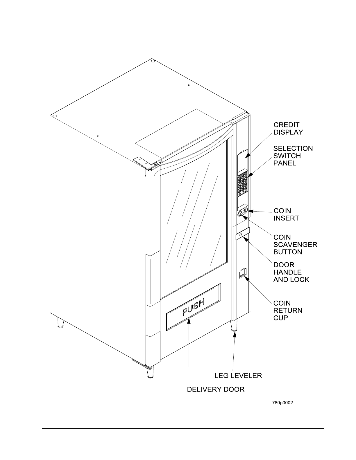
Exterior View
May 2004 1 7800007
Page 8
Introdu cti on Refres hm en t Cen te r Op er ato rs’ Gu ide
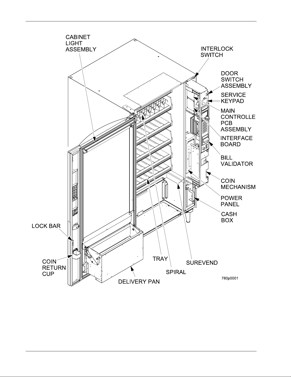
Interior View
7800007 2 May 2004
Page 9

Refreshment Center Operators’ Guide Introduction
Power Requirements
The merchandiser is supplied with a service cord for the country of use and is terminated in
a grounding type plug. The wall receptacle used for this merchandiser must be properly
polarized, grounded, and of the correct voltage. Operating the merchandiser from a source
of low voltage will VOID YOUR WARRANTY. Each merchandiser should have its own
electrical circuit and that circuit should be prote cted with a circuit breake r or fuse conforming
to local regulations.
1. Voltage Check - Place the leads of a voltmeter across the LINE (LIVE) and NEUTRAL
terminals of the wall recept acle. The voltm eter should indicate 110-130 volts AC for 120
volt, 60 Hz locations, or 220- 240 volts AC for 230 volt, 50 Hz locations.
2. Polarity Check - Place the leads of a voltmeter across the LINE (LIVE) and GROUND
terminals of the wall recept acle. The voltm eter should indicate 110-130 volts AC for 120
volt, 60 Hz locations, or 220- 240 volts AC for 230 volt, 50 Hz locations.
3. Noise Potential Check - Place the test leads of a voltmeter across the NEUTRAL and
GROUND terminals of the wall receptacle. The meter should indicate 0 volts AC. A
measurement greater than 1.5 - 2.0 volts AC could result in problems for the
merchandiser's electronic circuitry caused by electrical noise.
Any deviation from these requirements could result in unreliable performance from your
merchandiser.
Unpack the Machine
Remove all packing materials from the interior of the machine. Keep all documents;
warranty cards, etc. Set aside the base plate kit (if present).
May 2004 3 7800007
Page 10
Introdu cti on Refres hm en t Cen te r Op er ato rs’ Gu ide
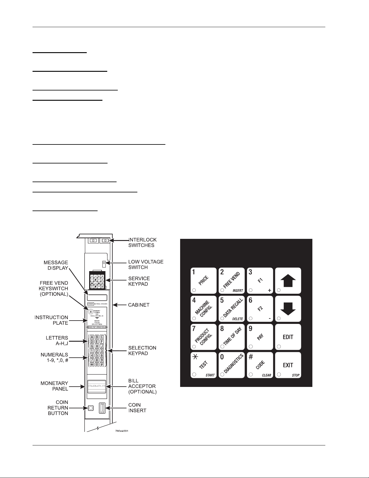
Controls and Indicators
DOOR SWITCH. When the cabinet door is open, this switch turns off the compressor and
evaporator fan.
INTERLOCK SWITCH. (230 volt models only) Turns off the glass heater and display lights
when the cabinet door is open. Pull the switch out to restore high voltage for maintenance.
LOW VOLTAGE SWITCH. Tells the controller software the main door is open or closed.
MESSAGE DISPLAY . This is how the merchandi ser com munic ates wit h the out side wor ld.
Customers can se e messag es about how much money t hey have put into the merchandise r .
The message display also tell s custome rs when a selection is sold out and when vend ing i s
free, inhibited, or discounted. The message display shows you what you are doing when
you program the merchandiser, and can show you what is wrong if there is a failure.
FREE VEND KEYSWITCH (OPTIONAL). This allows someone (other than maintenance
personnel) to set the merchandiser to free vend without opening the door.
SELECTION KEYPAD. The customer uses this keypad to make selections. Maintenance
people may use this keypad during programming.
COIN RETURN BUTTON. Returns any coins paid into the merchandiser prior to a vend.
BILL ACCEPTOR (OPTIONAL). Accepts bills of various denominations, depending upon
the type of bill validator, and how the machine is configured.
SERVICE KEYPAD. The service keypad is located at the top of the monetary panel. It
gives service personnel the means to program, retrieve data from, and view diagnostic
information about, the merchandiser.
SERVICE KEYPAD
7800007 4 May 2004
Page 11
Refreshment Center Operators’ Guide Introduction
F
1
E
P
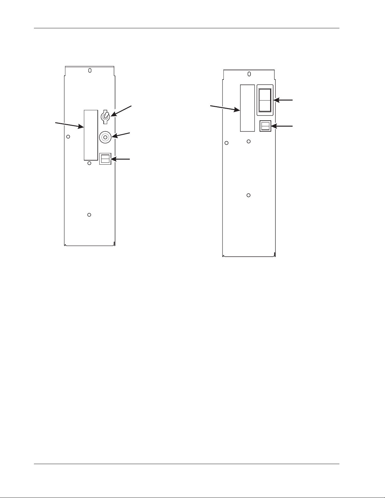
U.S. / CANADA POWER CONTROL PANEL
MAIN CONTROLLER PCB DISPLAY. This display consists of two light emitting diodes
(LED) mounted on the controller PCB.
POWER ON
(LED 1)
HEARTBEAT
(LED 2)
When lit, this red LED indicates electrical power is applied to the
controller PCB.
Whe n flashin g , this r e d LED i ndicates that the control ler PCB is
active, a nd t he software is operating.
NORMAL CONDITIONS:
When the merchandiser is operating normally, you should see a steady red
POWER ON indicator and a flashing red HEARTBEAT indicator. Contact a
service representative if any other condition exists.
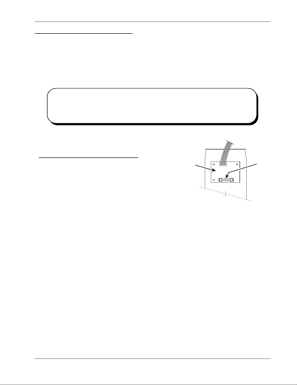
Back Si d e o f U .S . /Canada Po wer Panel.
circuit board mounted on the rear of the power
panel is a DC power supply for the coin
mechan is m. A f us e pr ot ect s t he bo ard c ir cu it ry in
the event of a coin mechanism solenoid failure. If
the coin me c hanism is not working, chec k th is
fuse. If the fuse is blown, a bad coin mechanism
solenoid could be at fault.
The
DC POWER
SUPPLY PCB
OR 110V COIN MECH
˜
BACK SIDE
OF
TOP
AGC
FUS
1 AM
May 2004 5 7800007
Page 12
Introdu cti on Refres hm en t Cen te r Op er ato rs’ Gu ide
Turn the Merchandi s e r ON and OFF
LABEL
I
MAIN
ON
OFF
POWER
SWITCH
MAIN
CIRCUIT
BREAKER
LOW VOLTAGE
CIRCUIT BREAKER
626P0039
LABEL
O
MAIN
POWER
SWITCH
ELECTRONICS
BREAKER
626P0005
US / CANADA POWER PANEL INTERNATIONAL POWER PANEL
• Power to the merchandiser is con trolled by the mai n power switch, loca ted on the
power panel.
• The power panel is on the right side of the merchandiser, behind the monetary
panel.
WARNING
Lethal voltages are present. Unplug the merchandiser before you perform any of the
following tasks:
• Change a fuse
• Change the fluorescent lamp
• Change the lamp starter
• Connect or disco nnect a ha rness (excep t a moto r harness when the tray has bee n
removed)
Failure to do so may result in personal injury.
7800007 6 May 2004
Page 13
Refr eshment Center Operators’ Guide Initi al Set-Up
Section 2: Initial Set-Up
Moving the Merchandiser Through a Narrow Doorway
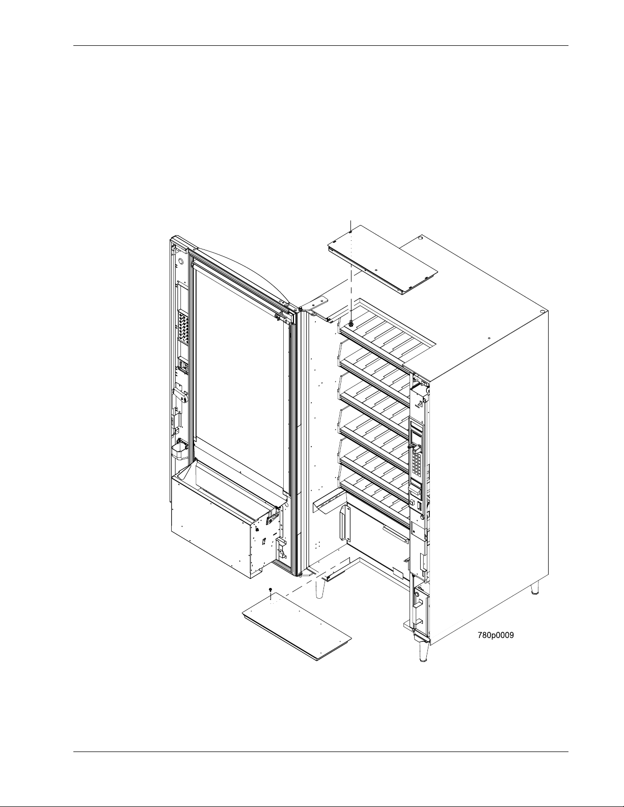
NOTE
If necessary, this merchandiser can be moved through an opening as narrow as 30
inches by removing panels at the top and bottom of the cabinet.
Remove the Bottom and Top Panels:
1. Remove the screws that secure the top and bottom knock-out pane ls to the cabinet.
2. Lift panels upward to remove them from the cabinet.
May 2004 7 7800007
Page 14
Initial Set-Up Refreshmen t Cen te r Oper ato rs’ Gu ide
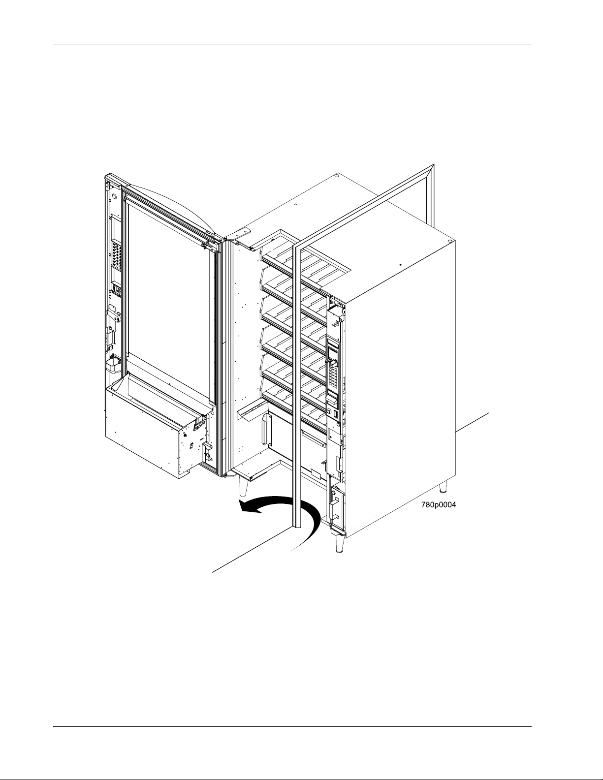
Move the Merchandiser through the Opening:
1. Open the cabinet door and place it square with the left side of the cabinet.
2. Carefully walk the merchandiser through the opening.
Reassemble the Merchandiser:
1. Replace the upper and lower panels.
7800007 8 May 2004
Page 15
Refr eshment Center Operators’ Guide Initi al Set-Up
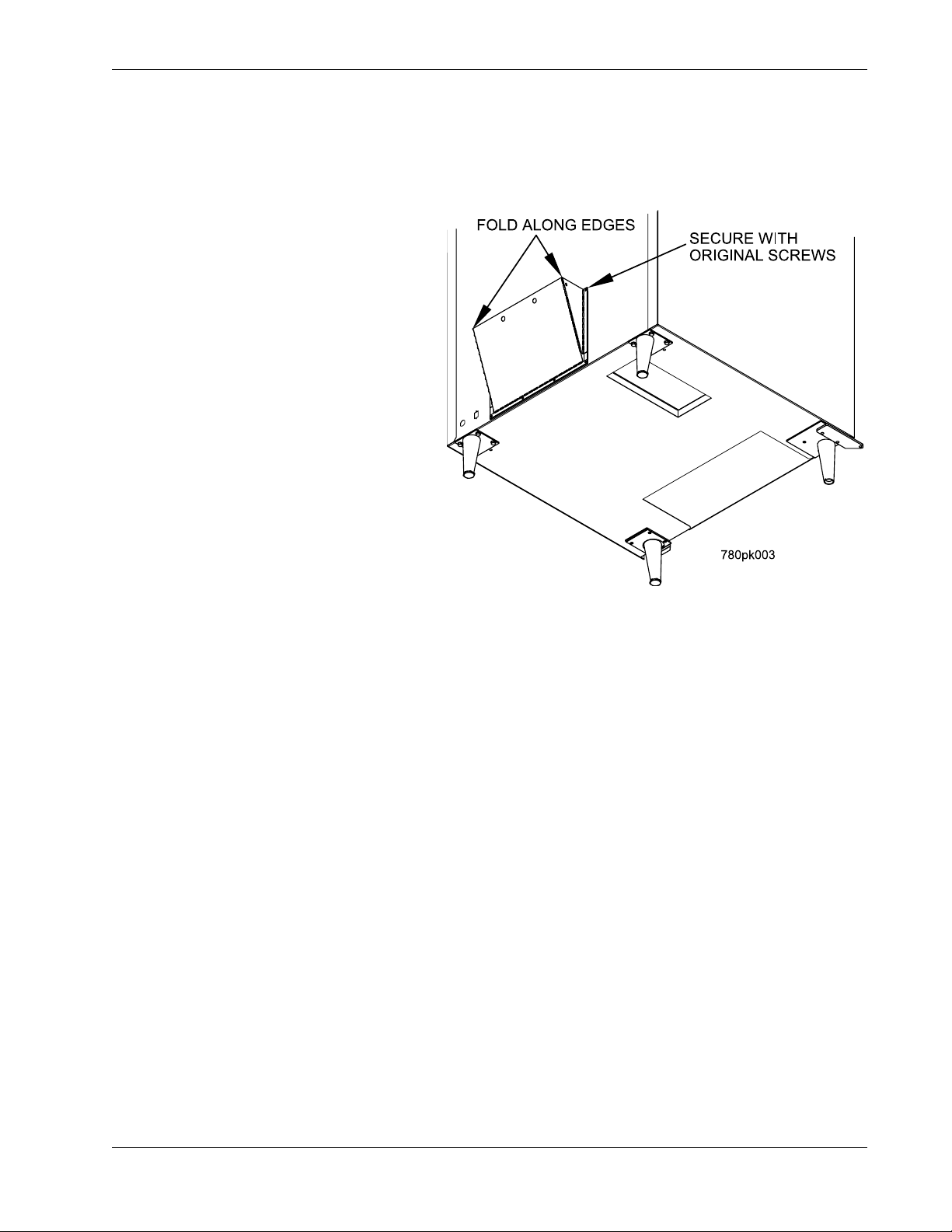
Open the Rear Outlet Diffuser
The rear outlet diffuser vents warm air up and out of the back of the merchandiser, away
from the air inlet ( on the botto m of the cab i net). It is shi pp ed in th e closed posi tion and must
be opened before the merchandiser is put into service.
1. Remove the two screws holding
the upper corners of the diffuser
against the back of the cabinet.
Notice the two unu sed screw hol es
at the corners.
2. Pull the top of the diffuser away
from the cabinet, then bend the
diffuser so that the unused screw
holes align with the holes in the
cabinet.
NOTE:
Wear protective gloves when
bending diffuser to prevent injury.
3. Use the two screws removed in
step one to affix the diffuser to the
cabinet in its new “open” position.
CAUTION
The merchandiser will no t fun c tion properly if the Rear Outlet Dif fuser is not open!
Position the Merchandis e r
Move the merchandiser to its approxima te position. There are certain procedures you
need to perform before it is in its permanent location. Plug in your merchandiser and turn
the power switch to ON.
• You can position this merchandiser anywhere in a bank of machines. It can even
be placed on an end flush against a side wall.
• The merchandiser should be placed at least four inches away from the back wall
(six inches if rear dif fuser is not inst alled). This will provide adequ ate air circula tion
for the refrigeration unit. This will provide adequate air circulation for the
refrigeration unit.
• The merchandiser will operate more efficiently when placed in a shaded location.
• There should be enough room in front of the merchandiser for the door to move
freely.
CAUTION
This machine is only rated for installation at an indoor location.
May 2004 9 7800007
Page 16
Tray Set-Up Refres hm en t Cen te r Op erato r s’ Gu ide
Section 3: Tray Set-Up
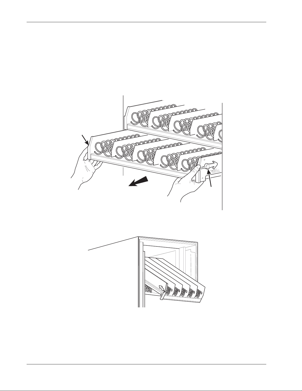
Place a Tray in the Loading Position
1. Place both hands on the tray as shown.
2. Push down on the tray latches with your thumbs.
3a. Bottle Trays: Pull the tray toward you until the slides are fully extended. The bottle tray
can now be loaded--bottle trays do not tilt like snack and candy trays.
3b. Snack and Candy Trays: Pull the tray toward you until you hear and feel the rear tray
rollers drop into a cut-out in the top of the guide rail.
TRAY
LATCH
PULL
TRAY
LATCH
157P0011
4. Continue pulling the tray forward for another inch. You will then be able to tilt the tray
downward into the loading position as shown.The candy or snack tray is now ready for
loading.
SNACK OR CANDY TRAY IN THE LOADING POSITION
NOTE
When the cabinet door is not fully open, the bottom tray will rest on the delivery pan
assembly. Handle the tray with care to avoid scratching the delivery pan assembly.
7800007 10 May 2004
Page 17

Refr eshment Center Operators’ Guide Tray Set-Up
Set up Trays to Ven d Prod ucts
These instructions will guide you through setting up your trays for vending. You will be
asked to determine if your tray can physically hold the products you intend to vend. If not,
you will be directed to other procedures which will help you get them set up. Follow these
nine steps for each tray in your machine:
1. Make sure the tray is in the loading position.
2. Is the column wide enough for the intended product? If so, proceed to the next step.
Otherwise, set up your tray to ven d wid er pr oduct s (see below, this page). When you're
done, return to step 3 in this procedure.
3. Will the products fit between the spiral turns? If so, proceed to the next step.
Otherwise, change the spiral.
4. Will the product pass u nder the tr ay immediatel y above? If so, pro ceed to the next step.
Otherwise, reposition the tray and guides.
5. Will the product touch products on either side? If not, proceed to the next step.
Otherwise, instal l a product spacer.
6. Load products in the tray.
7. Return the tray to the vending position.
8. Install the price rolls.
9. Install the selection ID numbers.
Set Up A Tray To Vend Wide Products
The following steps will help you configure your tray to vend wide products. When you are
done with the entire wide product steps, return to the set-up procedures above.
NOTE:
Does not apply to bottle trays - they cannot be reconfigured.
1. Remove the tray from the merchandiser and place it on a flat surface.
2. Based on the size of the product you want to vend, decide how many spiral positions it
will occupy. Please remember that the leftmost spiral in the group must have an even
ID number (0, 2, 4, etc.) For exa mple, if a product is thr ee spirals wide, th e left spiral will
be ID number 0, and the right spiral will be ID number 2. Be careful how wide you set up
for, because some wide products could get hung up in the delivery door.
3. Remove the column dividers inside the group. In the example of three spiral positions,
you would be removing the dividers between spiral ID numbers 0 and 1, and 1 and 2.
4. If your group only consists of 2 spirals, replace the rightmost motor with a spiral bearing
and gear, and install a gear on the leftmost motor. Skip to step 8.
5. Remove all spirals in the group except the leftmost spiral.
May 2004 11 7800007
Page 18
Tray Set-Up Refres hm en t Cen te r Op erato r s’ Gu ide
6. Do one of the following:
a. If your group has an ODD number of spirals (3, 5, etc.) remove the harnesses from
all motors in the group except the leftmost one. To the rightmost motor, connect the
harness from the mo tor immediately to its left.
b. If your group has an EVEN number of spirals (4, 6, etc.) remove the harnesses from
all mo tors inside the group (leave the harnesses connected to the leftmost and
rightmost motors).
7. Install a spiral at the rightmost position in your group. Make sure it has the same
product capacity and is opposite to the one in the leftmost position.
8. Return the tray to the merchandiser.
9. Electronically couple the motors as needed (see "Couple/Uncouple Tray Motors" on
page 59).
10. Return to step 3 in the "Set up Trays to Vend Products" on page 11.
Stu dy thi s proc edur e before you install a tr ay for the fi rst time; whi le yo u ar e ho lding th e tr ay
you will not be able to see this area.
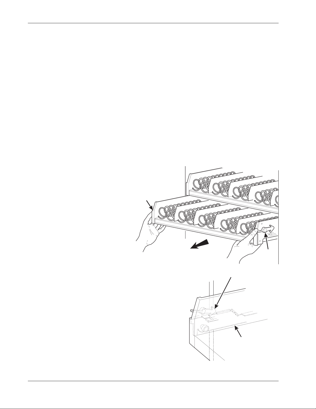
Remove a Snack or Candy Tray
1. Remove all product from the tray.
2. Push down on the tray latches
with your thumbs.
3. Pull the tray toward you until you
hear and feel the rear tray rollers
drop into a cut-out in the top of
the guide rail.
TRAY
LATCH
PULL
TRAY
LATCH
TRAY
LATCH
TRAY
GUIDE
RAIL
7800007 12 May 2004
Page 19
Refr eshment Center Operators’ Guide Tray Set-Up
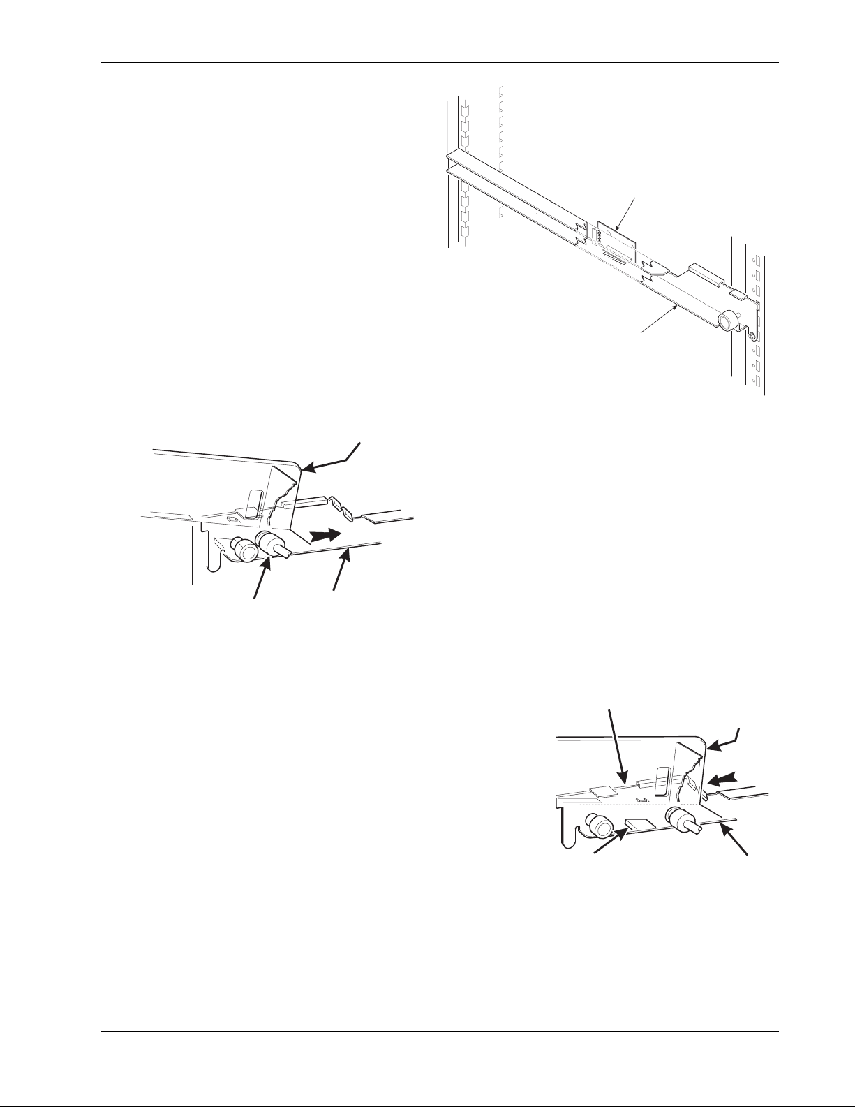
CUT-OUT
REAR OF
E
RAIL
4. Unplug the tray wiring harness from the
PC board mounted on the tray guide rail
IMMEDIATELY ABOVE the tray you are
removing.
PC BOARD
ATTACHED TO
TRAY GUIDE
TRAY GUIDE RAIL
5. Lift up on the tray and slide it toward the
REAR OF TRAY
back. No more than an inch should be needed
6. The tab near the back of the tray should
align with the cut- out in the top of the g uide ra il
as shown.
TRAY
ROLLER
TRAY
GUIDE
RAIL
157P0026
7. Lift the tray clear of the guide rail and out of the
merchandiser.
CAUTION
When the cabinet door is not fully open, use extra
care in removing the bottom tray. Failure to do
so may result in damage to the tray or to
the delivery pan assembly.
TAB
(ON TRAY)
TRAY
TRAY GUID
May 2004 13 7800007
Page 20
Tray Set-Up Refres hm en t Cen te r Op erato r s’ Gu ide
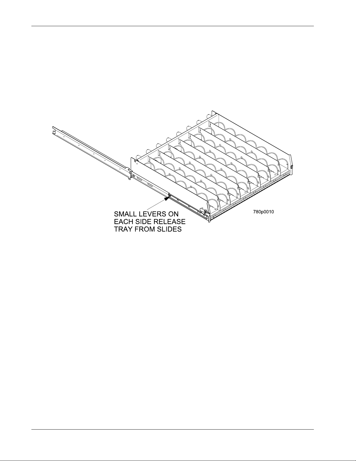
Remove a Bottle Tray
1. Remove all product from the tray.
2. Push down on the tray latches with your thumbs and slide out the tray as far as it will go.
3. Unplug the tray wiring harness from the PC board mounted on the tray guide rail
IMMEDIATELY ABOVE the tray you are removing.
4. Locate a small lever on each s ide of the tray, where it attaches to the slide. The lef t lever
will be up, the right will be down. Press down on the left lever and up on the right lever.
5. Pull the tray towards you, off of the slides.
6. Replace the tray by performing the above steps in reverse order.
NOTE:
It is much easier to replace a bottle tray if you have assistance lining up the
tray rails and slides.
7800007 14 May 2004
Page 21
Refr eshment Center Operators’ Guide Tray Set-Up
DIVIDER
Remove and Install Column Dividers
Note: Not applicable to bottle trays.
1. Push the column divider toward the
back of the tray - .
2. Lift the column divider clear of the tray -
.
2
3. Install the column divider i n the reverse
order of removal.
1
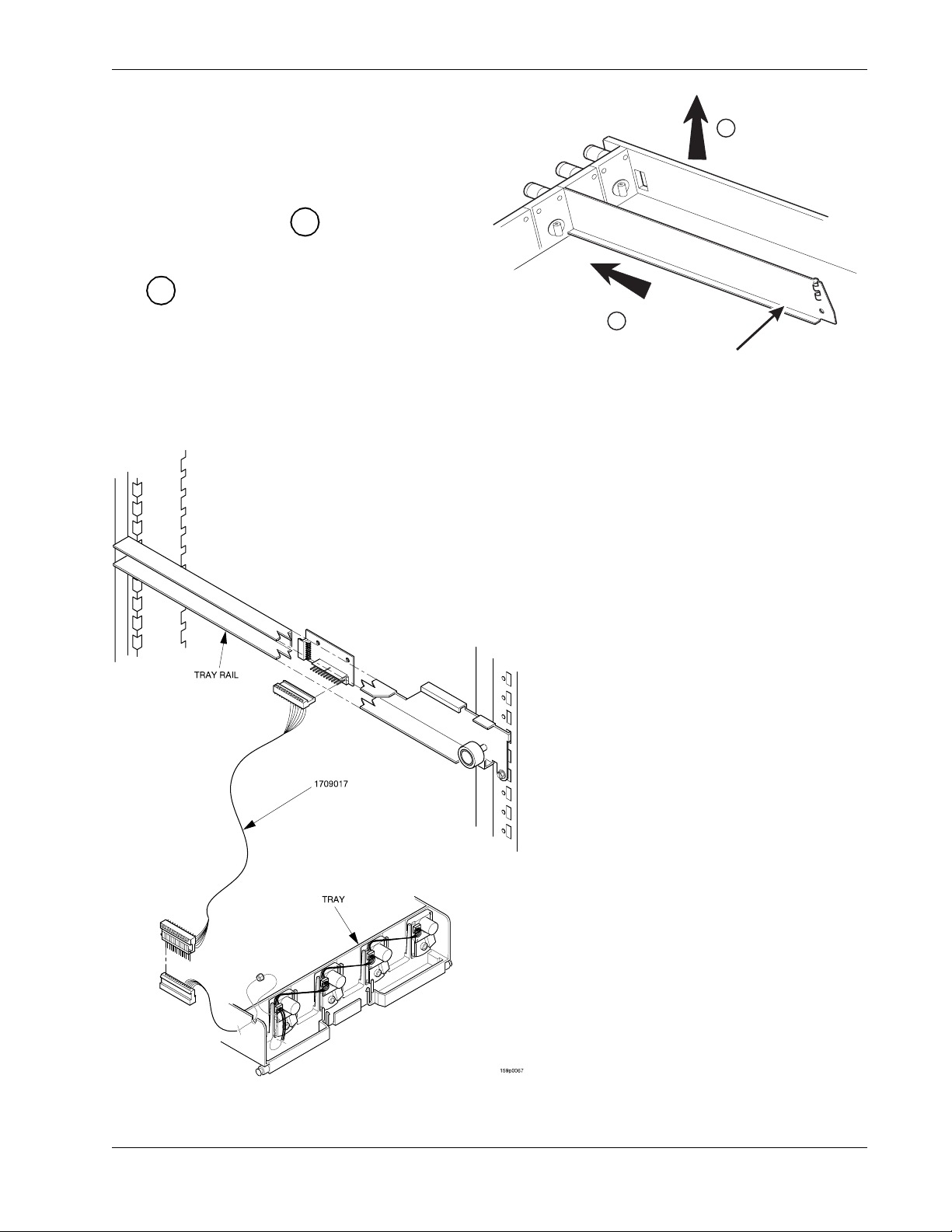
Operate a Tray Outside of the Machine
2
1
COLUMN
Use tray harness extension (P/N
1709018) a vailable from your Nationa l
Vendors Parts department (1-800621-7278). The extension will enable
you to remove the tray from the
machine and still operate the motors
and spirals. Connect it as shown
below:
May 2004 15 7800007
Page 22
Tray Set-Up Refres hm en t Cen te r Op erato r s’ Gu ide
SPIRAL
R
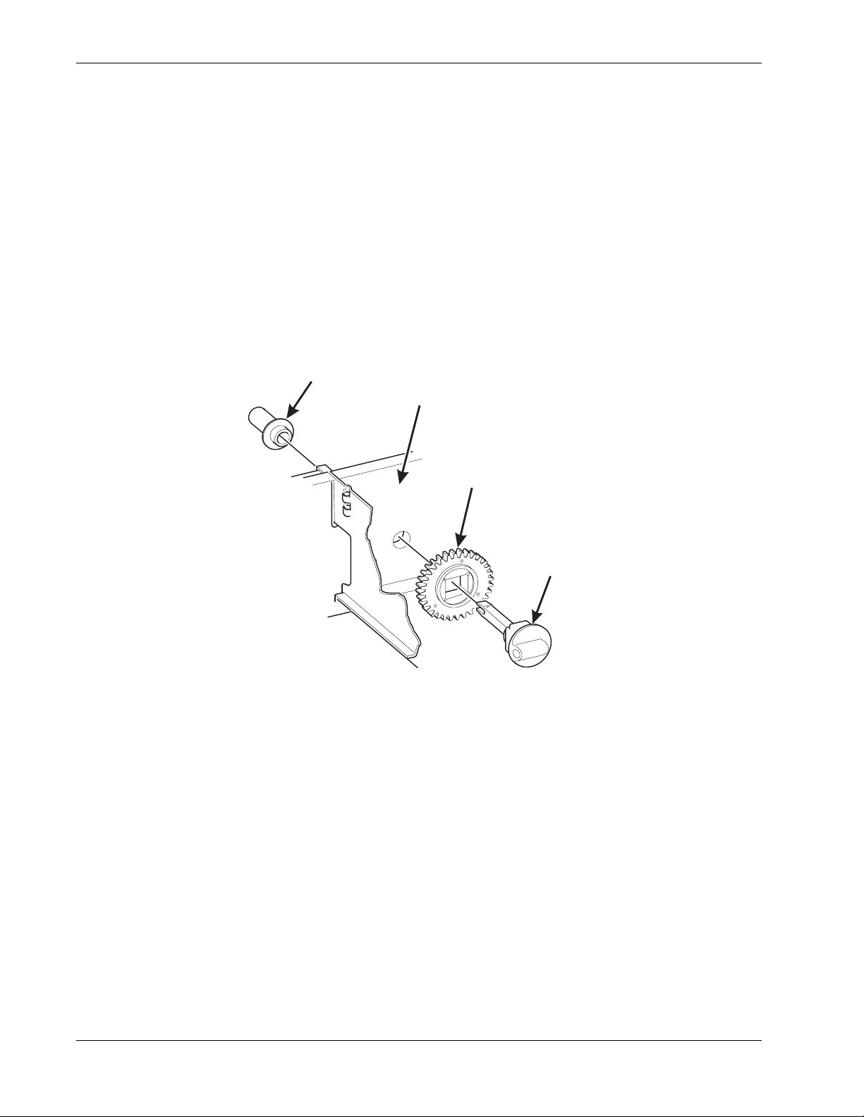
Replace a Motor with a Spiral Bearing
Remove A Motor:
1. Disconnect the harness from the motor.
(See "Connect and Disconnect a Motor Harness" on page 17).
2. Remove the spiral. (See "Remove and Install Spirals" on page 18).
3. Remove the spiral coupler. (See "Remove a Spiral Coupler" on page 19).
4. Remove the motor. (See "Remove and Install a Spiral Motor" on page 20).
5. Install A Spiral Bearing:
a. Put the gear into position in this set-up as shown.
BEARING
BACKWALL
OF TRAY
GEAR
˜
SPIRAL
COUPLE
b. Install the spiral coupler. (See "Install a Gear" on page 21).
7800007 16 May 2004
Page 23
Refr eshment Center Operators’ Guide Tray Set-Up
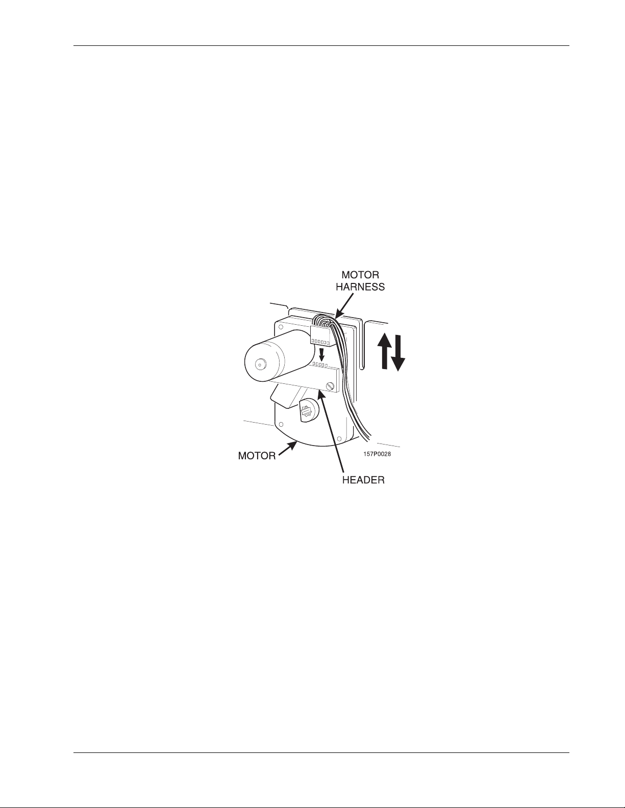
Connect and Disconnect a Motor Harness
CAUTION
To avoid breaking the mot or circuit bo ard, hol d the hea der on the circuit board
whenever connecting or disconnecting a motor harness.
Disconnect a Motor Harness:
1. Pull the harness connector away from the circuit board as shown.
2. Tuck the unused part of the harness out of the way in the trough at the back of the tray.
Connect a Motor Harness:
1. Locate the harness connector for the appropriate tray position.
2. Push the harness connector over the header pins on the motor circuit board as shown.
May 2004 17 7800007
Page 24
Tray Set-Up Refres hm en t Cen te r Op erato r s’ Gu ide
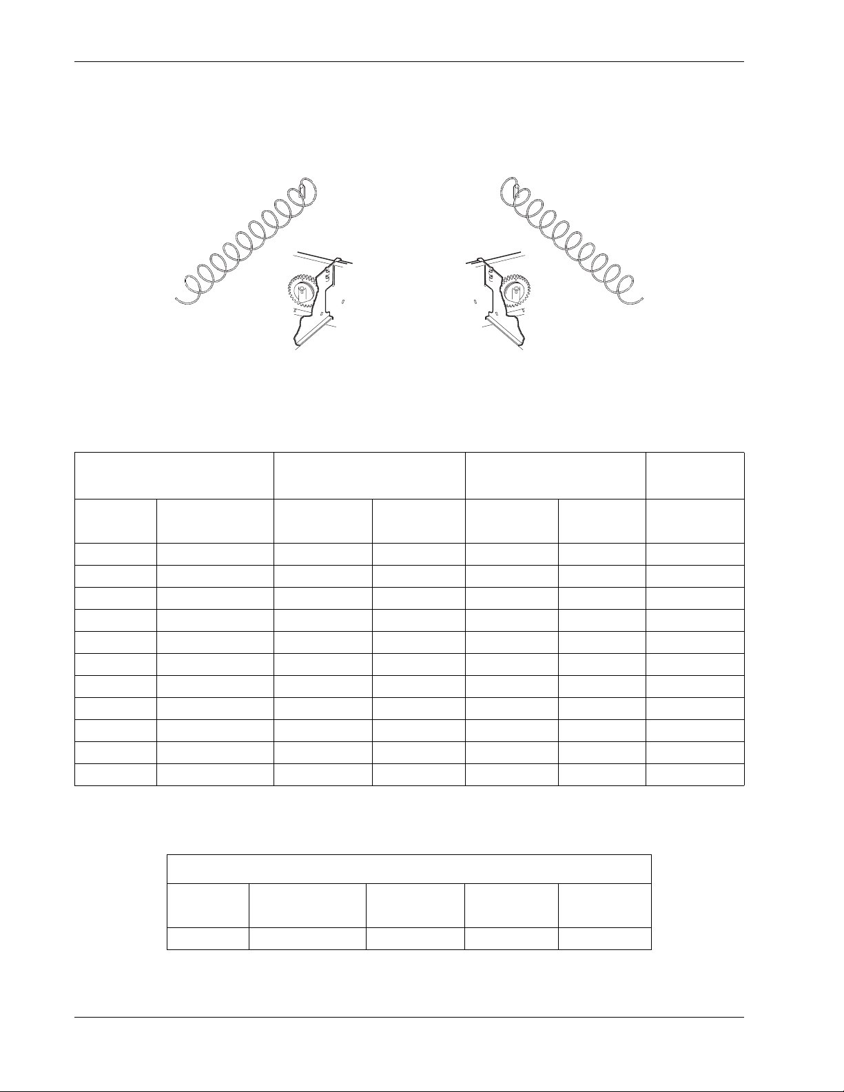
Remove and Install Spirals
• All spirals are the same diameter
• There are two kinds of spirals
Counter Clockwise (left-hand) Clockwise (right-hand)
SNACK AND CANDY TRAY SPIRAL OPTIONS
COUNTER CLOCKWISE
(LEFT HAND)
SPIRAL
COUNT
6 PURPLE 1477103 1477102 1477105 1477104 1477107
8 BLACK 1677247 1677190 1677248 1677189 1477073
9 GRAY 1477152 1477153 1477149 1477150 1477155
11 BLUE 1477023 1477024 1477026 1477027 1457061
13 YELLOW 1477029 1477030 1477032 1477033 1457062
15 RED 1477035 1477036 1477038 1477039 1457063
17 BROWN 1477101 1477100 1477099 1477098 1477106
20 WHITE 1477041 1477042 1477044 1477045 1457064
25 GRE EN 1477047 1477048 1477050 1477051 1457065
30 BLACK 1477053 1477054 1477056 1477057 1477073
38 ORANGE 1477059 1477060 1477062 1477063 1467137
RETAINER
COLOR ASSEMBLY SPIRAL ASSEMBLY SPIRAL RETAINER
CLOCKWISE
(RIGHT HAND)
NOTE
Bottle trays use a 3.25” diameter, 6 count spiral.
BOTTLE TRAY SPIRAL OPTION
SPIRAL
COUNT
6 DARK GREEN 7807011 7807003 4407822
7800007 18 May 2004
RETAINER
COLOR ASSEMBLY SPIRAL RETAINER
Page 25
Refr eshment Center Operators’ Guide Tray Set-Up
LIFT
To Remove a Spiral:
1. Pull forward on the retaining clip and remove the end of
the spiral from the spiral coupler as shown.
2. Remove the spiral from the tray.
SPIRAL
To Install a Spiral:
1. Pull the bottom of the retaining clip toward the front of the
spiral.
COUPLER
PULL
2. Lower the spiral into the tray column and insert the end of
the spiral into the spiral coupler as shown.
SPIRAL
RETAINING
CLIP
3. Release the retaining clip.
Choose a Clockwise or Counterclockwise Spiral
1. The type of spiral used is determined by the column position it will occupy in the tray.
2. Refer to the figure below to find the correct spiral type.
A1 A2
A3
A4
A5 A6
A7
A8 A9A0
Note: Bottle spirals are all clockwise.
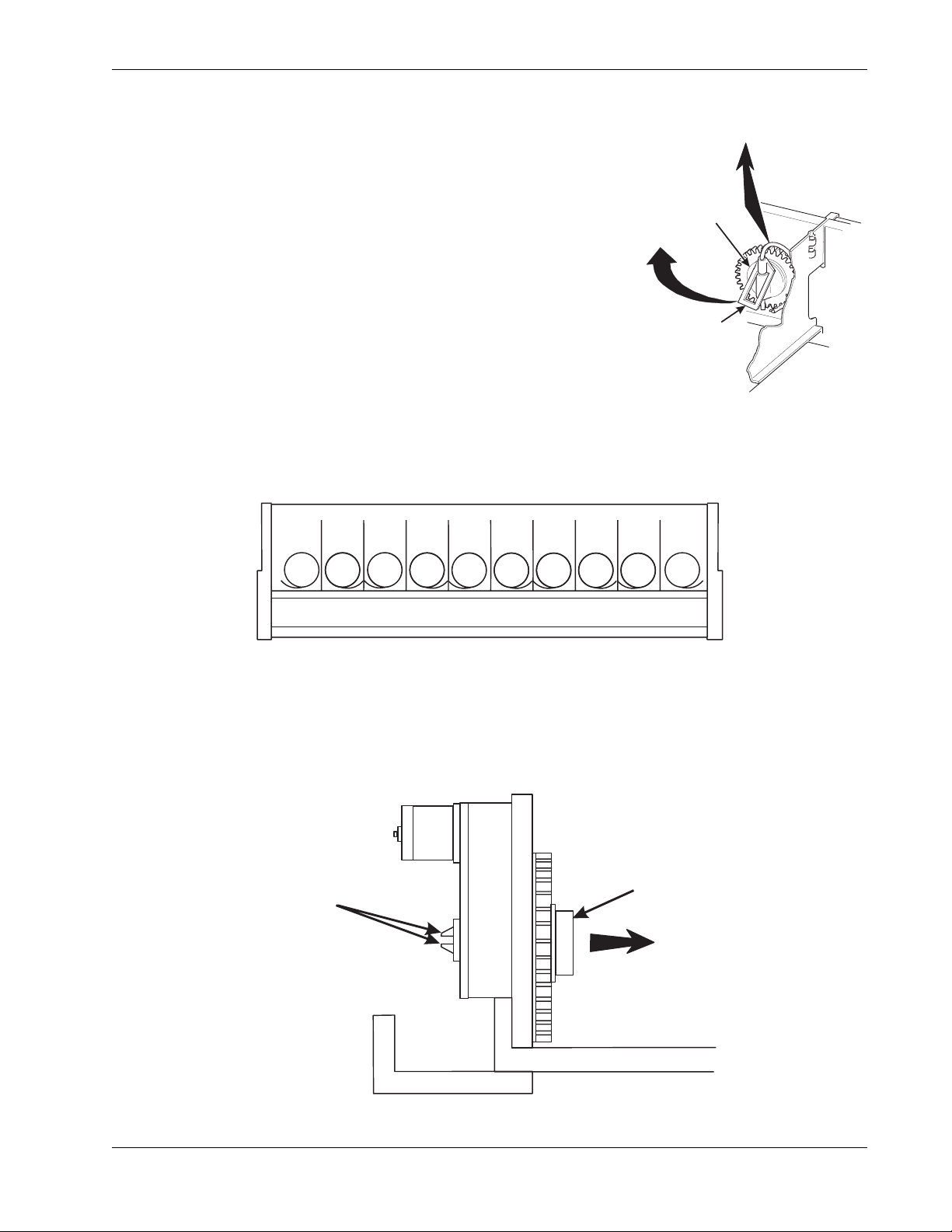
Remove a Spiral Coupler
1. Pinch together the prongs on the end of the spiral coupler as shown.
2. Pull the coupler forward (in the direction of the arrow as shown)
SPIRAL
PRONGS
May 2004 19 7800007
COUPLER
PULL
Page 26
Tray Set-Up Refres hm en t Cen te r Op erato r s’ Gu ide
R
SPIRAL
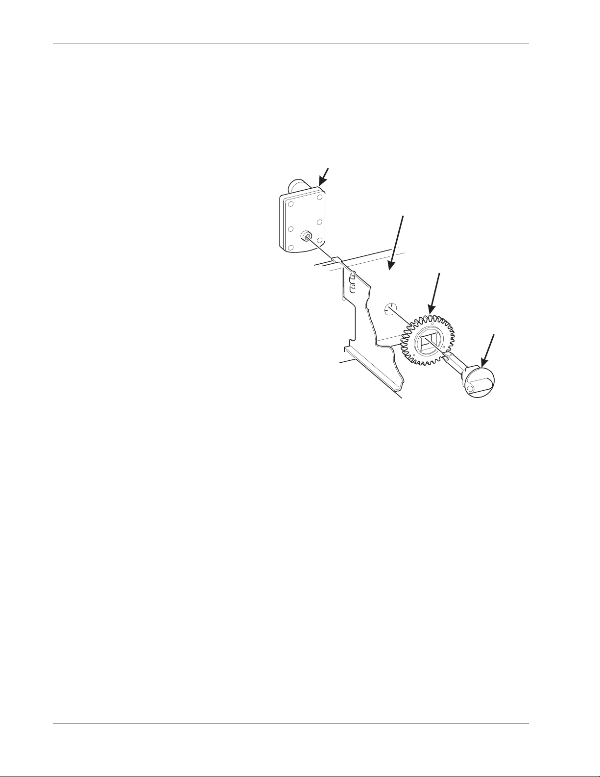
Remove and Install a Spiral Motor
Remove a Spiral Motor:
NOTE
Some steps may already be completed
1. Remove the tray. (See "Remove a
Snack or Candy Tray" on page 12).
2. Disconnect the motor harness.
(See "Connect and Disconn ect a
Motor Harness" on page 17).
3. Remove the spiral.
(See "Remove and Install Spirals"
on page 18).
4. Remove the spiral coupler.
( See "Remove a Spiral Coupler"
on page 19).
5. Lift the motor clear of the tray.
MOTOR
BACKWALL
OF TRAY
GEAR
˜
SPIRAL
COUPLE
6. Return the tray to the merchandiser.
(See "Install a Tray in the
Merchandiser" on page 24).
Install a Spiral Motor:
1. Remove the tray. (See "Remove a Snack or Candy Tray" on page 12).
2. Place the motor in the correct position at the rear of the tray as shown.
3. Place a gear in position if required by this set-up.
4. Install a spiral coupler in the proper orientation. (See "Install a Gear" on page 21).
5. Connect the motor harness.
(See "Connect and Disconnect a Motor Harness" on page 17).
7800007 20 May 2004
Page 27
Refr eshment Center Operators’ Guide Tray Set-Up
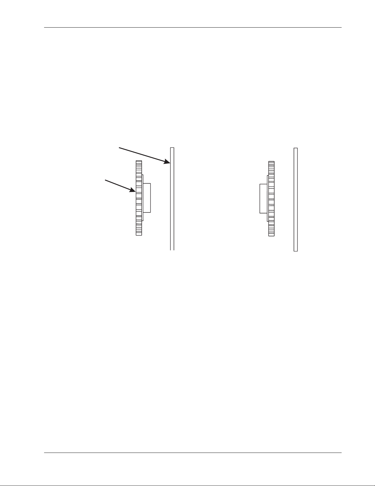
BACK WALL
ORIENTATION 1 ORIENTATION 2
Install a Gear
Use a Gear when:
• Gears are used to mechanically couple the spirals together.
• This happens whenever you have two spirals and only one motor for vending a
selection.
Position the Gear
• Place the gear in between the back of the tray and the spiral coupler.
• There are two possible orientations for the gear:
OF TRAY
GEAR
• There are two rules to follow when orienting gears:
RULE 1 The gears for selections next to each other cannot use the same
orientation.
RULE 2 All gear s for a single selection must use the same orientation.
May 2004 21 7800007
Page 28
Tray Set-Up Refres hm en t Cen te r Op erato r s’ Gu ide
SPIRAL
AS VIEWED FROM FRONT OF TRAY
ONE POSITION
C
ONE POSITION
L
SPIRAL
B
Install a Spiral Coupler
1. Place the gear in position if one is required for this set-up.
When Used with a Motor:
2. Hold the motor in place
and push the spiral
coupler throu gh the motor
gear box until it clicks into
position. Be sure the
spiral couplers are
oriented as shown below.
NOTE
The motor output shaft
opening contains eight facets
to allow the spiral coupler to
be installed in any one of
eight positions.
FRONT VIEW OF
MOTOR OUTPUT SHAFT
MOTOR
Spiral Coupler Orientation
COUPLER
OUNTERCLOCKWISE
FROM VERTICAL
LEFT SPIRAL
COUPLER
When Used with a Coupler Bearing:
3. Hold the coupler beari ng in place and push
the spiral coupler through the bearing until
the coupler clicks into position. Be sure the
coupler is in the proper orientation as
shown.
CLOCKWISE
FROM VERTICA
RIGHT SPIRAL
COUPLER
COUPLER
SPIRAL
EARING
7800007 22 May 2004
Page 29
Refr eshment Center Operators’ Guide Tray Set-Up
Move a Tray Up or Down
This merchandiser can be adjusted to vend taller products. Follow the guidelines below:
• Keep in mind that when you increase the product height available to a tray by
lowering it, you will be decreasing the product height available to the tray below.
• If a tray is in the l owest position, the tray below it should not be i n the high est po siti on.
• If a tray is in the highest position, the tray above should not be in the lowest position.
• You may need to experiment with various tray positions to get the best results for your
products.
CAUTION
The trays in should not be positioned over an open air discharge vent.
NOTE
Tray movement is limited because the tray harness will limit the amount of
travel available to the tray guide rails.
Proceed as follows:
1. Remove the tray from
the merchandiser.
(See "Remove a
Snack or C andy T ray"
on page 12).
REAR GUIDE
MOUNTING CHANNEL
2. Remove the screw th at
secures the right tray
guide rail to the front
guide mounting
PC BOARD
FRONT GUIDE
MOUNTING CHANNEL
channel as shown.
3. Tap up on the guide r ail
CHANNEL
SLOT
and unseat the guide
rail tabs from the
channel slots.
4. Pull the gu ide r ail awa y
from the front and rear
TRAY
GUIDE
RAIL
guide mounting
channels.
SCREW
5. Move the guide rail to
the desired position.
6. Insert the guide rail tabs into the mounting channel slots as shown.
7. Tap down on the guide rail to seat the tabs in the channel slots.
8. Replace the screw that secures the guide rail to the front guide mounting channel.
9. Repeat steps 2 through 8 for the left guide rail.
10. Return the tray to the merchandiser.
( See "Install a Tray in the Merchandiser" on page 24).
1 1. Load product s into the trays, and pe rform te st vends. Make sure the tr ays don't int erfere
with the products you are vending, and that all products vend properly.
May 2004 23 7800007
Page 30

Tray Set-Up Refres hm en t Cen te r Op erato r s’ Gu ide
Install a Tray in the Merchandiser
• Study this procedure before you install a tray for the first time; while you are
holding the tray you will not be able to see this area. Proceed as follows:
1. Insert the tray so that the tray rollers
pass over the tray guide rollers.
REAR OF
TRAY
TRAY
GUIDE
5. Hold the tray up while pushing it toward the
rear. Stop when the tab on the tray aligns
with the opening in the tray guide.
CUT-OUT
TRAY
ROLLER
FRONT OF
RAIL
157P0024
2. Bring the tray rol ler to r est on the tray
guide.
REAR OF TRAY
TRAY
ROLLER
TRAY
GUIDE
RAIL
157P0026
157P0012
TAB
6. Lower the tray until it rests on the tray guide
roller. Push the tray in all the way.
7. The tray latch will fall into the locking
position.
CUT-OUT
REAR OF
TRAY
3. Tilt the tray upward.
4. Connect the tray wiring harness to
the PC board mounted to the guide
rail JUST ABOVE the tray you are
TAB
(ON TRAY)
157P0025
TRAY GUIDE
RAIL
installing.
NOTE:
Does not apply to bottle trays.
7800007 24 May 2004
Page 31

Refr eshment Center Operators’ Guide Tray Set-Up
PRODUCT
DIVIDER
M
G
Install and Remove a Product Spacer
Install a Product Spacer
The product spacer will keep
a tall, narrow product upright.
Shown at right are spacers
and column dividers on both
deep and shallow trays.
Insert the product spac er onto
the column divider as shown.
Adjust a Product Spacer
With product loaded in the
tray , ro tate the p roduct space r
up or down to keep the
product upright as shown.
OUNTING
PINS
SPACER
MOUNTIN
PINS
COLUMN
Remove a Product Spacer
Pull the product spacer
mounting pins from the
column divider.
May 2004 25 7800007
Page 32

Load the Mer ch an dis er Refres hm en t Cen te r Op erato r s’ Gu ide
Section 4: Load the Merchandiser
The color of the spiral coupler (the little plastic tab attached to the rear of the spiral will tell
you how many products will fit in the spiral. (See table below).
NOTE
Another way to determine spiral capacity is to count the spaces in the spiral!
SPIRAL CAPACITY COLOR CODES
SPIRAL
CAPACITY
6Purple
8 Black 20 White
9
11 Blue 30 Black
13 Yellow 38 Orange
15 Red
SPIRAL COUPLER
COLOR
Gray 25 Green
SPIRAL
CAPACITY
17
SPIRAL COUPLER
COLOR
Brown
General Tray Loading:
• See "Product Pusher Usage" on page 28 for spirals with capacity of 11, 13, or 15.
• See "S pi ral Wall Retainer Usage" on p age 27 for spira ls with cap aci ty of 20 , 25, 3 0,
or 38.
• Begin loading pr oduct s a t th e fr ont o f the tr ay an d w ork towar d t he b ack. Posit ion th e
product so the package rests on the tray. DO NOT force a product into a spiral.
• If the fit is too tight or too loose, change the spiral size.
(See "Remove and Install Spirals" on page 18).
• Be sure there are no empty positions between products in each spiral.
Special Considerations:
Bagged Products Position package upright, then push the tops slightly toward the rear of
the tray. Also, (see "Produ ct Pu she r Usage" on page 28).
Thin Packages P osition the package upright.
Also, (see "Spiral Wall Retainer Usage" on page 27).
KitKat The two right-most columns of the cand y tray are desig ned to accept the
KitKat candy bar.
7800007 26 May 2004
Page 33

Refr eshment Center Operators’ Guide Load the Merchandiser
SPIRAL
R
ORIENTATION A
DIVIDER
ORIENTATION B
Spiral Wall Retainer Usage
A spiral wall retainer serves to compress the spiral and make it act like a spring to more
forcefully eject a product. Do some te st vend s and u s e a sp iral wall r et ainer when a prod uct
does not readily leave the spiral.
• Use a spiral wall retainer in the following cases:
• The spiral has a capacity of 20, 25, 30, or 38.
• The product is thin.
• The product is on a candy tray.
• The spiral wall reta iner can also be used with other spirals
and types of products.
• The spiral wall retainer is installed near the front of the
column divider.
• There are two ways to install the spiral wall retainer.
RETAINER
ORIENTATION
AB
WALL
ETAINER
0 and 1 1 and 2
COLUMN
DIVIDER
BETWEEN
THESE
POSITIONS
2 and 3 3 and 4
4 and 5 5 and 6
6 and 7 7 and 8
8 and 9
• To install a spiral wall retainer, insert the retainer in the square slot near the front of
the column divider.
• The spiral wall retainer must be removed in two cases:
• A KitKat bar loaded into either of the two right hand positions of a tray will not
clear the retainer on the column divider between the two positions.
• A product pusher will catch on
a retainer in ORIENTATION A.
May 2004 27 7800007
Page 34

Load the Mer ch an dis er Refres hm en t Cen te r Op erato r s’ Gu ide
T
AS VIEWED FROM FRONT OF TRAY
ONE POSITION
C
ONE POSITION
L
Product Pusher Usage
The product pusher will give the top of a product an
extra tilt to help it fall into the delivery pan.
PRODUC
PUSHER
Use a product pusher in the following cases:
• The spiral has a capacity of 15, 13, or 11.
• The package is non-rigid like bagged
peanuts
The product pusher can also be used with other
spiral and types of products.
A bag of product pushers has been shipped with the
merchandiser. Additional product pushers are
available from the National Vendors' parts department (800-621-7278). To use a product
pusher, snap it on the spiral as shown. You can adjust the product pusher by moving it
around on the spiral to achieve the best vending results.
Confi g ur e t h e
Merchandiser to vend
OUNTERCLOCKWISE
FROM VERTICAL
CLOCKWISE
FROM VERTICA
“Lunch Buckets”
Because of the weight and shape of the
package, National Vendors
recommends that this product be
vended only from the bottom tray.
To vend this product, two adjacent
positions must be coupled together.
The left spiral coupler should be
installed one position counterclockwise
from the vertical position.
FOOD SELECTIONS
LOADED IN SPIRALS
The right spiral couple r should be installed one position
clockwise from the vertical position.
Replace the current spirals with six-count spirals.
These are available from the National Vendors parts
department. (See "Remove and Install Spirals" on
page 18). A pad can be installed in the bottom of the
delivery pan to qui et and cushion product delivery. This
part is available from the National Vendors parts
157P0039
department. Load "Lunch Bucket" products as shown
at left.
LEFT SPIRAL
COUPLER
RIGHT SPIRAL
COUPLER
7800007 28 May 2004
Page 35

Refr eshment Center Operators’ Guide Load the Merchandiser
TOP SHELF
Configure the Merchandiser for Vending "Top Shelf"
National Vendors recommends that this product be vended from a candy tray.
1. Move the tray so the package can be loaded standing on its left or right edge.
( See "Move a Tray Up or Down" on page 23).
2. The following steps must be completed for three adjacent positions on the tray:
NOTE
The left-most position in the group of three must be an even numbered position.
3.
4.
DISCONNECT THIS
MOTOR CONNECTOR
6.
TO THIS MOTOR
LEAVE THIS MOTOR
CONNECTOR ALONE
1. REMOVE COLUMN
DIVIDERS
2. REMOVE
SPIRALS
5.
MOVE CONNECTOR
FROM THIS MOTOR
7. INSTALL AN 11-COUNT LEFT HAND
SPIRAL IN THIS POSITION
INSTALL AN 11-COUNT RIGHT-HAND
8.
SPIRAL IN THIS POSITION
157P0040
NOTE
If the motor harness disconnected in step 5 does not reach, use the motor skip harness, (P/
N 1599024), available from the National Vendors Parts Department (800-621-7278).
PRODUCT
3. Couple the left motor to the right motor. (See "Couple/Uncouple Tray Motors" on
page 59).
4. Load the "Top Shelf" products as shown.
May 2004 29 7800007
Page 36

Load the Mer ch an dis er Refres hm en t Cen te r Op erato r s’ Gu ide
Return the Trays to the Ven ding Posit ion
1. Lift the tray until it is parallel to the floor as shown.
TRAY
LATCH
PULL
TRAY
LATCH
157P0011
2. Push the tray toward the back of the cabinet. The tray latches on the sides of the tray
will lock into position.
TRAY
LATCH
TRAY
GUIDE
RAIL
157P0027
7800007 30 May 2004
Page 37

Refr eshment Center Operators’ Guide Load the Merchandiser
Install and Set Price Labels
• Price rolls are printed on coiled strips as shown in the illustration below. (The dollar
and cents rolls are factory installed.) If you use another type of currency, you will find
the appropriate price rolls in the plastic bag that contained this manual.
• There are two types of price rolls:
Dollar roll 1 to 12, increments of 1
Cents roll 00 to 95, increments of 05
• Remove the price roll s as re quire d, and i nst all the appropriate ones for your currency.
DOLLAR ROLL
CENTS ROLL
157P0043
Install Price Labels:
There are three pairs of slots in the front of the can unit for each position. Install per this
example:
1. Insert the dollar roll in the left-most pair of slots as shown if the price is $1.00 or more.
2. Insert the cents roll in the center pair of slots as shown.
PRESS TOP OF ROLL
PAST FLEXIBLE TAB
NEAR TOP EDGE
3.The low-number end of the roll
goes in the top slot and the highnumber end of th e roll g oes in the
bottom slot.
INSERT BOTTOM OF ROLL
THROUGH SLOT ALONG
BOTTOM EDGE
May 2004 31 7800007
157P0044
Page 38

Load the Mer ch an dis er Refres hm en t Cen te r Op erato r s’ Gu ide
Adjust the Price Roll:
You can set selection prices within the following range:
Minimum price $.00
Maximum price $99.99
Increment $.05
1. Use your thumb as shown to move each price roll up or down as needed to set the
desired price.
NOTE
You will see the word STOP near either end of the roll.
157P0045
Selection ID numbers are printed on clear plastic sheets. You will find these in the plastic
bag that contained this manual. You will need to separate them along the scored lines
between the selections. BE CAREFUL when doing this, as it is easy to split the labels.
Install the Selection ID Numbers:
1. Press together the two long edges of the selection ID label.
2. Snap the selection ID label into position on the front of the tray as shown.
DOLLAR
PRICE ROLL
CENTS
PRICE ROLL
SELECTION
IDENTIFICATION
157P0059
7800007 32 May 2004
SELECTION
IDENTIFICATION LABEL
Page 39

Refr eshment Center Operators’ Guide Load the Merchandiser
See the figures below for snack and candy tray positions.
MOTOR POSITION
TOP T RAY TRAY AA0A1A2A3A4A5A6A7A8A9
TRAY BB0B1B2B3B4B5B6B7B8B9
BOTTOM TRAY TRAY CC0C1C2C3C4C5C6C7C8C9
NOTE
This example shows a 3- tray merchandiser.
Some merchandisers can have up to 6 trays.
Examp le of a Basic
Snack Tray ID La bel to Use
A0 A2 A4 A6 A8
Examp le of a Basic
Candy Tray ID Label to Use
A1 A2
A3
A4
A5 A6
A7
A8 A9A0
May 2004 33 7800007
Page 40

SureVend™ Refreshmen t Cen te r Op er ato r s’ Guide
Section 5: SureVend™
The SureVend™ product detection system consists of ten infrared light emitters and ten
infrared light detector s that scan the product delivery ar ea with a p attern of crisscrossed light
beams. While the machine is idle, the SureVend™ system is constantly calibrating itself for
optimum performance in all temperature, humidity, dust, and alignment conditions. The
SureVend™ detection system is used by the controller to assure that the selected product is
delivered.
• When a customer makes a selection, the controller checks that the SureVend™
detection system is ready and tells it to begin scanning for the product. Different
scanning patterns are used depending upon the size and shape of the product.
• The vending machine controller then starts the delivery motor and constantly
checks the SureVend™ system for detection of the delivered product.
• If no product del ivery is d etected, the controll er continu es to run the deli very moto r
for up to three revolutions, pausing momentarily at the home position of each
revolution of the motor.
• If no product is detected after the third revolution, the selection is marked as
empty and the customer's credit is optionally restored to make another selection
or is automatically returned.
• If product delivery is detected before the delivery motor has come to the home
position for the first time, the delivery motor continues running to its home
position.
• If the delivery motor has already p assed the first home position, the motor will stop
immediately upon product detection to avoid the possibility of vending a second
product.
NOTE:
A fatal malfunction in the SureVend™ detection system during the
vend is treated the same as a product delivery. It is assumed
that the malfunction is due to tampering or vandalism.
Anti-Jackpot provides protection against unforeseeable cheating of the Sure-Vend™
system. If a certain number of SureV end™ em pty conditions occur, Sure-Vend™ will disable
itself for a few minutes. A SureVend™ empty condition occurs when product delivery is not
detected and the customer's money is restored or returned. Both the number of
SureV en d™ empty conditions required to disable SureVend™, and the number of minutes it
remains disabled, are both configurable by the operator (see "Set Up the SureVend Anti-
Jackpot Feature" on page 58).
Once Anti-Jackpot is triggered, the SureVend™ system will be turned off for a certain
number of minutes so that money can no longer be refunded because of vend failure and
thus discourage a thief from remaining. While SureVend™ is disabled, machine will either
revert to home switch operation or go out of service, depending on other selected options
(see "Set Up Basic SureVend™ Options" on page 58).
Once the Anti-jackpot time has elapsed, SureVend™ is re-enabled. The total number of
SureVend™ empty selections, the number of anti-jackpot occurrences, and the date and
time of the most recent occurrence are recorded.
7800007 34 May 2004
Page 41

Refr eshment Center Operators’ Guide Health Contro l
Section 6: Health Control
NOTE:
The following section applies only to the 780 Refreshment Center.
The 781 Refreshment Center does not have Health Control software.
Refreshment Centers configured for Refrigerated Food operation (see "View Or Set
Machine Configuration" on page 57), will have electronic health shutoff control software.
Health Shutoff Control software is required by state and local health authorities and is a
requisite for NAMA approval for perishable food vending.
Health Shutoff Control prevents the merchandiser from vending product that could be
spoiled. It monitors the temperature within the cabinet, and will automatically go into an outof-service mode should any of the following conditions occur:
• The temperature of the refrigerated cabinet does not fall to 41° F (5° C) within 30
minutes after the door of the refrigerated cabinet is closed.
• The temperature of the refrigerated cabinet does not fall to 41° F (5° C) within 30
minutes after a defrost.
• The temperatur e of the cabinet rises above 41° F (5° C) for more than 15 mi n utes
without the door of the refrigerated cabinet having been open, except within 30
minutes of a defrost.
• For testing purposes, the temperature of the cabinet rises above 41° F (5° C) for
at least one second with the refrigerated door open.
When the health shutof f control is triggered, the display will read
When the mone ta ry d oor is opened, the message chang es to
maximum cabinet temperature reached are displayed. If the refrigerated cabinet door is
opened and then closed, the health control timer will reset and the refrigeration system will
have another 30 minutes to cool the cabinet below 41° F (5° C).
The out-of-service condition may occur during initial setup, as it will take time for the
refrigeration system to cool the cabinet the first time. Therefore, National Vendors
recommends leaving the refrigerated compartment empty until the cabinet temperature is
low enough to satisfy the health shutoff control.
Health Control will not be operative for Refreshment Cente rs configu red for Chille d vending
(see "View Or Set Machine Configuration" on page 57). Perishable food must only be
sold from a merchandiser configured for Refrigerated Food operation. Vending perishable
food from a chilled merchandiser will violate state and local health regulations.
T EMP ORAR Y OU T OF SE RVIC E
HC.ER
, and the date, time, and
.
May 2004 35 7800007
Page 42

Health Control Refreshment Center Operators’ Guide
Test the Health Control
Use this procedure on model 780 merchandisers configured for refrigerated food to verify
the operation of the Health Control Automatic Shutoff circuitry. The purpose of the Health
Shutoff Contro l is to disable the vending mechanism whenever the machine does not
maintain the air temperature in the food storage compartment at or below 41oF (5oC). The
temperature shutoff requirement does not apply for 30 minutes after filling, servicing or a
defrost cycle.
NOTES:
a. The Automatic Health Shutoff Control timer resets every time the cabinet door is
closed.
b. The internal cabinet temperature can be viewed on the credit display by pressing
.
1. Check the temperature of the food compartment by pressing to ensure that the
machine is not in the 30-minute recovery period that occurs after the door is closed
following filling, servicing or after a defrost cycle. If the machine is in the 30-minute
recovery period, the time remaining will appear on the display. Before proceeding, wait
until the recovery period ends.
2. Open the main door a minimum of 45 degrees to allow the food compartment
temperature sensor to warm. Observe the cabinet temperature on the credit display by
pressing the button. When the temperature on the display rises to 42o F (5.5oC),
the message "T
Temporary Out of Service
" will display. This verifies that the vending
mechanism of the machine has been disabled as required. With the door open, the
sensor temperature will typically reach 42o F (5.5oC) in less than 5 minutes.
3. Press the button and the message "HCER" (Health Control Error) will display.
This is the message a service person would observe after opening the door.
4. Close the main door. You may observe the recovery time and temperature by pressing
again.
7800007 36 May 2004
Page 43

Refreshment Center Operators’ Guide Final Installation
Section 7: Final Installation
Move the merchandiser to its final position:
•Perform “Open the Rear Outlet Diffuser” on page 9 before placing the merchandiser
into its final position.
• You can position this merchandiser anywhere in a bank of machines. It can even be
placed on an end flush against a side wall.
• The merchandiser should be placed at least four inches away from the back wall (six
inches if rear dif fuser is n ot inst alled) . T his will provide a dequa te a ir circu lation fo r th e
refrigeration unit.
• The merchandiser will operate more efficiently when placed in a shaded location.
• There should be enough room in front of the merchandiser for the door to move
freely.
WARNING
This machine is only rated for installation in an indoor location.
Level the Merchandiser
1. Use a spirit level to adjust th e legs until the
cabinet is level from side to side and front
to back.
NOTE
A slight slope from front to back will
improve the draining of condensate from
merchandisers with refrigerating units.
When the merchan diser is par t of a bank of
machines, level it in refere nce to the other
machines. After leveling is complete,
check that the door operates easily.
May 2004 37 7800007
Page 44

Final Installat io n Refr es hm en t C enter Operator s’ Gu ide
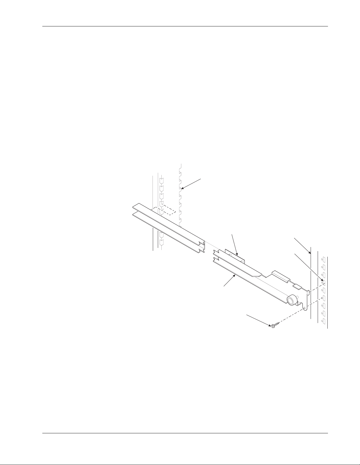
Install the Base Plate
Refer to the figure below while completing the following procedures:
WARNING
Do not move the cabinet while the hex head screws and/or carriage bolts are
loosened. The cabinet would be unstable and could tip and cause injury.
1. Loosen the left leg assembly hex screws to allow mounting a base plate bracket.
2. Secure one of the base plate brackets to the leg assembly and tighten the hex screws.
3. Loosen the right leg assembly hex screws to allow mounting the other base plate
bracket.
4. Secure the other base plate bracket to the right leg assembly using the two hex head
screws. Tighten the hex head screws.
5. Insert the short arms of the slides into the hinged tabs of the base plate. Position the
slide so the notch near the short arm is on the bottom side.
6. Insert the long arms of the slides into the base plate brackets.
7. Insert and secure a cotter pin through the hole in the back of each of the slides.
8. Push the base plate toward the merchandiser cabinet. The front tabs of the base plate
brackets should seat in the notches in the long arms of the slides.
7800007 38 May 2004
Page 45

Refreshment Center Operators’ Guide Final Installation
LOCK
LEVER
E
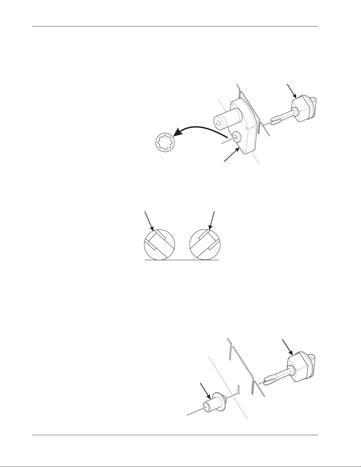
Install the Lock Cylinder
Install an optional lock cylinder in the
merchandiser as follows:
1. Position the lift handle lock lever
as shown.
SPRING
2. Depress the lock spring at the
square hole of the lock cylinder
SQUAR
HOLE
receptacle and pull the lock
springs out through the front.
3. Position the lock cylinder as
shown. Depress the spring
KEY
LOCK
CYLINDER
loaded lock pin.
4. Push the cyli nder into th e cylinder
receptacle in the lever. The pin
shou ld snap into the square hole.
5. If the cylinder pin does not seat in the square hole, press against both ends of the lock
cylinder. Rotate the cylinder until the pin snaps into place.
6. Leave the door open and test the lock mechanism with a key. Do not close the door
until you are certain the key will unlock the lock.
Install the Optional Cash Box Lock
Remove the cash box from the merchandiser.
1. Assemble the lock as shown in the illustration
to the right.
2. Return the cash box to the merchandiser.
LOCK
CYLINDER
LOCK BAR
SCREW
NUT
WASHER
May 2004 39 7800007
Page 46

Final Installat io n Refr es hm en t C enter Operator s’ Gu ide
Set Up the Coin Mechanism
If the changer is not a MARS TRC 6000, proceed to LOADING THE COIN MECHANISM
If the Changer is a MARS TRC 6000, you must set the high quarter switch.
Set the Quarter Switch:
QUARTER SWITCH
POSITION
LOW
HIGH
quarters. The rest are
will store 69 quarters.
ACTION
The coin mechanism
will only sto re 6
sent to th e c oin box.
Fewer qu art ers are
available for change.
The coin mechanism
More quarters are
available for change.
Load the Coin Mechanism
Once you arrive at the step s that tell you how to setup your coin mechanism, ple ase perform
the following steps:
1. Plug the power cord into the electric outlet and turn ON the main power switch.
2. Press , and press once. Press until either
DUMB MECH
or
MDB MECH
displays (depending upon which coin mech type you have).
3. If you chose
procedure. If you chose
MDB MECH
in the previous step, go to step 4 and perform the rest of this
DUMB MECH
in the previous step, fill the coin tubes with coins.
Make sure the coins are not shingled. You are now finished setting up your coin mech.
Do not perform the rest of this procedure.
4. Press until the standby message is displayed, then press .
5. Insert at least 20 coins of each denomination through the coin chute. Con tinue to fill the
coin tubes either through the coin chute or the tops of the tubes.
6. Visually check the coin tubes to make sure coins are not shingled.
7. Press .
8. If credit is still shown in the display, turn the machine power OFF, then back ON.
7800007 40 May 2004
Page 47

Refreshment Center Operators’ Guide Final Installation
Operational Readiness Check
1. Perform test vends on all selections.
2. Do any of the snack or candy products catch on the tray and fail to vend? If not, skip to
step 3. If so, perform the following procedures on the affected areas until all products
vend properly:
a. Install and/or adjust a product spacer (See "Install a Product Spacer" on page 25).
b. Install a product pusher (See "Product Pusher Usage" on page 28 ).
c. Install and/or remove spiral wall retainers (See "Spiral Wall Retainer Usage" on
page 27).
d. Perform the appropriate spiral anti-hang-up procedure(s).
3. Test the operation of the coin mechanism.
4. Test the operation of the bill validator.
5. Return all test vended products to the trays.
Spiral Indexing Procedure (One Spiral, One Motor)
The spiral indexing procedures involve rotating spirals one position at a time until the
product vends properly.
1. Home all the motors.
2. Remove the effected spiral.
3. Is the coupler in the proper position?
NO - Move the coupler to the position as shown in "Install a Gear" on page 21. Go to
step 4.
YES - Move the coupler to the next clockwise position (if it's on a right-hand motor), or
the next counterclockwise position (if it's on a left-hand motor). Go to step 4.
4. Replace the spir al.
5. Perform a test vend (see the previous page).
6. Did the product hang up?
NO - You're finished. Continue to test vend the remaining selections until everything
works right.
YES - Go to step 7.
7. Did you previousl y mo ve the coupler to th e next clockw ise or counter clockw ise po siti on?
NO - Move the coupl er to the n ext clockwise p osition (if it's on a righ t-hand mo tor), or the
next counterclockwise position (if it's on a left-hand motor). Return to step 6.
YES - Return to step 2 in the operational readiness check and try another procedure.
Do not move the coupler again.
May 2004 41 7800007
Page 48

Final Installat io n Refr es hm en t C enter Operator s’ Gu ide
Spiral Indexing Procedure (Two Spirals, One Or Two Motors)
The spiral indexing procedures involve rotating spirals one position at a time until the
product vends properly.
1. Home all the motors.
2. Remove the left hand spiral of the affected pair.
3. Is the coupler in the proper position?
NO - Move the coupler to the position as shown in "Install a Gear" on page 21. Go to
step 4.
YES - Move the left coupler to the next counterclockwise position. Go to step 4.
4. Replace the left hand spiral.
5. Remove the right hand spiral, spiral coupler, and gear (if used) of the affected pair as a
unit.
6. Rotate this unit until the right hand spiral mirrors the position of the left hand spiral.
7. Replace the right hand spiral, spiral coupler, and gear (if used).
8. Perform a test vend (see the previous page).
9. Did the product hang up?
NO - You're finished. Continue to test vend the remaining selections until everything
works right.
YES - Go to step 10.
10. Did you previously move the left hand coupler to the next counterclockwise position?
NO - Remove the left hand spiral of the affected pair. Turn the left spiral coupler to the
next counterclockwise position. Return to step 4.
YES - Return to step 2 in the operational readiness check and try another procedure.
Do not move the coupler again.
Test the Bill Validator
1. Insert a $1 bill into the validator.
2. Push the coin return button.
THE BILL V ALIDATOR IS IN THE ESCROW MODE - No money is returned - you must
make a selection in order to receive any change. Go to step 3.
THE BILL VALIDATOR IS NOT IN THE ESCROW MODE - You should receive four
quarters in change. Go to step 3.
3. Make a selection. The correct selection should be vended and correct change should
be returned.
7800007 42 May 2004
Page 49

Refr eshment Center Operators’ Guide Programming Intro
Section 8: Programming Intro
Some setup, test, and maintenance operations are computer controlled. The control panel
switches and the selection panel switches regulate these operations.
Control Panel
Selection Panel
157p0248
The Displays
The 10-character display performs two functions, and is referred to in this book as "the
display":
1. It shows the customer's selection and how much credit is in the machine, as well as the
ready, service, and time of day messages.
2. It provides information and feedback to the service person during maintenance.
DISPLAY
May 2004 43 7800007
Page 50

Programming Intro Refreshment Center Operators’ Guide
T
y
n
k
y.
ill
g
n
r
to
re
The Function K e y s
The keys on the control panel can have up to three functions:
THE PRIMARY PURPOSE
this is the main job of the ke
from the stan dby message, it w
allow yo u to en t er a pr ogra mmin
HE NUMBER
ou might be asked to enter a
umerical value. pressing this
ey will enter a "5".
mode. in this example, you ca
view stored sales data.
THE SECONDARY PURPOSE
this is the key's "second job". fo
example, this key can be used
delete a character when you a
editing custom messages.
Other Keys
The MOVEMENT keys on the con trol p anel let you m ove insi de a mod e, and back an d forth
between modes. To see how thes e keys let you m ove around , study the flow d iagram on the
next page.
The up and down arrow keys are your "legs", which let you move up and down
the list of tasks. These keys are what let you continue from one step to the next
in programming procedures.
This is you r "activate" or "ch oose" key. It "opens a door " to additional
information and lets you begin a programming task once you are inside of a
mode. Sometimes, it is used as a toggle switch to show you your choices
during a programming task.
This is your "end" key. Pressing it one or more times will move you back to the
start of the mo de, or all the way back to the sta ndby messag e.
One Last Thing:
When you see the word CONTINUE at the end of a function, it means to press until
you return to the standby message.
7800007 44 May 2004
Page 51

Refr eshment Center Operators’ Guide Programming Intro
Control Panel Switches Explained
Each of the control panel switches ha s one or more jobs to do. T his list will give you a short
overview of those jobs.
Press this button to pu t your machine into the Price Setting mode. You can see
maximum and minimum machine prices, and change prices for entire machine,
entire tray, or individual selection.
Press this button to set up how the Free Vend mode will operate.
Press to view the temperature of a cold unit (if applicable), or software version
number.
Press this button to:
• Se lec t dis play language
• Se lec t c oin mechani sm and bill
validator
Press this button to:
• View total sales by machine, tray, or
selection
• View total vends by machine, tray,
or selection
• S elect card reader and options
• Select monetary options
• S et w inner feature
• Clear res ettabl e data
• Vie w W inners
• View Time Data
• View or set machine I.D.
Press this button to:
• Download data into your portable data collection device (PDCD), OR
• Se t printer baud rat e, depending upon which dev ic e you are usin g
Press this button to:
• Set machine confi guration
• Se t wh ic h t ray s are active
• Set up SureVend™ options
Press this button to:
• Set time of day
• Se t day, month, an d y ear
• Set Daylight Sav ings Option
• S et up can unit options
• Couple/uncouple tray motors
• S et c old unit temperature
• Set time of day intervals for inhibit,
freevend, and discount vending
• Edit messages
• Select display messages
Press this button to:
• Pa y one or more coi ns fr om t he c oin mechanism.
Press this button to:
• Se e any fa ult or co ndition that has pla c ed th e m ac hine out of servic e (s ee "View
Diagnostic Messages" on page 82).
Press this button to:
• Perform test vends
• Test Motors
• Test machine funct ions
• Test displays
Press this button to:
• Enter the Supervisor mode
• Change Supe rv is or access co de
May 2004 45 7800007
• Lock/Unlock access to functions
• Set Printer or Dex Options
• Turn Talker M ode On/Off
Page 52

Programming Intro Refreshment Center Operators’ Guide
Programmin g Flow Chart s
Machine
Configuration
Functions
"Select Displ ay
Language" page
51
"Select Coin
Mechanism"
page 51
"Select Bill
Validator and
Options" page
52
Product
Configuration
Functions
"View Or Set
Machine
Configuration"
page 57
"Enable or
Disable Trays"
page 57
"View Software
Ver sion" page 61
Tests Free Vend
"Tes t Vend
Selections And
Verify Credit
Added" page 78
"T est t he Motors"
page 78
"Set Freevend
Options" page
Diagnostics
"Test the
SureVend™
System" page 80
81
Supervisor
Functions
"Gain Access to
The S u pe rviso r
Mode" page 48
"Enter a New
Supervisor
Code" page 48
"Enter a
Freevend Code"
page 48
"Select Card
Reader and
Options" page
53
"Select Monetar y
Options" page
54
"Set Up Winner
Mode" page 56
"Set Up the
SureVend Anti-
Jackpot Featur e"
page 58
"Couple/
Uncouple Tray
Motors" page 59
"T est t he Motors"
page 78
"View Diagn ostic
Messages" pa ge
Pricing Payout Coins
"Set Prices"
page 69
"Payout Coins"
page 69
82
"Assign a Co de
to Vie w Data
Without Openin g
the Door" page
49
"Lock Or Unlock
Mode Or Payout
Keys" page 49
"Turn Talker
Mode On or Off"
page 49
"Select Dex or
Printer Mode"
page 50
7800007 46 May 2004
Page 53

Refr eshment Center Operators’ Guide Programming Intro
Data Recall Misc. Time of Day
"View Amount In
Validat or " pa ge
72
"Select a
Freevend
Message" page
66
"View
Nonresettable
Sales and Vend
Data" page 70
"View Sales
Data Three
Different Ways"
page 70
"View Card
Reader Paid
Sales" page 70
"View Card
Reader Paid
Sales" page 70
"View Coupon
Sales" page 71
"View Freevend
Sales By Time
Interval" page 73
"View Discount
Sales By Time
Interval" page 73
"View Free
Vends" page 73
"View Winners"
page 74
"View Time
Data" page 74
"View Soft ware
Version" page 61
DEX/Printer
"Set the T ime O f
Day" page 61
"Set the Date"
page 62
"Set Time-Of-
Day Inhibited
Vending" page
63
"Set Time-Of-
Day Free
Vending" page
63
"Set Time-OfDay Discount
Vending" page
63
"Edit Custom
Messages" p age
67
"View Total Paid
Vends " page 71
"Clear All
Resettable Dat a"
page 71
"Clear Paid
Sales Data Only"
page 72
"View Amount In
Coin Box" page
72
"View Total
Unpaid Sales"
page 76
"View Number
Of Test Vends"
page 76
"View Machine
ID Number"
page 76
"View
SureVend™
Data" page 77
"Select Printer
Baud Rate" p age
51
"Download Dat a
To A PDCD"
page 81
"Time Int erval
Editing" page 64
"Select a
Standby
Message" page
65
"Select An Out-
of-service
Message" page
66
May 2004 47 7800007
Page 54

Program mi ng Pr oc ed ur es Refr es hm en t Cen te r Op er ato r s’ Gu ide
Programming Procedures
GAIN ACCESS TO THE SUPERVISOR MODE
1. Press . The display shows:
ENTER CODE
. You must enter the four-digit supervisor
code within 6 seconds to gain access.
NOTE
A new machine has a factory-set supervisor code of 0000.
2. When you have entered the right code, you will h ear two be ep s an d see
UNLOCKED
display. After a few moments, the standby message returns.
3. You are now ready to perform various supervisor functions.
4. CONTINUE.
ENTER A NEW SUPERVISOR CODE
(Supervisor Mode Only)
1. Follow the steps in "Gain Access to The Supervisor Mode" on page 48.
2. Press , then until the display shows
SUPER XXXX
. The X's represent the
current supervisor code. Use the number keys to enter a new code.
IMPORTANT!
If you enter a new code, be sure to keep a written record of it. There is no
other way to access the SUPERVISOR mode.
in the
3. CONTINUE.
ENTER A FREEVEND CODE
(Supervisor Mode Only)
1. Follow the steps in "Gain Access to The Supervisor Mode" on page 48.
2. Press , then until the display shows
FREE XXXX
. The X's represent the
current freevend code. Use the number keys to enter a new code. This code is used
with the FREE WITH KEY freevend mode. If the code is anything other than "0000", it
must be entered after the key lock is turned in order to enable one free vend.
3. CONTINUE.
7800007 48 May 2004
Page 55

Refr eshment Center Operators’ Guide Programming Procedures
ASSIGN A CODE TO VIEW DATA WITHOUT OPENING THE DOOR
(Supervisor Mode Only)
If the proper code is ente red, sales dat a can be viewed b y machine, tr ay , or selecti on without
opening the merchandiser’s door.
1. Follow the steps in "Gain Access to The Supervisor Mode" on page 48.
2. Press , then until the display shows
NR XXXX
. The X's represent the
currently entered code. Use the number keys to enter a new code, if desired.
Usage:
From the standby message, enter the code using the customer keypad. Non-resettable
(total paid sales and to ta l pa i d vends) will di splay. Press to scroll through the data.
3. CONTINUE.
LOCK OR UNLOCK MODE OR PAYOUT KEYS
(Supervisor Mode Only)
1. Follow the steps in "Gain Access to The Supervisor Mode" on page 48.
2. Press , then until the display shows either #
. LOCKED
or #
. UNLOCKED
. The
pound sign (#) is the first mod e key that can b e locked or un locked. To see if an other key
is locked or unlocked, press that key.
3. Press to change between locked and unlocked. When anyone other than the
supervisor tries to enter a locked mode, the display shows
LOCKED
.
NOTE
The following mode keys cannot be locked out:
4. CONTINUE.
TURN TALKER MODE ON OR OFF
(Supervisor Mode Only)
1. Follow the steps in "Gain Access to The Supervisor Mode" on page 48.
2. Press , then until the display shows
TALK ON
or
TALK OFF
.
3. Press to toggle between the two choices.
4. CONTINUE.
May 2004 49 7800007
Page 56

Program mi ng Pr oc ed ur es Refr es hm en t Cen te r Op er ato r s’ Gu ide
SELECT DEX OR PRINTER MODE
(Supervisor Mode Only)
1. Follow the steps in "Gain Access to The Supervisor Mode" on page 48.
2. Press , then until the display shows one of the following:
PRINTER
DEX ONLY
means that data will be sent directly to a printer,
means that data remains in memory after it is downloaded into a portable
data collection device,
DEX+CLR
means that resettable data is cleared after it is downloaded into a portable
data collection device.
DEX NR
a special DEX option. All sales data will become non-resettable. Consult
your DEX supplier before choosing this option.
3. Press to toggle through the choices. Press to lock in the selected option.
4. CONTINUE.
SET DEX OPTIONS
(Dex Mode Only)
1. Follow the steps in "Gain Access to The Supervisor Mode" on page 48.
2. Press , then . The display shows one of two resettable bill validator totals
transmitted to the DEX device:
ca 304 = n.c.
- the value of bills in the stacker will be transmitted in a cash format. For
example: 200 for two dollars. (This is the default setting.)
ca 304 = n.o.
- the value of bills in the sta cker will be tra nsmitted in a dollar count format .
For example: 2 for two dollars.
3. Press to switch between the two choices. Consult your DEX handheld supplier
for the proper settings for your machine.
NOTE
If your bill count is incorrect, the CA304 setting may be wrong. Try using the other setting.
4. Press until the display shows one of the following two date/time options:
last.vnd.on
last.vnd.off
- DEX transmits the date and time of the last vend for each selection.
- DEX will NOT transmit the date and time of the last vend for each
selection. (This is the default setting)
5. Press to switch between the two choices.
6. CONTINUE.
7800007 50 May 2004
Page 57

Refr eshment Center Operators’ Guide Programming Procedures
SELECT PRINTER BAUD RATE
(Printer Mode Only)
BAUD
RATE
The speed of data transf er , expre ssed in byte s per second.
Your printer can receive data at a certain rate, and you
must tell the printer what that rate is.
1. Press . One of the following will display:
BAUD 1200, BAUD 2400, BAUD 4800, BAUD 9600
2. Press until the correct baud rate for your printer is displayed.
3. CONTINUE.
SELECT DISPLAY LANGUAGE
1. Press . The current LANGUAGE is shown in the display. Press to choose
the desired language. Your choices are:
PORTUGUES, SWEDISH, NEDERLANDS, or FINNISH
ENGLISH, DEUTSCH, FRANCAIS, ESPANOL,
.
2. CONTINUE.
SELECT COIN MECHANISM
1. Press , then press until the current COIN MECHANISM is shown in the
display. Press to choose the desired coin mechanism. Your choices are:
MDB MECH, DUMB MECH, EXEC MECH, or NO MECH
2. Proceed to "Select Monetary Options" on page 54, to customize your coin mechanism
choice.
NOTE
Depending upon you r choice of coin mecha ni sms, som e displays ma y not app ear.
3. CONTINUE.
May 2004 51 7800007
Page 58

Program mi ng Pr oc ed ur es Refr es hm en t Cen te r Op er ato r s’ Gu ide
SELECT BILL VALIDATOR AND OPTIONS
1. Press , then press until one of the following choices displays:
NO DBV
SER.1.2.5.10.20
MDB.1.2.5.10.20
PULSE DBV
MDB. <*>
- No bills will be accepted or t here is no bill va lidator installe d (y ou can exit
the function).
- The serial bill validator is selected and will accept $1, $2, $5, $10, and $20
bills. Use BILL SELECT IO N M ETHOD be low t o c hange the bills t hat will
be accepted.
- A standard MD B bill validato r is s elected. It will acc ept $1, $2, $5, $10
and $20 bills. Use BI LL SELECT IO N METHOD below to change t he bills
that will be ac c epted.
- The pulse bill v alidator will acc ept $1 bills.
- An MDB bil l va lidator that ac ce pts non-standard bills or tokens is
connected and opera ti ng. Press to ente r lis t o f bills .
Setup of a Non-Standard Bill Validator" on page 53.
2. Press to choose the desired option.
BILL SELECTION
METHOD:
The standard $1, $2, $5, $10, and $20 bills are enabled by pres si ng t he 1, 2,
5, 6, or 7 key(s), respec ti vely. Press to select all denominations, press
"Initial
3. CONTINUE.
to deselect all.
7800007 52 May 2004
Page 59

Refr eshment Center Operators’ Guide Programming Procedures
INITIAL SETUP OF A NON-STANDARD BILL VALIDATOR
1. Connect the bill validator, and follow the steps in "Select Bill Validator and Options"
on page 52, to select
not be an option yet. Exit the bill validator setup by pressing . Bill information is
now collected from the validator.
MDB.1.2. 5.10.20
in the bill validator selection screens.
MDB.=
<*> will
2. Press , then press until
3. Press .
the
1. 00
is the bill denomination, and ON indicates that the validator will accept $1.00
1. 1. 00 O N
will display. The first number (1.) indicates bill validator channel 1,
MDB.=
<*> displays.
bills.
4. Press to toggle the bill acceptance ON or
OFF
.
5. Press and to scroll through the li st of other denominat ions and to set them to
ON
or
OFF
.
6. Press to move up to the top level screen.
NOTE
If a denominatio n does n ot di splay in th e scrol l lis t of a vailabl e de nomina ti ons,
check the binary switch settings for the validator. If the binary switch for a
given denomination is set to “off”, it will not display in the list of denominations.
7. CONTINUE.
SELECT CARD READER AND OPTIONS
1. Press , then press until the current card reader shows in the display.
2. Press to cycle through the card reader options.
Your choices are:
NO CARD, DUMB CARD
, or
MDB CARD
.
NOTE
If you selected
NO CARD
you can exit the function.
3. Press until one of the following displays:
REVALUE.ON
REVALUE.OFF
- Allows credit to be transferred onto the card
===J==
Credit cannot be transferred to the card
4. Press to display the desired choice.
5. CONTINUE.
May 2004 53 7800007
Page 60

Program mi ng Pr oc ed ur es Refr es hm en t Cen te r Op er ato r s’ Gu ide
SELECT MONETARY OPTIONS
This function lets you:
Set declining balance,
Set currency acceptance on low change,
Set overbuy options,
Set last bill stacking options
DECLINING
BALANCE:
Once credit is established, multiple
vends may occur until the coin r eturn is
pressed.
1. Press , then press until the display shows
CHANGE X.XX
.
X.XX represents the largest denomination coin or bill that will be changed without a
purchase. Any non-zero value here will return all escrowed coins. (Each coin
denomination for which the coin mech has a tube is called an ESCROWED coin
because it can be returned.) When the coin return button is pressed, all coins inserted
will be returned provided there is a coin mech tube for each of those coins, EXCEPT in
the forced vend mode.
Some examples:
CHANGE 0.00
CHANGE .25
- Forced vend; NO change returned without a purchase.
- Returns change without purchase if all accepted coins are less than .25
denomination or have a payout tube. Acceptance of a dollar coin will not cause a Force
V end i f t he coin m echan is m has a dollar coin p ayou t tube. Other wise, accep ti ng a d ollar
coin or accepting and stacking a dollar bill will cause a Force Vend.
CHANGE 1.00
- Bills and non-escrowed coins less than or equal to $1.00 will be changed
without purchase. All escrowed coins are returned.
2. Press to display the desired choice.
3. Press until one of the following displays:
ACC
=<$$ X.XX
-Accept any bill of value $X.XX or less. Hold the last bill that meets or
exceeds maximum price in escrow.
OR
ACC.STK X.XX
Example: If setting is
-Accept any bill of value $X.XX or less. Immediately stack the last bill.
ACC.STK 1.00
and maximum price is $1.50. This setting will
immediately stack the second $1.00 bill inserted.
4. Press to display the desired choice.
7800007 54 May 2004
Page 61

Refr eshment Center Operators’ Guide Programming Procedures
5. The value of "X.XX" has two purposes:
a. It tells the machine how large a bill or coin to accept even thoug h there is not enough
change in the coin mech to cover all possible paybacks.
For example, enter 1.00. The machine will take a dollar bill or coin even though
there is less than $1.00's worth of change. Entering 5.00 tells the machine to take a
five even though there is less than $5.00's worth of change, and so forth.
NOTE
This could cause a customer to be short-changed.
Entering 0.00 means that bills or coins will only be accepted if there is enough
change to cover them.
b. The value of "X.XX" also tells the machine how much the customer is allowed to
overbuy a product. The customer will be short-changed when an overbuy occurs.
Example:
For a value of $0.25: if there is no change in the machi ne and the custom er inserts a
$1.00 bill. The customer can purchase a product for $0.75 even though the change
cannot be paid back. The custom er will be short-cha nged. Nor mally a purch ase will
not be approved unless all change can be paid.
Entering 0.00 means that the vend will only be approved when the correct change
can be returned (overbuy disabled).
6. Press until the display shows:
CHANGE
when the amount of available change in the coin mechanism falls below the
LOW.MSG X.XX
. The display will show
value of "X.XX". Enter a value with the number keys. For example, if
displayed, the
USE EXACT CHANGE
message is displayed when less than a dollar's worth
of change is in the coin mechanism.
7. Press until one of the following displays:
DECLINE. ON
DECLINE. OFF
- More than one vend is allowed, with a declining balance.
- A declining balance is not allowed.
8. Press until one of the following displays:
F AIL = C ASH
- This means that the customer will automatically receive a refund if the vend
fails.
FAIL = CRDT
- This means tha t the customer’s cred it is resto red to the machine i f the vend
fails, allowing ano ther selecti on to be m ade. Additi o nally, the customer can
press the coin return to receive a cash refund.
USE EXACT
LOW.MSG 1.00
is
9. Press to display the desired choice.
10. CONTINUE.
May 2004 55 7800007
Page 62

Program mi ng Pr oc ed ur es Refr es hm en t Cen te r Op er ato r s’ Gu ide
SET UP WINNER MODE
At preselected intervals, a customer may receive
WINNER
1. Press , then press until one of the following displays:
a refund for a selection. You can select the intervals and qualifying selections.
WINNER OFF
Winner function is disabled.
-or-
WIN XXX
Winners are allowed at certain intervals, represented by "XXX".
2. Press to display the desired choice.
3. If you selected
4. The display shows
WINNER OFF
WIN XX X
, you can exit the function.
. XXX represents the number of vends that must occur per
each winner vend. For example, an interva l of 50 means that a winner can happe n any
one time during the next 50 vends. Using the number keys, enter an interval between
10 and 9999.
5. Press . The display shows
=
=
=
- - - - - - - - -
*
=
. The dashes in the display represent
which trays are allowed winners. Press the appropria te letter key to ena ble a tray, press
the key again to disable it. For example, pressing A, C, and E will cause the display to
look like this:
A - C - E - - - -
, meaning that all A, C, and E selections can have a winner.
ADVANCED OPTIONS:
Press to enable all trays.
Press to deactivate all trays.
AN EXAMPLE . . .
You want to enable winners on all trays except E and F. Do the following:
a. Press . The letters A through F display instead of the dashes.
b. Press "E" and "F". The letters E and
F
=
in the display are replaced by dashes.
6. You can also enable individual selections by entering a number first (only by the
customer keypad) then enter the tray or trays that you would like to enable.
7. CONTINUE.
7800007 56 May 2004
Page 63

Refr eshment Center Operators’ Guide Programming Procedures
VIEW OR SET MACHINE CONFIGURATION
(This function may be viewed at any time, but can only be set while in supervisor mode.)
1. Follow the steps in "Gain Access to The Supervisor Mode" on page 48.
2. Press . One of the following displays:
CoNF.4 FOOD
CNF.1 CHLLD
Chilled snack machine - no health control
Refrigerated food machine - health control will be operational
NON-PERISHABLE FOOD ONLY!
3. Press until the appropriate configuration for your machine displays.
BE CAREFUL when you select your configuration, because selecting the wrong one will
affect other choices later on, and could cause problems.
4. CONTINUE.
SET TEMPERATURE
(Supervisor Mode Only)
1. Follow the steps in "Gain Access to The Supervisor Mode" on page 48.
2. Press , then press until the display shows
+/- +38°F
=
. This means that 38°F
is the current temperature setting.
3. Press to raise the setting; press to lower the setting.
For Chilled machines, the temperature setting can range from 54o - 74oF (12o - 23oC)
For Food machines, the temperature setting can range from 36o - 38oF (2o - 4oC)
4. Press to choose between display in °F or °C.
5. CONTINUE.
ENABLE OR DISABLE TRAYS
1. Press , then press until the display shows something similar to:
A.B.C.D.E.F
This display means that all trays (A - H) are available for vending. An
unavailable tray has its letter replaced by a blank space.
2. Press the appropriate letter to toggle a tray on or off.
NOTE
Unavailable selections will not appear in the diagnostics.
3. CONTINUE.
May 2004 57 7800007
Page 64

Program mi ng Pr oc ed ur es Refr es hm en t Cen te r Op er ato r s’ Gu ide
SET UP BASIC SUREVEND™ OPTIONS
The SureVend™ system uses infrared sensors to ensure that a vend is successful. See
"SureVend™" on page 34 for a fuller description of its features before performing the
configuration procedures below.
1. Press , then press until the display shows one of the following:
sure.v off
sure.v on
2. Press to choose between these options. If you chose
. Choose this option if you do not want to use the SureVend™ feature.
. The SureVend™ option is activated.
sure.v off
, you are
finished with all SureVend™ functions. Otherwise, continue to the next step.
3. Press until the display shows one of the following:
opt’n sur e.v
. If the SureV end™ system has any kind of a failure, the machine will revert
to its normal operating mode, bypassing the SureVend™ feature.
must sure.v.
If the SureVend™ system has any kind of failure, the machine will go
temporarily out-of-service until the fault is corrected.
4. CONTINUE.
SET UP THE SUREVEND ANTI-JACKPOT FEATURE
The programmable anti-jackpot mode protects against unforeseeable cheating of the
SureVend™ system by certain forms of tampering. A SureVend™ empty condition occurs
when delivery of the product is not detected, and the customer’s money is restored or
returned. If a certain (user programmable) number of empty conditions occur, the machine
will either revert to normal vending or go out of service (depending upon whether you
selected
opt’n sure.v or must sure.v
above). This condition will remain for a set number of
minutes to discourage a possible thief from remaining near the machine.
1. Press , then press until the display shows
anti.jp@ xx
.
XX represents the number of empty conditions that will occur before the SureVend™
system is disabled for a certain number of minutes.
2. Enter the numbe r of empty condi tions using the n umber keys. ( Entering 00 disables this
feature.)
3. Press . The display shows
ajp.tmr xxm
.
XX represent s th e n umbe r of m inutes the S ure Vend™ system remains disabled af ter an
anti-jackpot occurrence.
4. Enter the number of minutes using the number keys. (Entering 99 causes the
SureVend™ system to remain disabled until the main door is closed after the next
service call.)
5. CONTINUE.
7800007 58 May 2004
Page 65

Refr eshment Center Operators’ Guide Programming Procedures
COUPLE/UNCOUPLE TRAY MOTORS
Tw o motors may be electro nic ally coupl ed to turn toget her to vend a wide pro duct. In some
cases, you may need to connect or disconnect the wire harness from a specific motor. See
"Set Up A Tray To Vend Wide Products" on page 11.
NOTE:
An even numbered motor (0, 2, 4, etc.) may only be
coupled to an odd numbered motor (1, 3, 5, etc.)
1. Press , then press until the display shows
CPL MTRS
.
2. Press the letter of the tray you want to couple, or press to couple motors on tray
A, then press to get to the desired tray.
COUPLE ADJACENT MOTORS:
a. The display shows
+.A.+.A.+.A.+.A.+.A
K
. This display means that on the A tray, all
adjacent motors (0 and 1, 2 and 3, etc.) are coupled.
NOTE:
The +s and As represent motor positions 0 through 9.
b. On the control p anel, press the E VEN motor nu mber of the p air you wi sh to couple or
uncouple. In our example, to uncouple motors 0 and 1, press 0. The display will
now show
COUPLE NON-ADJACENT MOTORS:
A.A.+.A.+.A.+.A.+.A.
.
a. Disconnect the motor(s) between the two you want to couple. See "Connect and
Disconnect a Motor Harness" on page 17 for information on how to do this. The
display shows
A.A.+. A.+.A.+.A.
. This display means that on the A tray, adjacent
motors 0 and 1 are NOT coupled, 2 is coupled to 5, 6 is coupled to 7, and 8 is
coupled to 9.
NOTE:
The +s and As represent motor positions 0 through 9. If a motor is
disconnected or not present (motors 3 and 4 in this example),
its position is replaced by an empty space.
b. On the contro l panel, press the m otor num ber of the even moto r of the m otor p air you
wish to couple or u ncouple . For exam ple, to uncou pl e mo tors 2 and 5 , pre ss 2. T he
+ representing motor number 2 changes to a C. Please note that the left motor of a
coup led pair MUST be a n even-numbered motor.
3. CONTINUE.
May 2004 59 7800007
Page 66

Program mi ng Pr oc ed ur es Refr es hm en t Cen te r Op er ato r s’ Gu ide
SET DEFROST OPTIONS
(Supervisor Mode Only)
The Refreshment Center has a built-in defrost cycle to assure that ice does not build up on
the evaporator coil. It may be necessary to adjust the defrost timing for locations with
extremely warm and humid conditions (see unscheduled defrosts below).
1. Follow the steps in "Gain Access to The Supervisor Mode" on page 48.
2. Press , then until the display shows
3. Press . The display will show
X/DAY
. “X” is the number of times per day that the
SET.DEFROST
.
defrost cycle operates. This can be set for 2, 3, or 4 times per day, with a default of 2.
Press to change the value of X.
4. Press until the display shows
FOR XXMIN
. XX represents how many minutes the
defrost cycle operates. The default value is 15 minu tes, b ut t his valu e can be conf igured
between 15-20 minutes. Press to change the value of XX.
5. Press until something like the following displays:
2 > NORM SINCE 2003 07/08 04.28
2 > NORM is a running total of the number of Unscheduled Defr osts the compressor
has performed since July 8 at 4:28. The time is in 24 hour format.
The controller monitors the compressor operation and may determine that a defrost
cycle is necessary in addition to the regularly scheduled defrost. If more than 3
unscheduled defrosts occur per month, check that the door seals properly. If no air leak
is apparent, the schedule d defro st cycle can be in cre ased in ra te or duration as in steps
2 and 3 above.
6. If desired, press to reset the counter to 0 and the counter date and time to the
present.
7. CONTINUE.
SHOW THE TEMPERATURE IN STANDBY MODE
(Supervisor Mode Only)
1. Follow the steps in "Gain Access to The Supervisor Mode" on page 48.
2. Press , then until something like
3. Press an apostrophe is added before the temperature
+/ - +37oF
displays.
+/ - ‘+37oF
. Close the door.
The temperature will displ ay in the ready message once the temperatu re setpoint is met.
4. CONTINUE.
7800007 60 May 2004
Page 67

Refr eshment Center Operators’ Guide Programming Procedures
VIEW MACHINE TEMPERATURE
1. Press . The display shows
TEMP 38
=0 F
. This example shows that the machine
temperature is 380 degrees Fahrenheit.
NOTE
The temperature reading may display one of the following instead of “TEMP”,
depending on conditions in the machine:
-XX.H
- XX is the number of minutes left in the health control grace period
(see "Health Contro l" on page 35)
HC.ER
- a health control error has occurred.
DEF
- the machine is currently in a passive defrost cycle
+x.x
- the temperature has been over the health control limit for x.x minutes.
2. If “I” replaces “F” or “C” after the temperature, then the temperature is invalid. The last
valid temperature is shown. Check diagnostics for the cause, usually a faulty sensor.
3. A decimal point following “F” or “C” indicates the software has turned the compressor
on. If the compressor is not on, check the related wiring.
4. A comma after the “F” or “C” indicates the software is currently performing a defrost.
5. To change the display units, press . The display now shows
6. CONTINUE.
VIEW SOFTWARE VERSION
1. Press , and press until the display sh ows
VER XXX.XX
. "XXX.XX" re presents
the current software version number.
2. CONTINUE.
SET THE TIME OF DAY
1. Press . The display shows
TIME HH.MM
. "HH.MM" is the time in 24-hour format.
2. Enter the current time using the number keys.
NOTE
9:00 am is entered with a leading zero: 0900; 9:00 pm is entered as 2100.
3. CONTINUE.
TEMP 3 O C
.
May 2004 61 7800007
Page 68

Program mi ng Pr oc ed ur es Refr es hm en t Cen te r Op er ato r s’ Gu ide
SET THE DATE
1. Press , and press until the displa y sho ws
MM/DD/YY x
. “MM ” is the month,
“DD” is the date, “YY” is the year, and “X” is the numbered day of the week (1=sunday,
2=monday, etc).
2. Enter the current month, date, and year using the number keys. The day of the week
number will be calculated for you based on the date you enter. For example, press the
following keys to enter January 22, 2004: 0, 1, 2, 2, 0, 4. While you are doing this, the
“X” character becomes a dash (-) until you have finished entering the month, date, and
year. Don’t enter that day of the week number yourself.
3. Press to switch between MM/DD/YY and DD-MM-YY formats.
4. CONTINUE.
SET DAYLIGHT SAVINGS OP TION
This option will automatically adjust the machine’s clock for daylight savings.
1. Press , and press until the display shows one of the following:
DST N.AMER, DST UK/EUR., DST AUSLIA, DST OFF
2. Press to select the appropriate option for your machine.
3. CONTINUE.
7800007 62 May 2004
Page 69

Refr eshment Center Operators’ Guide Programming Procedures
SET TIME-OF-DAY INHIBITED VENDING
You can configure up to four inhibited intervals per day.
1. Press , then press until the display shows
INHIB - - - -
.
2. Go to "Time Interval Editing" on page 64 for an example of how to set up time-of-day
inhibited vending.
SET TIME-OF-DAY FREE VENDING
You can configure up to four Free Vend intervals per day.
1. Press , then press until the display shows
FREEV - - - -
.
2. Go to "Time Interval Editing" on page 64 for an example of how to set up time-of-day
free vending.
SET TIME-OF-DAY DISCOUNT VENDING
Vending can be discounted up to four times a day. For example, this can be used to favor
early-arrivi ng emplo yees.
1. Press , then press until the display shows
DISCT - - - -
K
2. Go to "Time Interval Editing" on page 64 for an example of how to set up time-of-day
discount vending
May 2004 63 7800007
Page 70

Program mi ng Pr oc ed ur es Refr es hm en t Cen te r Op er ato r s’ Gu ide
TIME INTERVAL EDITING
You can select up to four times of day for each special vending period.
NOTE
If two or more of these time periods overlap, the interval with the highest
priority will overrule the other(s). This order of precedence is:
a. INHIBIT
b. FREEVEND
c. DISCOUNT
For example, if a DISCOUNT time period is scheduled for a certain area before the end of
an INHIBIT time period, DISCOUNT does not begin until the INHIBIT interval has ended for
that area.
The time interval editing procedure is almost the same for the INHIBIT, FREEVEND, and
DISCOUNT intervals. There is one difference for the DISCOUNT time interval, so we will
use it in our example. Assume you just finished "Set Time-Of-Day Discount Vending" on
page 63. Step 1 picks up where you left off . . .
1. Press , then press until the display shows
DISCT - - - -
K
2. Press the number of the time interval you want to edit, or to edit time interval 1
(we'll use interval 1 for this example).
3. The display shows
1.DISCT ON
or
1.DISCT OFF
This tells you whether your time interval
(represented by 1) is on or off. Press to change the condition of the time interval.
NOTE
If you turn an interval ON, it must be edited.
You can edit a time interval now, then turn it OFF until another time.
4. Press . The display shows
1.DSCT X
. "X" represents the di scount percen ta ge for
this period. Enter a discount percentage of 25 with the number keys. (Discount
percentages of from 0 to 99 are permitted.) The machine will apply a 25% discount to
each price, rounding up to the near est nickel (or whate ver is the small est coin accepted
by the coin mechanism).
5. Press . The display shows
1. STRT X.XX
K==?
X.XX is the currently set start time . Enter
a new start time (24-hour format) for this interval. To enter the time for 3:30 pm, enter
1530.
6. Press . The display shows
1.S T OP X.XX
K==?
X.XX is the currently set stop time. Enter
a new stop time (24-hour format) for this interval. To enter the time for 6:00 pm, enter
7800007 64 May 2004
Page 71

Refr eshment Center Operators’ Guide Programming Procedures
1800. You have now establi shed a 25% discount that st arts a t 3:30 pm and ends at 6:00
pm.
7. Press . The display shows
time interval is active. Pressing number keys 1 through 7 switches the days on/off
(1=sunday, 2=monday, etc.) For example, press "2", "4", and "6". The display now
shows
and Friday.
8. Press . The display shows
by this time interval. Press the appropriate letter key to enable a tray, press the key
again to disable it. For example, pressing A, C, and E will cause the display to look like
this:
Press to turn on all levels; press to turn all levels off.
9. Press . The display shows
custom message selected, and "X" represents the custom message number set for this
interval. Press the number key of the message (1 through 8) you want displayed. To
edit this message, press and follow the procedure given in "Edit Custom
1.@ - M - W - F -
A - C - E - - - -
, meaning that all A, C, and E selections are affected by this interval.
. This discount interval is only active on Monday, Wednesday,
1.@ - - - - - - -
=
- - - - - - - - -
*
1. MESG OFF
. The dashes represent the days that this
. The dashes represent the trays af fected
=
or
1. MESG X
K
"OFF" means there is no
Messages" on page 67. Press 0 to turn the message OFF for this time interval.
10. CONTINUE.
SELECT A STANDBY MESSAGE
The standby message is displayed during normal vending pe ri ods whe re the re ar e no o ut of
service faults on the machine.
1. Press , then press until the display shows
current message numbe r selected for the st andby message . Tw o dashes mea n that the
factory-set message is selected.
2. To select a message, just press the corresponding number (1 through 8). To display the
factory-set message, press 0.
3. The selected message (except the factory-set message) can be edited. To do this,
press and follow the procedure given in "Edit Custom Messages" on page 67.
4. CONTINUE.
STANDBY XX
K
"XX" represents the
May 2004 65 7800007
Page 72

Program mi ng Pr oc ed ur es Refr es hm en t Cen te r Op er ato r s’ Gu ide
SELECT AN OUT-OF-SERVICE MESSAGE
1. Press , then press until the display shows
SERVICE XX
K
"XX" represents the
current message number selected to display when the machine is ou t-of-service. Two
dashes mean that the factory-set message is selected.
2. To select a message, just press the corresponding number (1 through 8). To display the
factory-set message, press 0.
3. The selected message (except the factory-set message) can be edited. To do this,
press and follow the procedure given in "Edit Custom Messages" on page 67.
4. CONTINUE.
SELECT A FREEVEND MESSAGE
1. Press , then press until the display shows
FREE XX
K
"XX" represents the
current message nu mber selected for the message that displ ay s when the machine is in
the freevend mode. Two dashes mean that the factory-set message is selected.
2. To select a message, just press the corresponding number (1 through 8). To display the
factory-set message, press 0.
3. The selected message (except the factory-set message) can be edited. To do this,
press and follow the procedure given in "Edit Custom Messages" on page 67.
4. CONTINUE.
7800007 66 May 2004
Page 73

Refr eshment Center Operators’ Guide Programming Procedures
EDIT CUSTOM MESSAGES
1. Press , and press until the display shows
EDIT MSG X
. X is the number of a
message (1-8). Press the number of the message you want to edit.
2. Press . The message text is displayed with the first character flashing.
3. To view the message, pre ss . The message scrolls across the display. To stop the
scrolling, press .
4. When the character you want to change is flashing, either enter it directly, or use
and to step through the character set until the desired character is displayed.
Use the arrow keys to highlight different characters. See the section on the next page
for an explanation of special keys and the character set.
SHORTCUT
Instead of stepping through the whole character set to enter a letter that is
not on your keypad, enter one close to the one you want, then step to it.
Example: If you w ant t o ente r an L, first pr ess , then press six
times. Y our L should now be displayed.
THE END OF MESSAGE CHARACTER
This is the most importa nt charact er in your message, beca use it tells the machine w hen the
message is ended . If you don't use this ch aracter, your message will be followed by a bunch
of zeros.
May 2004 67 7800007
Page 74

Program mi ng Pr oc ed ur es Refr es hm en t Cen te r Op er ato r s’ Gu ide
ENTERING YOUR MESSAGE
Most of the keys on the control panel have a special purpose to help you create and edit
your messages:
Inserts an R at the
flashing ch aracter.
Inserts an S at the
flashing ch aracter.
Inserts a T at the
flashing ch aracter.
Rep e ats th e l etter to
the left of the flashing
character.
"Pages" t hrough the me s s age, ten cha rac t ers (one
screen ) at a t im e.
Steps forward and ba c k w ard through th e
message, one character at a time.
Steps forward and ba c k w ard through th e
charac t er lis t , one character at a t ime. See the
character list on the ne x t pag e.
Inse rts a space at the
flashing ch aracter.
Deletes the current
character and closes
up the space.
Deletes the current
charac te r and leaves
the space.
Enters the specia l "e nd
of message" character ,
whic h deno te s th e end
of the mes s age.
M^grE
N_isF
O`jt
#
Pakum
Qblv
RcmwJ
Sdn
(SPACE)
Teo| K
UfpA
+
>
L\
@
<
l
VgqÚ Z
7800007 68 May 2004
Page 75

Refr eshment Center Operators’ Guide Programming Procedures
PAYOUT COINS
1. Press . If a dumb mech was selected, the display shows
mech was selected the display shows
2. Press . A dumb me ch pays out one Nickel; an MDB mech pays a co in from tube 1 .
Press . A dumb mech p ay s out one Dime; an MDB mech pays a coin from tube 2.
Press . A dumb mech pays out one Quarter; an MDB mech pays a coin from tube
3.
3. To continuously pay out coins, hold down the appropriate key.
4. CONTINUE.
SET PRICES
1. Press . The display shows
machine, .YY is the lowest. Prices can be set from $.01 to $325.12. Enter prices using
one of the following methods:
**
PAY 123
X.XX .YY
.
K
X.XX is the highest price set for the
NDQ =123
; if an MDB
Set the Entire Machine to One Price
a. Press . The display shows **
selections in the machine are now set to this price.
Set All Selections on a Tray to One Price
a. Press the letter key (A - J) corresponding to the tray you want to price. The display
shows B*
prices set for the B tray.
b. Press . The display shows B*
selections on this tray are now set to this price.
c. Press another letter key, or to price another tray.
Set the Price of an Individual Selection
a. Press the number of the selection to be priced. (Example: B1.) The display shows
B1 X.XX
b. Press another letter key, or to price another selection.
X.XX .YY
=
. Enter a price using the number keys. The selection is now priced.
K
This display shows the maximum (X.XX) and minimum (.YY)
=
X.XX
=
. Enter a price using the number keys. All
=
. Enter a price using the number keys. All
May 2004 69 7800007
Page 76

Program mi ng Pr oc ed ur es Refr es hm en t Cen te r Op er ato r s’ Gu ide
VIEW NONRESETTABLE SALES AND VEND DATA
1. Press . The display shows
showing the total of all sales in the machine. This is a running total, and is not
resettable.
1. Press . The display shows
machine. This is a running total, and is not resettable.
2. CONTINUE.
VIEW SALES DATA THREE DIFFERENT WAYS
Paid sales and vends can be viewed three different ways: By whole machine, by tray, and
by individual selection. The first screen of the data item shows its machine total.
1. Press , then press until the display shows **
for the machine.
2. To view the data by tray, pr ess th e lette r o f the tra y you want to see. You can then press
and to scroll through data for all the active trays.
NR $ XX.XX
NR X
K
"X" is the total number of vends made by the
K
"XX.XX" is a dollar and cents figure
$ X.XX
. This is the sales total
3. To view the data by individual selection, pr ess the letter and number of the selection you
want to see. You can then press and to see data for all the active
selections.
4. If viewing data by individual selection, press to view the date and time of the last
vend of that selection.
5. CONTINUE.
VIEW CARD READER PAID SALES
(Not shown if total is zero.)
1. Press , then press until the display shows
2. Press , then press until the display shows
amount of money collected from card reader sales. Also, see "View Discount Sales
By Time Interval" on page 73.
$ XX.XX
**
DBT XX.XX
K
. "XX.XX" is the
3. CONTINUE.
7800007 70 May 2004
Page 77

Refr eshment Center Operators’ Guide Programming Procedures
VIEW COUPON SALES
(Not shown if total is zero.)
1. Press , then press until the display shows
2. Press , then press until the display shows
amount of money collected from card reader sales. Also, see "View Discount Sales
By Time Interval" on page 73.
3. CONTINUE.
VIEW TOTAL PAID VENDS
1. Press , then press until the display shows
paid vends for the entire machine.
2. To view the data by tray, pr ess th e lette r o f the tra y you want to see. You can then press
and to scroll through data for all the active trays.
3. To view the data by individual selection, pr ess the letter and number of the selection you
$ XX.XX
**
tkn XX.XX
==
XX
K
**
"XX" is the total number of
K
. "XX.XX" is the
want to see. You can then press and to see data for all the active
selections.
4. CONTINUE.
CLEAR ALL RESETTABLE DATA
1. Press . The display shows
resettable.
2. Press and hold . Two beeps sound and the display shows
and then changes to
3. CONTINUE.
FINISHED
NR$ XX.XX
. All resettable data is cleared.
K
This is a running total, and is not
CLEARING
momentarily,
May 2004 71 7800007
Page 78

Program mi ng Pr oc ed ur es Refr es hm en t Cen te r Op er ato r s’ Gu ide
CLEAR PAID SALES DATA ONLY
1. Press , then press until the display shows
and cents figure showing the total of all PAID sales in the machine (as opposed to
unpaid sales like winner and free vends). This is the total since the last time it was
cleared.
2. Press and hold . Two beeps sound and the display shows
and then changes to
3. CONTINUE.
VIEW AMOUNT IN COIN BOX
(Not shown if total is zero)
1. Press , then press until the display shows
2. "XX.XX" is the dollar and cents amount in the coin box.
3. CONTINUE.
FINISHED
. All paid sales data is cleared; other data is not cleared.
$ XX.XX
**
CBX XX.XX
K
"XX.XX" is a dollar
CLEARING
.
momentarily,
VIEW AMOUNT IN VALIDATOR
(Not shown if total is zero)
1. Press , then press until the display shows
"XX.XX" is the dollar amount in the bill stacker.
2. Press to show the quantities of bills in the stacker. For example, the display
shows
to show the quantities of other bills, such as $5s, $10s, or $20s.
3. CONTINUE.
$01 20
, meaning that there are 20 $1 bills in the bill stacker. Press again
DBV XX.XX
.
7800007 72 May 2004
Page 79

Refr eshment Center Operators’ Guide Programming Procedures
VIEW FREEVEND SAL ES BY TIME INTERVAL
(Not shown if total is zero)
1. Press , then press until the display shows
XX.XX is the total value of unpaid vends.
2. Press , then press until the display shows
for freevend interval 1, shown even if zero.
3. Press to view freevend intervals 2 through 4.
4. CONTINUE.
VIEW DISCOUNT SALES BY TIME INTERVAL
(Not shown if total is zero)
1. Press , then press until the display shows
2. Press , then press until the display shows
for discount interval 1.
-0$ XX.XX
1.FRV .00
$ XX.XX
**
1.DSC .00
.
. This is the total sales
K
. This is the total sales
3. Press to view intervals 2 through 4.
4. CONTINUE.
VIEW FREE VENDS
(Not shown if total is zero)
1. Press , then press until the display shows
2. Press , then press until the display shows
machine-wide freevends, shown even if zero.
3. CONTINUE.
-0$ XX.XX
FRV XX.XX
.
K
"XX.XX" is the total
May 2004 73 7800007
Page 80

Program mi ng Pr oc ed ur es Refr es hm en t Cen te r Op er ato r s’ Gu ide
VIEW WINNERS
(Not shown if total is zero)
1. Press , then press until the display shows
2. Press , then press until the display shows
-0$ XX.XX
WIN XX.XX
=
.
K
"XX.XX" is the total
machine-wide winners, shown even if zero.
3. CONTINUE.
VIEW TIME DATA
1. Press , then press until the display shows
TIME DATA
.
2. Press . The following message scrolls across the display:
MAIN.1 237M 01/30 10.13
This example shows the latest time interval the main (machine) door was open (1). It
was open for 237 minutes, and was opened on January 30 (01/30) at 10:13 am (10.13).
Press . If applicable, similar displays will appear for intervals 2, 3, and 4.
Otherwise, go to the next step.
3. The following message scrolls across the display:
AUX.5 33M 01/30 10.58
This example shows the latest time interval the interior door was open (5). It was open
for 33 minutes, and was opened on January 30 (01/30) at 10:58 am (10.58). Press
. If applicable, similar displays will appear for intervals 6, 7, and 8. Otherwise, go
to the next step.
4. The following message scrolls across the display:
HEALTH OFF 01/30 14.09 MAX. 69
°
F
This example shows that the health control timer turned off on January 30 (01/30) at
2:09 pm (14.09), and the maximum temperature reached was 69°F.
NOTE
The temperature display units will be in °C if you selected Celsius during the
temperature display function.
7800007 74 May 2004
Page 81

Refr eshment Center Operators’ Guide Programming Procedures
5. The following message scrolls across the display:
LAST POWER 01/30 13.51 FOR 00. 0.23
This example shows that the last time the machine lost power was on January 30 (01/
30) at 1:51pm (13.51) for zero days, zero hours, and 23 minutes (00. 0.23).
6. Press . The following message scrolls across the display:
LONGS.T POWER 01/30 10.58 FOR 00. 2.47
This example shows that the longest time the machine was without power was on
January 30 (01/30) at 10:58am (10.58) for zero days, 2 hours 47 minutes (00. 2.47).
7. Press . The following message scrolls across the display:
FULL CLEAR 01/30 8.58
This example sho ws tha t th e last ti me resettable sales was fully clear ed was o n Ja nuar y
30 (01/30) at 8:58am (8.58).
8. Press . The following message scrolls across the display:
TIME SET 01/30 9.15
This example shows that the last time the time or date was set was on January 30
(01/30) at 9:15 am (9.15).
9. Press . The following message scrolls across the display:
PRICE SET 01/30 9.42
This shows that the last time prices were set was January 30 (01/30) at 9:42 am (9.42).
10. Press . The following message scrolls across the display:
last.vnd C1 06/02 9.42
This example shows that the last selection vended was C1 (C1) on June 2
(06/02) at 9:42 am (9.42).
11. CONTINUE.
NOTE
Refer to "View Sales Data Three Different Ways" on page 70 to view the
date and time of the last vend of that selection.
May 2004 75 7800007
Page 82

Program mi ng Pr oc ed ur es Refr es hm en t Cen te r Op er ato r s’ Gu ide
VIEW TOTAL UNPAID SALES
(Not shown if total is zero)
1. Press , then press until the display shows
_0$ XX.XX
=
.
"XX.XX" is the tota l unp aid sal es (free vend s, win ner ven ds, 100% discount s, zer o price
vends) for the entire machine.
2. If desired, view this data by tray and individual selection.
3. CONTINUE.
VIEW TOTAL UNPAID VENDS
(Not shown if total is zero)
1. Press , then press until the display shows
_0 XX
K
"XX" is the total number of unpaid vends for the entire machine.
2. If desired, view this data by tray and individual selection.
3. CONTINUE.
VIEW NUMBER OF TEST VENDS
(Not shown if total is zero)
1. Press , then press until the display shows
TST X
=
.
"X" is the number of test vends.
2. If desired, view this data by tray and individual selection.
3. CONTINUE.
VIEW MACHINE ID NUMBER
1. Press , then press or until the display shows
I.D. XXXXXX
.
The X's represent the 8-digit machine ID number.
2. You can edit the machine ID number if the SUPERVISOR access code has been
previously entered.
3. CONTINUE.
7800007 76 May 2004
Page 83

Refr eshment Center Operators’ Guide Programming Procedures
VIEW SUREVEND™ DATA
Certain SureVend™ data can be viewed if the values are not zero.
1. Press , then press until the display shows
sv.empt xxxx
. XXXX represent s
the number of times credit was restored or returned because of SureVend™. Press
to reset this count.
2. Press . The display shows
.sv xxxx
**
. XXXX represents the total number of
SureVend™ corrected vends, viewable by selection. These are vends which normally
would not have delivered product if SureVend™ was not in use. Press and hold
to reset this count.
a. Enter a selection letter/number to view the count for that selection.
b. Either enter another selection letter/number, or press to scroll through all
selections.
NOTE
A high number of corrected vends on a specific selection could indicate that
the tray is not properly configured for that product.
3. Press . The display shows
wo.sv xxxx
. XXXX represents the total number of
vends, viewable by selection, made while SureVend™ was not in use. Press and hold
to reset this count.
a. Enter a selection letter/number to view the count for that selection.
b. Either enter another selection letter/number, or press to scroll through all
selections.
4. CONTINUE.
May 2004 77 7800007
Page 84

Program mi ng Pr oc ed ur es Refr es hm en t Cen te r Op er ato r s’ Gu ide
TEST VEND SELECTIONS AND VERIFY CREDIT ADDED
1. Press . The display shows
TEST .00
K
You may now test vend selections. If you
insert money into the mach ine, the zer os in the di splay will be re placed wi th the am ount
of the credit. After the item vends, your money will be returned.
NOTE
You may make one more test vend if you close the door
while still in TEST VEND mo de.
2. CONTINUE.
TEST THE MOTORS
1. Press , then press until the display shows
TEST MTRS
.
2. Press to interrogate all motors. The display stops at the first motor with a known
error, o r will show the total number of homed motors.
3. Press to run all snack motors one time. The display stops at any motor showing
an error.
-or-
Press to run only those motors not home or jammed. After a motor is run, an
error message will show if any motors are still jammed or not home.
ERROR MESSAGES
DISPLAY PROBABLE CAUSE
quk.cycl.id
cpl.err.id
test id
timeout id
The motor (designated by its id number) cycles through
its position s too quickly; it is probably shor te d.
An unresolved electronically coupled motor (designated
by its id numb er).
The motor failed (designated by its id number), test it
individually.
The mo to r (designate d by its id number) d id not leave
home or reach home in the expected time; possibly
jammed.
4. CONTINUE.
7800007 78 May 2004
Page 85

Refr eshment Center Operators’ Guide Programming Procedures
M
9
VIEW MOTOR STATUS BY TRAY
1. Press , then press until the display shows
TST MTRS
.
2. Press or the letter of the tray you want to view.
3. The display will show the status of all motors on the tray:
Tray X
+
(If motor is present)
(If motor is present and coupled to the next odd motor)
(blank) (If motor is not present and not coupled)
?
.
'
(If motor is coupled but not present)
(If the motor is home)
(If there is a motor error such as jammed, tray not detected or missing)
The follow ing e xampl e is for tra y C wi th 7 mo tors prese nt a nd ho me wit h non e j am med.
Motors 1 and 3 are not present, 6 and 7 are coupled, and 8 is coupled to 9 but is not
present nor home:
`K==`K==`K`K+`K\=`K
otor 0 Motor
4. Press to run all motors on this tray.
-or-
Press to run only those motors in error.
-or-
Press a number key to run that motor only.
5. CONTINUE.
May 2004 79 7800007
Page 86

Program mi ng Pr oc ed ur es Refr es hm en t Cen te r Op er ato r s’ Gu ide
TEST THE SUR EVEND™ SYSTEM
1. Press , then press until the display shows one of the following:
sv.tst ok
sv.tst xx
This means the SureVend™ system is operating properly.
XX represents the location of a blockage. The sensing zone numbers 1 - 9
may appear (1 being closest to the glass). This display changes as the
location of the blockage changes, accompanied by a beep. You may use
this screen to te st the prod uct co verag e of the S ur eVend™ sensors, but the
accuracy may be somewhat lower than in actual vend situations.
sv.tst cal
This means that calibration values are high. Press to view the
calibration values. This condition may be caused by dirt, misalignment of
the SureVend™ sensors, or a partial blockage of a sensor.
2. From any of the previous displays, press to view the real-time calibration values.
Press to return to the
sv . tst
screen.
A calibration value of 0 indicates a shorted detector. This will normally require replacing
the hinge-side PC assembly.
A calibration value of 1 means that the zone co uld no t be calibra ted, indi cating a blocke d
or damaged sensor.
Calibration values above A are abnormal and may require adjusting the alignment or
cleaning the sensors.
sv.tst comm
This indicates a loss of commu nication w ith the S ureV e nd™ system. Check
all harness connections between the main controller and the SureVend™
controller.
3. CONTINUE.
7800007 80 May 2004
Page 87

Refr eshment Center Operators’ Guide Programming Procedures
TEST THE DISP LAY
1. Press , then press until the display shows
DSPLY TEST
.
2. Press to light all display segments; press to turn them off.
3. Pressing any key on the customer keypad will display that character in every segment.
4. CONTINUE.
DOWNLOAD DATA TO A PDCD
(DEX Mode Only)
1. Connect your portable data collection device (PDCD) per its operating instructions.
2. If data does not download into your PDCD upon connection, press . Data is
downloaded into your PDCD.
NOTE
Depending upon the setti ng selected in "S et DEX Opt ion s" on p age 50, data
may be cleared after the download is complete.
3. CONTINUE.
SET FREEVEND OPTIONS
1. Press until one of the following is displayed:
FREE OFF
- Normal vending mode . No items are on freeven d. A closure on the keyswitch
input causes the machine to go out of service.
FREE on
- All items are on freevend. The credit display shows:
NO MONEY REQUIRED
closure on the keyswitch causes the machine to go out of service.
FREE W/KEY
- All items are freevended while there is a closure on the keyswitch input.
Normal cash sales are supported when the keyswitch input is open. If the free vend
code (see "Enter a Freevend Code" on page 48) is not 0000, the code must be
entered first.
FR E E ONC E
- A closure on the keyswitch input causes only the ne xt item to be freevended.
Coin mechanism errors are ignored. Normal cash sales are also supported.
2. If
FREE W/KEY
is selected, press to limit free vending to specific selections. Press
the letter of th e selection you wan t to vend. For example, the display shows
-
. Selections A and C will allow free vends.
. A
.a c - - - - -
*
3. CONTINUE.
May 2004 81 7800007
Page 88

Program mi ng Pr oc ed ur es Refr es hm en t Cen te r Op er ato r s’ Gu ide
VIEW DIAGNOSTIC ME SSAGES
1. Press . the display shows any of the following diagnostic messages, depending
upon any fault(s) present:
ERROR MESSAGES
NO ERRORS
ajp.tmr xx.xm
ajp xxx mn/dy hr.mn
CARD. COMM
CARD. F. COMM
CARD.ERR
CARD. ERRXX
CARD.F.ERR
CARD. F.ERRXX
None of the following errors are detected:
This appears if the SureVend™ anti-jackpot timer is active, showing
the t ime rema ining on th e timer. This t imer is cleared upon c l os ure of
the main service door.
This show s t he total number of ti mes the Sure Vend™ anti-jackpot
feature occurred plus the date and time of the last occurrence. Press
to reset this count.
Incomplete card reader communications. Check cables or replace
unit.
Incomplete card reader communications - check cables. The card
reade r is not oper ational.
Card reader is indica tin g it has a problem .
Card reader has an error and indicates code XX. The code is defined
by the card reader manufacturer. To correct, contact card reader
manuf ac t urer. The unit is still operational.
Card reader is indica tin g it has failed. Replace unit.
Card reader has faile d and indica te s co de XX. The code is defined
by the card reader manufacturer. To correct, contact card reader
manufacturer.
CARD. F. JAM
CARD.SERV
CHK PRICE
CHK CONFIG
DBV.ACCEPT
DBV.COMM
DBV.JAM
DBV.MOTOR
Card reader has faile d because card is jamme d in t he unit. Remove
the jammed card.
Card reader require s se rv ic e. Th e unit is still ope rat ional.
Price error detected and chan ge d t o m ax imum - check prices.
A PRODUCT CONFIG value was out of bounds and set to nominal -
check all PRODUCT CONFIGs.
The vending machine is telling the bill validator not to accept any bills.
Check th e enabled channels of th e bill validator.
Incomplete bill validator communications -- check harness.
A bill is jam m ed in the accepta nc e path. The unit will disable itse lf
until the error i s correcte d. Remove bil l stuck i n the accept ance p ath.
Cycle m ac hine power OFF and the n ON .
One of the motors has failed. The unit will disable itself until the error
is correct ed. Check for bill stuck in the ac c eptance path. If no b ill is
present, replace the validator. Cycle machine power OFF and then
ON.
7800007 82 May 2004
Page 89

Refr eshment Center Operators’ Guide Programming Procedures
ERROR MESSAGES (CONTINUED)
DBV. ROM
DBV.SENSOR
DBV .STACKR
ERR A B C (etc)
food 1. 2. *
timeout
food 1. 2.3.
both sw.2 +3.
food 1. 2. no shut sw.3
food 1. 3. no open sw.2
food _ 3. aux.dr open
ROM checksum failure. The unit w ill dis able itself un ti l th e error is
corrected. Replace the validator.
One of the sensors in the bill validator has failed. The unit will disable
itself until the error is corr ec t ed. C heck for bill stuc k in t he
accep t ance path. If no bill is present, repla c e t he validator. Cycle
machin e power OFF and then ON.
The stacker is open or rem oved. The u nit w ill disable itself un ti l th e
error is corrected. Install the stacker correctly.
The stacker is full of bills. Re m ove bills fro m th e s tack er.
Error exists on tray A, B, C, etc. Motor may be jammed, not home, or
a couple error exists.
(The * is fla s hing.) Jammed door.
(The 2 is flas hing.) Door s een as open and closed.
(The 3 position is flashing.) Could not find the closed position.
(The 2 position is flashing.) Could not find the open position.
(The 1 pos it ion is flashing. ) The loading door is open.
food 1. _ not shut
HC.ERR xxºF
HOME.SNS xx
KEYPAD XY
MECH.ACCEPT
MECH.COMM
(The 3 position is flashing.) Not in the shut position.
Refrige rated products went out of service on date-time MM/ D D / YY
HR.MN because of a health MM/D D / YY HR.MN con t rol error. The
maximum temperat ure reache d af te r th is ti m e w as XXºF.
One of the motor sensor lines is idling in an incorrect state. This error
could indicate a bad in t erf ace board or a bad or pinched harness.
Disconnect the harness and see if the error disappears. If so, the
harness is to blame. If not, sus pect the interface boar d.
0X
- indicates an error in the snack matrix (section)
01
- indicates an error in the even home line
02
- indicates an error in the odd home line
03
- indicates an error in both odd and even home lines
X0
- indicates an error in the c an unit (if available)
Key(s) x, y stuck.
Coin me c hanism acce pt or s ection is un plugged from th e m ain body
of the coin mech. Connect the cable and cycle machine power OFF
and then ON.
The ven ding machine is te lling the coin m ec h not to accep t any c oins
Incomplete coin mech communications -- check harness.
May 2004 83 7800007
Page 90

Program mi ng Pr oc ed ur es Refr es hm en t Cen te r Op er ato r s’ Gu ide
ERROR MESSAGES (CONTINUED)
MECH.JAM
MECH.ROM
MECH.SENSOR
NO MECH
NONE READY
RAM ERROR
One or more coin tubes are jammed. Pay a coin from each tube until
the jam is c leared.
Coin is ja m m ed in the accept or section. C heck the coin mechanism
for a jam in this p osition. Insert coins and cycle machine power OFF
and then ON.
Replac e t he coin mechanism.
Coin me c h reporting a bad tube sensor - replace mech
Coin me c h not detected - m ac hine will not operate if conf igured for
coin mech.
No select ion is ready to v end. Check that no time-of- day inhibits are
active.
RAM is not initialized or is no t co m pat ible with the cu rrently loade d
software. I f t his message appears, initializ e y our RAM by performing
the following procedure:
NOTE: In it ializing RAM w ill erase all your data. Be sure y ou have
written t his inf ormation do w n before cont inuing.
Press AND HOLD unt il y ou hear two be eps and the displa y
shows
cfkfpeba
.
ROM ERROR
TEMP REF
TEMP SNSr
TEMP RANGE
TEMP2 SNSR
TEMP 2.RANGE
TEMP xxºF TOO COLD
sv.empty nn
sv.tst xx
Error in the programming EPROM. MACHINE WILL NOT
OPERATE.
The temperature reference on the main PCB CANN OT BE READ.
The prim ary temper at ure sensor cannot be rea d.
The prim ary temper at ure sensor is out of range.
The secondary temperature se ns or cannot be re ad.
The secondary temperature se ns or is out of range.
The mon it ored temper at ure is too cold . This error may oc c ur if the
compressor does not properly turn off when there is no period (".")
following ºF or ºC or if the merchandiser configuration was recently
changed to a warmer s et point.
Selection NN was marked as empty by the SureVend™ system
becaus e a product de liv ery w as not dete c te d. Th is error is cleared
upon closure of the main service door.
This diagnostic automatically enters the appropriate SureVend™ test
screen. See
"Test the SureVend™ System" on page 80.
7800007 84 May 2004
Page 91

Refr eshment Center Operators’ Guide Index
B
Base Plate, Install ........................................38
Bill Selection Method ...................................52
Bill Validator, Select ...... .......... ............ ......... 52
Bill Validator, Test ........................................42
C
Card Reader Paid Sales, View ..................70
Card Reader, Setup .. .......... ............ .......... ...53
Cash Box Lock, Install .......... ............ .......... .39
Coin Bo x Amount, View ..............................72
Coin Mechanism, Load ................................40
Coin Mechanism, Select .............................51
Coin Mechanism, Setup ..............................40
Column Divider, Install ................................15
Column Divider, Remove ............................15
Coupon Sales, View ....................................71
Custom Messages, Edit ..............................67
D
Date, Set ........................................................62
Daylight Savings, Set ..................................62
Declining Balance ........................................55
Defrost Options .......... ...... .... ...... .... ...... .... ..... 60
DEX Mod e , Set u p ........................................50
DEX Options, Set .........................................50
Diagnostic Messages, View ........................82
Disable Trays ................................................57
Display, Test .................................................81
M
Machine Configuration ................................57
Machine ID Number , View ........................ ..76
Machine Temperature, View ......................61
Message
Out-of-service .........................................66
Standby .......... ........ ...... ........ ...... ........ ...... 65
Mode Keys, Lock Or Unlock .......................49
Monetary Option
ACC.STK .................................................54
CHANGE X.XX .......................................54
DECLINE.ON .......................................... 55
FAIL = CASH ..........................................55
LOW.MSG ...............................................55
Monetary Options, Setup ............................54
Motor Harness, Connect .............................17
Motor Harness, Disconnect ........................17
Motor, Remove .............................................16
Moto rs, Test ..................................................78
N
Nonresettable Sales Data, View ................ 70
Nonresettable Vend Data, View .................70
Non-standard Bill Validator, Setup ............53
O
Operational Readiness Check ...................41
Out-of-service Message .............................. 66
Overbuy Disabled .........................................55
E
Enable Trays ...... ............ .......... ............ ......... 57
End of Message Character ........ ............ .....67
Error Messages, View .................................82
Escrow ...........................................................54
F
Forced Vend ..................................................54
Free Vends, View ........ ............ .......... ........... 73
Freevend Code ...... ............ .......... ............ .....48
Freevend Message ......................................66
L
Language, Select .........................................51
Lock Cylinder, Install ....................................39
Lunch Buckets ..............................................28
P
Paid Sales Data, Clear ................................ 72
Payout Coins .................................................69
Payout Keys, Lock Or Unlock ....................49
Power Requirements .....................................3
Price Labels, Install ...... ........ ...... ........ ...... ....3 1
Price Roll, Adjust ............ ..............................32
Prices, Set .....................................................69
Printer Baud Rate, Select ...........................51
Printer Mode, Select ....................................50
Product Pusher .............................................28
Product Spacer, Install ................................25
Product Spacer, Remove .. ...... ........ ...... ...... 25
R
Resettable Data, Clear ...................... ..........71
Revalue Option .............................................53
May 2004 Index - 1 7800007
Page 92

Index Refreshment Cente r Oper ato rs’ Gu ide
S
Sales Data, View ..........................................70
Selection ID Numbers, Install ............ ......... 32
Set
Defrost Options .......... ...... .... ...... .... ...... ... 60
Setup
Bill Validator ............................................52
Card Reader ............................................53
Coin Mechanism .... .... ...... .... ...... .... ...... ... 40
Date ..................... .....................................62
Daylight Savings .... ...... .... ...... .... ...... .... ...6 2
DEX Mode ...............................................50
Freevend ..................................................81
Machine Configuration ..........................57
Monetary Options ............ .......... ............ .54
Non-standard Bill Validator ...... .......... ...53
Prices .......................................................69
SureVend Anti-Jackpot ..........................58
SureVend Options ..................................58
Talker Mode ............................................49
Time of Day .. ............ .......... ............ ......... 61
Trays ........................................................11
Winner Mode ...... ...... .... ...... .... ...... .... ...... .56
Software Version, View ...............................61
Spiral Bearing, Install ........ .... ...... .... ...... .... ...1 6
Spiral Coupler, Install ..................................22
Spiral Coupler, Remove ..............................19
Spiral Indexing Procedure ..........................41
Spiral Motor, Install ......................................20
Spiral Motor, Remove ..................................20
Spiral Options ...............................................18
Spiral Wall Retainer .....................................27
Spiral, Install ..................................................18
Spiral, Remove .............................................18
Standby Message ........................................65
Supervisor Code ............ .... ...... .... ...... .... ...... .48
Supervisor Code, default ............................48
Supervisor Mode ..........................................48
SureVend™ Data, View ..............................77
SureVend™, Test ............ .... ...... .... ...... .... ..... 80
T
Talker Mode, Setup ...... ........ ........ .............. ..49
Temperature, Set .........................................57
Temperature, Show in Standby Mode ......60
Test
Display .....................................................81
Motors ......................................................78
SureVend™ .............................................80
Test Vend ......................................................78
Test Vends, View .........................................76
Time Data, View ...........................................74
Time Interval Editing ....................................64
Time Of Day, Set ............ ...... ........ ...... ........ ..61
Time-Of-Day Vending
Discount ...................................................63
Free ..........................................................63
Inhibited ...................................................63
Top Shelf .......................................................29
Total Paid Ve nds, View ...............................71
Total Unpaid Sales, View .... ........ ...... ........ ..76
Total Unpaid Vends, View ..........................76
Tray Motors, Couple/Uncouple ..................59
Tray, Install .......... ........ ...... ........ ...... ........ ...... 24
Tray, Removal ..............................................12
Trays, Setup .......... ...... ........ ...... ........ ...... ...... 11
U
Unscheduled Defrost ...................................60
V
Vending Position ..........................................30
Verify Credit Added .......... ........ ...... ........ ...... 78
View
Amount in Coin Box ...............................72
Amount In Validator ...............................72
Card Reader Paid Sales .......................70
Coupon Sales .........................................71
Diagnostic Messages ............................82
Discount Sales By Time Interval ........ ..73
Error Messa ges ......................................82
Free Vends .......... ...... ........ ...... ........ ...... ..73
Freevend Sales By Time Interval ........73
Machine ID Number ...............................76
Motor Status By Tray .............................79
Nonresettable Sales Data .....................70
Nonresettable Vend Data .............. ........70
Sales Data ...............................................70
SureVend™ Data ...................................77
Test Vends ..............................................76
7800007 Index - 2 May 2004
Page 93

Refr eshment Center Operators’ Guide Index
V
View (cont.)
Time Data ................................................74
Total Paid Vends ....................................71
Total Unpaid Sales .... ...... .... ...... .... ...... ... 76
Total Unpaid Vends ...............................76
Winners ....................................................74
W
Wide Products ..............................................11
Winner Mode ...... ...... .... ...... .... ...... .... ...... .... ...5 6
Winners, View ............ .......... ............ .......... ...74
May 2004 Index - 3 7800007
Page 94

Index Refreshment Cente r Oper ato rs’ Gu ide
7800007 Index - 4 May 2004
Page 95

Terms and Conditions of Sale
LIMITED WARRANTY: Subject to the limitation specified herein, all parts included on
original equipment manufactu red by CRANE MERCHANDISING SYSTEMS and sold to
purchaser are warranted for two (2) years from the date of shipment of the equipment in
question. This warr anty ap pl ies only to the ori gina l purcha ser of th e Mer chandi se r and is
null and void if the Merchandiser is sold during the period of warranty.
Defective parts will be repaired or replaced free of charge when the defective part is
returned, with transportation charges prepaid by purchaser, to a destination designated
by CRANE MERCHANDISING SYSTEMS.
This warranty does not in clude any cost of service r endered or rep airs made by custome r
or its agents on Merchandiser, or parts, unless authorization to incur such expense has
been given in writing by CRANE MERCHANDISING SYSTEMS prior to incurring such
expense. This warranty covers labor and service charges performed by CRANE
MERCHANDISING SYSTEMS service technicians for the first 90 days of ownership from
date of shipment.
This warranty does not apply to A) electrical components, wiring, or circuits or
mechanical parts or assemblies damaged as a result of operating the Merchandiser at
other than the design volt age and freque ncy specifi ed on the El ectrical R ating Tag, or B)
in event of vandalism, fire or negligence, or C) incandescent lamps, neon lamps,
fluorescent lam ps, ball asts, starters or other e xpenda ble items, o r D) when seal is broken
on electronic boards, or E) when other manufactured components are installed in
CRANE MERCHANDISING SYSTEMS Merchandisers.
Replacement parts sold by CRANE MERCHANDISING SYSTEMS as After Market shall
be covered for three months from the date shown on the parts invoice. Purchaser must
obtain prior RETURN AUTHORIZATIO N for return of all parts, following guidelines given
by CRANE MERCHANDISING SYSTEMS. New, unused parts purchased as After
Market can be retu rned wit hin 30 days fr om d ate of p art s i nvoice , w ith pr ior authorization
from CRANE MERCHANDISING SYSTEMS.
THIS WARRANTY IS IN LIEU OF ALL OTHER WARRANTIES EXPRESS OR IMPLIED,
INCLUDING WITHOUT LIMITATION, WARRANTIES OF MERCHANTA BILITY OF
FITNESS FOR A PARTICULAR PURPOSE. CRANE MERCHANDISING SYSTEMS
SHALL NOT BE RESPONSIBLE FOR CONSEQUENTIAL OR PUNITIVE DAMAGES.
CRANE MERCHANDISING SYSTEMS n either assumes nor authorizes any person to
assume for it any obligation or liability in connection with the sale of said equipment or
any part thereof.
Page 96

 Loading...