

Page 1

RM1000/RM1500
Robotic Lawnmower
Rasenmähroboter
Cortacésped robótico
Tondeuse à gazon robotique
Gogo Tosaerba
Corta-relva robótico
Robotmaaier
Роботизированная газонокосилка
Robottiruohonleikkuri
Robotgräsklippare
Robotklipper
Robotplæneklipper
Robokosiarka
Robotická sekačka na trávu
Robotická kosačka
Robotska kosilnica
Robotska kosilica
Robotfűnyíró
Robot de tuns iarba
Роботизирана ливадна косачка
Original instructions/Übersetzung der ursprünglichen Anweisungen/Traducción de las instrucciones originales/Traduzione delle istruzioni originali/Traduction des instructions d’origine/Tradução das instruções originais/Vertaling van de
originele gebruiksaanwijzing/Перевод оригинальных инструкций/Alkuperäisten käyttöohjeiden käännös/Översättning
av originalanvisningarna/Oversettelse av den originale bruksanvisningen/Oversættelse af den originale instruktionsbog/Tłumaczenie oryginalnej instrukcji/Překlad originálního návodu/Preklad originálneho návodu/Prevod izvirnih navodil/Prijevod izvornih uputa/Az eredeti utasítás fordítása/Traducere a instrucţiunilor originale/Превод на оригиналните
инструкции
OPERATOR’S MANUAL
BEDIENUNGSHANDBUCH
MANUAL DEL OPERARIO
MANUALE DI ISTRUZIONI
MANUEL OPÉRATEUR
MANUAL DO OPERADOR
GEBRUIKERSHANDLEIDING
РУКОВОДСТВО ОПЕРАТОРА
KÄYTTÖOPAS
ANVÄNDARHANDBOK
BRUKERHÅNDBOK
BRUGERVEJLEDNING
INSTRUKCJA OBSŁUGI
NÁVOD K OBSLUZE
NÁVOD NA OBSLUHU
PRIROČNIK ZA UPRAVLJAVCA
PRIRUČNIK ZA RUKOVATELJE
KEZELŐI KÉZIKÖNYV
MANUAL DE INSTRUCŢIUNI
РЪКОВОДСТВО НА ОПЕРАТОРА
BG
CS
DA
DE
ES
FI
FR
HU
IT
NL
NO
PL
PT
RO
RU
SK
SL
SV
EN
HR
Page 2

CRAMERTOOLS.COM
2
EN
The materials, technical data, and figures in this manual are provided for guidance only and are not
binding. The manufacturer reserves the right to make any changes to the technical characteristics
and all features of operation, materials, technical data, or figures without prior warning.
The following pages contain important safety and
operating instructions
Carefully read and review all safety instructions,
warnings and cautions contained in this manual.
Failure to read and follow these instructions,
warnings and cautionary statements may result
in severe injury or death to persons and pets or
damage to personal property.
Page 3

CRAMERTOOLS.COM
3
EN
Contents
Product Safety ........................................................................................................... 4
Reading the operator manual ........................................................................ 4
Operational safety ............................................................................................ 6
Product Unboxing.....................................................................................................7
Installation .................................................................................................................. 8
Planning Layout and Preparation ................................................................. 8
Installing and Connecting the Charging Station ....................................... 9
Position for the charging station as follows: .............................................. 9
Connecting the Power Supply..................................................................... 10
Initial Charging of the Battery ........................................................................11
Installing the Boundary Wire .........................................................................12
Installing a Guide Wire ...................................................................................15
Calibrating and Initial Start Up ......................................................................17
Operation...................................................................................................................18
Starting and Stopping the Mower................................................................18
Switching O the Mower ...............................................................................18
Adjusting Cutting Height ...............................................................................18
Lifting and Carrying the Mower ....................................................................19
Pairing Mobile App to Mower .......................................................................19
Maintenance ........................................................................................................... 20
Removing the Body from Chassis ............................................................. 20
Cleaning ........................................................................................................... 20
Replacing Blades .............................................................................................21
Maintaining the Battery ..................................................................................21
Replacing the Battery ....................................................................................22
Winter Storage Mower ..................................................................................23
Winter storage Charging Station ................................................................23
Troubleshooting ......................................................................................................24
Indicator LEDs on Mower .............................................................................24
Symptoms .........................................................................................................25
Breaks in Boundary Wire and Guide Wire................................................25
Technical Data .........................................................................................................26
Environmental Protection .....................................................................................27
Warranty Terms .......................................................................................................28
CE Declaration of Conformity ..............................................................................29
Page 4

CRAMERTOOLS.COM
4
EN
Explanation of Symbols on the Mower
This is a dangerous power tool. Use care when operating and follow all safety
instructions and warnings.
Read the operator manual carefully before operating the mower.
Remove the safety key before working on or lifting the mower.
Hazard of thrown objects during operation.
Keep a safe distance from the mower when operating and keep people, especially
children, pets and bystanders away from the area where mower is being operated.
Do not ride on the mower.
Class III appliance
As a complement to this operator manual, more information is available on the website:
www.cramertools.eu
Reading the operator manual
The following symbols are important for reading and understanding
the operating instructions.
Wear protective gloves
The following system is used in the operator manual to make it easier to understand:
• WARNING! Warning texts alert users and consumers to the existence and nature of hazards so that
they can prevent injury by appropriate conduct during use of the product.
• CAUTION: Caution texts alert users and consumers to the existence and nature of product risks so that
they can prevent damaging the product by appropriate conduct during use of the product.
• NOTE: Notes inform users and consumers about additional information about product use.
• Text written in bold italics refers to another section in the operator manual.
• Text written in bold refers to settings on the mower.
Product Safety
Page 5

CRAMERTOOLS.COM
5
EN
Product Safety
IMPORTANT
READ CAREFULLY BEFORE USE! KEEP FOR FUTURE REFERENCE!
Training
WARNING! Automatic lawnmower! Keep away from the machine! Supervise children!
• Read the instructions carefully. Be familiar with the controls and the proper use of the machine.
• Never allow people unfamiliar with these instructions or children to use the machine. Local regulations may
restrict the age of the operator.
• The operator or user is responsible for accidents or hazards occurring to other people or their property.
Preparation
• Ensure the correct installation of the automatic perimeter delineation system as instructed.
• Periodically inspect the area where the machine is to be used and remove all stones, sticks, wires, bones,
and other foreign objects.
• Periodically visually inspect to see that the blades, blade bolts and cutter assembly are not worn or
damaged. Replace worn or damaged blades and bolts in sets to preserve balance.
• On multi-spindle machines, take care as rotating one blade can cause other blades to rotate.
General
• Never operate the machine with defective guards, or without safety devices, for example deflectors and/or
grass catchers, in place.
• Do not put hands or feet near or under rotating parts. Keep clear of the discharge opening at all times.
• Never pick up or carry an machine while the motor is running.
• Remove (or Operate) the disabling device from the machine
- before clearing a blockage;
- before checking, cleaning or working on the machine.
• Do not leave the machine to operate unattended if you know that there are pets, children or people in the
vicinity.
Maintenance and storage
• Keep all nuts, bolts, and screws tight to be sure the machine is in safe working condition.
• Check the grass catcher frequently for wear or deterioration.
• Replace worn or damaged parts for safety.
• Ensure that only replacement cutting means of the right type are used.
• Ensure that batteries are charged using the correct charger recommended by the manufacturer. Incorrect
use may result in electric shock, overheating or leakage of corrosive liquid from the battery.
• In the event of leakage of electrolyte flush with water/neutralizing agent, seek medical help if it comes into
contact with the eyes, etc.
• Servicing of the machine should be according to manufacturers’ instructions.
Page 6
CRAMERTOOLS.COM
6
EN
Operational safety
This operator manual contains all of the basic information concerning the safe operation
and maintenance of the mower.
Product Safety
Carefully read all the safety precautions and instructions in this operator manual before operating
the mower. Save this operator manual for future reference. Follow manufacturer instructions
regarding installation, operation, maintenance, and repair.
This mower is designed to mow grass in open and level areas. Use only equipment recommended
by the manufacturer. All other types of use are incorrect.
This mower conforms to CE safety standards and directives concerning electromagnetic
compatibility, machines, and low voltage.
The mower is not intended for use by persons (including children) with reduced physical, sensory,
or mental capabilities, or lack of experience and knowledge, unless they have been given
supervision or instruction concerning use of the appliance by a person responsible for their safety.
Children should be supervised to ensure that they do not play with the appliance.
The mower must only be operated, maintained, and repaired by persons that fully understand its
special characteristics and safety regulations.
Start the mower in accordance with the instructions. When the safety key is in the Enabled position,
keep your hands and feet away from the rotating blades.
Never put your hands and feet under the mower.
Do not modify the original design of the mower. All modifications void the guarantee.
Switch o mower using the STOP button on the mower when persons, especially children, or pets
are in the cutting area. It is recommended that the mower be programmed for use during hours
when the area is free from persons or pets.
Remove objects from the operating area such as branches, toys, stones, tools that can damage
the blades. The mower can fasten on objects in the operating area and help may be required to
remove the object before the mower can continue mowing.
Never lift up the mower or carry it with the safety key inserted.
Always switch o the mower using the STOP button when the mower is not in use. The mower can
only start when the safety key is inserted and the START button is pressed.
The built-in alarm is very loud. Be careful, especially if the mower is handled indoors.
Do not use the mower with a defective blade disc or body.
Do not let persons who do not know how the mower works and behaves use it.
Do not put anything on top of the mower or its charging station.
Always wear protective gloves when working with the mower’s blades.
Page 7
CRAMERTOOLS.COM
7
EN
1
2
3
4
5
7
8
9
10
11
12
13
17
19
181521
20
23
22
16
14
6
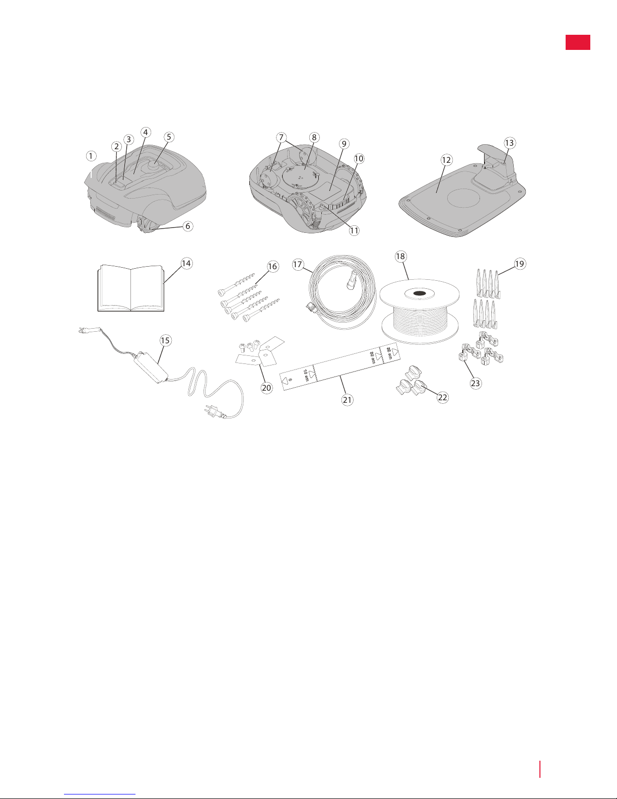
1 Removable cover
2 Stop button
3 Start button
4 LED indicators
5 Cutting height adjustment
6 Rear wheels
7 Front wheels
8 Blade disc
9 Battery cover
10 Carrying handle
11 Safety key
12 Charging station
13 LED for operation check
14 Operator manual and quick guide
15 Power supply*
16 Screws for securing charging station (x5)
17 Low voltage cable
18 Loop wire for boundary and guide wire
19 Wire pegs
20 Extra blades and screws (x3)
21 Ruler (break o carton top)
22 Splice and guide wire connectors (x3)
23 Loop wire connectors (x 3)
* The appearance of the power supply may dier depending on market.
Unbox the mower and installation materials. Make certain that all parts shown in Figure 1 are included and
undamaged. Contact your retailer if any items are missing or damaged.
Keep the Quick Guide in a safe place since it contains the unique pairing code for your mower.
Product Unboxing
Page 8

CRAMERTOOLS.COM
8
EN
Installation
Read the entire section before beginning installation. Installation aects mower capability.
Plan the installation carefully.
The following are the main tasks within the installation:
• Planning layout and preparation
• Installing and connecting the charging station
• Connecting the power supply
• Initial charging of the battery
• Installing the boundary wire
• Installing the guide wire
• Calibrating and initial start up
Planning Layout and Preparation
Ensure that the following conditions exist in the operating area where the mower will be used:
• The grass is shorter than 10 cm.
• There are no stones, loose pieces of wood, wire, live mains cables, and other foreign objects.
• The operating area is even and has no ditches, grooves, and steep slopes greater than 35%.
The following tools are required for installation, but not included:
• Hammer/rubber mallet to drive the pegs into the ground
• Combination pliers to cut the boundary wire
• Polygrip to press the couplers together
• Hex key, 6 mm for securing the charging station to ground
Page 9

CRAMERTOOLS.COM
9
EN
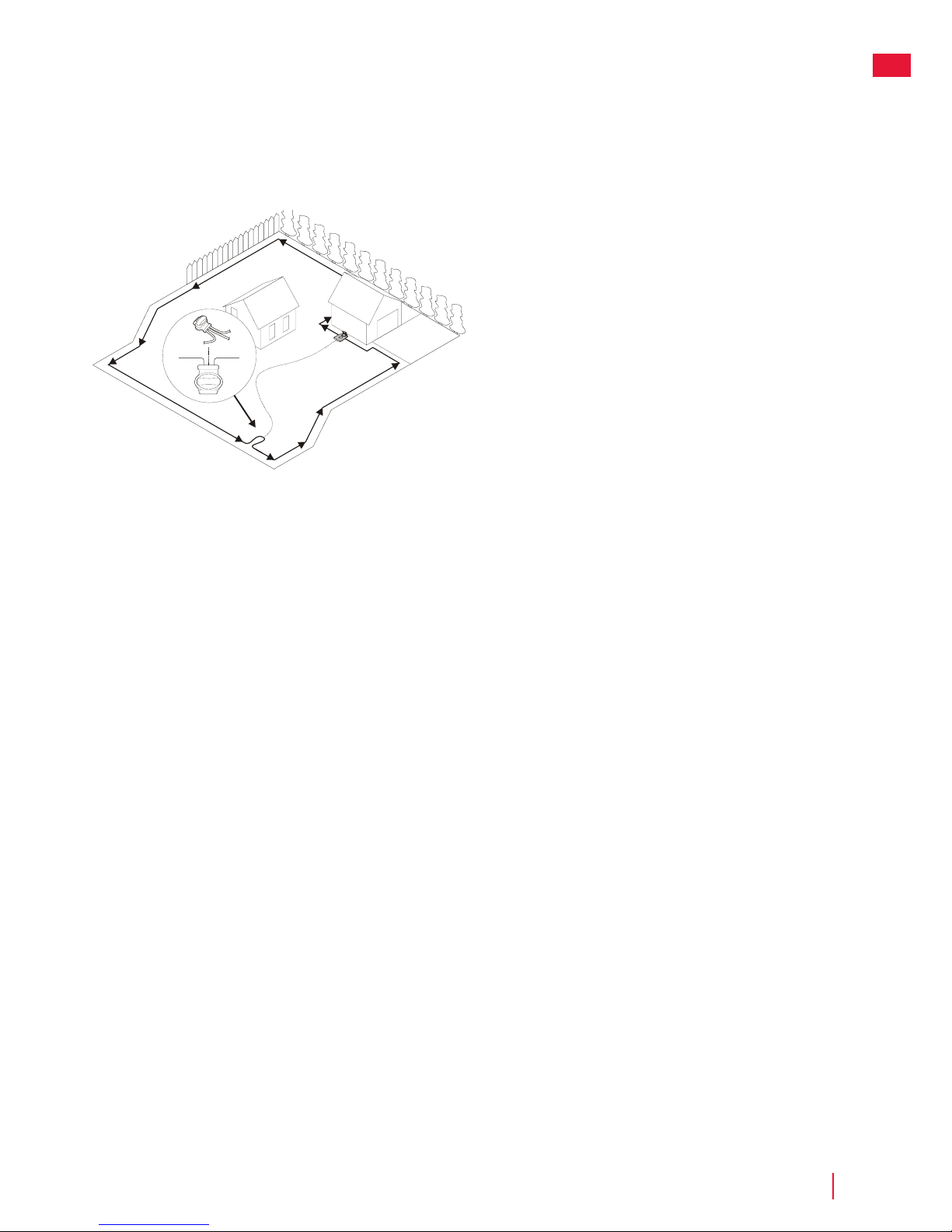
The majority of the charging station must be inside the operating area.
The following two options are shown in figure:
• Option 1 - Charging station is completely inside the operating area.
• Option 2 - Charging station partly outside the operating area.
Installation
Position for the charging station as follows:
• In a level spot out of direct sunlight
(The front end of the charging station must not be 5 cm higher or
lower than the back end.)
• Within reach of a wall socket
(The low voltage cable is 10 m long.)
• With at least 3 m in front of it and 1 m to each side
(Do not position in confined spaces in the operating area.)
Installing and Connecting the Charging Station
>1m
>1m
1m
35cm
>3m
10m
1.1.
2.
Page 10
CRAMERTOOLS.COM
10
EN
Connecting the Power Supply
Connect the power supply in a cool, dry environment; out of direct sunlight.
If the power supply is connected to an electrical socket outdoors, it must be approved for outdoor use.
The low voltage cable can cross the operating area if it is stapled down or buried.
CAUTION: Do not cut, splice, or alter the low voltage cable. Altering the low voltage cable will void the
product guarantee.
Installation
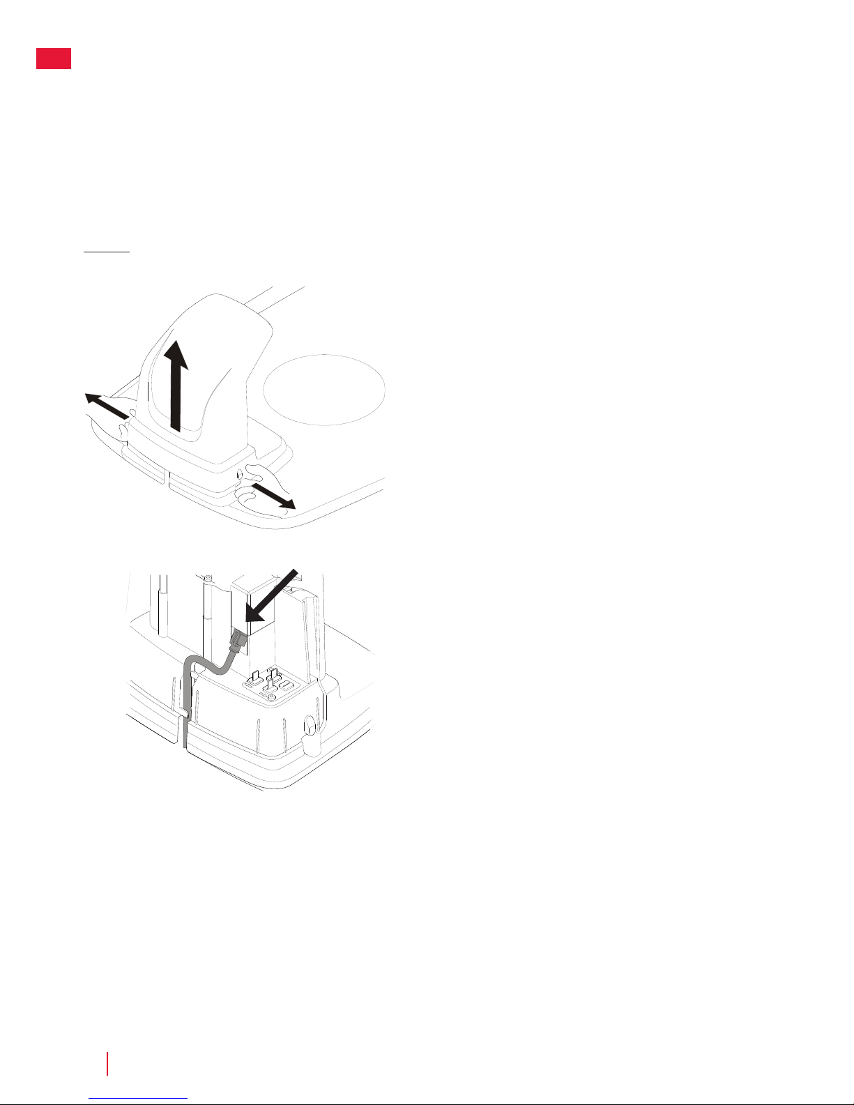
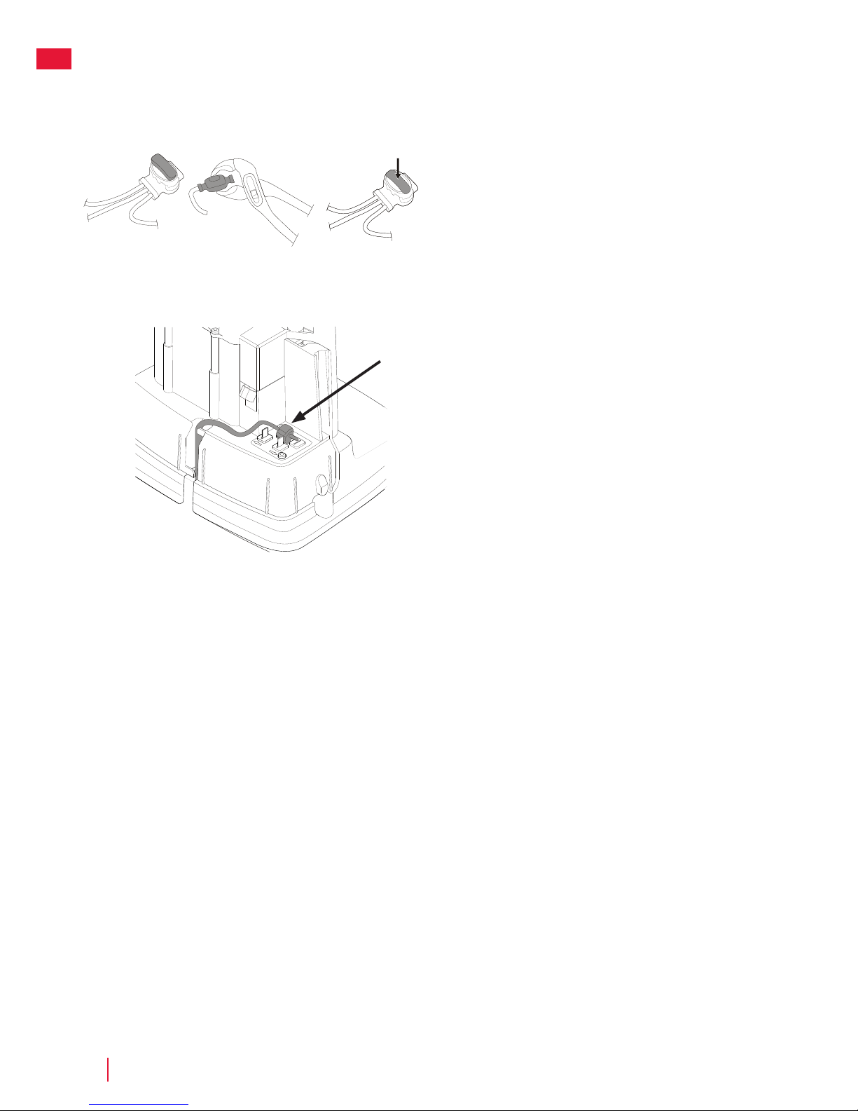
Connect the low voltage cable to the charging station.
Thread the low voltage cable behind the tabs to hold it in place in the
charging station.
Connect the power supply power cable to a 100-240 V wall socket.
Remove the protective cover on the charging station by pressing in the
tabs on each side of the base and lifting away the cover.
Page 11

CRAMERTOOLS.COM
11
EN
Installation
Initial Charging of the Battery
Insert the safety key into the underside of mower and turn to the Enable
position.
Place the mower into the charging station while the boundary
and guide wires are being laid.
The mower cannot be used before the installation is complete.
Page 12

CRAMERTOOLS.COM
12
EN
Installing the Boundary Wire
When installing the boundary wire there are a number of situations to consider as described in the table below.
Table 1. Handling Deviations and Obstacles in the Operating Area
Variation within Operating area Boundary Wire Planning
Fixed obstacles level with lawn that the mower can traverse (paving
stone paths or similar)
Lay the boundary wire under the paving stones or in the joint between
the paving stones.
Never run the mower over gravel, mulch, or similar material that can
damage the blades.
Fixed obstacles ± 1 cm high Lay the boundary wire 10 cm from the obstacle.
Fixed obstacles 1—5 cm high (small ditches, flower beds, or low
kerbstones)
Lay the boundary wire 30 cm from the obstacle.
Fixed obstacles 5 cm or higher (fences or walls) Lay the boundary wire 35 cm from the obstacle.
Fixed obstacles taller than 15 cm that can withstand a collision (trees
or shrubs)
No measures required; the mower will turn around when it collides
with this type of obstacle.
Fixed obstacles that slope slightly such as stones or large trees with
raised roots
Lay the boundary wire 30 cm from or remove obstacle.
Fixed obstacles that cannot withstand a collision Lay the boundary wire 30 cm from and around the obstacle and then
return it back along the same route.
Long and narrow passages and areas narrower than 1.5 m Install a guide wire.
Borders on a slope, road, precipice, or water Supplement the boundary wire with a physical barrier at least
15 cm high.
Slope up to 35% within operating area No measures required; the mower can operate up to a 35% as long as
the slope is not at the boundary of the operating area.
Slope less than 15% at operating area edge Lay boundary wire as normal.
Slope greater than 15% at operating area edge Do not lay boundary wire unless a fixed obstacle (fence or wall) exists
to prevent the mower from leaving the operating area.
When a part of the operating area outer edge slopes more than
15%; lay the boundary wire 20 cm in on the flat ground before the
beginning of the slope.
NOTE: Slope gradient is defined in percentage units (%). The slope as a percentage unit is calculated as the dierence in elevation in centimetres for
every metre. If, for example, the dierence in elevation is 10 cm, the slope gradient is 10%.
Installation
Page 13
CRAMERTOOLS.COM
13
EN
0cm
Installation
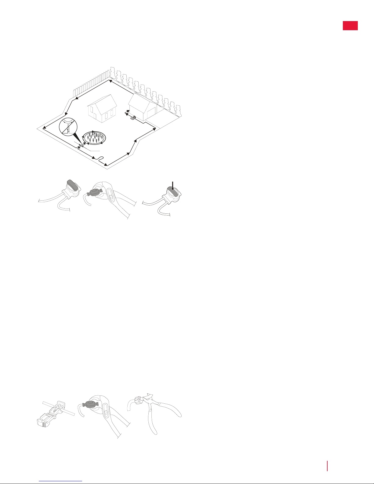
Temporarily secure the end of the loop wire to a peg or other object at
the charging station.
Lay out the loop wire in a counter-clockwise direction alone the planned
boundary of the operating area taking into consideration the rules in
Table 1 until you return to the charging station.
If you are going to install a guide wire, create an eyelet with about 20
cm of extra boundary wire at the point where the guide wire will later be
connected.
See Installing a Guide Wire on page 15 for more information.
If the boundary wire is too short, use provided splice and guide wire
connectors to splice additional boundary wire as follows:
1 Insert both ends of the boundary wire into the splice and guide
wire connector. Check that the wires are fully inserted into the
splice and guide wire connector so that the ends are visible
through the splice and guide wire connector.
2 Squeeze down the button on top of the splice and guide wire
connector fully using a polygrip until you hear a click.
Lay down the loop wire reel at the charging station.
Go back around the boundary of the operating area and secure the
boundary wire either using pegs or buried in the ground. Pegs are
recommended since this allows for adjustment during the first few
weeks of operation.
When securing the boundary wire with pegs:
• Cut the grass very low with a standard lawnmower or a trimmer
where the wire is to be laid.
• Lay the boundary wire on the ground and secure with pegs
close together.
• Push or hammer the pegs into the ground.
Do not push the pegs so far into the ground so that they strain the
boundary wire.
When burying the boundary wire:
• Bury the boundary wire 1—20 cm into the ground.
When the boundary wire is completely laid out and secured, install end
loop wire connectors as follows:
1 Open the loop wire connector and place the wire in the loop wire
connector grip.
2 Press the loop wire connectors together using a polygrip until you
hear a click.
Cut o any surplus boundary wire 1-2 cm above each connector.
Page 14

CRAMERTOOLS.COM
14
EN
Connect the boundary wire to the charging station as follows:
1 Remove the protective cover on the charging station and thread
the wire behind the tabs into the channel at the rear of the
charging station.
2 Press the connector onto the metal pins on the charging station
(marked with left and right arrows).
NOTE: Make sure the boundary wire to the right of the charging station
is connected to the arrow pointing right and the same for the left side.
Installation
Page 15
CRAMERTOOLS.COM
15
EN
Do not lay the guide wire closer than 30 cm from the boundary wire.
Do not lay the guide wire across the boundary wire.
Run the guide wire straight under the charging plate and then at least 2
m straight out from the front edge of the plate.
Leave as much space as possible to the left of the guide wire (as seen
when facing the charging station).
Use the same cable roll for both the boundary wire and the guide wire.
The guide wire, like the boundary wire, must be secured to the ground
with pegs or buried.
When installing the guide wire on a steep slope, lay the wire at an angle
to the slope so it is easier for the mower to follow the guide wire on the
slope.
Do not lay the guide wire at sharp angles or the mower will have
diculty following it.
Installing a Guide Wire
The mower uses the optional guide wire to find its way back to the
charging station, but also find hard-to reach areas of the operating area.
For example, the guide wire is laid between the charging station and a
remote part of the working area or through a narrow passage.
For narrow passages (less than 3 m) or to shorten search times, a guide
wire is recommended.
Plan the location of the guide wire before laying out the boundary wire.
Run the guide wire to the loop on the boundary wire where the guide
wire is to be connected.
Cut the boundary wire using the combination pliers.
Installation
Page 16
CRAMERTOOLS.COM
16
EN
Installation
Insert both ends of the boundary wire as well as the end of the guide
wire into the splice and guide wire connector. Check that the wires are
fully inserted into the splice and guide wire connector so that the ends
are visible through the splice and guide wire connector.
Squeeze down the button on top of the splice and guide wire connector
fully using a polygrip until you hear a click.
Secure the splice and the boundary and guide wires either using pegs
or by burying.
Connect the guide wire to the charging station as follows:
1 Remove the protective cover on the charging station and thread
the guide wire behind the tabs into the channel leading to the
terminals.
2 Connect the guide wire to the contact pin on the charging station
that is labelled G.
G
Page 17
CRAMERTOOLS.COM
17
EN
Pair the mower with Mobile App as instructed in Pairing Mobile App to
Mower on page 19.
Installation
Check the LED indicator on the charging station:
• LED indicator lights up continuously green, if the output voltage
of the power supply is available and the boundary wire is not
interrupted.
The LED indicator does not light up when the output voltage of the
power supply is not available.
If the indicator LED does not show a solid or green light, see Indicator
LEDs on the Charging Station on page 24 for troubleshooting.
Calibrating and Initial Start Up
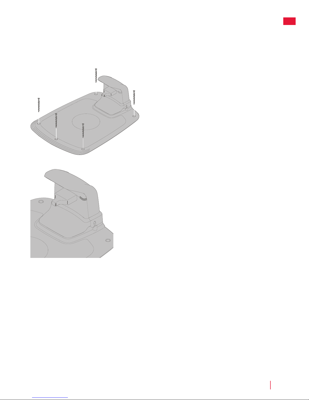
Secure the charging station to the ground using the five supplied fixing
screws using a 6 mm hex key.
NOTE: Do not make new holes in the charging station base plate. Only
the existing holes may be used to secure the base plate to the ground.
NOTE: Do not step or walk on the charging station base plate.
Page 18
CRAMERTOOLS.COM
18
EN
Operation
Starting and Stopping the Mower
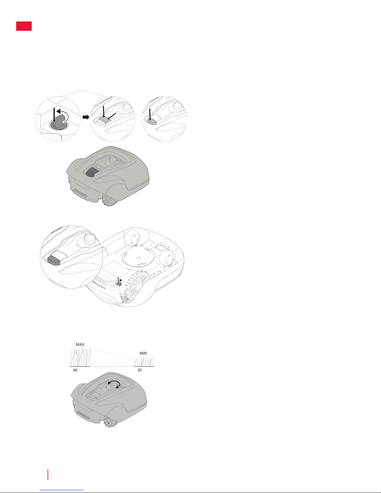
To start the mower:
1 Insert the safety key and rotate counter clockwise to position ”1”.
2 Slide the START button latch backwards.
3 Press down the START button.
To stop the mower:
Press the STOP button on the mower.
Switching O the Mower
Press the STOP button on the mower and remove the safety key.
WARNING! Always remove the safety key when performing
maintenance or if the mower must be moved.
Adjusting Cutting Height
For the first few weeks of mowing, set the cutting height to 60 mm to
avoid cutting the boundary wire and guide wire. Lower the setting one
step each week thereafter until the desired cutting height is reached.
Turn the cutting height adjustment knob to the required setting. The
selected setting is the marking on the body that aligns with the arrow on
the knob.
Turn clockwise to increase the cutting height.
Turn anti-clockwise to decrease the cutting height.
The cutting height for the mower can be adjusted between 20 mm and
60 mm.
MAX
60
20
MIN
Start Stop
a
b
a
b
Page 19
CRAMERTOOLS.COM
19
EN
Pairing Mobile App to Mower
Download Cramer GreenGuide from App Store/Google Play and follow the on-screen instructions for how to pair
the mower. Have the unique pairing code (found on the quick guide manual) and the mower at hand.
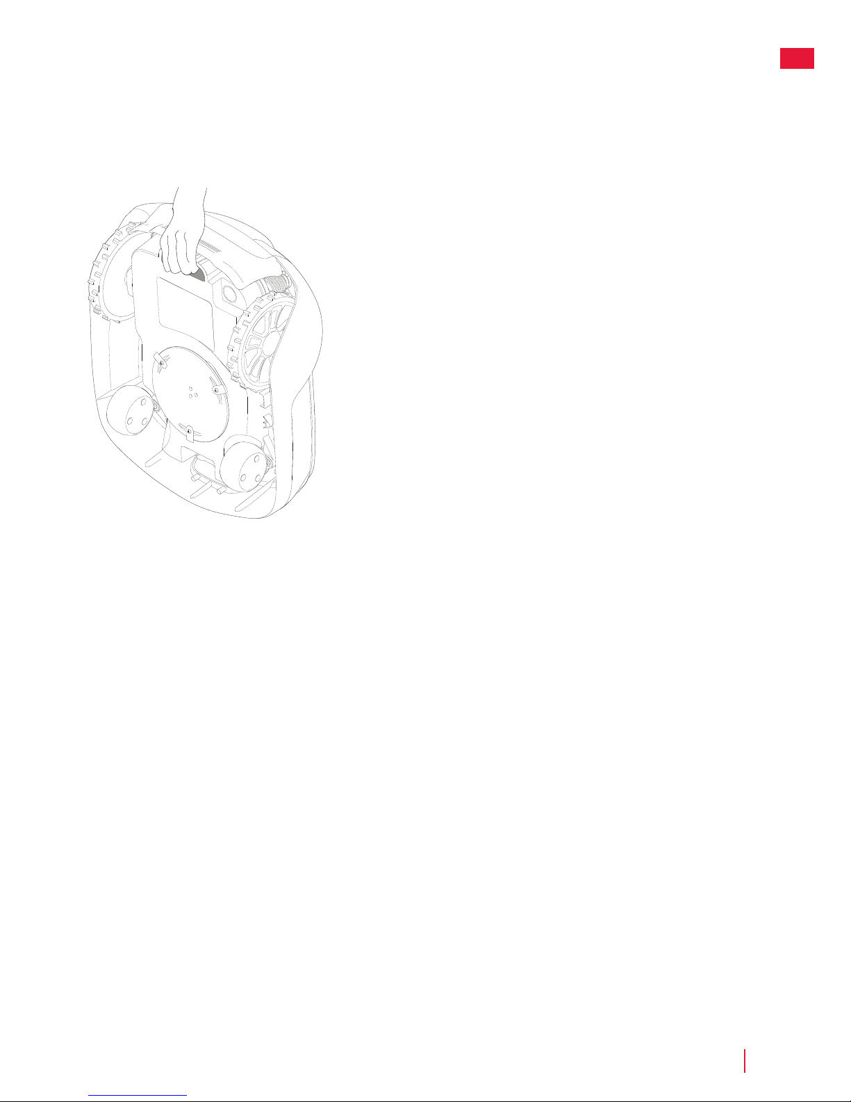
Lifting and Carrying the Mower
Press the STOP button and remove the safety key before lifting.
Always lift the mower using the carrying handle.
Operation
Page 20
CRAMERTOOLS.COM
20
EN
WARNING! Wear protective gloves when handling or working near the sharp blades.
WARNING! Before working on the mower itself, remove the safety key.
WARNING! Before working on the charging station or power supply, remove the plug from the
mains.
• Periodically visually inspect the mower and replace worn or damaged parts for safety.
• Inspect that the blades rotate freely
• Keep all nuts, bolts, and screws tight to be sure that the mower is in safe working condition.
• The normal operating life of the blades is 2 to 6 weeks when used at maximum area capacity and longer for
smaller areas.
CAUTION: Dull blades result in the grass being cut poorly; requiring more energy and shorter time between
battery loadings.
• Clean the mower regularly for best function.
Maintenance
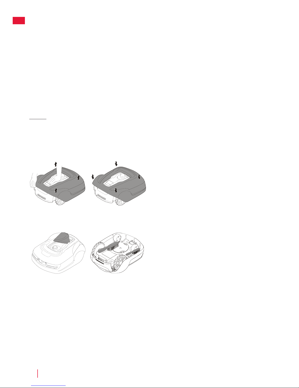
Removing the Body from Chassis
Hold down the mower with one hand and lift firmly at one of the corners
of the body and repeat for all four corners, until the body pops loose
from the chassis.
Replace the body by aligning the body onto the chassis and press down
firmly until you hear the click. Check that the body is firmly attached to
the chassis.
Cleaning
WARNING! Press the STOP button and remove the safety key
before cleaning.
Clean the exterior of the mower thoroughly using a soft brush, damp
cloth, and low pressure water hose, if necessary. Remove the body from
the chassis.
Turn the mower on its side and clean the blade area and wheels with a
sti brush or scraper to remove compacted grass clippings.
Page 21

CRAMERTOOLS.COM
21
EN
Maintenance
Maintaining the Battery
WARNING! In the event of electrolyte leakage, flush with
water/neutralizing agent and seek medical care if electrolyte
comes in contact with the eyes.
Only charge the battery in the original charging station. Incorrect use
may result in electric shock, overheating, or leakage of corrosive liquid
from the battery.
The battery is maintenance-free, but has a limited service life of 2 to 4
years depending on the length of the season and how many hours a day
the mower is used.
Replacing Blades
WARNING! Press the STOP button and remove the safety key
before replacing blades and wear protective gloves.
WARNING! Use only GLOBE’S blade: 333092355
CAUTION: Use only original replacement parts.
Replace all three blades and screws as a set at the same time.
Turn the mower upside down.
Loosen the screws using a straight slot or cross tip screwdriver.
Remove the blades and the screws.
Screw in the new blades using new screws.
Check that the blades pivot freely
cross tip screwdriver
Page 22
CRAMERTOOLS.COM
22
EN
Maintenance
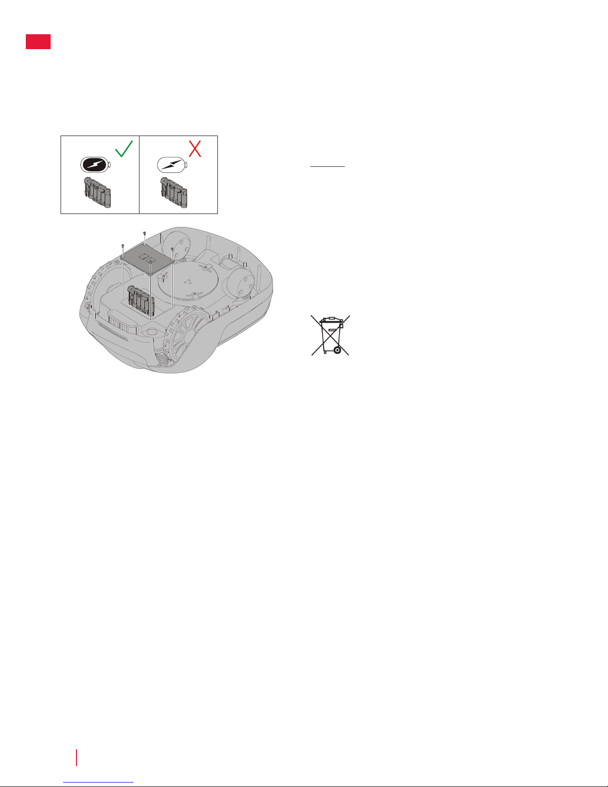
Replacing the Battery
WARNING! Press the STOP button and remove the safety key
before replacing batteries and wear protective gloves.
CAUTION: Use only original replacement parts.
Turn the mower upside down and remove the four Torx T20 screws and
remove the battery cover.
Disconnect the battery terminal connector.
Lift the battery straight out.
Insert the new battery in slot 1 (the rear slot).
Connect the battery terminal connector to the new battery.
Put the battery cover back into place and insert and tighten the four Torx
T20 screws.
Discard the old battery in accordance with local
environmental regulations.
Page 23

CRAMERTOOLS.COM
23
EN
Winter Storage Mower
Always clean the mower before winter storage.
Charge the battery fully before winter storage. If the battery is not fully charged it can be damaged and in certain
cases be rendered useless.
CAUTION: If the battery is not fully charged, it can be damaged and in certain cases be rendered useless.
Inspect the condition of wear items; that the blades are sharp and that blades and front wheels turn freely.
Correct any deficiencies.
Store the mower in a dry, frost-free environment standing on all four wheels.
Winter storage Charging Station
When possible, disconnect the boundary wire and guide wire from the charging station and store the charging
station and power supply indoors.
Leave the boundary wire and the guide wire in the ground, but protect the ends of the wires from dampness by
connecting them to an original coupler or putting them in a container with grease.
If it is not possible to store the charging station indoors, the charging station must remain connected to the
mains, the boundary wire, and the guide wires.
After Winter Storage
Inspect the mower and charging station contact and charging strips for corrosion, burning, or filth. If the charging
or contact strips require cleaning, clean using fine grade emery cloth.
Maintenance
Page 24
CRAMERTOOLS.COM
24
EN
Troubleshooting
Indicator LEDs on Charging Station
LED Status MeAning Action
5. Green On Boundary wire and Charging station OK No action required.
Blue Flashing Boundary wire broken or not connected Check and repair boundary wire.
Red Flashing Electronic fault in charging station or power supply Unit Please contact your dealer.
This section also presents some symptoms that can guide you if the mower does not work as expected.
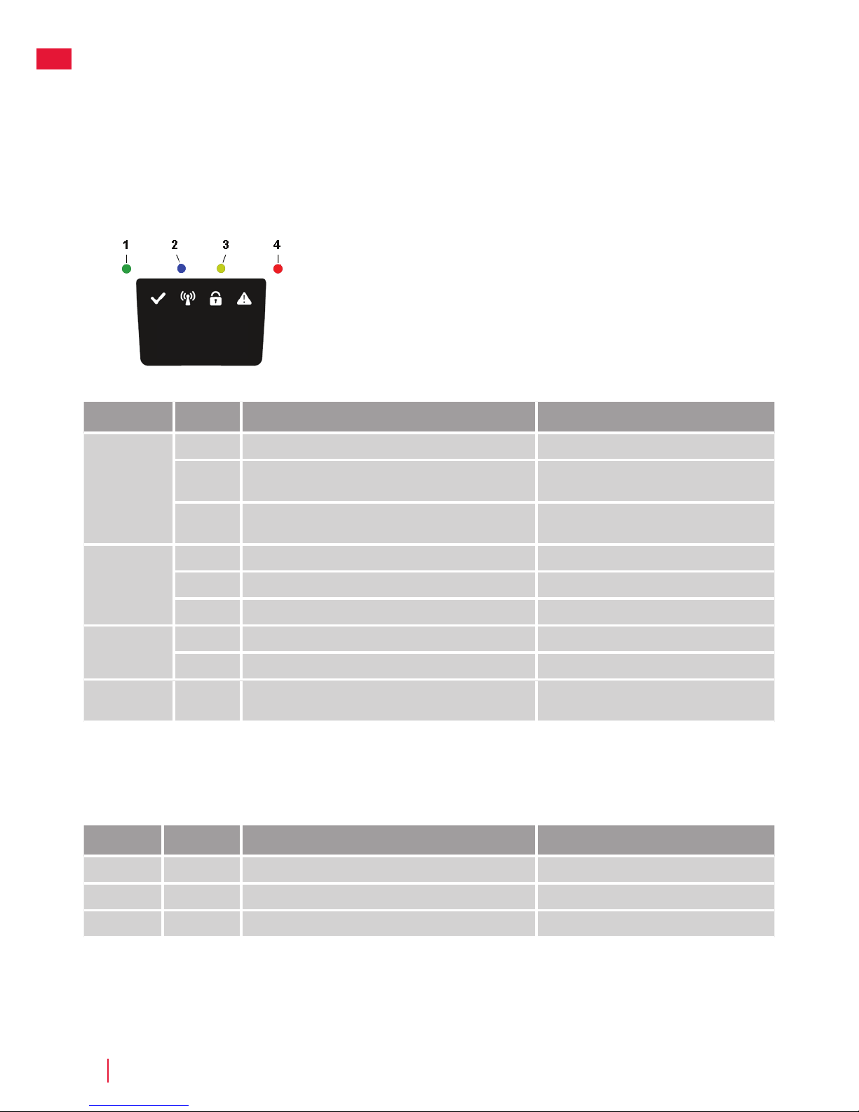
Indicator LEDs on Mower
LED Status MeAning Action
1. Operating
(Green)
Flashing Mower stopped with Stop button on mower Press Start on mower for operation
On Mower in operation mode (charging, parked in Charging
station, paused, mowing or searching)
O Safety key in in the Disabled position, mower in Error state
or mower waiting for PIN code.
2. Connectivity
(Blue)
Flashing Trying to connect to internet server
On Connected to internet server
O Mower not in ”Power on mode”
3. Security
(Yellow)
Flashing PIN code authorization required ... via Mobile App.
O No pin required No action required
4. Error
(Red)
Flashing Mower stopped with error Check the reason for the error and then restart
by pressing the Start button on the mower.
Page 25

CRAMERTOOLS.COM
25
EN
Symptoms
If your mower does not work as expected, follow the troubleshooting guide below.
Symptoms Cause Action
Mower has diculty
docking with charging
station
The charging station is on a slope. Place the charging station on a surface that is entirely
level. See Installing and connecting the Charging
Station on page 9.
The boundary wire is not laid correctly in relation to
the charging station.
Check that the charging station and boundary wire
has been correctly installed. See Installing and
connecting the Charging Station on page 9.
Uneven mowing results The mower works too few hours per day. Increase the operation time. See the Scheduling
function in the Mobile App.
The shape of the working area requires manual
settings to be made for the mower to find its way to all
remote areas.
Adjust lawn coverage to steer the mower to one
or more remote areas. See Settings function in the
Mobile App.
The shape of the working area requires manual
settings to be made for the mower to find its way to all
remote areas.
Try limiting the operating area or extending the
operation time. See the Scheduling function in the
Mobile App.
The blades are dull. Replace all the blades and screws so that the rotating
parts are balanced. See Replaceing blades on page
21.
Grass collects on the blade disc or around the motor
shaft.
Check that the blade disc rotates easily. If not, remove
grass and foreign objects. See Maintenance on page
20.
The mower mows for
shorter periods than usual
between charges
Grass or other foreign object are blocking the blade
disc.
Remove grass and foreign objects. See Maintenance
on page 20.
The battery is worn out. Replace the battery. See Replacing the Battery on
page 22.
Mowing and charging times
shorter than usual
The battery is worn out. Replace the battery. See Replacing the Battery on
page 22.
Breaks in Boundary Wire and Guide Wire
Breaks in the boundary wire and guide wire (if installed) are usually the result of unintentional physical damage.
Inspect the entire boundary wire from the charging station and back.
Inspect the guide wire (if installed) from the charging station to the splice into the boundary wire.
Inspect that all the couplings have been properly squeezed to make connections.
Troubleshooting
Page 26

CRAMERTOOLS.COM
26
EN
Technical Data
Optimow 10 Optimow 15
Dimensions:
Height 26 cm 26 cm
Length 62 cm 62 cm
Width 50 cm 50 cm
Weight 11 kg 11 kg
Electrical system:
Battery, Special Lithium-Ion battery 24 V / 2.0 Ah, Part No. 211022355 24 V / 2.0 Ah, Part No. 211022355
Power supply 100-240 V/32 V DC 100-240 V/32 V DC
Low voltage cable length 10 m 10 m
Mean energy consumption at maximum use 8 kWh/month for a working area of 1,000 m
2
10 kWh/month for a working area of 1,500 m
2
Charge current 1.3 A DC 1.3 A DC
Average charging time 140 minutes 70 minutes
Average cutting time 70 minutes 70 minutes
Noise emissions: *)
Measured sound power noise level **) 58 dB (A) 58 dB (A)
Guaranteed sound power noise level 60 dB (A) 60 dB (A)
Sound pressure noise level ***) 47 dB (A) 47 dB (A)
Mowing:
Cutting system Three pivoted cutting blades Three pivoted cutting blades
Average power consumption during cutting 25 W ± 20% 25 W ± 20%
Cutting height 2-6 cm 2-6 cm
Cutting width 22 cm 22 cm
Narrowest possible passage 60 cm 60 cm
Maximum angle for cutting area 35% 35%
Maximum angle for boundary wire 15% 15%
Maximum length boundary wire 800 m 800 m
Maximum working capacity 1,000 m
2
1,500 m
2
Recommended area capacity 0 - 700 m
2
500 - 1,200 m
2
IP classification:
Mower IPX5 IPX5
Charging station IPX2 IPX2
Power supply IP67 IP67
*) Noise emissions in the environment measured as sound power (LWA) in conformity with EC directive 2000/14/EC. The guaranteed sound power
level includes variation in production as well as variation from the test code with 1-3 dB(A).
The noise emission declarations conforms to EN 50636-2-107:2015
**) uncertainties KWA, 2 dB (A)
***) uncertainties KPA, 2-4 dB (A)
Page 27
CRAMERTOOLS.COM
27
EN
Environmental Protection
According to the European law 2012/19/EU, electrical and electronic equipment that is no longer
usable, and according to the European law 2006/66/EC, defective or used battery packs/
batteries, must be collected separately and disposed of in an environmentally correct manner.
The symbol on the mower or its packaging indicates that this product cannot be treated as
domestic waste. It should instead be left at a suitable recycling centre to recycle its electronic
components and batteries.
The batteries are enclosed in the chassis under the mower. See Replacing the Battery on page
22 for battery removal.
By ensuring that this product is taken care of correctly, you can help to counteract the potential
negative impact on the environment and people that can otherwise result through the incorrect
waste management of this product.
For more detailed information about recycling this product, contact your municipality, your
domestic waste service or the shop from where you purchased the product.
Separate collection of used machine and packaging let you recycle materials and use them
again. Use of the recycled materials helps prevent environmental pollution and decreases the
requirements for raw materials.
At the end of their useful life, discard batteries with a precaution for our environment. The battery
contains material that is dangerous to you and the environment. You must remove and discard
these materials separately at a equipment that accepts lithium-ion batteries.
Page 28

CRAMERTOOLS.COM
28
EN
Warranty Terms
GLOBGRO AB, Globe Group Europe guarantees this product’s functionality for a period of two years (from date of
purchase). The guarantee covers serious faults relating to materials or manufacturing faults. Within the guarantee
period, we will replace the product or repair it at no charge if the following terms are met:
• The mower and the charging station may only be used in compliance with the instructions in this operator
manual.
• Users or non-authorized third parties must not attempt to repair the product.
Examples of faults which are not included in the guarantee:
• Damage caused by lightning.
• Damage caused by improper battery storage or battery handling.
• Damage caused by using a battery that is not a original battery.
• Damage caused by not using original spare parts and accessories, such as blades and installation material.
• Damage to the loop wire.
The blades are seen as disposable and are not covered by the guarantee.
If a fault occurs with your mower, please contact the dealer for further instructions. Have your receipt and product
serial number to hand for quicker assistance.
Page 29

CRAMERTOOLS.COM
29
EN
(Only applicable to European versions)
Manufacturer: GLOBGRO AB, Globe Group Europe
Address: Propellergatan 1, 21115 Malmö, Sweden
Name and address of the person authorized to compile the
technical file:
Peter Söderström
Propellergatan 1, 21115 Malmö, Sweden
Herewith we declare that the product:
Category: Robotic Lawnmower
Model: RM1000/RM1500
Serial number: See product rating label.
Serial No See product rating label.
• Is in conformity with the relevant provisions of the Machinery
Directive (2006/42/EC)
• Particular requirements for robotic battery powered electrical
lawnmowers EN 50636-2-107: 2015 / A1:2018
• Is in conformity with the provisions of the following other directives:
2014/30/EU EN 55014-1:2017 EN 55014-2:2015
Noise Emission Directive (2000/14/EC amended by 2005/88/EC)
2014/53/EU, RF EN 303413, EN 301489-1/-19, EN303447, EN301 489-1/3, EN 301489-1/-52, EN 301511, EN 62479
And furthermore, we declare that:
• The following (parts/classes of) European harmonized standards
have been used:
EN 60335-1:2012+A11+A13:2017, EN 50636-2-107:2015+A1:2018, EN
60335-2-29:2004+A2:2010, EN 62233:2008, EN ISO 3744:2005,
EN 55014-1:2017, EN 55014-2:2015, EN 61000-3-2:2014, EN 61000-33:2013, EN 300 328 V2.1.1, EN 301 489-1 V2.1.1, EN 301 489-17 V3.1.1, EN
62311:2008, EN 61558-1:2005+A1:2009, EN 61558-2-16:2009+A1:2013
Measured sound power level 58 dB(A)
Guaranteed sound power level 60 dB(A)
Conformity assessment method to: Annex V/Directive 2000/14/EC
EC type examination certificate number: 13SHN0023-01
Ted Qu Haichao
Quality Director
Changzhou, 1 December 2018
CE Declaration of Conformity
Page 30

CRAMERTOOLS.COM
2
DE
Die Materialien, technischen Daten und Abbildungen in diesem Handbuch dienen nur der
Orientierung und sind nicht verbindlich. Der Hersteller behält sich das Recht vor, ohne vorherige
Ankündigung Änderungen an den technischen Eigenschaften und allen Merkmalen des Betriebs, der
Materialien, der technischen Daten oder der Abbildungen vorzunehmen.
Auf den folgenden Seiten finden Sie wichtige Sicherheitsund Betriebsanweisungen.
Lesen und überprüfen Sie sorgfältig alle
Sicherheitshinweise, Warnungen und
Vorsichtsmaßnahmen in diesem Handbuch.
Das Nichtbeachten dieser Anweisungen, Sicherheits- und
Warnhinweise kann zu schweren Verletzungen oder zum
Tod von Personen und Haustieren oder zu Beschädigung
von persönlichem Eigentum führen.
Page 31

Inhalt
Produktsicherheit ..................................................................................................... 4
Lesen des bedienungshandbuchs ............................................................... 4
Betriebssicherheit .............................................................................................6
Auspacken des produkts ....................................................................................... 7
Montage ......................................................................................................................8
Lageplan und Vorbereitung ...........................................................................8
Installation und Anschluss der Ladestation ............................................... 9
Positionieren Sie die Ladestation wie folgt: ...............................................9
Anschluss des netzteils ................................................................................. 10
Erstladung des akkus ......................................................................................11
Installation des begrenzungsdrahts ...........................................................12
Installation eines führungsdrahts ................................................................15
Kalibrierung und erstinbetriebnahme.........................................................17
Bedienung .................................................................................................................18
Starten und stoppen des mähers ................................................................18
Ausschalten des mähers................................................................................18
Einstellen der schnitthöhe .............................................................................18
Anheben und tragen des mähers ...............................................................19
Koppeln der mobilen app mit dem mäher ................................................19
Wartung und Instandhaltung .............................................................................. 20
Entfernen der karosserie vom fahrgestell ............................................... 20
Reinigung ......................................................................................................... 20
Austausch der messer ....................................................................................21
Wartung des akkus ..........................................................................................21
Auswechseln des akkus ...............................................................................22
Lagerung des mähers im winter .................................................................23
Lagerung der ladestation im winter ...........................................................23
Fehlerbehebung .....................................................................................................24
Anzeige-leds am mäher ................................................................................24
Problem .............................................................................................................25
Brüche im begrenzungsdraht und
Führungsdraht .................................................................................................25
Technische Daten ...................................................................................................26
Schutz der Umwelt .................................................................................................27
Garantiebedingungen ...........................................................................................28
EG-Konformitätserklärung ....................................................................................29
CRAMERTOOLS.COM
3
DE
Page 32

CRAMERTOOLS.COM
4
DE
Erläuterung der Symbole am Mäher
Dies ist ein gefährliches Elektrowerkzeug. Seien Sie bei der Bedienung vorsichtig und
befolgen Sie alle Sicherheitshinweise und Warnungen.
Lesen Sie das Bedienungshandbuch sorgfältig durch, bevor Sie den Mäher in Betrieb
nehmen.
Entfernen Sie den Sicherheitsschlüssel, bevor Sie am Mäher arbeiten oder ihn anheben.
Es besteht Gefahr durch geworfene Gegenstände während des Betriebs.
Halten Sie beim Bedienen einen sicheren Abstand zum Mäher und halten Sie Personen,
insbesondere Kinder, Haustiere und umstehende Personen von dem Bereich fern, in
dem der Mäher betrieben wird.
Steigen Sie nicht auf den Mäher.
Gerät der Klasse III
Lesen des Bedienungshandbuchs
Ergänzend zu diesem Bedienungshandbuch finden Sie weitere Informationen auf der
Website: www.cramertools.com
Die folgenden Symbole sind wichtig zum Lesen und Verstehen der Betriebsanleitung.
Schutzhandschuhe tragen
Das folgende System wird im Bedienungshandbuch verwendet, um das Verständnis zu
erleichtern:
• WARNUNG! Warnhinweise weisen Benutzer und Verbraucher auf Vorhandensein und Art von Gefahren
hin, damit sie durch angemessenes Verhalten bei der Verwendung des Produkts Verletzungen
vermeiden können.
• VORSICHT: Warnhinweise weisen Benutzer und Verbraucher auf Vorhandensein und Art der Produktrisiken
hin, so dass sie durch angemessenes Verhalten während der Verwendung des Produkts eine
Beschädigung des Produkts vermeiden können.
• HINWEIS: Hinweise informieren Benutzer und Verbraucher über zusätzliche Informationen zur
Produktnutzung.
• Fett kursiv gedruckter Text verweist auf einen weiteren Abschnitt im Bedienungshandbuch.
• Fett gedruckter Text bezieht sich auf die Einstellungen am Mäher.
Produktsicherheit
Page 33

CRAMERTOOLS.COM
5
DE
Produktsicherheit
WICHTIG
VOR GEBRAUCH AUFMERKSAM LESEN! ZUR SPÄTEREN VERWENDUNG AUFBEWAHREN!
Einführung
WARNUNG! Automatischer Rasenmäher! Von der Maschine fernhalten! Kinder beaufsichtigen!
• Lesen Sie die Anleitung aufmerksam durch. Machen Sie sich mit den Bedienelementen und dem
ordnungsgemäßen Gebrauch der Maschine vertraut.
• Lassen Sie niemals Personen, die mit diesen Anweisungen nicht vertraut sind, oder Kinder die Maschine
benutzen. Lokale Vorschriften können das Alter für den Betrieb der Maschine einschränken.
• Der Betreiber oder Benutzer ist für Unfälle oder Gefahren für andere Personen oder deren Eigentum
verantwortlich.
Vorbereitung
• Vergewissern Sie sich, dass die korrekte Installation des automatischen Begrenzungssystems gemäß den
Anweisungen durchgeführt wurde.
• Überprüfen Sie regelmäßig den Einsatzbereich der Maschine und entfernen Sie alle Steine, Stöcke, Kabel,
Knochen und andere Fremdkörper.
• Regelmäßig visuell überprüfen, um sicherzustellen, dass die Messer, Messerschrauben und die
Schneidevorrichtung nicht abgenutzt oder beschädigt sind. Ersetzen Sie verschlissene oder beschädigte
Messer und Schrauben in Sets, um das Gleichgewicht zu erhalten.
• Bei Mehrspindelmaschinen ist darauf zu achten, dass sich durch das Drehen eines Messers andere Messer
ebenfalls drehen können.
Allgemeines
• Betreiben Sie die Maschine niemals mit defekten Schutzabdeckungen oder ohne Sicherheitsvorrichtungen,
wie z.B. Abweiser und/oder Grasfangeinrichtungen.
• Hände oder Füße nicht in die Nähe von oder unter rotierende Teile bringen. Halten Sie sich immer von der
Entleerungsönung fern.
• Nehmen Sie niemals eine Maschine in die Hand, während der Motor läuft.
• Entfernen (oder Bedienen) Sie die Sperrvorrichtung von der Maschine
- vor dem Beseitigen einer Verstopfung;
- vor dem Prüfen, Reinigen oder Arbeiten an der Maschine.
• Lassen Sie die Maschine nicht unbeaufsichtigt arbeiten, wenn Sie wissen, dass sich Haustiere, Kinder oder
Personen in der Nähe befinden.
Wartung und Lagerung
• Alle Muttern, Bolzen und Schrauben müssen stets fest angezogen sein, um sicherzustellen, dass sich die
Maschine in einem sicheren Betriebszustand befindet.
• Überprüfen Sie den Grasfangvorrichtung regelmäßig auf Verschleiß oder Beschädigung.
• Ersetzen Sie verschlissene oder beschädigte Teile aus Sicherheitsgründen.
• Achten Sie darauf, dass nur Ersatzschneidmittel des richtigen Typs verwendet werden.
• Stellen Sie sicher, dass die Akkus mit dem vom Hersteller empfohlenen Ladegerät geladen werden.
Unsachgemäße Verwendung kann zu Stromschlag, Überhitzung oder Austreten von korrosiver Flüssigkeit
aus der Batterie führen.
• Bei Austreten von Elektrolyt, mit Wasser/Neutralisierungsmittel spülen. Suchen Sie einen Arzt auf, wenn die
Augen etc. mit Elektrolyt in Berührung gekommen sind.
• Die Wartung der Maschine sollte gemäß den Anweisungen des Herstellers erfolgen.
Page 34

CRAMERTOOLS.COM
6
DE
Betriebssicherheit
Dieses Bedienungshandbuch enthält alle grundlegenden Informationen über den sicheren
Betrieb und die Wartung des Mähers.
Produktsicherheit
Lesen Sie vor der Inbetriebnahme des Mähers alle Sicherheitshinweise und Anweisungen in
diesem Bedienungshandbuch sorgfältig durch. Bewahren Sie dieses Bedienungshandbuch zum
späteren Nachschlagen auf. Befolgen Sie die Anweisungen des Herstellers bezüglich Installation,
Betrieb, Wartung und Reparatur.
Dieser Mäher wurde entwickelt, um Gras in oenen und ebenen Bereichen zu mähen. Verwenden
Sie nur die vom Hersteller empfohlenen Geräte. Alle anderen Nutzungsarten sind unsachgemäß.
Dieser Mäher entspricht den CE-Sicherheitsnormen und -richtlinien bezüglich elektromagnetischer
Verträglichkeit, Maschinen und Niederspannung.
Der Mäher ist nicht zur Verwendung durch Personen (einschließlich Kinder) vorgesehen, deren
physische, sensorische oder geistige Fähigkeiten eingeschränkt sind, denen die Erfahrung und
das Wissen fehlt, sofern sie nicht bei der Verwendung der Maschine durch eine für ihre Sicherheit
verantwortliche Person überwacht werden oder eingewiesen wurden.
Kinder sollten beaufsichtigt werden, um sicherzustellen, dass sie nicht mit der Vorrichtung spielen.
Der Mäher darf nur von Personen betrieben, gewartet und repariert werden, die seine
Besonderheiten und Sicherheitsvorschriften kennen.
Starten Sie den Mäher gemäß den Anweisungen. Wenn sich der Sicherheitsschlüssel in der
aktivierten Position befindet, halten Sie Ihre Hände und Füße von den rotierenden Messern fern.
Legen Sie niemals Ihre Hände und Füße unter den Mäher.
Ändern Sie nicht die ursprüngliche Konstruktion des Mähers. Alle diesbezüglichen Veränderungen
führen zum Erlöschen der Garantie.
Schalten Sie den Mäher mit der STOP-Taste am Mäher aus, wenn sich Personen, insbesondere
Kinder oder Haustiere im Schneidebereich befinden. Es wird empfohlen, den Mäher so zu
programmieren, dass der Bereich während des Betriebs frei von Personen oder Haustieren ist.
Entfernen Sie Gegenstände aus dem Betriebsbereich wie Äste, Spielzeug, Steine, Werkzeuge, die
die Messer beschädigen können. Der Mäher kann an Gegenständen im Betriebsbereich hängen
bleiben und somit nicht weitermähen, bevor die Gegenstände entfernt werden.
Heben Sie den Mäher niemals an und tragen Sie ihn nicht während der Sicherheitsschlüssel noch
eingesteckt ist.
Schalten Sie den Mäher immer mit der STOP-Taste aus, wenn der Mäher nicht in Gebrauch ist. Der
Mäher kann nur gestartet werden, wenn der Sicherheitsschlüssel eingesteckt und die START-Taste
gedrückt ist.
Der eingebaute Alarm ist sehr laut. Seien Sie vorsichtig, besonders wenn der Mäher in
Innenräumen eingesetzt wird.
Verwenden Sie den Mäher nicht mit einer defekten Messerscheibe oder Karosserie.
Lassen Sie ihn nicht von Personen benutzen, die nicht wissen, wie der Mäher funktioniert und sich
verhält.
Stellen Sie nichts auf den Mäher oder seine Ladestation.
Tragen Sie bei Arbeiten mit den Messern des Mähers immer Schutzhandschuhe.
Page 35

CRAMERTOOLS.COM
7
DE
1
2
3
4
5
7
8
9
10
11
12
13
17
19
181521
20
23
22
16
14
6
1 Abnehmbare Abdeckung
2 Stopp-Taste
3 Start-Taste
4 LED-Anzeigen
5 Schnitthöhenverstellung
6 Hinterräder
7 Vorderräder
8 Messerscheibe
9 Batterieabdeckung
10 Tragegri
11 Sicherheitsschlüssel
12 Ladestation
13 LED zur Funktionsprüfung
14 Bedienungshandbuch und Kurzanleitung
15 Netzteil*
16 Schrauben zur Befestigung der Ladestation (5 Stk.)
17 Niederspannungskabel
18 Schleifendraht für Begrenzungs- und Führungsdraht
19 Drahthaken
20 Zusätzliche Messer und Schrauben (3 Stk.)
21 Lineal (Kartonverschluss abbrechen)
22 Spleiß- und Führungsdrahtverbinder (3 Stk.)
23 Schleifendrahtverbinder (3 Stk.)
* Das Aussehen des Netzteils kann je nach Land unterschiedlich sein.
Packen Sie den Mäher und die Installationsmaterialien aus. Stellen Sie sicher, dass alle in Abbildung 1
dargestellten Teile enthalten und unbeschädigt sind. Wenden Sie sich an Ihren Händler, wenn Teile fehlen oder
beschädigt sind.
Bewahren Sie die Kurzanleitung an einem sicheren Ort auf, da sie den eindeutigen Kopplungscode für Ihren
Mäher enthält.
Auspacken des Produkts
Page 36

CRAMERTOOLS.COM
8
DE
Montage
Lesen Sie den gesamten Abschnitt, bevor Sie mit der Installation beginnen. Die Installation beeinflusst die
Leistungsfähigkeit des Mähers.
Planen Sie die Installation sorgfältig.
Nachfolgend sind die wichtigsten Schritte für die Installation aufgeführt:
• Lageplan und Vorbereitung
• Installation und Anschluss der Ladestation
• Anschluss der Netzteils
• Erstladung des Akkus
• Installation des Begrenzungsdrahts
• Installation des Führungsdrahts
• Kalibrierung und Erstinbetriebnahme
Lageplan und Vorbereitung
Stellen Sie sicher, dass die folgenden Bedingungen im Betriebsbereich, in dem der Mäher eingesetzt wird,
gegeben sind:
• Das Gras ist kürzer als 10cm.
• Es dürfen keine Steine, lose Holzstücke, Drähte, stromführende Netzkabel und andere Fremdkörper
vorhanden sein.
• Das Betriebsgelände ist eben und weist keine Gräben, Vertiefungen und steilen Hänge von mehr als 35%
auf.
Die folgenden Werkzeuge werden für die Installation benötigt, sind aber nicht im Lieferumfang enthalten:
• Hammer/Gummi-Schlägel zum Eintreiben der Haken in den Boden
• Kombizange zum Schneiden des Begrenzungsdrahts
• Verstellbare Zange zum Zusammendrücken der Kupplungen
• Innensechskant-Schlüssel, 6mm zur Befestigung der Ladestation am Boden
Page 37

CRAMERTOOLS.COM
9
DE
Die Ladestation muss sich größtenteils innerhalb des Betriebsbereichs
befinden.
Die folgenden beiden Optionen sind in der Abbildung dargestellt:
• Option 1 - Die Ladestation befindet sich vollständig im
Betriebsbereich.
• Option 2 - Die Ladestation befindet sich partiell außerhalb des
Betriebsbereichs.
Montage
Positionieren Sie die Ladestation wie folgt:
• An einem ebenen Ort ohne direkte Sonneneinstrahlung
(Das vordere Ende der Ladestation darf nicht 5cm höher oder
niedriger sein als das hintere Ende.)
• In Reichweite einer Steckdose
(Das Niederspannungskabel ist 10m lang.)
• Mit mindestens 3m freiem Platz zur Vorderseite und je 1m zu den
Seiten
(Nicht in engen Umgebungen im Betriebsbereich positionieren.)
Installation und Anschluss der Ladestation
>1m
>1m
1m
35cm
>3m
10m
1.1.
2.
Page 38

CRAMERTOOLS.COM
10
DE
Anschluss des Netzteils
Schließen Sie das Netzteil in einer kühlen, trockenen Umgebung an, außerhalb der direkten Sonneneinstrahlung.
Wird das Netzteil an eine Steckdose im Freien angeschlossen, muss sie für den Außeneinsatz zugelassen sein.
Das Niederspannungskabel kann den Betriebsbereich durchqueren, wenn es am Boden entlang festgeheftet
oder eingegraben wird.
VORSICHT: Das Niederspannungskabel darf nicht geschnitten, gespleißt oder modifiziert werden.
Veränderungen am Niederspannungskabel führen zum Erlöschen der Produktgarantie.
Montage
Schließen Sie das Niederspannungskabel an die Ladestation an.
Führen Sie das Niederspannungskabel hinter die Laschen, damit es in
der Ladestation optimal liegt.
Schließen Sie das Stromkabel an eine 100-240V Steckdose an.
Entfernen Sie die Schutzabdeckung der Ladestation, indem Sie die
Laschen auf jeder Seite der Basis eindrücken und die Abdeckung
abnehmen.
Page 39

CRAMERTOOLS.COM
11
DE
Montage
Erstladung des Akkus
Stecken Sie den Sicherheitsschlüssel in die Unterseite des Mähers und
drehen Sie ihn in die aktivierte Position.
Stellen Sie den Mäher in die Ladestation, während die
Begrenzungs- und Führungsdrähte verlegt werden.
Der Mäher kann vor Abschluss der Installation nicht verwendet
werden.
Page 40

CRAMERTOOLS.COM
12
DE
Installation des Begrenzungsdrahts
Bei der Installation des Begrenzungsdrahts gibt es eine Reihe von Situationen, die wie in der folgenden Tabelle beschrieben zu berücksichtigen sind.
Tabelle 1. Umgang mit Abweichungen und Hindernissen im Betriebsbereich
ABWEICHUNG INNERHALB DES BETRIEBSBEREICHS VERLEGUNG DES BEGRENZUNGSDRAHTS
Feststehende, mit der Rasenfläche ebenerdig abschließende
Hindernisse, die der Mäher überfahren kann (Pflastersteinpfade o.ä.)
Verlegen Sie den Begrenzungsdraht unter den Pflastersteinen oder in
den Fugen zwischen den Pflastersteinen.
Fahren Sie den Mäher niemals über Kies, Mulch oder ähnliches
Material, das die Messer beschädigen kann.
Feststehende Hindernisse ±1cm hoch Verlegen Sie den Begrenzungsdraht 10 cm vom Hindernis entfernt.
Feststehende Hindernisse von 1-5cm Höhe (kleine Gräben,
Blumenbeete oder niedrige Randsteine)
Verlegen Sie den Begrenzungsdraht 30 cm vom Hindernis entfernt.
Feststehende Hindernisse 5cm oder höher (Zäune oder Wände) Verlegen Sie den Begrenzungsdraht 35cm vom Hindernis entfernt.
Feststehende Hindernisse, die höher als 15cm sind und einer Kollision
standhalten können (Bäume oder Sträucher)
Keine Maßnahmen erforderlich; der Mäher dreht um, wenn er mit
einem solchen Hindernis kollidiert.
Feststehende Hindernisse mit leichter Steigung wie Steine oder große
Bäume mit erhöhten Wurzeln
Verlegen Sie den Begrenzungsdraht 30cm vom Hindernis entfernt
oder entfernen Sie das Hindernis.
Feststehende Hindernisse, die einer Kollision nicht standhalten
können
Verlegen Sie den Begrenzungsdraht in einem Umkreis von 30cm um
das Hindernis und bringen Sie es dann auf dem gleichen Weg wieder
zurück.
Lange und schmale Durchgänge und Bereiche, die enger als 1,5m
sind
Installieren Sie einen Führungsdraht.
Begrenzungen an Steigungen, Straßen, Steilhängen oder Gewässern Ergänzen Sie den Begrenzungsdraht mit einer physischen Barriere,
die mindestens 15cm hoch ist.
Steigung bis zu 35% im Betriebsbereich Keine Maßnahmen erforderlich; der Mäher kann bei einer Steigung bis
zu 35% arbeiten, solange die Steigung nicht an der Begrenzung des
Betriebsbereichs liegt.
Steigung geringer als 15% am Rand des Betriebsbereichs Verlegen Sie den Begrenzungsdraht normal.
Steigung größer als 15% am Rand des Betriebsbereichs Verlegen Sie keinen Begrenzungsdraht, es sei denn, es existiert ein
feststehendes Hindernis (Zaun oder Wand), das verhindert, dass der
Mäher den Betriebsbereich verlässt.
Wenn ein Teil des Betriebsbereichs am Randbereich mehr als 15%
Steigung hat, verlegen Sie den Begrenzungsdraht 20cm vor Anfang
der Steigung auf dem ebenen Boden.
HINWEIS: Die Steigung wird in Prozent (%) definiert. Die Steigung in Prozent wird als die Höhendierenz in Zentimetern für jeden Meter berechnet.
Beträgt der Höhenunterschied beispielsweise 10cm, beträgt die Neigung 10%.
Montage
Page 41

CRAMERTOOLS.COM
13
DE
0cm
Montage
Befestigen Sie das Ende des Schleifendrahts vorübergehend an einem
Haken oder einem anderen Gegenstand an der Ladestation.
Verlegen Sie den Schleifendraht gegen den Uhrzeigersinn entlang
der geplanten Grenze des Betriebsbereichs unter Berücksichtigung
der Beschreibungen in Tabelle 1, bis Sie wieder an der Ladestation
angelangt sind.
Wenn Sie vorhaben, einen Führungsdraht zu installieren, machen Sie
eine Schlaufe mit ca. 20cm zusätzlichem Begrenzungsdraht an der
Stelle, an der der Führungsdraht später angeschlossen wird.
Weitere Informationen finden Sie unter Installation eines
Führungsdrahts auf Seite 15.
Wenn der Begrenzungsdraht zu kurz ist, verwenden Sie die
mitgelieferten Spleiß- und Führungsdrahtverbinder, um den zusätzlichen
Begrenzungsdraht wie folgt zu verbinden:
1 Stecken Sie beide Enden des Begrenzungsdrahts in den
Spleiß- und Führungsdrahtverbinder. Überprüfen Sie, ob die
Drähte vollständig in den Spleiß- und Führungsdrahtverbinder
eingeführt sind, so dass die Enden durch den Spleiß- und
Führungsdrahtverbinder sichtbar sind.
2 Drücken Sie die Taste auf der Oberseite des Spleiß- und
Führungsdrahtverbinders mit einer verstellbaren Zange vollständig
herunter, bis Sie ein Klicken hören.
Legen Sie die Schleifendrahttrommel an der Ladestation ab.
Gehen Sie nun entlang der Begrenzung des Betriebsbereichs den Weg
zurück und sichern Sie den Begrenzungsdraht entweder mit Haken oder
graben Sie ihn im Boden ein. Es werden Haken empfohlen, da deren
Position insbesondere in den ersten Wochen des Betriebs somit leicht
angepasst werden kann.
Bei der Befestigung des Begrenzungsdrahts mit Haken:
• Schneiden Sie das Gras mit einem handelsüblichen Rasenmäher
oder einem Trimmer dort sehr niedrig, wo der Draht verlegt
werden soll.
• Legen Sie den Begrenzungsdraht auf den Boden und befestigen
Sie ihn mit in kurzen Abständen gesetzten Haken.
• Drücken oder hämmern Sie die Haken in den Boden.
Stecken Sie die Haken nicht so weit in den Boden, dass sie den
Begrenzungsdraht strapazieren.
Beim Eingraben des Begrenzungsdrahts:
• Graben Sie den Begrenzungsdraht 1-20cm in den Boden ein.
Wenn der Begrenzungsdraht vollständig verlegt und gesichert ist,
installieren Sie die Schleifendrahtverbinder wie folgt:
1 Önen Sie den Schleifendrahtverbinder und legen Sie den Draht in
die Klemme des Schleifendrahtverbinders.
2 Drücken Sie die Schleifendrahtverbinder mit einer verstellbaren
Zange zusammen, bis Sie ein Klicken hören.
Schneiden Sie überschüssigen Begrenzungsdraht 1-2cm über jedem
Stecker ab.
Page 42

CRAMERTOOLS.COM
14
DE
Schließen Sie den Begrenzungsdraht wie folgt an die Ladestation an:
1 Entfernen Sie die Schutzabdeckung der Ladestation und führen
Sie das Kabel hinter den Laschen in den Kanal auf der Rückseite
der Ladestation ein.
2 Drücken Sie den Verbinder auf die Metallstifte an der Ladestation
(markiert mit Pfeilen, die nach links und rechts zeigen).
HINWEIS: Vergewissern Sie sich, dass der Begrenzungsdraht rechts
von der Ladestation mit dem Pfeil nach rechts verbunden ist und der
Begrenzungsdraht links von der Ladestation mit dem Pfeil nach links.
Montage
Page 43

CRAMERTOOLS.COM
15
DE
Verlegen Sie den Führungsdraht in einem Abstand von nicht weniger als
30cm vom Begrenzungsdraht.
Legen Sie den Führungsdraht nicht quer über den Begrenzungsdraht.
Führen Sie den Führungsdraht gerade unter der Ladegrundplatte und
dann mindestens 2m gerade über die Vorderkante der Platte.
Lassen Sie so viel Platz wie möglich links vom Führungsdraht (wie man
es bei der Sicht auf die Ladestation sieht).
Verwenden Sie die gleiche Drahtrolle sowohl für den Begrenzungsdraht
als auch für den Führungsdraht.
Der Führungsdraht muss, wie der Begrenzungsdraht, mit Haken am
Boden befestigt oder eingegraben werden.
Wenn Sie den Führungsdraht an einem steilen Hang installieren, legen
Sie den Draht in einem Winkel zur Steigung, so dass der Mäher dem
Führungsdraht an der Steigung leichter folgen kann.
Legen Sie den Führungsdraht nicht spitzwinklig aus, da der Mäher sonst
Schwierigkeiten hat, ihm zu folgen.
Installation eines Führungsdrahts
Mit dem optionalen Führungsdraht findet der Mäher den Weg
zurück zur Ladestation, aber auch schwer zugängliche Bereiche des
Betriebsbereichs. So wird beispielsweise der Führungsdraht zwischen
der Ladestation und einem abgelegenen Teil des Arbeitsbereichs oder
durch einen engen Durchgang verlegt.
Für enge Durchgänge (weniger als 3m) oder zur Verkürzung der
Suchzeiten wird ein Führungsdraht empfohlen.
Planen Sie die Position des Führungsdrahtes, bevor Sie den
Begrenzungsdraht auslegen.
Führen Sie den Führungsdraht zur Schleife am Begrenzungsdraht, an
der der Führungsdraht angeschlossen werden soll.
Schneiden Sie den Begrenzungsdraht mit der Kombizange ab.
Montage
Page 44

CRAMERTOOLS.COM
16
DE
Montage
Stecken Sie beide Enden des Begrenzungsdrahts sowie das Ende
des Führungsdrahtes in den Spleiß- und Führungsdrahtverbinder.
Überprüfen Sie, ob die Drähte vollständig in den Spleiß- und
Führungsdrahtverbinder eingeführt sind, so dass die Enden durch den
Spleiß- und Führungsdrahtverbinder sichtbar sind.
Drücken Sie die Taste auf der Oberseite des Spleiß- und
Führungsdrahtverbinders mit einer verstellbaren Zange vollständig
herunter, bis Sie ein Klicken hören.
Sichern Sie den Spleiß und die Begrenzungs- und Führungsdrähte
entweder mit Haken oder indem Sie sie eingraben.
Schließen Sie den Führungsdraht wie folgt an die Ladestation an:
1 Entfernen Sie die Schutzabdeckung der Ladestation und führen
Sie den Führungsdraht hinter den Laschen in den Kanal zu den
Klemmen.
2 Schließen Sie den Führungsdraht an den Kontaktstift der
Ladestation mit der Bezeichnung Gan.
G
Page 45

CRAMERTOOLS.COM
17
DE
Koppeln Sie den Mäher mit der mobilen App, wie unter Koppeln der
mobilen App mit dem Mäher auf Seite 19 beschrieben.
Montage
Überprüfen Sie die LED-Anzeige an der Ladestation:
• Die LED-Anzeige leuchtet dauerhaft grün, wenn die
Ausgangsspannung des Netzteils anliegt und der
Begrenzungsdraht intakt ist.
Die LED-Anzeige leuchtet nicht, wenn die Ausgangsspannung des
Netzteils nicht anliegt.
Wenn die Anzeige-LED kein dauerhaftes oder grünes Licht anzeigt,
siehe Anzeige-LEDs an der Ladestation auf Seite 24 zur Fehlersuche.
Kalibrierung und Erstinbetriebnahme
Befestigen Sie die Ladestation mit den fünf mitgelieferten
Befestigungsschrauben mit einem 6mm Innensechskant-Schlüssel am
Boden.
HINWEIS: Machen Sie keine neuen Löcher in der Grundplatte der
Ladestation. Zur Befestigung der Grundplatte am Boden dürfen nur die
vorhandenen Löcher verwendet werden.
HINWEIS: Treten Sie nicht auf die Grundplatte der Ladestation.
Page 46

CRAMERTOOLS.COM
18
DE
Bedienung
Starten und Stoppen des Mähers
Zum Starten des Mähers:
1 Den Sicherheitsschlüssel einstecken und gegen den Uhrzeigersinn
in Position "1" drehen.
2 Schieben Sie die Verriegelung der START-Taste nach hinten.
3 Drücken Sie die START-Taste.
Zum Stoppen des Mähers:
Drücken Sie die STOP-Taste am Mäher.
Ausschalten des Mähers
Drücken Sie die STOP-Taste am Mäher und ziehen Sie den
Sicherheitsschlüssel ab.
WARNUNG! Ziehen Sie bei Wartungsarbeiten oder wenn der
Mäher bewegt werden muss, immer den Sicherheitsschlüssel
ab.
Einstellen der Schnitthöhe
Stellen Sie in den ersten Wochen des Mähens die Schnitthöhe auf
60mm ein, um das versehentliche Durchtrennen von Begrenzungsdraht
und Führungsdraht zu vermeiden. Nachfolgend stufenweise jede Woche
einen Schritt tiefer einstellen, bis die gewünschte Schnitthöhe erreicht
ist.
Drehen Sie den Höhenverstellknopf auf die gewünschte Einstellung. Die
gewählte Einstellung entspricht der Markierung auf dem Gehäuse, die
mit dem Pfeil auf dem Drehknopf übereinstimmt.
Drehen Sie im Uhrzeigersinn, um die Schnitthöhe zu erhöhen.
Drehen Sie gegen den Uhrzeigersinn, um die Schnitthöhe zu verringern.
Die Schnitthöhe für den Mäher ist zwischen 20mm und 60mm
einstellbar.
MAX
60
20
MIN
Start Stopp
a
b
a
b
Page 47

CRAMERTOOLS.COM
19
DE
Koppeln der mobilen App mit dem Mäher
Laden Sie Cramer GreenGuide aus dem App Store / Google Play herunter und folgen Sie den Anweisungen auf
dem Bildschirm, um den Mäher zu koppeln. Halten Sie den eindeutigen Kopplungscode (siehe Kurzanleitung)
und den Mäher bereit.
Anheben und Tragen des Mähers
Drücken Sie die STOP-Taste und ziehen Sie den Sicherheitsschlüssel ab,
bevor Sie den Mäher anheben.
Heben Sie den Mäher immer am Tragegri an.
Bedienung
Page 48

CRAMERTOOLS.COM
20
DE
WARNUNG! Tragen Sie Schutzhandschuhe, wenn Sie mit den scharfen Messern umgehen oder in
deren Nähe arbeiten.
WARNUNG! Bevor Sie Arbeiten am Mäher durchführen, ziehen Sie den Sicherheitsschlüssel ab.
WARNUNG! Vor Arbeiten an der Ladestation oder dem Netzteil ist der Stecker aus der Steckdose
zu ziehen.
• Unterziehen Sie den Mäher regelmäßig einer Sichtprüfung und ersetzen Sie abgenutzte oder beschädigte
Teile aus Sicherheitsgründen.
• Überprüfen Sie, ob sich die Messer frei drehen lassen.
• Alle Muttern, Bolzen und Schrauben müssen stets fest angezogen sein, um sicherzustellen, dass sich der
Mäher in einem sicheren Betriebszustand befindet.
• Die normale Lebensdauer der Messer beträgt 2 bis 6 Wochen bei maximaler Flächenleistung und länger
bei kleineren Flächen.
VORSICHT: Stumpfe Messer führen dazu, dass das Gras schlecht geschnitten wird, was mehr Energie erfordert
und kürzere Zeiten zwischen den Batterieladevorgängen zur Folge hat.
• Reinigen Sie den Mäher regelmäßig, um eine optimale Funktion zu gewährleisten.
Wartung und Instandhaltung
Entfernen der Karosserie vom Fahrgestell
Halten Sie den Mäher mit einer Hand fest und heben Sie ihn an einer
der Karosserieecken fest an und wiederholen Sie ihn für alle vier Ecken,
bis sich die Karosserie vom Fahrgestell löst.
Setzen Sie die Karosserie wieder ein, indem Sie die Karosserie auf das
Fahrgestell ausrichten und fest nach unten drücken, bis Sie das Klicken
hören. Überprüfen Sie, ob die Karosserie fest mit dem Fahrgestell
verbunden ist.
Reinigung
WARNUNG! Drücken Sie die STOP-Taste und entfernen Sie den
Sicherheitsschlüssel vor der Reinigung.
Reinigen Sie die Außenseite des Mähers gründlich mit
einer weichen Bürste, einem feuchten Tuch und ggf. einem
Niederdruckwasserschlauch. Entfernen Sie die Karosserie vom
Fahrgestell.
Drehen Sie den Mäher auf die Seite und reinigen Sie den Messerbereich
und die Räder mit einer steifen Bürste oder einem Schaber, um
verfestigten Grasschnitt zu entfernen.
Page 49

CRAMERTOOLS.COM
21
DE
Wartung und Instandhaltung
Wartung des Akkus
WARNUNG! Bei Austreten von Elektrolyt, mit Wasser/
Neutralisierungsmittel spülen. Suchen Sie einen Arzt auf,
wenn die Augen mit Elektrolyt in Berührung gekommen sind.
Laden Sie den Akku nur in der Original-Ladestation. Unsachgemäße
Verwendung kann zu Stromschlag, Überhitzung oder Austreten von
korrosiver Flüssigkeit aus der Batterie führen.
Die Batterie ist wartungsfrei, hat aber eine begrenzte Lebensdauer von 2
bis 4 Jahren, abhängig von der Dauer der Mähsaison und der täglichen
Nutzungsdauer des Mähers.
Austausch der Messer
WARNUNG! Drücken Sie die STOP-Taste und ziehen Sie den
Sicherheitsschlüssel ab, bevor Sie die Messer austauschen.
Tragen Sie dabei Schutzhandschuhe.
WARNUNG! Verwenden Sie ausschließlich Messer von
GLOBE: 333092355
VORSICHT: Verwenden Sie nur Original-Ersatzteile.
Ersetzen Sie alle drei Messer und Schrauben gleichzeitig als Set.
Stellen Sie den Mäher auf den Kopf.
Lösen Sie die Schrauben mit einem Schlitz- oder KreuzschlitzSchraubendreher.
Entfernen Sie die Messer und die Schrauben.
Schrauben Sie die neuen Messer mit neuen Schrauben ein.
Überprüfen Sie, ob sich die Messer frei drehen können.
cross tip screwdriver
Page 50

CRAMERTOOLS.COM
22
DE
Wartung und Instandhaltung
Auswechseln des Akkus
WARNUNG! Drücken Sie die STOP-Taste und ziehen Sie den
Sicherheitsschlüssel ab, bevor Sie Akkus austauschen. Tragen
Sie dabei Schutzhandschuhe.
VORSICHT: Verwenden Sie nur Original-Ersatzteile.
Drehen Sie den Mäher auf den Kopf und entfernen Sie die vier TorxSchrauben T20 und entfernen Sie die Batterieabdeckung.
Ziehen Sie den Batterieklemmenanschluss ab.
Heben Sie den Akku gerade heraus.
Setzen Sie den neuen Akku in Steckplatz 1 (den hinteren Steckplatz) ein.
Schließen Sie den Batterieklemmenanschluss an den neuen Akku an.
Setzen Sie die Batterieabdeckung wieder ein und setzen Sie die vier
Torx-Schrauben T20 ein und ziehen Sie sie fest.
Entsorgen Sie den alten Akku gemäß den geltenden
örtlichen Umweltvorschriften.
Page 51

CRAMERTOOLS.COM
23
DE
Lagerung des Mähers im Winter
Reinigen Sie den Mäher immer vor der Winterlagerung.
Laden Sie den Akku vor der Winterlagerung vollständig auf. Wenn der Akku nicht vollständig geladen ist, kann er
beschädigt und in bestimmten Fällen unbrauchbar werden.
VORSICHT: Wenn der Akku nicht vollständig geladen ist, kann er beschädigt und in bestimmten Fällen
unbrauchbar werden.
Überprüfen Sie den Zustand von Verschleißteilen, die Schärfe der Messer und die Leichtgängigkeit der Messer
und Vorderräder. Beheben Sie eventuelle Mängel.
Lagern Sie den Mäher in einer trockenen, frostfreien Umgebung, auf allen vier Rädern stehend.
Lagerung der Ladestation im Winter
Wenn möglich, trennen Sie den Begrenzungsdraht und den Führungsdraht von der Ladestation und lagern Sie
die Ladestation und das Netzteil in Innenräumen.
Lassen Sie den Begrenzungsdraht und den Führungsdraht im Erdreich, schützen Sie aber die Enden der Drähte
vor Feuchtigkeit, indem Sie sie an eine Originalkupplung anschließen oder in einen Behälter mit Fett geben.
Wenn es nicht möglich ist, die Ladestation im Innenbereich zu lagern, muss die Ladestation mit der Steckdose,
dem Begrenzungsdraht und den Führungsdrähten verbunden bleiben.
Nach der Winterlagerung
Überprüfen Sie den Kontakt des Mähers und der Ladestation sowie die Ladestreifen auf Korrosion, Verbrennung
oder Schmutz. Wenn die Lade- oder Kontaktstreifen gereinigt werden müssen, reinigen Sie sie mit einem feinen
Schmirgelleinen.
Wartung und Instandhaltung
Page 52

CRAMERTOOLS.COM
24
DE
Fehlerbehebung
Anzeige-LEDs an der Ladestation
LED STATUS BEDEUTUNG MASSNAHME
5. Grün Ein Begrenzungsdraht und Ladestation OK Es sind keine Maßnahmen erforderlich.
Blau Blinken Begrenzungsdraht gebrochen oder nicht angeschlossen Begrenzungsdraht prüfen und reparieren.
Rot Blinken Elektronischer Fehler in Ladestation oder im Netzteil Gerät Bitte kontaktieren Sie Ihren Händler.
In diesem Abschnitt werden auch einige Problemlösungen vorgestellt, die Ihnen weiterhelfen können, wenn der
Mäher nicht wie erwartet funktioniert.
Anzeige-LEDs am Mäher
LED STATUS BEDEUTUNG MASSNAHME
1. In Betrieb
(Grün)
Blinken Mäher gestoppt mit Stopp-Taste am Mäher Drücken Sie Start am Mäher für den Betrieb
Ein Mäher im Betriebsmodus (Laden, Parken in der Ladestation,
Pausieren, Mähen oder Suchen)
Aus Sicherheitsschlüssel in der Position Deaktiviert, Mäher im
Fehlerzustand oder Mäher wartet auf den PIN-Code.
2. Konnektivität
(Blau)
Blinken Versuch, eine Verbindung zum Internetserver herzustellen
Ein Mit Internetserver verbunden
Aus Mäher nicht im "Einschaltmodus"
3. Sicherheit
(Gelb)
Blinken PIN-Code-Autorisierung erforderlich ... über Mobile App.
Aus Kein Pin erforderlich Keine Maßnahmen erforderlich
4. Fehler
(Rot)
Blinken Mäher gestoppt mit Fehler Überprüfen Sie die Ursache des Fehlers und
starten Sie ihn dann erneut, indem Sie die
Start-Taste am Mäher drücken.
Page 53

CRAMERTOOLS.COM
25
DE
Problem
Wenn Ihr Mäher nicht wie erwartet funktioniert, befolgen Sie die folgende Anleitung zur Fehlerbehebung.
PROBLEM URSACHE MASSNAHME
Der Mäher hat
Schwierigkeiten beim
Andocken an die
Ladestation
Die Ladestation befindet sich auf einer Schräge. Stellen Sie die Ladestation auf eine völlig ebene
Fläche. Siehe Installation und Anschluss der
Ladestation auf Seite 9.
Der Begrenzungsdraht ist in Bezug auf die
Ladestation nicht korrekt verlegt.
Überprüfen Sie, ob die Ladestation und der
Begrenzungsdraht korrekt installiert sind. Siehe
Installation und Anschluss der Ladestation auf Seite
9.
Ungleichmäßige
Mähergebnisse
Der Mäher arbeitet zu wenig Stunden pro Tag. Erhöhen Sie die Betriebszeit. Siehe die Funktion
Zeitplanung in der Mobile App.
Die Gegebenheiten des Arbeitsbereichs erfordern
manuelle Einstellungen, damit der Mäher seinen Weg
in alle abgelegenen Flächen des Geländes findet.
Passen Sie die Rasenflächenabdeckung an, um den
Mäher in eine oder mehrere abgelegene Bereiche zu
lenken. Siehe Funktion Einstellungen in der Mobile
App.
Die Gegebenheiten des Arbeitsbereichs erfordern
manuelle Einstellungen, damit der Mäher seinen Weg
in alle abgelegenen Flächen des Geländes findet.
Versuchen Sie, den Betriebsbereich zu begrenzen
oder die Betriebszeit zu verlängern. Siehe die
Funktion Zeitplanung in der Mobile App.
Die Messer sind stumpf. Ersetzen Sie alle Messer und Schrauben so, dass
die rotierenden Teile ausgewuchtet sind. Siehe
Klingenwechsel auf Seite 21.
Das Gras sammelt sich auf der Messerscheibe oder
um die Motorwelle herum.
Überprüfen Sie, ob sich die Messerscheibe leicht
drehen lässt. Wenn nicht, entfernen Sie Gras und
Fremdkörper. Siehe Wartung auf Seite 20.
Die Mähdauer zwischen
den Ladungen ist kürzer als
üblich.
Gras oder andere Fremdkörper blockieren die
Messerscheibe.
Entfernen Sie Gras und Fremdkörper. Siehe Wartung
auf Seite 20.
Der Akku ist erschöpft. Ersetzen Sie den Akku. Siehe Auswechseln des
Akkus auf Seite 22.
Mäh- und Ladezeiten kürzer
als üblich
Der Akku ist erschöpft. Ersetzen Sie den Akku. Siehe Auswechseln des
Akkus auf Seite 22.
Brüche im Begrenzungsdraht und Führungsdraht
Brüche im Begrenzungsdraht und im Führungsdraht (falls installiert) sind in der Regel die Folge unbeabsichtigter
Schäden durch Kontakt.
Überprüfen Sie den gesamten Begrenzungsdraht von der Ladestation und zurück.
Überprüfen Sie den Führungsdraht (falls vorhanden) von der Ladestation zum Spleiß bis zum Begrenzungsdraht.
Überprüfen Sie, ob alle Kupplungen richtig gequetscht wurden, um die Verbindungen herzustellen.
Fehlerbehebung
Page 54

CRAMERTOOLS.COM
26
DE
Technische Daten
OPTIMOW 10 OPTIMOW 15
Abmessungen:
Höhe 26 cm 26 cm
Länge 62 cm 62 cm
Breite 50 cm 50 cm
Gewicht 11 kg 11 kg
Elektrisches System:
Batterie, spezieller Lithium-Ionen-Akku 24 V / 2,0 Ah, Teile-Nr. 211022355 24 V / 2,0 Ah, Teile-Nr. 211022355
Netzteil 100-240 V/32 V DC 100-240 V/32 V DC
Länge Niederspannungskabel 10 m 10 m
Mittlerer Energieverbrauch bei maximaler
Nutzung
8 kWh/Monat bei einer Arbeitsfläche von
1.000 m
2
10 kWh/Monat bei einer Arbeitsfläche von
1.500 m
2
Ladestrom 1,3 A DC 1,3 A DC
Durchschnittliche Ladezeit 140 Minuten 70 Minuten
Durchschnittliche Schnittzeit 70 Minuten 70 Minuten
Lärmemissionen: *)
Gemessener Schallleistungspegel **) 58 dB (A) 58 dB (A)
Gemessener Schallleistungspegel 60 dB (A) 60 dB (A)
Schalldruckpegel ***) 47 dB (A) 47 dB (A)
Mähen:
Schneidesystem Drei schwenkbare Schneidemesser Drei schwenkbare Schneidemesser
Durchschnittlicher Stromverbrauch während
des Rasenmähens
25 W ± 20% 25 W ± 20%
Schnitthöhe 2-6 cm 2-6 cm
Schnittbreite 22 cm 22 cm
Engstmöglicher Durchgang 60 cm 60 cm
Maximaler Winkel für den Schneidebereich 35% 35%
Maximaler Winkel für Begrenzungsdraht 15% 15%
Maximale Länge Begrenzungsdraht 800 m 800 m
Maximale Arbeitsleistung 1.000 m
2
1.500 m
2
Empfohlene Flächenkapazität 0 - 700 m
2
500 - 1.200 m
2
IP-Klassifizierung:
Mäher IPX5 IPX5
Ladestation IPX2 IPX2
Netzteil IP67 IP67
*) Geräuschemissionen in die Umwelt gemessen als Schallleistung (LWA) gemäß der EG-Richtlinie 2000/14/EG. Der garantierte Schalleistungspegel
beinhaltet sowohl Produktionsabweichungen als auch Abweichungen von den Prüfregeln mit 1-3 dB(A).
Die Schallemissionsdeklarationen entsprechen der EN 50636-2-107:2015
**) Messunsicherheiten KWA, 2 dB (A)
***) Messunsicherheiten KPA, 2-4 dB (A)
Page 55

CRAMERTOOLS.COM
27
DE
Schutz der Umwelt
Nach der EU-Gesetzgebung 2012/19/EU müssen nicht mehr verwendbare Elektro- und
Elektronikgeräte und nach der EU-Gesetzgebung 2006/66/EG defekte oder gebrauchte
Akkupacks/Batterien getrennt gesammelt und umweltgerecht entsorgt werden.
Das Symbol auf dem Mäher oder seiner Verpackung zeigt an, dass dieses Produkt nicht als
Hausmüll behandelt werden kann. Stattdessen sollte es einem geeigneten Recyclingzentrum
zugeführt werden, um seine elektronischen Komponenten und Batterien zu recyceln.
Die Batterien sind im Fahrgestell unter dem Mäher untergebracht. Siehe Auswechseln des
Akkus auf Seite 22 zum Entfernen des Akkus.
Indem Sie sicherstellen, dass dieses Produkt richtig behandelt wird, können Sie dazu beitragen,
den potenziellen negativen Auswirkungen auf Umwelt und Mensch entgegenzuwirken, die
andernfalls durch eine falsche Entsorgung dieses Produkts entstehen könnten.
Weitere Informationen zum Recycling dieses Produkts erhalten Sie bei Ihrer Stadtverwaltung,
Ihrem Hausmüllentsorger oder dem Geschäft, in dem Sie das Produkt gekauft haben.
Die gesonderte Entsorgung von Gebrauchtmaschinen und Verpackungen ermöglicht es,
Materialien zu recyceln und wiederzuverwenden. Die Verwendung der recycelten Materialien
trägt dazu bei, Umweltbelastungen zu vermeiden und den Bedarf an Rohstoen zu senken.
Entsorgen Sie Batterien am Ende ihrer Lebensdauer mit Rücksicht auf unsere Umwelt. Die
Batterie enthält Stoe, die für Sie und die Umwelt gefährlich sind. Sie müssen diese Stoe
separat bei einer Einrichtung entsorgen, die Lithium-Ionen-Batterien annimmt.
Page 56

CRAMERTOOLS.COM
28
DE
Garantiebedingungen
GLOBGRO AB, Globe Group Europe garantiert die Funktionalität dieses Produkts für einen Zeitraum von zwei
Jahren (ab Kaufdatum). Die Garantie erstreckt sich auf schwerwiegende Defekte im Zusammenhang mit Materialoder Herstellungsfehlern. Innerhalb der Garantiezeit ersetzen wir das Produkt kostenlos oder reparieren es,
wenn die folgenden Bedingungen erfüllt sind:
• Der Mäher und die Ladestation dürfen nur unter Beachtung der Anweisungen in diesem
Bedienungshandbuch betrieben werden.
• Benutzer oder nicht autorisierte Dritte dürfen nicht versuchen, das Produkt zu reparieren.
Beispiele für Defekte, die nicht in der Garantie enthalten sind:
• Schäden durch Blitzeinschlag.
• Schäden, die durch unsachgemäße Lagerung oder Handhabung des Akkus verursacht werden.
• Schäden, die durch die Verwendung eines Akkus verursacht werden, das kein Original-Akku ist.
• Schäden, die durch Nichtverwendung von Original-Ersatzteilen und Zubehör, wie z.B. Messer und
Montagematerial, verursacht werden.
• Beschädigung des Schleifendrahts.
Die Messer gelten als Einwegartikel und sind nicht von der Garantie abgedeckt.
Wenn ein Defekt an Ihrem Mäher auftritt, wenden Sie sich bitte an den Händler, um weitere Anweisungen zu
erhalten. Halten Sie Ihre Quittung und Produktseriennummer bereit, um schneller Hilfe zu erhalten.
Page 57

(Gilt nur für europäische Versionen)
Hersteller: GLOBGRO AB, Globe Group Europe
Adresse: Propellergatan 1, 21115 Malmö, Schweden
Name und Anschrift der Person, die zur Erstellung der technischen
Unterlagen berechtigt ist:
Peter Söderström
Propellergatan 1, 21115 Malmö, Schweden
Hiermit erklären wir, dass das Produkt:
Kategorie: Rasenmähroboter
Modell: RM1000/RM1500
Seriennummer: Siehe Produktetikett.
Seriennummer Siehe Produktetikett.
• den einschlägigen Bestimmungen der Maschinenrichtlinie
(2006/42/EG) entspricht
• Besondere Anforderungen an batteriebetriebene elektrische
Rasenmähroboter nach EN 50636-2-107: 2015 / A1:2018
• den Bestimmungen der folgenden anderen Richtlinien entspricht:
2014/30/EU, EN 55014-1:2017, EN 55014-2:2015
Lärmemissionsrichtlinie (2000/14/EG geändert durch 2005/88/EG)
2014/53/EU, RF EN 303413, EN 301489-1/-19, EN303447, EN301 489-1/3, EN 301489-1/-52, EN 301511, EN 62479
Und außerdem erklären wir:
• Es wurden folgende (Teile/Klassen von) europäischen
harmonisierten Normen verwendet:
EN 60335-1:2012+A11+A13:2017, EN 50636-2-107:2015+A1:2018, EN
60335-2-29:2004+A2:2010, EN 62233:2008, EN ISO 3744:2005,
EN 55014-1:2017, EN 55014-2:2015, EN 61000-3-2:2014, EN 61000-33:2013, EN 300 328 V2.1.1, EN 301 489-1 V2.1.1, EN 301 489-17 V3.1.1, EN
62311:2008, EN 61558-1:2005+A1:2009, EN 61558-2-16:2009+A1:2013
Gemessener Schallleistungspegel 58 dB(A)
Garantierter Schallleistungspegel 60 dB(A)
Konformitätsbewertungsmethode nach: Anhang V/Richtlinie 2000/14/
EG
Nummer der EG-Baumusterprüescheinigung: 13SHN0023-01
Ted Qu Haichao
Qualitätsleiter
Changzhou, 1. Dezember 2018
CRAMERTOOLS.COM
29
DE
EG-Konformitätserklärung
Page 58

CRAMERTOOLS.COM
2
ES
Los materiales, los datos técnicos y las figuras de este manual se proporcionan exclusivamente a
título orientativo y no son vinculantes. El fabricante se reserva el derecho de realizar cambios en
las características técnicas y todas las características de funcionamiento, los materiales, los datos
técnicos o las cifras sin previo aviso.
Las siguientes páginas contienen instrucciones
importantes sobre la seguridad y el funcionamiento.
Lea detenidamente y repase todas las instrucciones,
advertencias y precauciones de seguridad que contiene
este manual.
En caso de no leer y seguir estas instrucciones,
advertencias y avisos de precaución pueden producirse
lesiones graves o incluso la muerte de personas y
mascotas, así como daños materiales.
Page 59

Contenido
Seguridad del Producto .......................................................................................... 4
Lectura del manual del operario ................................................................... 4
Seguridad operativa ........................................................................................6
Desembalaje del producto .................................................................................... 7
Instalación .................................................................................................................. 8
Planificación del diseño y preparativos ...................................................... 8
Instalación y conexión de la estación de carga........................................9
Coloque la estación de carga de la siguiente manera: .......................... 9
Conexión de la fuente de alimentación .................................................... 10
Carga inicial de la batería ...............................................................................11
Instalación del cable delimitador .................................................................12
Instalación de un cable de guía ...................................................................15
Calibración y puesta en marcha inicial ......................................................17
Funcionamiento .......................................................................................................18
Puesta en marcha y parada del cortacésped ..........................................18
Apagado del cortacésped .............................................................................18
Ajuste de la altura de corte ...........................................................................18
Elevación y transporte del cortacésped ....................................................19
Emparejamiento de la aplicación móvil con el cortacésped ................19
Mantenimiento ....................................................................................................... 20
Retirada del cuerpo del chasis ................................................................... 20
Limpieza ........................................................................................................... 20
Sustitución de las cuchillas ...........................................................................21
Mantenimiento de la batería .........................................................................21
Sustitución de la batería ...............................................................................22
Almacenamiento invernal del cortacésped .............................................23
Almacenamiento invernal de la estación de carga ...............................23
Solución de Problemas .........................................................................................24
LEDs indicadores en el cortacésped .........................................................24
Síntomas ...........................................................................................................25
Roturas en el cable delimitador y el cable de guía ................................25
Datos Técnicos .......................................................................................................26
Protección Medioambiental .................................................................................27
Condiciones de la Garantía .................................................................................28
Declaración de conformidad CE ........................................................................29
CRAMERTOOLS.COM
3
ES
Page 60

CRAMERTOOLS.COM
4
ES
Explicación de los símbolos en el cortacésped
Esta es una herramienta eléctrica peligrosa. Tenga cuidado al utilizarla y siga todas las
instrucciones y advertencias de seguridad.
Lea detenidamente el manual del operario antes de utilizar el cortacésped.
Retire la llave de seguridad antes de trabajar en el cortacésped o de levantarlo.
Riesgo de lanzamiento de objetos durante el funcionamiento.
Durante la utilización, mantenga una distancia segura con respecto al cortacésped
y mantenga a las personas, especialmente los niños, las mascotas y los transeúntes
alejados de la superficie donde se utiliza el cortacésped.
No se suba en el cortacésped.
Aparato de clase III
Como complemento de este manual del operario, dispone de información adicional en el
sitio web: www.cramertools.com
Lectura del manual del operario
Los siguientes símbolos son importantes para leer y entender las instrucciones de
funcionamiento.
Lleve guantes de protección
En el manual del operario se utiliza el siguiente sistema para facilitar su comprensión:
• ¡ADVERTENCIA! Los textos de advertencia alertan a los usuarios y a los consumidores sobre la
existencia y la naturaleza de los riesgos para que puedan evitar lesiones mediante una conducta
adecuada durante el uso del producto.
• PRECAUCIÓN: Los textos de precaución alertan a los usuarios y a los consumidores sobre la existencia
y la naturaleza de los riesgos del producto para que puedan evitar daños en el mismo mediante una
conducta adecuada durante el uso del producto.
• NOTA: Las notas informan a los usuarios y a los consumidores sobre información adicional acerca del uso
del producto.
• El texto escrito en cursiva y negrita hace referencia a otra sección del manual del operario.
• El texto escrito en negrita hace referencia a ajustes en el cortacésped.
Seguridad del producto
Page 61

CRAMERTOOLS.COM
5
ES
Seguridad del producto
IMPORTANTE
¡LEA DETENIDAMENTE ANTES DEL USO! ¡CONSERVE PARA SU CONSULTA POSTERIOR!
Formación
¡ADVERTENCIA! ¡Cortacésped automático! ¡Manténgase lejos de la máquina! ¡Supervise a los niños!
• Lea detenidamente las instrucciones. Familiarícese con los controles y el uso correcto de la máquina.
• Nunca permita que utilicen la máquina personas que no estén familiarizadas con estas instrucciones ni
tampoco niños. Es posible que la legislación local estipule una edad mínima para poder utilizar este tipo de
máquinas.
• El operario o usuario de la máquina será responsable de cualquier accidente o peligro que su utilización
pudiera suponer para otras personas o bienes de terceros.
Preparativos
• Debe garantizar la instalación correcta del sistema de delimitación del perímetro automático según las
instrucciones.
• Inspeccione periódicamente la superficie donde va a utilizarse la máquina y elimine todas las piedras,
ramas, cables, huesos y otros objetos extraños.
• Realice una inspección visual para comprobar que las cuchillas, los pernos de las cuchillas y el conjunto
de corte no estén desgastados o dañados. Sustituya las cuchillas y los pernos desgastados o dañados de
forma conjunta para mantener el equilibrio.
• En máquinas multieje, tenga cuidado ya que al girar una cuchilla puede hacerse que las otras cuchillas
giren.
Generalidades
• Nunca utilice la máquina si las protecciones están defectuosas, o sin los dispositivos de seguridad, por
ejemplo, sin los deflectores o el recogehierba, en su posición.
• No ponga las manos ni los pies cerca o debajo de las piezas giratorias. Manténgase alejado en todo
momento de la abertura de descarga.
• Nunca levante ni transporte una máquina mientras el motor esté en marcha.
• Retire (o utilice) el dispositivo de desactivación de la máquina
- antes de eliminar una obstrucción;
- antes de comprobar, limpiar o trabajar en la maquina.
• No deje la máquina funcionando sin supervisión si sabe que hay mascotas, niños o personas en los
alrededores.
Mantenimiento y almacenamiento
• Mantenga todas las tuercas, los pernos y los tornillos apretados para garantizar que la máquina esté en
condiciones seguras de funcionamiento.
• Compruebe frecuentemente el recogehierba para ver si presenta señales de desgaste o deterioro.
• Por cuestiones de seguridad, sustituya cualquier pieza que esté desgastada o dañada.
• Asegúrese de que solo se utilicen medios de corte de repuesto del tipo correcto.
• Asegúrese de que las baterías estén cargadas utilizando el cargador correcto recomendado por el
fabricante. El uso incorrecto puede provocar descargas eléctricas, sobrecalentamiento o fugas de líquido
corrosivo de la batería.
• En caso de fugas de electrolito, lave con agua/agente neutralizante; acuda al médico inmediatamente si
entra en contacto con los ojos, etc.
• Las tareas de servicio en la máquina deben realizarse de acuerdo con las instrucciones del fabricante.
Page 62

CRAMERTOOLS.COM
6
ES
Seguridad operativa
Este manual del operario contiene toda la información básica relativa al funcionamiento y
mantenimiento seguro del cortacésped.
Seguridad del producto
Lea detenidamente todas las precauciones e instrucciones de seguridad de este manual del
operario antes de utilizar el cortacésped. Conserve este manual del operario para su consulta
posterior. Siga las instrucciones del fabricante con respecto a la instalación, el funcionamiento, el
mantenimiento y la reparación.
Este cortacésped se ha diseñado para cortar césped en superficies abiertas y niveladas. Utilice
únicamente los equipos recomendados por el fabricante. Cualquier otro tipo de uso es incorrecto.
Este cortacésped cumple las normas de seguridad y las directivas CE relativas a la compatibilidad
electromagnética, las máquinas y los límites de tensión.
Este cortacésped no debe ser utilizado por personas (niños incluidos) con una discapacidad física,
sensorial o mental, o que no tengan experiencia ni conocimientos, a menos que hayan recibido
supervisión o instrucción sobre el uso del aparato por una persona responsable de su seguridad.
Supervise siempre a los niños para asegurarse de que no jueguen con el aparato.
El cortacésped únicamente debe ser utilizado, mantenido y reparado por personas que entiendan
totalmente sus características especiales y los reglamentos de seguridad.
Ponga en marcha el cortacésped según se indica en las instrucciones. Cuando la llave de
seguridad esté en la posición activada, mantenga las manos y los pies alejados de las cuchillas
giratorias.
Nunca meta las manos ni los pies debajo del cortacésped.
No modifique el diseño original del cortacésped. Las modificaciones invalidan la garantía.
Apague el cortacésped con el botón de PARADA del cortacésped cuando haya personas,
especialmente niños, o mascotas en la superficie de corte. Se recomienda programar el uso del
cortacésped durante las horas en que la superficie esté libre de personas o mascotas.
Retire los objetos de la superficie de trabajo, como ramas, juguetes, piedras, herramientas que
puedan dañar las cuchillas. El cortacésped puede fijarse a objetos en la superficie de trabajo y es
posible que se necesite ayuda para retirar el objeto antes de que el cortacésped pueda seguir
cortando.
Nunca levante el cortacésped ni lo transporte con la llave de seguridad insertada.
Apague siempre el cortacésped con el botón de PARADA cuando no esté en uso. El cortacésped
únicamente puede ponerse en marcha cuando se inserta la llave de seguridad y se pulsa el botón
de PUESTA EN MARCHA.
La alarma integrada es muy ruidosa. Tenga cuidado, especialmente si el cortacésped se maneja en
interiores.
No utilice el cortacésped con un disco de corte o un cuerpo defectuoso.
No permita el uso a personas que no saben cómo funciona y se comporta el cortacésped.
No coloque nada encima del cortacésped o su estación de carga.
Lleve siempre guantes de protección cuando trabaje con las cuchillas del cortacésped.
Page 63

CRAMERTOOLS.COM
7
ES
1
2
3
4
5
7
8
9
10
11
12
13
17
19
181521
20
23
22
16
14
6
1 Cubierta desmontable
2 Botón de parada
3 Botón de puesta en marcha
4 Indicadores LED
5 Ajuste de altura de corte
6 Ruedas traseras
7 Ruedas delanteras
8 Disco de corte
9 Cubierta de batería
10 Asa de transporte
11 Llave de seguridad
12 Estación de carga
13 LED para comprobación de funcionamiento
14 Manual del operario y guía rápida
15 Fuente de alimentación*
16 Tornillos para fijar la estación de carga (x5)
17 Cable de baja tensión
18 Bobina de cable para cable delimitador y de guía
19 Estaquillas sujetacables
20 Cuchillas y tornillos adicionales (x3)
21 Regla (rompa la parte superior de cartón)
22 Conectores de empalme y de cable de guía (x3)
23 Conectores de bobina de cable (x3)
* El aspecto de la fuente de alimentación puede variar en función del mercado.
Desembale el cortacésped y los materiales de instalación. Asegúrese de que todas las piezas de la figura 1
estén incluidas y que no presenten daños. Póngase en contacto con su distribuidor si faltan artículos o si están
dañados.
Conserve la Guía rápida en un lugar seguro puesto que contiene el código de emparejamiento único para su
cortacésped.
Desembalaje del producto
Page 64

CRAMERTOOLS.COM
8
ES
Instalación
Lea la sección completa antes de empezar la instalación. La instalación afecta a la capacidad del cortacésped.
Planifique bien la instalación.
A continuación se detallan las tareas principales durante la instalación:
• Planificación del diseño y preparativos
• Instalación y conexión de la estación de carga
• Conexión de la fuente de alimentación
• Carga inicial de la batería
• Instalación del cable delimitador
• Instalación del cable de guía
• Calibración y puesta en marcha inicial
Planificación del diseño y preparativos
Asegúrese de que se den las siguientes condiciones en la superficie de trabajo donde se utilizará el
cortacésped:
• La hierba mide menos de 10 cm.
• No hay piedras, trozos sueltos de madera, alambres, cables de red con corriente y otros objetos extraños.
• La superficie de trabajo es uniforme y no tiene zanjas, surcos ni pendientes pronunciadas superiores al
35%.
Las siguientes herramientas son necesarias para la instalación, pero no están incluidas:
• Martillo/maza de goma para clavar las estaquillas en el suelo
• Alicates universales para cortar el cable delimitador
• Pinza multiusos para acoplar los acoplamientos
• Llave hexagonal, 6 mm para fijar la estación de carga al suelo
Page 65

CRAMERTOOLS.COM
9
ES
La mayor parte de la estación de carga debe estar dentro de la
superficie de trabajo.
Las siguientes dos opciones se muestran en la figura:
• Opción 1 - La estación de carga está totalmente dentro de la
superficie de trabajo.
• Opción 2 - La estación de carga está parcialmente fuera de la
superficie de trabajo.
Instalación
Coloque la estación de carga de la siguiente manera:
• En un lugar nivelado lejos de la luz solar directa
(El extremo delantero de la estación de carga no debe estar 5 cm
más alto o más bajo que el extremo trasero.)
• Al alcance de una toma de pared
(El cable de baja tensión tiene una longitud de 10 m.)
• Con al menos 3 m por delante y 1 m por cada lado
(No coloque en espacios confinados en la superficie de trabajo.)
Instalación y conexión de la estación de carga
>1m
>1m
1m
35cm
>3m
10m
1.1.
2.
Page 66

CRAMERTOOLS.COM
10
ES
Conexión de la fuente de alimentación
Conecte la fuente de alimentación en un entorno fresco y seco; fuera de la luz solar directa.
Si la fuente de alimentación está conectada a una toma eléctrica en el exterior, debe estar aprobada para uso en
exteriores.
El cable de baja tensión puede cruzar la superficie de trabajo si está grapado o enterrado.
PRECAUCIÓN: No corte, empalme ni modifique el cable de baja tensión. La modificación del cable de baja
tensión anulará la garantía del producto.
Instalación
Conecte el cable de baja tensión a la estación de carga.
Pase el cable de baja tensión detrás de las pestañas para mantenerlo en
su posición en la estación de carga.
Conecte el cable de la fuente de alimentación a una toma de pared de
100-240 V.
Retire la cubierta protectora de la estación de carga presionando las
pestañas a cada lado de la base y levantando la cubierta.
Page 67

CRAMERTOOLS.COM
11
ES
Instalación
Carga inicial de la batería
Inserte la llave de seguridad en la parte inferior del cortacésped y gírela
a la posición activada.
Coloque el cortacésped en la estación de carga mientras se
colocan los cables delimitadores y de guía.
El cortacésped no puede utilizarse antes de finalizar la
instalación.
Page 68

CRAMERTOOLS.COM
12
ES
Instalación del cable delimitador
Al instalar el cable delimitador hay una serie de situaciones a considerar, como se describe en la siguiente tabla.
Tabla 1. Manejo de desviaciones y obstáculos en la superficie de trabajo
VARIACIÓN DENTRO DE LA SUPERFICIE DE TRABAJO PLANIFICACIÓN DEL CABLE DELIMITADOR
Objetos fijos a nivel con el césped que el cortacésped puede
atravesar (caminos adoquinados o similares)
Coloque el cable delimitador debajo de los adoquines o en la unión
entre los adoquines.
Nunca haga funcionar el cortacésped sobre grava, mantillo o material
similar que pueda dañar las cuchillas.
Obstáculos fijos de ± 1 cm de altura Coloque el cable delimitador a 10 cm del obstáculo.
Obstáculos fijos entre 1-5 cm de altura (pequeñas zanjas, parterres o
bordillos bajos)
Coloque el cable delimitador a 30 cm del obstáculo.
Obstáculos fijos de 5 cm o más altos (vallas o paredes) Coloque el cable delimitador a 35 cm del obstáculo.
Obstáculos fijos de altura superior a 15 cm que pueden soportar un
choque (árboles o arbustos)
No es necesaria ninguna medida; el cortacésped girará cuando
choque con este tipo de obstáculo.
Obstáculos fijos que se inclinan ligeramente, como piedras o árboles
grandes con raíces elevadas
Coloque el cable delimitador a 30 cm o retire el obstáculo.
Obstáculos que no pueden soportar un choque Coloque el cable delimitador a 30 cm del obstáculo y alrededor del
mismo y posteriormente llévelo a lo largo de la misma ruta.
Pasajes largos y estrechos y superficies más estrechas de 1,5 m Instale un cable de guía.
Bordes en una pendiente, carretera, precipicio o agua Complemente el cable delimitador con una barrera física de al menos
15 cm de alto.
Pendiente hasta el 35% dentro de la superficie de trabajo No es necesaria ninguna medida; el cortacésped puede funcionar
hasta en un 35% siempre que la pendiente no esté en el límite de la
superficie de trabajo.
Pendiente inferior al 15% en el extremo de la superficie de trabajo Coloque el cable delimitador normalmente.
Pendiente superior al 15% en el extremo de la superficie de trabajo No coloque el cable delimitador a menos que exista un obstáculo fijo
(valla o pared) para evitar que el cortacésped salga de la superficie de
trabajo.
Cuando una parte del extremo exterior de la superficie de trabajo se
incline más del 15%; coloque el cable delimitador a 20 cm sobre el
terreno plano antes del comienzo de la pendiente.
NOTA: La pendiente se define en unidades porcentuales (%). La pendiente como unidad porcentual se calcula como la diferencia de elevación en
centímetros por cada metro. Si, por ejemplo, la diferencia en la elevación es de 10 cm, la pendiente es del 10%.
Instalación
Page 69

CRAMERTOOLS.COM
13
ES
0cm
Instalación
Fije temporalmente el extremo de la bobina de cable a una estaquilla u
otro objeto en la estación de carga.
Despliegue la bobina de cable en sentido antihorario a lo largo del límite
planificado de la superficie de trabajo, teniendo en cuenta las normas de
la tabla 1, hasta que regrese a la estación de carga.
Si va a instalar un cable de guía, cree una abertura con unos 20 cm
de cable delimitador adicional en el punto donde se conectará más
adelante el cable de guía.
Consulte Instalación de un cable de guía en la página 15 si desea
información adicional.
Si el cable delimitador es demasiado corto, utilice los conectores
suministrados de empalme y de cable de guía para empalmar el cable
delimitador adicional del siguiente modo:
1 Inserte ambos extremos del cable delimitador en el conector de
empalme y de cable de guía. Compruebe que los cables estén
totalmente insertados en el conector de empalme y de cable
de guía de manera que los extremos sean visibles a través del
conector de empalme y de cable de guía.
2 Apriete totalmente hacia abajo el botón de la parte superior del
conector de empalme y de cable de guía con una pinza multiusos
hasta que escuche un clic.
Coloque la bobina de cable en la estación de carga.
Vuelva alrededor del límite de la superficie de trabajo y fije el cable
delimitador ya sea utilizando estaquillas o enterrándolo en el suelo. Se
recomiendan las estaquillas ya que esto permite el ajuste durante las
primeras semanas de funcionamiento.
Al fijar el cable delimitador con estaquillas:
• Corte el césped muy bajo con un cortacésped estándar o un
cortasetos donde se vaya a colocar el cable.
• Coloque el cable delimitador en el suelo y fíjelo con las estaquillas
muy juntas.
• Empuje o golpee las estaquillas para clavarlas en el suelo.
No introduzca las estaquillas demasiado en el suelo para que no tiren
del cable delimitador.
Cuando entierre el cable delimitador:
• Entierre el cable delimitador a 1-20 cm en el suelo.
Cuando el cable delimitador esté totalmente colocado y fijado, instale
los conectores terminales de la bobina de cable de la siguiente manera:
1 Abra el conector de la bobina de cable y coloque el cable en la
sujeción del conector de la bobina de cable.
2 Acople los conectores de la bobina de cable con una pinza
multiusos hasta que escuche un clic.
Corte cualquier cable delimitador sobrante 1-2 cm por encima de cada
conector.
Page 70

CRAMERTOOLS.COM
14
ES
Conecte el cable delimitador a la estación de carga de la siguiente
manera:
1 Retire la cubierta protectora de la estación de carga y pase el
cable detrás de las pestañas al canal de la parte posterior de la
estación de carga.
2 Presione el conector sobre las patillas metálicas de la estación de
carga (marcadas con las flechas izquierda y derecha).
NOTA: Asegúrese de que el cable delimitador a la derecha de la
estación de carga esté conectado a la flecha que apunta hacia la
derecha y lo mismo para el lado izquierdo.
Instalación
Page 71

CRAMERTOOLS.COM
15
ES
No coloque el cable de guía más cerca de 30 cm del cable delimitador.
No coloque el cable de guía transversal al cable delimitador.
Pase el cable de guía directamente debajo de la placa de carga y
posteriormente al menos 2 m directamente fuera del extremo delantero
de la placa.
Deje tanto espacio como sea posible a la izquierda del cable de guía
(visto cuando está orientado hacia la estación de carga).
Utilice la misma bobina de cable tanto para el cable delimitador como
para el cable de guía.
El cable de guía, como el cable delimitador, debe fijarse al suelo con
estaquillas o enterrarse.
Cuando instale el cable de guía en una pendiente pronunciada,
colóquelo en ángulo con respecto a la pendiente para que sea más fácil
para el cortacésped seguir el cable de guía en la pendiente.
No coloque el cable de guía en ángulos agudos o el cortacésped tendrá
dificultades para seguirlo.
Instalación de un cable de guía
El cortacésped utiliza el cable de guía opcional para encontrar el camino
de regreso a la estación de carga, pero también para encontrar zonas
de difícil acceso en la superficie de trabajo. Por ejemplo, el cable de guía
se coloca entre la estación de carga y una parte remota de la superficie
de trabajo o a través de un pasaje estrecho.
Para pasajes estrechos (menos de 3 m) o para acortar los tiempos de
búsqueda, se recomienda un cable de guía.
Planifique la ubicación del cable de guía antes de colocar el cable
delimitador.
Pase el cable de guía hasta el bucle en el cable delimitador donde va a
conectarse el cable de guía.
Corte el cable delimitador con los alicates universales.
Instalación
Page 72

CRAMERTOOLS.COM
16
ES
Instalación
Inserte ambos extremos del cable delimitador así como el extremo
del cable de guía en el conector de empalme y de cable de guía.
Compruebe que los cables estén totalmente insertados en el conector
de empalme y de cable de guía de manera que los extremos sean
visibles a través del conector de empalme y de cable de guía.
Apriete totalmente hacia abajo el botón de la parte superior del
conector de empalme y de cable de guía con una pinza multiusos hasta
que escuche un clic.
Fije el empalme y los cables delimitador y de guía utilizando estaquillas
o enterrándolos.
Conecte el cable de guía a la estación de carga de la siguiente manera:
1 Retire la cubierta protectora de la estación de carga y pase el
cable de guía detrás de las pestañas al canal que conduce a los
terminales.
2 Conecte el cable de guía a la patilla de contacto de la estación de
carga que tiene la letra G.
Page 73

CRAMERTOOLS.COM
17
ES
Empareje el cortacésped con la aplicación móvil como se indica en
Emparejamiento de la aplicación móvil con el cortacésped en la
página 19.
Instalación
Compruebe el indicador LED de la estación de carga:
• El indicador LED se enciende continuamente en verde si la
fuente de alimentación dispone de tensión de salida y el cable
delimitador no se interrumpe.
El indicador LED no se enciende cuando la fuente de alimentación no
dispone de tensión de salida.
Si el indicador LED no muestra una luz fija o verde, consulte LEDs
indicadores en la estación de carga en la página 24 para solucionar
problemas.
Calibración y puesta en marcha inicial
Fije la estación de carga al suelo con los cinco tornillos de fijación
suministrados con una llave hexagonal de 6 mm.
NOTA: No haga orificios nuevos en la placa base de la estación de
carga. Únicamente pueden utilizarse los orificios existentes para fijar la
placa base al suelo.
NOTA: No pise ni camine sobre la placa base de la estación de carga.
Page 74

CRAMERTOOLS.COM
18
ES
Funcionamiento
Puesta en marcha y parada del cortacésped
Para poner en marcha el cortacésped:
1 Inserte la llave de seguridad y gírela en sentido antihorario hasta la
posición "1".
2 Deslice el cierre del botón de PUESTA EN MARCHA hacia atrás.
3 Pulse el botón de PUESTA EN MARCHA.
Para detener el cortacésped:
Pulse el botón de PARADA en el cortacésped.
Apagado del cortacésped
Pulse el botón de PARADA en el cortacésped y retire la llave de
seguridad.
¡ADVERTENCIA! Retire siempre la llave de seguridad
cuando realice tareas de mantenimiento o si debe mover el
cortacésped.
Ajuste de la altura de corte
Durante las primeras semanas de corte, ajuste la altura de corte
a 60 mm para evitar cortar el cable delimitador y el cable de guía.
Posteriormente, baje el ajuste un paso cada semana hasta que se
alcance la altura de corte deseada.
Gire el mando de ajuste de altura de corte al ajuste deseado. El ajuste
seleccionado es la marca en el cuerpo que se alinea con la flecha en el
mando.
Gire en sentido horario para aumentar la altura de corte.
Gire en sentido antihorario para disminuir la altura de corte.
La altura de corte para el cortacésped puede ajustarse entre 20 mm y
60 mm.
MAX
60
20
MIN
Puesta en marcha Parada
a
b
a
b
Page 75

CRAMERTOOLS.COM
19
ES
Emparejamiento de la aplicación móvil con el cortacésped
Descargue Cramer GreenGuide de App Store/Google Play y siga las instrucciones en pantalla para emparejar
el cortacésped. Tenga a mano el código de emparejamiento único (que se encuentra en el manual de la guía
rápida) y el cortacésped.
Elevación y transporte del cortacésped
Pulse el botón de PARADA y retire la llave de seguridad antes de la
elevación.
Eleve siempre el cortacésped por el asa de transporte.
Funcionamiento
Page 76

CRAMERTOOLS.COM
20
ES
¡ADVERTENCIA! Lleve guantes protectores cuando manipule o trabaje cerca de las cuchillas
afiladas.
¡ADVERTENCIA! Antes de trabajar en el cortacésped, retire la llave de seguridad.
¡ADVERTENCIA! Antes de trabajar en la estación de carga o en la fuente de alimentación, retire
el enchufe de la red.
• Periódicamente realice una inspección visual del cortacésped y sustituya las piezas desgastadas o
dañadas para mayor seguridad.
• Inspeccione que las cuchillas giren libremente.
• Mantenga todas las tuercas, los pernos y los tornillos apretados para garantizar que el cortacésped esté en
condiciones seguras de funcionamiento.
• La vida útil normal de las cuchillas es de 2 a 6 semanas cuando se usan a la capacidad máxima de
superficie y más larga para superficies más pequeñas.
PRECAUCIÓN: Las cuchillas desafiladas cortan mal la hierba; se necesita más energía y por consiguiente se
acorta el tiempo entre cargas de batería.
• Limpie el cortacésped periódicamente para un mejor funcionamiento.
Mantenimiento
Retirada del cuerpo del chasis
Sujete el cortacésped con una mano y levántelo firmemente por una de
las esquinas del cuerpo y repita para las cuatro esquinas, hasta que el
cuerpo se suelte del chasis.
Vuelva a colocar el cuerpo alineando este con el chasis y presione hacia
abajo firmemente hasta que escuche el clic. Compruebe que el cuerpo
esté bien fijado al chasis.
Limpieza
¡ADVERTENCIA! Pulse el botón de PARADA y retire la llave de
seguridad antes de la limpieza.
Limpie exhaustivamente el exterior del cortacésped con un cepillo
suave, un paño húmedo y una manguera de agua a baja presión, en
caso necesario. Retire el cuerpo del chasis.
Gire el cortacésped sobre un lateral y limpie la zona de la cuchilla y las
ruedas con un cepillo rígido o rascador para eliminar los recortes de
hierba compactados.
Page 77

CRAMERTOOLS.COM
21
ES
Mantenimiento
Mantenimiento de la batería
¡ADVERTENCIA! En caso de fugas de electrolito, lave con
agua/agente neutralizante y acuda al médico inmediatamente
si el electrolito entra en contacto con los ojos.
Cargue la batería únicamente en la estación de carga original. El uso
incorrecto puede provocar descargas eléctricas, sobrecalentamiento o
fugas de líquido corrosivo de la batería.
La batería no necesita mantenimiento, pero tiene una vida útil limitada
de 2 a 4 años, en función de la duración de la temporada y del número
de horas al día que se utiliza el cortacésped.
Sustitución de las cuchillas
¡ADVERTENCIA! Pulse el botón de PARADA y retire la llave de
seguridad antes de sustituir las cuchillas y lleve guantes de
protección.
¡ADVERTENCIA! Utilice únicamente la cuchilla de GLOBE:
333092355
PRECAUCIÓN: Utilice únicamente piezas de repuesto originales.
Vuelva a colocar las tres cuchillas y los tornillos como un conjunto al
mismo tiempo.
Dé la vuelta al cortacésped.
Afloje los tornillos con un destornillador de cabeza recta o de estrella.
Retire las cuchillas y los tornillos.
Atornille las cuchillas nuevas con tornillos nuevos.
Compruebe que las cuchillas giren libremente.
cross tip screwdriver
Page 78

CRAMERTOOLS.COM
22
ES
Mantenimiento
Sustitución de la batería
¡ADVERTENCIA! Pulse el botón de PARADA y retire la llave
de seguridad antes de sustituir las baterías y lleve guantes de
protección.
PRECAUCIÓN: Utilice únicamente piezas de repuesto originales.
Dé la vuelta el cortacésped y retire los cuatro tornillos Torx T20,
posteriormente retire la cubierta de la batería.
Desconecte el conector del terminal de la batería.
Levante la batería para sacarla.
Inserte la batería nueva en la ranura 1 (la ranura posterior).
Conecte el conector del terminal de la batería a la batería nueva.
Vuelva a colocar la cubierta de la batería en su posición e inserte y
apriete los cuatro tornillos Torx T20.
Deseche la batería usada de acuerdo con los
reglamentos locales en materia medioambiental.
Page 79

CRAMERTOOLS.COM
23
ES
Almacenamiento invernal del cortacésped
Limpie siempre el cortacésped antes del almacenamiento invernal.
Cargue totalmente la batería antes del almacenamiento invernal. Si la batería no está totalmente cargada, puede
sufrir daños y, en algunos casos, quedar inutilizada.
PRECAUCIÓN: Si la batería no está totalmente cargada, puede sufrir daños y, en algunos casos, quedar
inutilizada.
Inspeccione el estado de los elementos de desgaste; que las cuchillas estén afiladas y que las cuchillas y las
ruedas delanteras giren libremente. Corrija cualquier defecto.
Almacene el cortacésped en un entorno seco donde no hiele, apoyado sobre las cuatro ruedas.
Almacenamiento invernal de la estación de carga
Cuando sea posible, desconecte el cable delimitador y el cable de guía de la estación de carga y almacene la
estación de carga y la fuente de alimentación en un lugar interior.
Deje el cable delimitador y el cable de guía en el suelo, pero proteja los extremos de los cables de la humedad
conectándolos a un acoplamiento original o poniéndolos en un recipiente con grasa.
Si no es posible almacenar la estación de carga en el interior, la estación de carga debe permanecer conectada
a la red, al cable delimitador y a los cables de guía.
Tras el almacenamiento invernal
Inspeccione las bandas de contacto y de carga del cortacésped y la estación de carga para ver si hay corrosión,
quemaduras o suciedad. Si hay que limpiar las bandas de carga o de contacto, utilice un trozo de lija de grano
fino.
Mantenimiento
Page 80

CRAMERTOOLS.COM
24
ES
Solución de problemas
LEDs indicadores en la estación de carga
LED ESTADO SIGNIFICADO ACCIÓN
5. Verde Encendido Cable delimitador y estación de carga OK No es necesaria ninguna acción.
Azul Intermitente Cable delimitador roto o no conectado Compruebe y repare el cable delimitador.
Rojo Intermitente Fallo electrónico en la estación de carga o la unidad de la
fuente de alimentación
Póngase en contacto con su distribuidor.
Esta sección también presenta algunos síntomas que pueden guiarle si el cortacésped no funciona según lo
esperado.
LEDs indicadores en el cortacésped
LED ESTADO SIGNIFICADO ACCIÓN
1. En
funcionamiento
(Verde)
Intermitente Cortacésped parado con el botón de parada del
cortacésped
Pulse Puesta en marcha en el cortacésped
para poner en funcionamiento
Encendido Cortacésped en modo de funcionamiento (cargando,
estacionado en la estación de carga, en pausa, segando
o buscando)
Apagado Llave de seguridad en la posición desactivada,
cortacésped en estado de error o cortacésped esperando
el código PIN.
2. Conectividad
(Azul)
Intermitente Intentando conectar al servidor de Internet
Encendido Conectado al servidor de Internet
Apagado Cortacésped no en "modo de encendido"
3. Seguridad
(Amarillo)
Intermitente Es necesaria autorización mediante código PIN ... a través de la aplicación móvil.
Apagado No es necesario código PIN No es necesaria ninguna acción
4. Error
(Rojo)
Intermitente Cortacésped parado con error Compruebe el motivo del error y
posteriormente reinicie pulsando el botón
de Puesta en marcha en el cortacésped.
Page 81

CRAMERTOOLS.COM
25
ES
Síntomas
Si su cortacésped no funciona como esperaba, siga la guía de solución de problemas que figura a continuación.
SÍNTOMAS CAUSA ACCIÓN
El cortacésped tiene
dificultad para acoplarse a
la estación de carga
La estación de carga está en una pendiente. Coloque la estación de carga sobre una superficie
que esté totalmente nivelada. Consulte Instalación y
conexión de la estación de carga en la página 9.
El cable delimitador no se ha colocado correctamente
en relación con la estación de carga.
Compruebe que la estación de carga y el cable
delimitador se hayan instalado correctamente.
Consulte Instalación y conexión de la estación de
carga en la página 9.
Resultados de corte
irregulares
El cortacésped trabaja muy pocas horas al día. Aumente el tiempo de funcionamiento. Consulte la
función Programación en la aplicación móvil.
La forma de la superficie de trabajo exige que se
realicen ajustes manuales para que el cortacésped
llegue a todas las zonas remotas.
Ajuste la cobertura del césped para dirigir el
cortacésped a una o más zonas remotas. Consulte la
función Ajustes en la aplicación móvil.
La forma de la superficie de trabajo exige que se
realicen ajustes manuales para que el cortacésped
llegue a todas las zonas remotas.
Intente limitar la superficie de trabajo o ampliar
el tiempo de funcionamiento. Consulte la función
Programación en la aplicación móvil.
Las cuchillas están desafiladas. Sustituya todas las cuchillas y los tornillos para que
las piezas giratorias estén equilibradas. Consulte
Sustitución de las cuchillas en la página 21.
La hierba se acumula en el disco de corte o alrededor
del eje del motor.
Compruebe que el disco de corte gire fácilmente. En
caso contrario, quite la hierba y los objetos extraños.
Consulte Mantenimiento en la página 20.
El cortacésped corta
durante periodos más
cortos de lo habitual entre
cargas.
La hierba u otro objeto extraño está bloqueando el
disco de corte.
Quite la hierba y los objetos extraños. Consulte
Mantenimiento en la página 20.
La batería está gastada. Sustituya la batería. Consulte Sustitución de la
batería en la página 22.
Tiempos de corte y carga
más cortos de lo habitual
La batería está gastada. Sustituya la batería. Consulte Sustitución de la
batería en la página 22.
Roturas en el cable delimitador y el cable de guía
Las roturas en el cable delimitador y el cable de guía (si están instalados) suelen ser el resultado de daños físicos
involuntarios.
Inspeccione todo el cable delimitador desde la estación de carga y de vuelta.
Inspeccione el cable de guía (si está instalado) desde la estación de carga hasta el empalme en el cable
delimitador.
Inspeccione que todos los acoplamientos se hayan acoplado correctamente para hacer las conexiones.
Solución de problemas
Page 82

CRAMERTOOLS.COM
26
ES
Datos técnicos
OPTIMOW 10 OPTIMOW 15
Dimensiones:
Altura 26 cm 26 cm
Longitud 62 cm 62 cm
Anchura 50 cm 50 cm
Peso 11 kg 11 kg
Sistema eléctrico:
Batería, batería especial de iones de litio 24 V / 2,0 Ah, Nº de pieza 211022355 24 V / 2,0 Ah, Nº de pieza 211022355
Fuente de alimentación 100-240 V/32 V CC 100-240 V/32 V CC
Longitud del cable de baja tensión 10 m 10 m
Consumo energético medio a uso máximo 8 kWh/mes para una superficie de trabajo de
1.000 m
2
10 kWh/mes para una superficie de trabajo
de 1.500 m
2
Corriente de carga 1,3 A CC 1,3 A CC
Tiempo de carga medio 140 minutos 70 minutos
Tiempo de corte medio 70 minutos 70 minutos
Emisiones acústicas: *)
Nivel de ruido de potencia acústica medida **) 58 dB (A) 58 dB (A)
Nivel de ruido de potencia acústica
garantizada
60 dB (A) 60 dB (A)
Nivel de ruido de presión acústica ***) 47 dB (A) 47 dB (A)
Corte de hierba:
Sistema de corte Tres cuchillas de corte articuladas Tres cuchillas de corte articuladas
Consumo medio de energía durante el corte 25 W ± 20% 25 W ± 20%
Altura de corte 2-6 cm 2-6 cm
Anchura de corte 22 cm 22 cm
Paso más estrecho posible 60 cm 60 cm
Ángulo máximo para zona de corte 35% 35%
Ángulo máximo para cable delimitador 15% 15%
Longitud máxima para cable delimitador 800 m 800 m
Capacidad de trabajo máxima 1.000 m
2
1.500 m
2
Capacidad de superficie recomendada 0 - 700 m
2
500 - 1.200 m
2
Clasificación IP:
Cortacésped IPX5 IPX5
Estación de carga IPX2 IPX2
Fuente de alimentación IP67 IP67
*) Emisiones de ruido en el entorno medidas como potencia acústica (LWA) en conformidad con la Directiva CE 2000/14/CE. El nivel de potencia
acústica garantizado incluye la variación en la producción, así como la variación del código de prueba con 1-3 dB (A).
Las declaraciones de emisiones acústicas son conformes con la EN 50636-2-107:2015
**) incertidumbres KWA, 2 dB (A)
***) incertidumbres KPA, 2-4 dB (A)
Page 83

CRAMERTOOLS.COM
27
ES
Protección medioambiental
De acuerdo con la ley europea 2012/19/UE, los equipos eléctricos y electrónicos que dejen
de utilizarse, y de acuerdo con la ley europea 2006/66/CE, las baterías defectuosas o usadas,
deben recogerse por separado y desecharse de forma respetuosa con el medio ambiente.
El símbolo en el cortacésped o en su embalaje indica que este producto no puede tratarse
como un desecho doméstico. En su lugar, debe llevarse a un centro de reciclaje adecuado para
reciclar los componentes electrónicos y las baterías.
Las baterías están en el interior del chasis debajo del cortacésped. Consulte Sustitución de la
batería en la página 21 para obtener instrucciones sobre la retirada de la batería.
Al garantizar el cuidado correcto de este producto, puede ayudar a contrarrestar el posible
impacto negativo en el medio ambiente y las personas que, de lo contrario, puede producirse
por un tratamiento incorrecto de los residuos de este producto.
Para obtener información más detallada sobre el reciclaje de este producto, póngase en
contacto con las autoridades municipales, el servicio de recogida de desechos domésticos o la
tienda donde compró el producto.
La recogida selectiva de máquinas y embalajes utilizados permite reciclarlos y volver a utilizarlos.
El uso de materiales reciclados ayuda a evitar la contaminación medioambiental y disminuye la
necesidad de usar materias primas.
Al final de su vida útil, deseche las baterías de forma respetuosa con el medio ambiente. La
batería contiene materiales peligrosos para usted y para el medio ambiente. Deberá retirar y
desechar estos materiales de forma selectiva en unas instalaciones que acepten baterías de ion
de litio.
Page 84

CRAMERTOOLS.COM
28
ES
Condiciones de la garantía
GLOBGRO AB, Globe Group Europe garantiza la funcionalidad de este producto durante un periodo de dos
años (a partir de la fecha de compra). La garantía cubre fallos graves debidos a defectos de materiales o de
fabricación. Dentro del periodo de garantía, sustituiremos o repararemos el producto sin coste alguno si se
cumplen las siguientes condiciones:
• El cortacésped y la estación de carga solo pueden utilizarse de acuerdo con las instrucciones de este
manual del operario.
• Los usuarios o terceros no autorizados no deben intentar reparar el producto.
Ejemplos de fallos no cubiertos por la garantía:
• Daños debidos a la caída de un rayo.
• Daños debidos a un almacenamiento o un manejo incorrecto de la batería.
• Daños debido al uso de una batería que no es una batería original.
• Daños debidos a la utilización de piezas de repuesto y accesorios no originales, como cuchillas y material
de instalación.
• Daños en la bobina de cable.
Las cuchillas se consideran desechables y no están cubiertas por la garantía.
Si se produce un fallo en su cortacésped, póngase en contacto con el distribuidor para obtener más
instrucciones. Tenga a mano el ticket de compra y el número de serie del producto para obtener asistencia más
rápidamente.
Page 85

(Aplicable únicamente a las versiones europeas)
Fabricante: GLOBGRO AB, Globe Group Europe
Dirección: Propellergatan 1, 21115 Malmö, Suecia
Nombre y dirección de la persona autorizada para compilar el archivo
técnico:
Peter Söderström
Propellergatan 1, 21115 Malmö, Suecia
Por la presente declaramos que el producto:
Categoría: Cortacésped robótico
Modelo: RM1000/RM1500
Número de serie: Véase la etiqueta de clasificación del
producto.
Nº de serie Véase la etiqueta de clasificación del
producto.
• es conforme con las disposiciones pertinentes de la Directiva
relativa a las máquinas (2006/42/CE)
• Requisitos particulares para cortadoras de césped eléctricas
robotizadas alimentadas por baterías EN 50636-2-107: 2015 /
A1:2018
• es conforme con las disposiciones de las siguientes Directivas:
2014/30/UE, EN 55014-1:2017, EN 55014-2:2015
Directiva relativa a las emisiones sonoras (2000/14/CE modificada por
2005/88/CE)
2014/53/EU, RF EN 303413, EN 301489-1/-19, EN303447, EN301 489-1/3, EN 301489-1/-52, EN 301511, EN 62479
Adicionalmente, declaramos que:
• Se han utilizado las siguientes (partes/cláusulas de) normas
armonizadas europeas:
EN 60335-1:2012+A11+A13:2017, EN 50636-2-107:2015+A1:2018, EN
60335-2-29:2004+A2:2010, EN 62233:2008, EN ISO 3744:2005,
EN 55014-1:2017, EN 55014-2:2015, EN 61000-3-2:2014, EN 61000-33:2013, EN 300 328 V2.1.1, EN 301 489-1 V2.1.1, EN 301 489-17 V3.1.1, EN
62311:2008, EN 61558-1:2005+A1:2009, EN 61558-2-16:2009+A1:2013
Nivel de potencia acústica medida 58 dB(A)
Nivel de potencia acústica garantizada 60 dB(A)
Método de evaluación de conformidad según: Anexo V/Directiva
2000/14/CE
Número de certificado de examen tipo CE: 13SHN0023-01
Ted Qu Haichao
Director de calidad
Changzhou, 1 diciembre 2018
CRAMERTOOLS.COM
29
ES
Declaración de conformidad CE
Page 86

CRAMERTOOLS.COM
2
IT
I materiali, le specifiche tecniche e le immagini in questo manuale sono forniti a solo scopo
di riferimento e non sono vincolanti. Il fabbricante si riserva il diretto di apportare modifiche a
caratteristiche tecniche, funzionamento, materiali, specifiche o immagini senza preavviso.
Pagine seguenti contiene importanti istruzioni di sicurezza
e le istruzioni.
Leggere attentamente e tutte le istruzioni di sicurezza, le
avvertenze e precauzioni di sicurezza contenute in questo
manuale.
Il mancato rispetto di leggere e seguire queste istruzioni,
le avvertenze e le avvertenze dichiarazioni può provocare
gravi infortuni o morte per persone e animali a lesioni o
danni alle proprietà.
Page 87

Indice
Sicurezza ................................................................................................................... 4
Leggere il manuale di istruzioni ................................................................... 4
Sicurezza di funzionamento ..........................................................................6
Prodotto Unboxing ................................................................................................... 7
Installazione ............................................................................................................... 8
Secondo Schema e preparazione ...............................................................8
Installazione e Collegare la Stazione di ricarica ....................................... 9
Posizione per la stazione di ricarica, procedere come segue: ............. 9
Collegare l’alimentazione elettrica ........................................................... 10
Primo Caricamento della batteria ................................................................11
Installare gli Filo ..............................................................................................12
Installare un Filo di guida ...............................................................................15
La calibrazione e il Primo Avvio ...................................................................17
Funzionamento ........................................................................................................18
Avviare e arrestare il tosaerba ....................................................................18
Spegnere l’apparecchio. ...............................................................................18
Regolazione Altezza Di Taglio .....................................................................18
Sollevare e Trasportare l’apparecchio. ......................................................19
Abbinamento dispositivo Mobile per Tosaerba .......................................19
Manutenzione ......................................................................................................... 20
Rimuovere il corpo dal Telaio .................................................................... 20
Pulizia ............................................................................................................... 20
Sostituzione Delle Lame ...............................................................................21
Manutenzione della batteria ........................................................................21
Sostituzione della batteria ...........................................................................22
Lo Stoccaggio Invernale Tosaerba ............................................................23
Lo stoccaggio invernale della stazione di ricarica ................................23
Risoluzione dei problemi .....................................................................................24
Spia Led sul Tosaerba ..................................................................................24
I sintomi .............................................................................................................25
Cavo e regolari in Filo Guida Gli ................................................................25
Specifiche tecniche ...............................................................................................26
Protezione ambientale .........................................................................................27
Condizioni Di Garanzia .........................................................................................28
Dichiarazione di conformità CE .........................................................................29
CRAMERTOOLS.COM
3
IT
Page 88

CRAMERTOOLS.COM
4
IT
Spiegazione Dei Simboli Presenti Sull’apparecchio
Questo è un pericoloso. Usare cautela quando si utilizza e seguire tutte le avvertenze e
istruzioni di sicurezza.
Leggere il manuale di istruzioni prima di utilizzare l’apparecchio.
Rimuovere la chiave di sicurezza prima di lavorare sulla o sollevare l’apparecchio.
Rischio di lancio di oggetti durante l’uso.
Tenere a distanza dal tosaerba quando è in uso e tenere le persone, soprattutto bambini,
animali e gli osservatori lontani dall’area in cui l’apparecchio è in funzione.
Non usare l'apparecchio.
Apparecchio di classe III
Come complement di questo manuale di istruzioni, le informazioni sono disponibili sul sito
Web: www.cramertools.com
Leggere Il Manuale Di Istruzioni
I seguenti simboli sono importanti per la lettura e comprendere le istruzioni.
Indossare guanti di protezione.
Il sistema seguente è usata in questo manuale per facilitare comprendono:
• AVVERTENZA! Avvertenza per utenti di avvertenza e testo apparecchi troppo e natura dei pericoli in
modo che possano evitare lesioni da fungere appropriata durante l’uso del prodotto.
• ATTENZIONE: Attenzione testo attenzione agli utenti e apparecchi per la natura del prodotto e rischi
troppo in modo che possano danneggiare il prodotto da fungere appropriata durante l’uso del prodotto.
• NOTA: Note informare utenti e utente circa ulteriori informazioni.
• Testo scritto nella vostra bold italics si riferisce a un altro nel manuale di istruzioni.
• Testo scritto nella vostra bold indica le impostazioni dell’apparecchio.
Sicurezza
Page 89

CRAMERTOOLS.COM
5
IT
Sicurezza
ISTRUZIONI IMPORTANTI
LEGGERE ATTENTAMENTE PRIMA DELL’USO! CONSERVARE PER RIFERIMENTO FUTURO!
Formazione all’uso
AVVERTENZA! Tosaerba automatico. Tenere lontano dall’apparecchio. Sorvegliare i bambini!
• Leggere attentamente le istruzioni. Familiarizzarsi con i comandi e l’uso corretto della macchina.
• Non permettere mai a persone che non hanno familiarità con queste istruzioni o ai bambini di utilizzare
l’apparecchio. Le leggi vigenti potrebbero prevedere un limite d’età per l’uso dell’apparecchio.
• L’operatore o utente è responsabile per eventuali incidenti causati ad altre persone o alle loro proprietà.
Preparazione
• Garantire la corretta installazione del sistema automatico perimetro delineation conformemente alle
istruzioni.
• Verificare periodicamente che l’area nella quale verrà utilizzato l’apparecchio e rimuovere pietre, legni, cavi,
ossi e altri oggetti.
• Ispezionare Periodicamente per verificare che le lame, i bulloni e il gruppo di taglio non siano usurati o
danneggiati. Sostituire le lame usurate o danneggiate o bulloni per preservare il bilanciamento.
• Sull’alberino multiplo, fare molta attenzione perché facendo ruotare una lama potrebbero ruotare anche le
altre.
Informazioni generali
• Non utilizzare l’apparecchio se i dispositivi di protezione, ad esempio se mancano i deflettori e/ o il sacco
raccoglierba.
• Non mettere le mani o i piedi vicino o sotto le parti rotanti. Tenersi sempre distanti dalle aperture di scarico.
• Non sollevare o trasportare l’apparecchio quando il motore è in funzione.
• Rimuovere (o) il gruppo batteria dall’apparecchio
- prima di eliminare un’ostruzione;
- prima di controllare, pulire o eseguire lavori sull’apparecchio;
• Non lasciare l’apparecchio per funzionare senza sorveglianza se sai che non ci siano persone, bambini o
animali nelle vicinanze.
Manutenzione e conservazione
• Tenere tutti i dadi, le viti e i bulloni siano serrati e che l’apparecchio funzioni correttamente.
• Controllare che il raccoglierba non sia usurato o danneggiato.
• Sostituire le parti usurate o danneggiate per sicurezza.
• Assicurarsi di utilizzare solo utensili da taglio del tipo corretto.
• Assicurarsi che le batterie sono cariche con il caricabatteria corretto raccomandato dal costruttore. L’uso
scorretto può provocare scosse elettriche, surriscaldamento o perdita di liquido corrosivo dalla batteria.
• In caso di perdite elettrolitiche lavare con abbondante acqua/neutralizing, rivolgersi a un medico se si viene
a contatto con gli occhi, ecc.
• La riparazione dell’apparecchio deve essere conformemente alle istruzioni del costruttore.
Page 90

CRAMERTOOLS.COM
6
IT
Sicurezza Di Funzionamento
Questo manuale contiene tutte le informazioni relative alla sicurezza di base e la
manutenzione dell’apparecchio.
Sicurezza
Leggere attentamente tutte le precauzioni di sicurezza e le istruzioni in questo manuale prima
di usare il tosaerba. Conservare questo manuale per riferimento futuro. Seguire le istruzioni del
costruttore per l’installazione, funzionamento, manutenzione e riparazione.
Questo apparecchio è progettato per tagliare l’erba in aree e a livello. Utilizzare solo apparecchi
consigliati dal costruttore. Tutti gli altri tipi di utilizzo è errata
Questo apparecchio è conforme alle direttive CE relative agli standard di sicurezza e compatibilità
elettromagnetica, macchine e bassa tensione.
L’apparecchio non deve essere usato da persone (bambini inclusi) con ridotte capacità fisiche,
sensoriali o mentali o prive di esperienza o conoscenza, a meno che non siano state istruite
sull’uso dell’apparecchio da una persona responsabile della loro sicurezza.
Supervisionare i bambini per assicurarsi che non giochino con l’apparecchio.
L’apparecchio deve essere utilizzato solo, manutenzione e riparazione da parte di persone che
comprendere il suo particolare e norme di sicurezza.
Avviare l’apparecchio conformemente alle istruzioni. Quando la chiave di sicurezza è Attivato,
tenere le mani e i piedi lontani dalle lame rotanti.
Non mettere mai le mani e piedi dall’apparecchio.
Non modificare design originale dell’apparecchio. Tutte le modifiche nulla la garanzia.
Spegnere l’apparecchio utilizzando il tasto STOP sul tosaerba durante l’uso a persone, soprattutto
bambini, o animali nelle nell’area di taglio. Si raccomanda di usare il tosaerba essere programmato
per usare in ore se l’area sia priva di persone o animali.
Rimuovere eventuali oggetti dall’area di lavoro, ad esempio giocattoli, pietre, rami, gli utensili
elettrici che possono danneggiare le lame. Il tosaerba può fissare su oggetti nel raggio di
funzionamento e può essere necessario rimuovere l’oggetto prima il tosaerba può continuare il
lavoro.
Non sollevare o trasportare l’apparecchio con la chiave di sicurezza.
Spegnere sempre l’apparecchio utilizzando il pulsante STOP quando l’apparecchio non è in uso.
L’apparecchio solo quando la chiave di sicurezza sia inserito e il pulsante di avvio è premuto.
La batteria incorporata è molto alto. Prestare attenzione, specialmente se l’apparecchio è usato in
interni.
Non usare l’apparecchio con una lama o difettoso.
Non lasciare che altre persone che non funziona del tosaerba e behaves usarlo.
Non inserire alcun oggetto sopra l’apparecchio o il caricabatterie.
Indossare sempre guanti protettivi quando si lavora con l’lame.
Page 91

CRAMERTOOLS.COM
7
IT
1
2
3
4
5
7
8
9
10
11
12
13
17
19
181521
20
23
22
16
14
6
1 Coperchio rimovibile
2 Pulsante Stop
3 Pulsante di avvio
4 Indicatori LED
5 Regolazione dell’altezza di taglio
6 Ruote posteriori
7 Le ruote anteriori
8 Disco della lama
9 Coperchio del vano batterie
10 Maniglia di trasporto
11 Chiave di sicurezza
12 Stazione di ricarica
13 SPIA per controllare il funzionamento
14 Manuale di istruzioni e guida rapida
15 Alimentazione *
16 Viti per fissare la stazione di ricarica (x5)
17 Cavo basso voltaggio
18 Avvolgere il filo di guida e gli filo
19 Filo pioli
20 Le lame e le viti extra (x3)
21 Righello (rompersi cartone sopra)
22 Splice e guidare il filo connettori (x3)
23 Avvolgere il filo connettori (x 3)
* L’aspetto della rete elettrica potrebbe dierire a seconda del market.
Unbox il tosaerba e materiali di installazione. Assicurarsi che tutte le parti come illustrato in figura 1 sono incluse e
non danneggiato. Contattare il rivenditore in caso di parti mancanti o danneggiate.
Tenere il dispositivo in un luogo sicuro perché contiene il codice di abbinamento unico per il tosaerba.
Prodotto Unboxing
Page 92

CRAMERTOOLS.COM
8
IT
Installazione
Leggere attentamente l’intero sezione prima di iniziare l’installazione. Colpisce tosaerba capacità di installazione.
Pianificare l’installazione.
Le seguenti attività principale sono all’interno dell’impianto:
• Pianificazione schema e preparazione
• Installazione e collegare il caricabatterie
• Di collegare l’alimentazione
• Primo caricamento della batteria
• Installare gli metallica
• Di installare il cavo di guida
• La calibrazione e il primo avvio
Secondo Schema E Preparazione
Assicurarsi che le seguenti condizioni riciclaggio in area usati:
• L’erba è inferiore a 10 cm.
• Non ci siano pietre, pezzi di legno, cavi sotto tensione, cavi e altri oggetti.
• L’area di lavoro è anche e non fossi scanalature, e la pendenza superiore a 35%.
I seguenti utensili necessari per l’installazione, ma non incluso:
• Martello/spingerli in gomma per guidare il pioli nel terreno
• Combinazione le pinze per tagliare il filo gli
• Polygrip per premere le insieme
• Chiave esagonale 6 mm, per la sicurezza della stazione di ricarica al terreno
Page 93

CRAMERTOOLS.COM
9
IT
La stazione di caricamento nella maggior parte dei deve essere
all’interno dell’area di lavoro.
Le seguenti due opzioni sono illustrato in figura:
• Opzione 1-stazione di ricarica è completamente all’interno dell’area
di lavoro.
• Opzione 2-stazione di ricarica parzialmente esterno area di lavoro.
Installazione
Posizione per la stazione di ricarica, procedere come segue:
• In un punto dalla luce solare diretta (L’estremità anteriore della
stazione di ricarica non deve essere inferiore a 5 cm di aumentare
o diminuire l’estremità posteriore).
• Portata della presa a muro (cavo bassa tensione è 10 metri).
• Con almeno 3 m davanti e 1 m da ogni lato (non in spazi ristretti
nell’area di lavoro.
Installazione E Collegare La Stazione Di Ricarica
>1m
>1m
1m
35cm
>3m
10m
1.1.
2.
Page 94

CRAMERTOOLS.COM
10
IT
Collegare L’alimentazione Elettrica
Collegare la presa di corrente in un luogo fresco e asciutto. dalla luce solare diretta.
Se il cavo di alimentazione è collegato a una presa di corrente all’aperto, si devono essere adatte per uso
esterno. Il cavo può Croce bassa tensione l’area di lavoro se stapled verso il basso o tubazioni.
ATTENZIONE: Non tagliare, splice o alterare il cavo di bassa tensione. La modifica cavo bassa tensione
l’annullamento della prodotto garanzia.
Installazione
Collegare il cavo di ricarica bassa tensione.
Infilare il cavo dietro le linguette sul basso voltaggio per tenerlo in
posizione la stazione.
Collegare il cavo di alimentazione alla presa a muro 100-240 V.
Rimuovere la copertura protettiva sulla stazione di ricarica premendo
con i fermi su entrambi i lati della base e sollevare la copertura.
Page 95

CRAMERTOOLS.COM
11
IT
Installazione
Primo Caricamento Della Batteria
Inserire la chiave di sicurezza nella parte inferiore dell’apparecchio e
ruotare la Attiva.
Posizionare l’apparecchio nella stazione di ricarica quando l’guida
cavi sono gli e appoggiarlo.
Non utilizzare l’apparecchio prima dell’installazione.
Page 96

CRAMERTOOLS.COM
12
IT
Installare Gli Filo
Nell’installare il cavo gli esistono numerosi situazioni valutare come descritto nella tabella seguente.
TABELLA 1. Manipolare le deviazioni e Ostacoli nell’Area di lavoro
VARIAZIONE ALL’AREA DI LAVORO CAVO GLI PIALLATURA
Livello di prato ostacoli che fissa il tosaerba può traverse (percorsi
paving pietra o simili)
Disporre il cavo sotto il paving gli pietre o nel raccordo tra l’paving
pietre.
Non avviare mai il tosaerba su ghiaia, pacciame, o materiali similari che
potrebbero danneggiare le lame.
Fissare gli ostacoli ± 1 cm alta Disporre il cavo di 10 cm dal gli ostacoli.
Fissare gli ostacoli 1 — 5 cm alta (piccole fossi aiuole o kerbstones
bassa)
Disporre il cavo di 30 cm dall’gli ostacoli.
Fissare gli ostacoli di 5 cm o superiore (steccati o pareti) Disporre il cavo 35 cm dalla gli ostacoli.
Fissare gli ostacoli più di 15 cm che possono sopportare una collisione
(rami o arbusti)
Misure non richiesto. il tosaerba si girare quando collides con questo
tipo di ostacoli.
Fissare gli ostacoli che leggermente inclinato come pietre o alberi
grandi con sollevata radici
Disporre il cavo gli 30 cm dall’o rimuovere ostacolo.
Fissare gli ostacoli che possono sopportare una collisione Disporre il cavo gli 30 cm dall’intorno ostacoli e ritornare all’indietro
lungo la route stesso.
Aree strette e passaggi lungo e più stretto di 1,5 m Inserire un filo di guida.
Aiuole su un pendio, road, precipice o acqua. Gli Supplement cavo con una capacità barriera di almeno 15 cm alta.
Pendenza fino a 35% all’area di lavoro Misure non richiesto. il tosaerba procedere fino a 35% fino a quando
non è in pendenza gli area di lavoro.
Pendenza inferiore a 15% a raggio di funzionamento bordo Disporre gli cavi come di consueto.
Pendenza superiore a 15% a raggio di funzionamento bordo Non appoggiare a terra, a meno che un filo gli ostacoli fissa (barra
di guida o pareti) per evitare che si lascia l’apparecchio dall’area di
lavoro.
Quando l’area di lavoro esterno terreni in pendenza superiore a 15%.
disporre gli 20 cm di filo sul terreno stabile prima dell’inizio del terreno
in pendenza.
NOTA: Pendenza gradienti è impostato in percentuale di misura (%). La pendenza come percentuale è calcolata come la dierenza di elevation in
centimetres per ogni metro. Se, ad esempio, la dierenza di elevation è di 10 cm, terreni in pendenza gradienti è 10%.
Installazione
Page 97

CRAMERTOOLS.COM
13
IT
0cm
Installazione
Disattivare temporaneamente l’estremità del cavo da un anello mobile o
altro oggetto sul caricabatterie.
Disporre il cavo in senso antiorario da solo, individuare l’area di utilizzo
gli tenendo in considerazione tutte le norme in Tabella 1 fino a quando si
torna alla stazione di ricarica.
Se si vuole installare un filo di guida, creare un occhiello con circa 20 cm
di filo gli extra nel punto in cui il cavo si guida dopo essere collegato.
Vedere Guida di Installazione a Filo a pagina 15 per ulteriori
informazioni.
Se il cavo è troppo corto, gli usare filo di guida e splice connettori forniti
per gli ulteriori splice il filo come indicato di seguito:
1 Inserire entrambe le estremità del cavo nel gli splice e guidare il
filo. Controllare che i cavi siano ben inserita nella Guida connettore
splice e in modo che le estremità sono visibili attraverso l’guida
splice e connettore.
2 Premere il pulsante sopra la guida e splice connettore
completamente con un polygrip fino a udire un clic.
Disporre il rocchetto del filo alla stazione di ricarica.
Tornare intorno all’area di utilizzo gli e fissare il cavo tramite gli pioli o
sepolti dalla terra. Si raccomanda di pioli perché permette di regolare
durante le prime settimane di utilizzo.
Quando gli di fissaggio pioli:
• Tagliare l’erba molto basso secondo il tosaerba o un apparecchio
se il cavo deve essere fornite.
• Sistemare gli filo sul terreno e fissare con i pioli chiudere insieme.
• Spingere o martello i pioli nel terreno.
Non spingere i pioli in nel terreno in modo che gli distendere il cavo.
Quando gli burying filo:
• Gli Interrare filo 1-20 cm nel terreno.
Se il cavo è completamente gli fornite e fissato, installare il cavo di
collegamento tra la fine dell’anello come segue:
1 Aprire il connettore e posizionare il cavo con il connettore.
2 Premere l’anello fili connettori in combinazione con un polygrip
fino a udire un clic.
Tagliare gli eventuali residui di filo 1-2 cm sopra ogni connettore.
Page 98

CRAMERTOOLS.COM
14
IT
Collegare il cavo alla stazione di ricarica gli come segue:
1 Rimuovere la copertura protettiva sulla stazione di ricarica e infilare
il cavo dietro le linguette nel canale sul retro della stazione di
ricarica.
2 Premere il connettore sulla perni metallici sulla stazione di ricarica
(con la freccia verso sinistra e destra).
NOTA: Assicurarsi che il cavo gli a destra della stazione di ricarica è
collegato alla freccia verso destra e lo stesso per il lato sinistro.
Installazione
Page 99

CRAMERTOOLS.COM
15
IT
Non mettere il filo di guida più di 30 cm da gli.
Non mettere il filo di guida lungo gli.
Utilizzare il cavo di guida in linea retta sotto la piastra di ricarica e ad
almeno 2 m linea retta dal bordo anteriore della piastra.
Lasciare uno spazio più possibile per il cavo di guida verso sinistra
(guardando quando rivolta verso la stazione di ricarica).
Usare lo stesso cavo roll per entrambi gli cavi e la guida.
Il filo di guida, come gli cavi deve essere fissata al terreno con pioli o
tubazioni.
Nell’installare il filo di guida su terreni scoscesi, disporre il cavo ad
angolo rispetto alla pendenza in modo è più facile per il tosaerba per
seguire la guida il cavo in pendenza.
Non posizionare il cavo di guida angoli appuntiti o il tosaerba si sono
dicoltà seguenti.
Installare Un Filo Di Guida
L’apparecchio utilizza il filo di Guida aggiuntivi per trovare il percorso a
trovare la stazione di ricarica, ma anche le aree dicili da raggiungere
dell’area di lavoro. Per esempio, il cavo di guida sui tra la stazione di
ricarica e telecomando l’area di lavoro o un punto specifico.
Per un’dalle aperture di ventilazione (meno di 3 m) per ridurre i tempi di
ricerca, si raccomanda di filo di guida.
Pianificare la posizione del filo di guida prima di posizionare il cavo gli.
Utilizzare il cavo di guida per l’anello del cavo, l’guida gli cavo deve
essere collegato.
Tagliare il filo in combinazione con gli pinza ad ago.
Installazione
Page 100

CRAMERTOOLS.COM
16
IT
Installazione
Inserire entrambe le estremità del cavo e gli l’estremità del filo di guida
nella splice e guidare il filo. Controllare che i cavi siano ben inserita
nella Guida connettore splice e in modo che le estremità sono visibili
attraverso l’guida splice e connettore.
Premere il pulsante sopra la guida e splice connettore completamente
con un polygrip fino a udire un clic.
Fissare l’guida splice e gli e fili tramite pioli o burying.
Collegare il cavo di guida alla stazione di ricarica, procedere come
segue:
1 Rimuovere la copertura protettiva sulla stazione di ricarica e infilare
il filo di guida dietro le linguette nel canale di alimentazione per i
terminali.
2 Collegare il cavo di guida alla stazione di caricamento di contattare
il perno che riportano un’etichetta G.
G
 Loading...