

Page 1
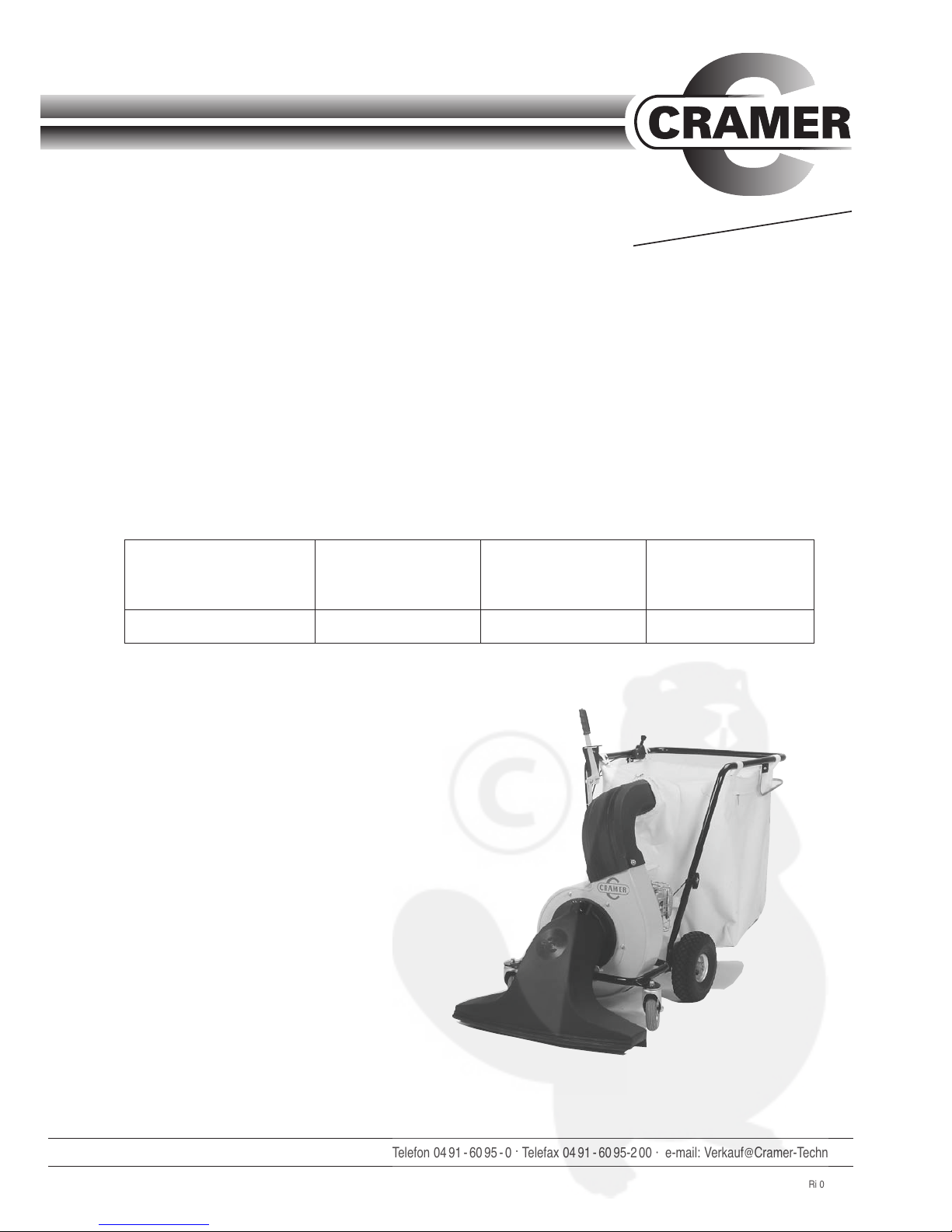
FOLIAGE- and WASTEVACUUM-CLEANER
Operating Instructions
Design: 03
CRAMER-TECHNIK GmbH .Postfach 12 69 .D-26762 Leer .Telefon 04 91- 6095 -0 .Telefax 04 91- 6095-2 00 · e-mail: Verkauf@Cramer-Technik.de
Contents:
1. Scope of Application
2. Description
3. Safety Instructions
4. Operation
5. Maintenance Instructions
6. Spare Parts
7. Troubleshooting
8. Technical Data
9. Spare Parts Drawing
10. Spare Parts List
Ri 02/18/01
You have purchased
the following model
(as marked)
Maschine-Nr.
LS 5000 LS 5000 H
LS 3500
T
op
-
T
echnique for the Gar
den
Page 2
1. Scope of Application
(The digits in text correspond to the item numbers on spare part list.)
- This machine is approved for use as a foliage and
garden waste vacuum (by converting the machine into a foliage blower) as described in these
operating instructions.
- The machine must not be used for any other purpose. The manufacturer shall not be liable for
damage resulting from improper use of the equipment. In such cases the user shall bear sole responsibility.
- Proper use includes observation of the operating,
maintenance and repair instructions given by the
manufacturer.
- Only personnel who are familiar with the machine
and possible dangers should be allowed to operate or repair the machine.
- The relevant accident prevention regulations and
generally recognized safety rules shall be observed.
- Unauthorized changes to the machine relieve the
manufacturer from any liability for damages that
might result therefrom.
2. Description
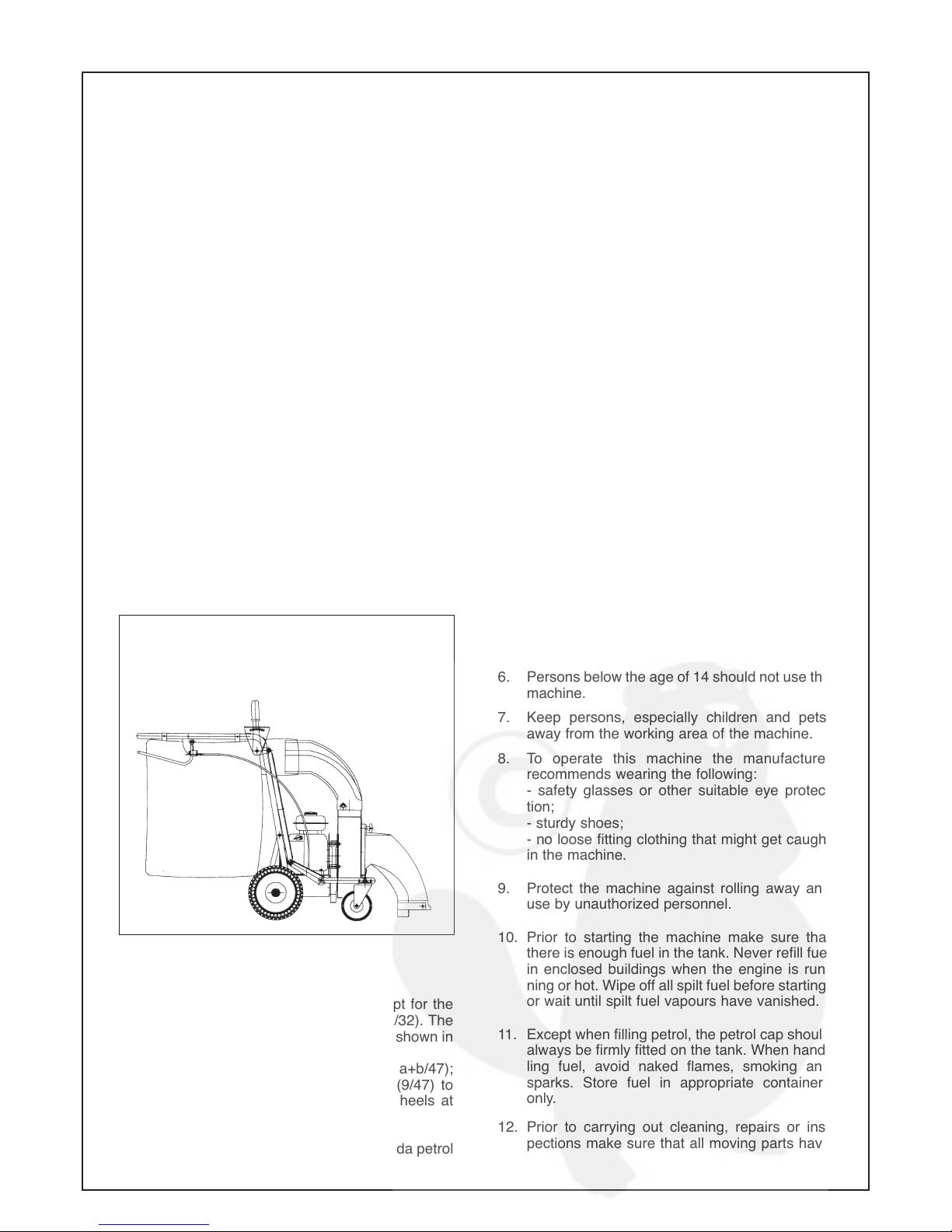
The machine comes pre-assembled except for the
foliage bag (8) and the suction nozzle (25/32). The
suction nozzle and bag should be fitted as shown in
Fig. 1.
The vacuum body has 4 wheels (9/36/46a+b/47);
hard rubber steering wheels at the front (9/47) to
resist damage by thorns, cushion tyred wheels at
the rear (36/46).
The drive consists of a 2.6 or 3.75 kW Honda petrol
engine. Model LS 3500 does not have a wheel
drive, model LS 5000 features a wheel drive. The
working width is 80 cm. A hand lever (27) is provided on the steering handle to adjust the suction
height of the nozzle (3).
The machine can be converted into a foliage blower
(see 4. Operation for further details).
For further technical data please refer to the table in
Section 7.
3. Safety Instructions
1. Always check machine for roadworthiness and
operating safety prior to use.
2. Observe all valid safety and accident prevention regulations in addition to these operating
instructions.
3. Read and understand these operating and
maintenance instructions and make sure that
you are familiar with the control elements and
their proper use.
4. Do not allow personnel to use the machine until
they have read these instructions. Save
instructions for future reference and ordering of
spare parts.
5. Make yourself familiar with all features and
control elements and with their functions prior
to operating the machine.
6. Persons below the age of 14 should not use the
machine.
7. Keep persons, especially children and pets,
away from the working area of the machine.
8. To operate this machine the manufacturer
recommends wearing the following:
- safety glasses or other suitable eye protection;
- sturdy shoes;
- no loose fitting clothing that might get caught
in the machine.
9. Protect the machine against rolling away and
use by unauthorized personnel.
10. Prior to starting the machine make sure that
there is enough fuel in the tank. Never refill fuel
in enclosed buildings when the engine is running or hot. Wipe off all spilt fuel before starting,
or wait until spilt fuel vapours have vanished.
11. Except when filling petrol, the petrol cap should
always be firmly fitted on the tank. When handling fuel, avoid naked flames, smoking and
sparks. Store fuel in appropriate containers
only.
12. Prior to carrying out cleaning, repairs or inspections make sure that all moving parts have
Vac assembly
Please see enclosed mounting
instructions
Fig. 1
Page 3

completely stopped. The engine ignition lever
should be set to »0« position so that the engine
cannot be started accidentally. In addition, the
gas lever must be in »Stop« position.
13. Never leave the machine unattended while the
engine is running.
14. Never run the engine in closed rooms: Danger of
intoxication!
15. Do not place hands or feet under the suction
nozzle or near rotating parts.
16. The area to be vacuumed should be clear of stones, wires etc. which could be picked up by the
rotor and flung in any direction, causing injury to
the operator or bystanders.
17. Do not vacuum materials that could clog the
rotor.
18. Always switch off the engine and wait until the
rotor has stopped completely before doing the
following:
1. Removing the foliage bag or clearing a blockage in the infeed channel, or
2. Removing the suction nozzle or clearing a
blockage in the suction nozzle
3. Repairs, adjustments or removal of foreign
items.
19. When using the foliage vacuum as a foliage blower, the protective cover at the rotor inlet has to
be properly fitted. The blower should not be pointed at persons.
20. The foliage bag should be cleaned at regular
intervals to guarantee proper filter performance.
21. Never empty the foliage bag when the engine is
running.
22. Never replace the suction nozzle or suction tube
while the engine is running.
23. Use only manufacturer’s approved accessories
and original spare parts.
24. Only qualified personnel should be allowed to
carry out repairs and maintenance.
4. Operation
As mentioned in section 2 the machine is pre-assem-
bled in the works with the exception of the foliage bag
and suction nozzle.
Fit the suction nozzle (3) and foliage bag (8) as shown
in Fig. 1, paying particular attention to the adjustment
of the Bowden cable (25/32) for the switch bar (31) to
prevent slipping of the engine clutch.
The engine is started by means of a recoil starter,
after first having set the ignition lever to »1« and the
gas lever to »start«. For further information, please
refer to the attached instructions of Honda.
The suction power of the rotor (51) is largely depen-
dent upon the height of the suction nozzle, (3) i.e. the
heavier the material to be picked up, the lower it
should be (right down for moist foliage and higher for
dry foliage).
The front and sides of the foliage bag (8) are fitted
with air-permeable filter material. The upper and rear
surface is less permeable out of consideration for the
operator. When large volumes of air are sucked in, i.e.
with a high position of the suction nozzle, additional filter surfaces can be created by opening the zips on
the right and left.
The foliage bag is full when the machine tends to tip
backwards, lifting the suction nozzle (3) at the front. In
this case the foliage bag (8) should be emptied by
opening the circumferential zip on the back and emptying it by means of the handle provided on the front
side. The opened part of the bag can be folded up out
of the way by means of a Velcro fastener.
Model LS 3500 has to be pushed over the surfaces to
be cleaned. Model LS 5000/LS 5000 H has a self-propelled drive which is started by means of the switch
bar (31) on the steering handle. Model LS 5000/LS
5000 H features free-wheeling ball bearings for curve
negotiating ability (38).
How to convert the foliage vaccum (3) into a foliage
blower: Unscrew the suction nozzle and the outlet
connecting piece (7). To cover the two openings, fit
the guard (59) supplied as an accessory. Then pull
back the locking plate (24) at the back to release the
lock and turn the rotor body (51) by approx. 90 deg.
(in counter-clockwise direction seen from the front of
the machine).
Caution:
rotation in the wrong direction might
damage cable to contact switch (5).
5. Maintenance Instructions
Strong vibrations arise when vac is on. It is therefore necessary to check screw tightness after a
few working hours.
Always set the ignition lever of the engine to »0« prior
to carrying out maintenance or repairs. To clean the
foliage bag (8), release the bag from the outlet (7)
connecting piece and undo the retaining straps. The
filter material of the foliage bag will eventually become
clogged. In this case, turn the bag inside out and
shake it out completely, or wash foliage bag in a water
bath or by rinsing with water; industrial cleaning is
also possible.
From time to time the suction nozzle (3) at the front of
the machine should be dismantled and the blower
rotor (14) inspected for damage caused by foreign
items.
Check the air pressure of the rear wheels (36/46a+b)
occasionally according to the technical data.
The drive engine should be serviced as described in
Page 4

the attached instructions of Honda.
All bearing points of the foliage vacuum have self-
lubricating ball bearings and do not have to be lubricated.
Model LS 5000/LS 5000 H: check drive after a longer
period of working time (depending on the type of
ground the vac is used on). Loosen the four screws
holding the bottom plate to uncover the complete
driving mechanism (45/66). Wear may have loosened the wheel driving chain (41/74). To adjust
distance again, loosen shaft bearings (42) and turn
bearings (42) in slot. Tighten screws carefully.
The air filter of the drive engine should be cleaned or washed out frequently because handling
foliage always involves a lot of dust.
6. Spare parts
A spare parts drawing and spare parts list is attached. Please identify the required spare parts
according to the drawing and state the article numbers given in the spare parts list on all orders.
7. Troubleshooting
8. Technical Data
Model 3500 Model 5000 Model 5000 H
Drive: Petrol engine type Honda Petrol engine type Honda Petrol engine type Honda
3.5 HP/2.6 kW 5 HP/3.75 kW 5 HP/3.75 kW
Consumption: 1.1 l/h 1.5 l/h 1.5 l/h
Noise level
without load: 66 db(A) 66 db(A) 66 db(A)
full load: 91 db(A) 91 db(A) 91 db(A)
Tyres
front: dia. 180 x 45 dia. 180 x45 dia. 180 x45
rear: dia. 300 x400-4 dia. 300 x400-4 dia. 300 x400-4
Air pressure, rear tyres: 1,8 bar 1,8 bar 1,8 bar
Weight (kg): 67 70 75
Dimensions:
L(mm) 157 157 157
W (mm) 70 70 70
H (mm) 105 105 105
Bag capacitiy: 240 240 240
Working width (cm): 80 80 80
Wheel drive: no yes yes
Fault: Cause: Solution:
1. Engine won’t start – Ingnition switch on engine in – Turn ignition switch to
»0« position »1« position
2. No engine power – Fuel tank empty – Refill fuel
– Sparking plug defective – Exchange sparking plug
– Fuel line blocked or – Empty fuel line and tank
water in petrol and refill new petrol
– Air filter soiled – Clean (rinse) air filter
3. Engine gets too hot – Carburettor not adjusted – Adjust carburretor acc. to
correctly Honda instructions
– Insufficient engine oil – Top up with engine oil
4. No suction power – Foliage bag too full – Empty foliage bag
– Filter area of foliage bag – Wipe filter areas
soiled (dry clean if necessary)
– Suction nozzle blocked – Clean suction nozzle
5. Wheel drive slip – Gear clutch is slipping – Shorten Bowden cable for
switch bar by shifting
clamping piece
Page 5

9. Spare Parts Drawing
Page 6

10. Spare Parts List
LS 3500 LS 5000 LS 5000 H
Item Description No. of drawing Art.-No. Art.-No. Art.-No.
1 Rubber strip 670.01-01-006 99.5.7000 99.5.7000 99.5.7000
2 Clamping strip 670.01-01-005 99.5.7001 99.5.7001 99.5.7001
3 Suction nozzle LS 99.5.7002 99.5.7002
4 Star-grip nut M10x25 99.5.7078 99.5.7078 99.5.7078
5 Contact switch 99.5.7004 99.5.7004
6 Hexagon bolt DIN 933-M10x25 99.5.7005 99.5.7005 99.5.7005
7 Outlet connecting piece 99.5.7006 99.5.7006
8 Foliage bag 99.5.7007 99.5.7007
9 Steering wheel assy (steel-rim) 99.5.7008 99.5.7008
10 Lock nut DIN 985-M12 99.5.7009 99.5.7009 99.5.7009
11 Plastic bushing 670.01-01-002 99.5.7010 99.5.7010 99.5.7010
12 Washer DIN 125-Ø13 99.5.7011 99.5.7011 99.5.7011
13 Hexagon bolt DIN 933-M12x35 99.5.7012 99.5.7012 99.5.7012
14 Rotor (20 mm ø) LS 5000 670.01-11 99.5.7013 99.5.7013
15 Feather key DIN 6886-A5x5x63 99.5.7014 99.5.7014 99.5.7014
16 Top pulley SPZ 50x1 99.5.7015 99.5.7015
17 Taper bushing PN 20-1610 99.5.7016 99.5.7016
18 Bottom pulley SPZ 150x1 99.5.7017 99.5.7017
19 V-belt XPZ 687 99.5.7018 99.5.7018
20 Flange bearing RA 20 99.5.7019 99.5.7019
21 Tension spring 99.5.7020
22 Feather key A5x5x25 99.5.7048 99.5.7048
23 Tightener 670.01-09 99.5.7021
23a Tightener 675.01-09 99.5.7088
24 Locking plate 670.01-25 99.5.7022 99.5.7022 99.5.7022
25 Bowden cable (gas lever) 99.5.7023
26 Adjusting rod 670.01-12 99.5.7024 99.5.7024 99.5.7024
27 Adjusting lever 670.01-13 99.5.7025 99.5.7025 99.5.7025
28 Handle 30x4 99.5.7026 99.5.7026 99.5.7026
29 Compression spring 590.01-01-009 99.5.7027 99.5.7027 99.5.7027
29a Washer DIN 125-Ø8.4 99.5.7028 99.5.7028 99.5.7028
29b Hexagon bolt DIN 933-M8x35 99.5.7029 99.5.7029 99.5.7029
29c Washer (plastic) 99.5.7030 99.5.7030
29d Nut DIN 985-M8 99.5.7031 99.5.7031 99.5.7031
30 Gas lever assy 99.5.7032
31 Switch bar 670.01-14 99.5.7033 99.5.7033
32 Bowden cable (drive) 99.5.7034
32a Adjustment-screw 99.5.7077 99.5.7077
33 Circlip DIN 471-20x1.2 99.5.7035 99.5.7035 99.5.7035
35a Shaft with sprocked wheel 675.01-16 99.5.7090
35b Shaft with sprocked wheel 670.01-16 99.5.7100
36 Cushion-tyred wheel (plastic-rim) 99.5.7038
39 Washer DIN 9021-Ø8.4 99.5.7041 99.5.7041
40 Hexagon bolt DIN 933-M8x20 99.5.7042 99.5.7042
41 Chain 670.01-01-008 99.5.7043
42 Flange bearing RA 20 99.5.7019 99.5.7019
43 Sprocket wheel 670.01-10-002 99.5.7045 99.5.7045
44 Split taper pin DIN 1481-4x16 99.5.7046 99.5.7046
45 Gearbox 670.01-10-004 99.5.7047
46 Cushion tyred wheel (steel-rim) 99.5.7060 99.5.7060
46a Cushion tyred wheel (steel-rim) right with bearing and free-wheel 99.5.7101 99.5.7101
46b Cushion tyred wheel (steel-rim) left with bearing and free-wheel 99.5.7102 99.5.7102
47 Steering wheel (plastic-rim) 99.5.7061
48 axle 660.01-06 99.5.7062
49 Rotor ø 18 mm LS 3500 660.01-07 99.5.7075
50 Distance-bush 660.01-01-002 99.5.7076
51 Housing 670.03-02 99.5.7071 99.5.7071 99.5.7071
52 Frontplate housing 670.02-20 99.5.7067 99.5.7067 99.5.7067
53 Motorplate LS 3500 660.02-02 99.5.7072
54 Motorplate LS 5000 670.02-05 99.5.7073 99.5.7073
55 Screw for protection DIN 603-M8x20 99.5.7070 99.5.7070 99.5.7073
56 Starlock-cap D20 99.5.7079
57 Washer DIN 125-Ø21 99.5.7080
58 Split taper pin DIN 1481-6x40 99.5.7081
59 Safety-guard 670.02-18 1429 423 1429 423 1429 423
60 Suction tube with accessories 670.01-28 1429 417 1429 417 1429 417
66 Gearbox 675.01-10 99.5.7089
68 Chain protection wheel shaft 675.01-15 99.5.7091
69 Bowden cable (drive) 675.01-14 99.5.7092
70 Operating handle 675.01-06 99.5.7093
72 Shaft for blower 675.01-12 99.5.7095
73 Pulley guide incl. sprocket 675.01-08 99.5.7096
74 Chain - Gearbox 675.01-01-003 99.5.7097
75 Chain for rotor drive 675.01-01-004 99.5.7098
76 Regulating device (operating handle) 675.01-13 99.5.7099
77 Sprocket - Gearbox H (pos. 66) 675.01-10-003 99.5.7104
 Loading...