

Page 1

OWNER'S
MANUAL
Model No.
919.679370
IMPORTANT:
Read the Safety Guidelines
and All Instructions Carefully
Before Operating
Sold by Sears Canada, Inc., Toronto, Ont. M5B2B8
120/240 ¥OLT • 3750 WATT
GENERATOR
SAFETY GUIDELINES
ASSEMBLY
OPERATION
MAINTENANCE
TROUBLESHOOTING
REPAIR PARTS
MGP-679370A 8/12/99
Page 2

TABLE OF CONTENTS
Warranty.....................
Safety Guidelines......
Assembly....................
Operation ..................
Maintenance..............
Service Adjustments
DATE PURCHASED:.
MODEL NO:
SERIAL NO:
STORE WHERE PURCHASED:
ADDRESS
CITY
TELEPHONE;
Record the above information about your unit
so that you will be able to provide it in case
of loss or theft.
....... 2
.... 3-8
....... 8
.. 9-13
13-15
..... 15
Storage................................................... 15
Troubleshooting..................................... 16
Parts.................................................. 17-31
EPA Codes........................................ 32-33
How To Order Parts ................. Back Cover
Français
HORSE POWER 7.5 HP
GASOUNE CAPACITY 4 GALLON
OIL CAPACITY 30 OZ.
MAINTENANCE AGREEMENT
The Craftsman Warranty, plus a Maintenance Agreement,
provide maximum value for your Sears products. Contact
your nearest Sears store for details.
CUSTOMER RESPONSIBILITIES
Read and observe the safety rules.
Follow a regular schedule in maintaining, caring for and us
ing your generator.
Follow the instructions under “Customer Responsibilities”
and “Storage” sections of this owner's manual.
FULL ONE YEAR WARRANTY ON CRAFTSMAN GENERATORS
For one year from the date of purchase, when this Craftsman generator is maintained and operated according to the
instructions in this owner’s manual, Sears will repair, free of charge, any defect in material and workmanship.
If your Craftsman Generator is used for commercial or rental purposes, this warranty applies for only 90 days from the
original date of purchase.
FULL ONE YEAR WARRANTY ON CRAFTSMAN ENGINE
For one year from the date of purchase, when this Craftsman engine is maintained and operated according to the
instructions in this owner’s manual. Sears will repair, free of charge, any defect in material and workmanship.
If your Craftsman engine is used for commercial or rental purposes, this warranty applies only for 90 days from the date
of purchase. This warranty does not cover: Expendable items such as spark plugs and air filters, which become worn
during normal use.
Repairs necessary because of operator abuse or negligence, including damage resulting from no oil being supplied to
the engine or failure to maintain the equipment according to the instructions contained in this owner’s manual, are not
covered under warranty.
WARRANTY SERVICE IS AVAILABLE BY RETURNING THE GENERATOR TO THE NEAREST SEARS SERVICE CENTER.
This warranty gives you specific legal rights and you may also have other rights, which vary from PROVINCE TO
PROVINCE,
Sold by Sears Canada^ Inc., Toronto, Ont.
2 - ENG
Page 3
SAFETY GUIDELINES - DEFINITIONS
This manual contains information that
is important for you to know and
understand. This information relates
to protecting YOUR SAFETY and
PREVENTING EQUIPMENT PROB
LEMS. To help you recognize this
information, we use the symbols to
the right. Please read the manual and
pay attention to these sections.
IMPORTANT SAFETY INSTRUCTIONS
When using this product basic precautions should always be followed
A DANGER
URGENT SAFETY INFORMATION - A HAZ
ARD THAT WILL CAUSE SERIOUS INJURY
OR LOSS OF LIFE.
AWARNING
IMPORTANT SAFETY INFORMATION - A
HAZARD THAT MIGHT CAUSE SERIOUS
INJURY OR LOSS OF LIFE.
• SAVE THESE INSTRUCTIONS •
Information for preventing damage to
equipment.
Information that you should pay
special attention to.
AWARNING
including the following:
I..............................
NOTE
3
..R..ISK
HAZARD
Attempting to connect generator directly
to the electrical system of any building
structure.
Inadequate electrical grounding of gen
erator.
A DANGER
.........
Back feeding electricity through a
building’s electrical system to the
outside utility feed lines could en
danger repair persons attempting to
restore service.
Attempting to connect to the incoming
utility service could result in electrocu
tion.
Restoration of electrical service while
the generator is connected to the in
coming utility could result in a fire or
serious damage if a isolator switch is
not installed.
The failure of one of the generator’s
electrical devices, a broken wire, wet
surfaces, etc. could result in the entire
unit becoming electrically charged.
Contact with electrically charged
surfaces could result in electrocution.
Q.F
.....
ELECTROCUIIOM
......
AM.D..FI.B..E
WHAT COULD HAPPEM HOW TO PREVENT IT
Never back feed electricity through a
structure's electrical system.
To connect to a structure's electrical
system in a safe manner and always
have a Double-Throw Transfer Switch
installed by a qualified electrician, in
compliance with local ordinances.
(When installing a Double-Throw
Transfer Switch, a minimum of 10
gauge wiring must be used.)
Make sure that the unit is connected
to an appropriate electrical ground,
in accordance with the requirement
of the National Electric Code. See
page 8 for grounding instructions.
3 - ENG
Page 4

>iUli
READ AND UNDERSTAND ALL WARNINCS BEFORE
ATTEMPTING TO OPERATE GENERATOR.
ADANGER
RISK OF ELECTROCUTION AND FIRE iconrcii
HAZARD
Operation of generator in rain, wet, icy,
or flooded conditions.
Use of worn damaged, undersized or un
grounded extension cords.
WHAT COULD HAPPEN HOW TO PREWEIT IT
Water is an excellent conductor of
electricity! Water which comes in
contact with electricity charged
components can transmit electricity to
the frame and other surfaces, resulting
in electrical shock to anyone contact
ing them.
Contact with worn or damaged exten
sion cords could result in electrocution.
Use of undersize extension cords could
result in overheating of the wires or at
tached items, resulting in fire.
Use of ungrounded cordsets could pre
vent operation of circuit breakers and
result in electrical shock.
Operate generator in a clean, dry,
well ventilated area. Make sure
hands are dry before touching unit.
Inspect extension cords before use
and replace with new if required.
Use proper size (wire gauge) cordset
for application.
Always use electrically grounded
cordset.
Placing generator on or against highly
conductive surface, such as a steel
walkway or metal roof.
Improper connection of items to gen
erator.
Operation of unit when damaged, or with
guards or panels removed.
Accidental leakage of electrical current
could charge conductive surfaces in
contact with the generator.
Exceeding the load capacity of the gen
erator by attaching too many items, or
items with very high load ratings to it
could result in overheating of some
items or their attachment wiring result
ing in fire or electrical shock.
Attempting to use the unit when it has
been damaged, or when it is not func
tioning normally could result in fire or
electrocution.
Removal of guarding could expose elec
trically charged components and result
in electrocution.
4 - ENG
Place generator on low conductivity
surface such as a concrete slab.
Read the load rating chart and in
structions on page 9, 10 and 11.
Make sure that the summation of
electrical loads for all attachments
does not exceed the load rating of
the generator.
Do not operate generator with me
chanical or electrical problem. Have
unit repaired by an Authorized Ser
vice Center.
Do not operate generator with pro
tective guarding removed.
Page 5
READ AND UNDERSTAND ALL WARNINGS BEFORE
ATTEMPTING TO OPERATE GENERATOR.
AWARNING
RISK OF FIRE
HAZARD
Attempting to fill the fuei tank while the
engine is running.
Sparks, fire, hot objects Cigarettes, sparks, fires, or other hot
Improper storage of fuel Improperly stored fuel could lead to ac
Inadequate ventilation for generator Materials placed against or nearthe gen
WHAT COULD HAPPEN HOW TO PREWEiT IT
Gasoline and gasoline vapors can
become ignited by coming in contact
with hot components such as the
muffler, engine exhaust gases, or from
an electrical spark.
objects can cause gasoline or gasoline
vapors to ignite.
cidental ignition. Fuel improperly secured
could get into the hands of children or
other unqualified persons.
erator or operating the generator in ar
eas where the temperature exceeds 104°
F. ambient can interfere with its proper
ventilation features causing overheating
and possible ignition of the materials.
Turn engine off and allow it to cool
before adding fuel to the tank. Equip
area of operation with a fire extin
guisher certified to handle gasoline
or fuel fires.
Add fuei to tank in well ventilated
area. Make sure there are no sources
of ignition nearthe generator.
Store fuel in a container designed to
hold gasoline. Store container in se
cure location to prevent use by oth
ers.
“Operate generator in a clean, dry,
well ventilated area a minimum of four
feet from any objects or wall, DO
NOT OPERATE UNIT INDOORS OR
IN ANY CONFINED AREA.
Tampering with factory set engine speed
settings.
Overfilling the fuel tank - fuel spillage. Spilled fuel and its vapors can become
Engine speed has been factory set to
provide safe operation. Tampering with
the engine speed adjustment could re
sult in overheating of attachments and
could cause a fire.
ignited from hot surfaces or sparks.
5 - ENG
Never attempt to “speedup” the en
gine to obtain more performance.
Both the output voltage and fre
quency will be thrown out of stan
dard by this practice, endangering
attachments and the user.
Use care in filling the tank to avoid
spilling fuel. Make sure fuel cap is
secured tightly and check engine
for fuel leaks before starting
engine. Move generator away from
refueling area or any spillage before
starting engine. Allow for fuel
expansion. Keep maximum fuel
level % inch below the tip of the
fuel tank. Never refuel with the
engine running.
Page 6
READ AND UNDERSTAND ALL WARNINGS BEFORE
ATTEMPTING TO OPERATE GENERATOR.
A DANGER
Risk of lniur¥ and Propertw Damage When
Transporting Generator
HAZARD
Fire, Inhalation, Damage to Vehicle
Surfaces
WHAT COULD HAPPEN
Fuel or oil can leak or spill and could
result in fire or breathing hazard, seri
ous injury or death can result. Fuel or oil
leaks will damage carpet, paint or other
surfaces in vehicles or trailers.
A DANGER
HOW TO PREVENT IT
If generator is equipped with a fuel
shut-off valve, turn the valve to the
off position before transporting to
avoid fuel leaks. If generator is not
equipped with a fuel shut-off valve,
drain the fuel from tank before trans
porting. Only transport fuel in an CSA
approved container. Always place
generator on a protective mat when
transporting to protect against dam
age to vehicle from leaks. Remove
generator from vehicle immediately
upon arrival at your destination
RISK OF BREATHING - INHALATION HAZARD
HAZARD
Gasoline engines produce toxic carbon
monoxide exhaust fumes.
WHAT COULD HAPPEN
Breathing exhaust fumes wiil cause se
rious injury or death.
6 - ENG
HOW TO PREVENT IT
Operate generator in clean, dry, well
ventilated area. Avoid enclosed ar
eas like garages, basements, stor
age sheds, etc., which lack a steady
exchange of air. Never operate unit
in a location occupied by humans or
animals. Keep children, pets and oth
ers away from area of operating unit.
Page 7
READ ÄND UNDERSTAND ALL WARNINGS BEFORE
ATTEMPTING TO OPERATE GENERATOR.
AWARNING
RISK OF UNSAFE OPERATION
HAZARD
Operation of generator in careless
manner.
Operation of voltage sensitive appli
ances without a voiiage surge protec
tor.
WHAT COÜLD HAPPEN HOW TO PREWENT IT
Ail sources of energy include the poten
tial for injury. Unsafe operation or main
tenance of your generator couid iead to
serious injury or death to you or others.
Review and understand all of the
operating instructions and warn
ings in this manual.
Become familiar with the operation
and controls of the generator.
Know how to shut it off quickly.
Equip area of operation with a fire
extinguisher certified to handle
gasoline or fuel fires.
Keep children or others away from
the generator at all times.
Any gasoline operated household gen
erator will incur voltage variations caus
ing damage to voltage sensitive appli
ances or result in fire.
Always use U.L. listed voltage pro
tector to connect voltage sensitive
appliances (TV, computer, stereo,
etc.). Failure to use a U.L. listed volt
age surge protector will void the war
ranty on your generator.
Notice: A multiple outlet strip is not
a surge protector make sure you use
a U.L. listed voltage surge protector.
HAZARD
Contact with hot engine and generator
components.
HAZARD
Contact with moving parts can result in
serious injury.
AWARNING
RISK OF HOT SURFACES
WHAT COULD HAPPEN HOWTO PREVENT IT
Contact with hot surfaces, such as en
gines exhaust components, could result
in serious burns.
During operation, touch only the con
trol surfaces of the generator. Keep
children away from the generator at
all times. They may not be able to
recognize the hazards of this prod
uct.
RISK OF MOVING PARTS
WHAT COULD HAPPEN HOW TO PREVENT IT
The generator contains parts which ro
tate at high speed during operation.
These parts are covered by guarding to
prevent injury.
7 - ENG
Never operate generator with guard
ing or cover plates removed. Avoid
wearing loose fitting clothing or jew
elry which could be caught by mov
ing parts.
Page 8
READ AND UNDERSTAND ALL WARNINGS BEFORE
ATTEMPTING TO OPERATE GENERATOR.
AWARNING
RISK FROU LIFTING
HAZARD
Lifting a very heavy object. Serious injury can result from attempt
ik WARNING
This product is not equipped with a spark arresting muffler. If the product will be used around flammable materials, or on
land covered with materials such as agricultural crops, forest, brush, grass, or other similar items, then an approved spark
arrester must be installed and is legally required in the state of California. It is a violation of California statutes section
130050 and/or sections 4442 and 4443 of the California Public Resources Code, unless the engine is equipped with a spark
arrester, as defined in section 4442, and maintained in effective working order. Spark arresters are also required on some
U.S. Forest Service land and may also be legally required under other statutes and ordinances.
Engine exhaust contains chemicals known, in certain quantities, to cause cancer, birth defects or other reproductive harm.
Read Owner’s Manual. Do not operate equipment until you have read Owner’s Manual for
Safety. Operation, and Maintenance Instructions.
WHAT COULD HAPPEN HOW TO PREWEIT IT
The generator is too heavy to be lifted
ing to lift too heavy an object.
by one person. Obtain assistance
from others before you try to move
it.
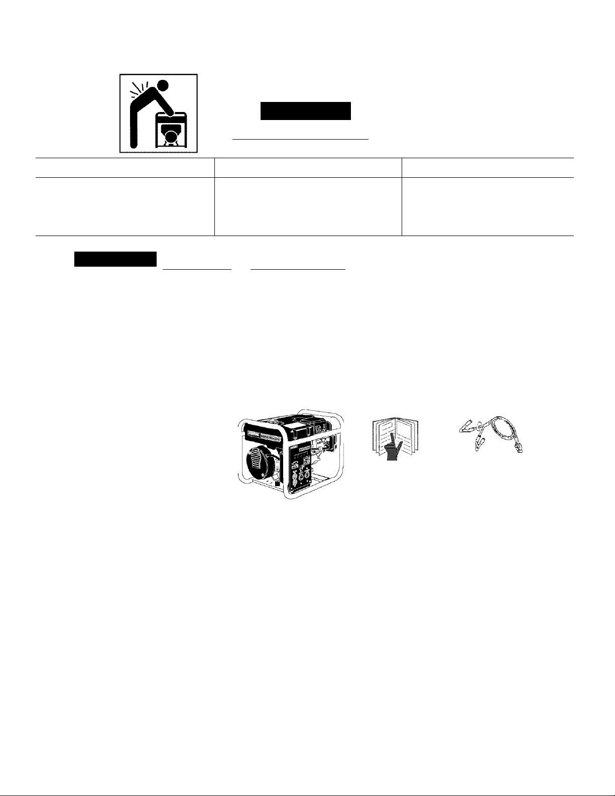
CARTON CONTENTS
® Main Unit
® Owner's Manual
• Battery Charge Cables
Owner's Manual
Battery Charge Cables
Main Generator Unit
CAUTION: Read owner’s manual. Do not attempt to
operate equipment until you have read Owner’s
Manual for Safety, Operation, and Maintenance In
structions.
REMO¥E GENERATOR FROM CARTON
® Open carton from top.
• Cut carton along dotted lines.
• Remove all carton inserts.
• Remove generator through opening in carton.
IMPORTANT: Before any attempt to start your generator
be sure to check engine oil (See OPERATION under
Engine Oil on page 11)
8 - ENG
GROUNDING THE GENERATOR
This generator should be grounded to help prevent
accidental electrical shock. Shown below is a picture of
the grounding lug supplied on your generator. First, drive
a 3/4" or 1" diameter copper pipe or rod into the ground
close to the generator set. The pipe must penetrate moist
earth. Using #10 gauge wire, connect one end of the wire
into the grounding lug. Next, connect the other end of the
wire to the copper pipe or rod using an approved ground
clamp.
o
o
Grounding Lug
o
Page 9
OPERATION
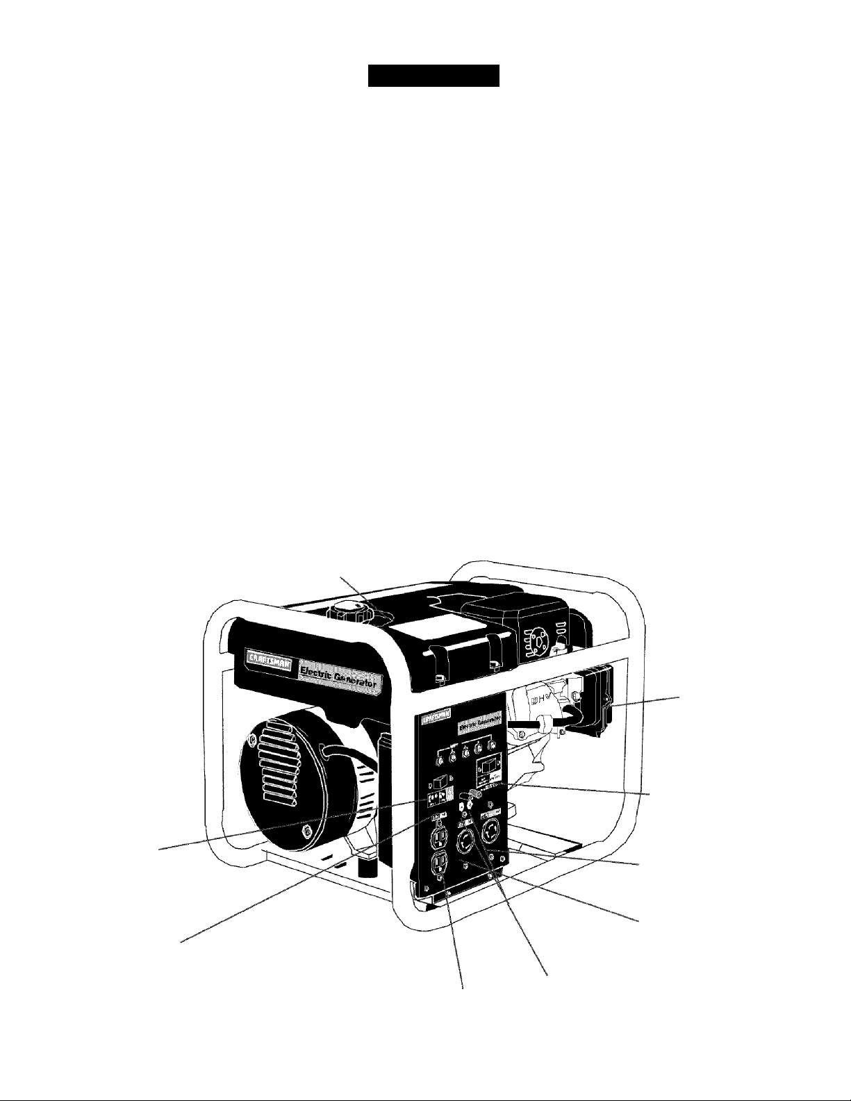
KNOW YOUR GENERATOR
Read this Owner’s Manual and Safety Rules be
fore operation of your Generator. Compare this
illustration with your generator to familiarize yourself
with the location of various controls and adjustments.
Save the manual for future references.
FUEL TANK- Capacity of 4 US gallons.
CHOKE SWITCH- Lever used to start, cold engine.
ENGINE RUN/STOP SWITCH- Sets engine in starting
mode for recoil start.er - Stops running engine.
ENGINE OIL FILL- Place where engine oil is poured.
CIRCUIT BREAKER- Each receptacle has a circuit
breaker to protect the generator from overloading.
120 ¥OLT DUPLEX RECEPTACLES- Used to supply 1800
watts of electrical power per receptacle for operations.
Protected by 15 amp circuit breaker.
120/240 VOLT TWISTLOCK RECEPTACLE- Used to
supply 1800 watts of electrical power for 120 volt operations
and for 240 volt operation 3750. Will only supply 1875 watts
each if both receptacles are being used. Protected by 15
amp circuit breaker.
120 VOLT TWISTLOCK RECEPTACLE- Used to supply
1800 watts of power per receptacle protected by a 15 amp
circuit breaker.
AIR CLEANER- Includes filter element and foam pre-cleaner
that limits the amount of dirt, that enters the engine.
FULL POWER SWITCH - Switch used to convert, every
receptacle on the panel, when placed in the 120 position,
to a 120 volt receptacle. This will allow you to receive the
full capacity of the generator by using all 120 volt recep
tacles. When in the 120/240 position, you will only be able
to use half of the 3750 watts when using the 120 volt recep
tacles. But in this position, the full 3750 watts can be re
ceived in the 240 twistlock receptacle.
IDLE CONTROL SWITCH- When on, allows the engine to
run at a lower speed when there is no load on the generator.
FULL
POWER
SWITCH
CIRCyiT
BREAKERS
FUEL TANK
120 DUPLEX
RECEPTACLES
AIR CLEANER
IDLE CONTROL
SWITCH
120/240
TWISTLOCK
RECEPTACLE
120 TWISTLOCK
RECEPTACLE
12 VOLT DC
CHARGES
9 - ENG
Page 10
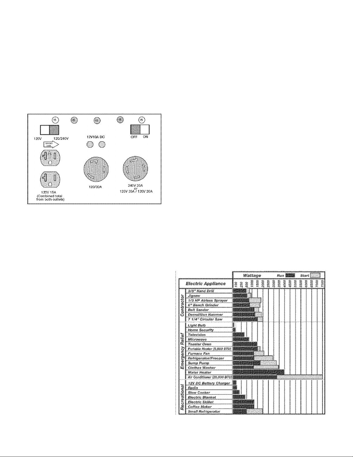
RECEPTACLES
Your generator is equipped with duplex 120 volt receptacle
a 120 twistlock and a 120/240 volt twistlock receptacle.
The unit is also equipped with a 15 amp circuit breaker for
the duplex 120 volt receptacles, a 15 amp circuit breaker
for the 120 volt twistlock receptacle and a 15 amp circuit
breaker for the 120/240 volt twistlock receptacle. If the cir
cuit breaker trips, unplug all electrical loads from the gen
erator. Let the circuit breaker cool down. Push circuit breaker
button to reset.
FULL POWER SWITCH
Your Craftsman generator has a full power switch on the
control panel. This switch has two positions: 120 VOLT
ONLY, and 120/240 VOLT.
120 Position
When placed in the 120 position, (Shown below) every re
ceptacle on the panel will be converted to a 120 volt recep
tacle. 240-volt power is not available. This position allows
full capacity of the generator to be received by using all
120-volt receptacles. While in the 120 position, each re
ceptacle has the ability to reach the maximum 4650 surge
wattage for inductive motors that require 4650 watts or be
low to start.
GENERATOR CAPACITY
Exceeding the rated capacity of your generator can
result in serious damage to your generator and connected
electrical devices. You should observe the following to
prevent overloading the unit:
® Starting and running wattage requirements must be
calculated to match your generator wattage capacity.
• Resistive load appliances such as light bulbs, TV’s
and microwaves, have the same starting and running
wattage. The wattage used for calculating the capacity
can usually be found on each of these appliances.
Some inductive appliances and tools will list on the motor
name plate, the starting and running voltage and amperage
requirements. Use the following formulato convert voltage
and amperage to wattage:
(Volts X Amp = Watts)
inductive load appliances and tools such as refrigerators,
air compressors and washers require approximately 2 to
4 times the listed running wattage for starting the equip
ment. This initial load only lasts for a few seconds on
start-up but is very important when figuring your total
wattage to be used.
NOTE: Always start your largest electric motor first, and
then plug in other items, one at a time.
The guide below is provided to assist you in determining
the appliances and tools that can be ran with the wattage
capacity of your generator.
Го s#feet thm right gmamatm for уоиг fi»ei#s, total tiii» wattmg»
mf ffte Jfe»s fe be run at tfte saw# time.
120 V 120/240V
120/240 Position
When in the 120/240 position, (Shown Below) only half of
the 3750 watts can be received when using the 120-volt
receptacles and the 120/240-volt twistlock receptacle will
be converted to allow the full 3750 watts to be received
from this one receptacle. Also in this position, the 120-volt
receptacles will only reach a maximum of 4650 surge watts.
120 V
120/240V
10 - ENG
Tim штШат mitmas wtmma шт wmrsm*. ШйШзф гтиШтФШ шаг vav
m№ dfffmmnt brands of »ррвтев».
Page 11
OBTAINING ELECTRICITY FROM GENERATOR
There are basically two ways to obtain electricity form a
generator:
® Use of extension cords directly form the generator
to the appliance, lights, tools, etc.
® Use of a double-throw transfer switch installed
directly to the main electrical supply outside of the
house.
® Start the engine. Let it run while the battery charges.
® When the battery is fully charged, stop the engine
and disconnect the battery charge cables from the
panel and battery. Batteries should not be charged
when the unit is unattended.
NOTE: Dd not use t±ifi unit to chaiga any 6-volt tatteries.Do
not use the unit to crank an engine having a discharged
tstbsty.
Extension Cord
When using an appliance or tool at a considerable distance
from the generator, a 3-wire extension cord that has a 3blade grounding plug and 3-slot receptacle that accepts
the tool’s plug should be used. A cord of adequate size
must be used. A minimum of 12 gauge wire size with at
least a 20 amp draw can be used. When amperage
exceeds 20 amps a 10 gauge wire size should be used.
Connecting Generator To Main Electrical Sypply
Potential hazards exist when a electrical generator is con
nected to the main electrical supply coming into the house.
It is at that point that the generator could feed back into the
utility company’s system causing possible electrocution of
workers who are repairing electrical lines. To avoid back
feeding of electricity into utility systems, a double-throw
transfer switch should be installed between the genera
tor and utility power. This device should be Installed by a
licensed electrician and in compliance with all local electri
cal codes.
NOTE: When installing a Double-Throw Transfer Switch,
a minimum of 10 gauge wiring must be used.
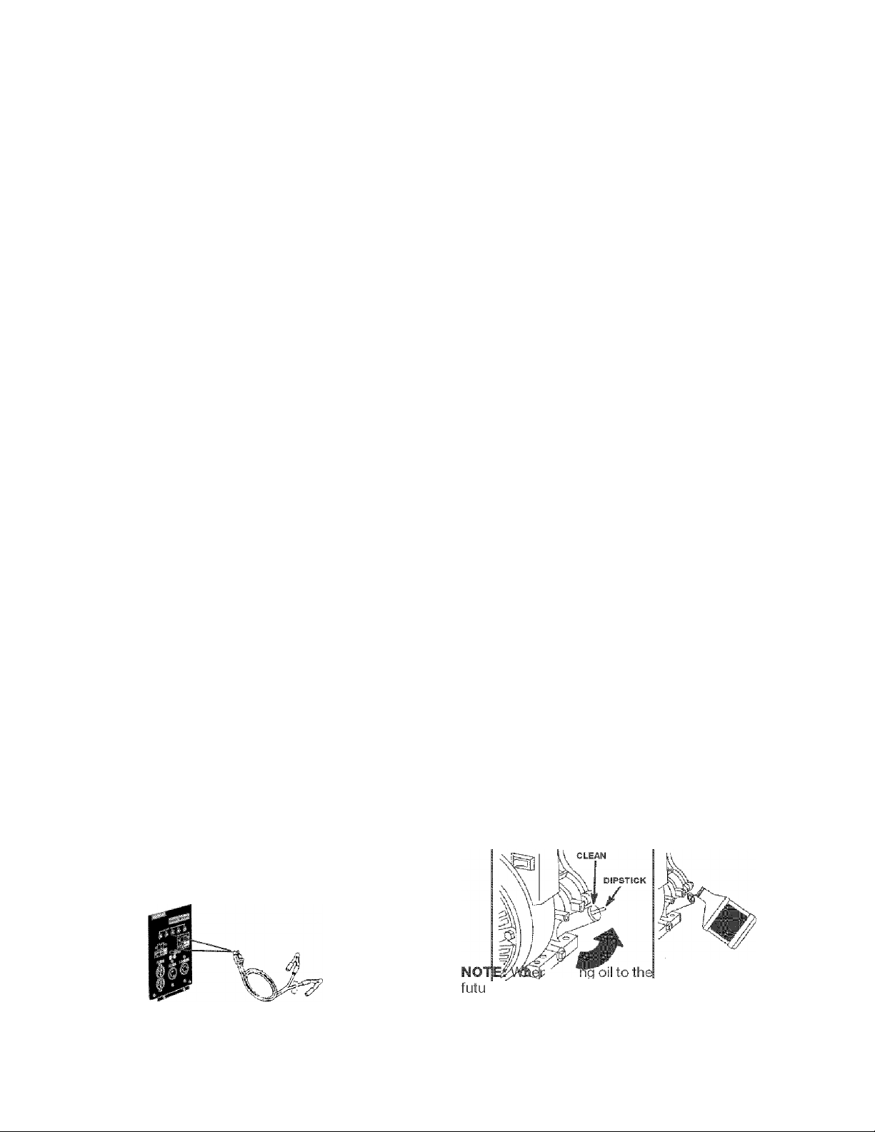
CHARGING A BATTERY
IMPORTANT: Always use safety glasses, rubber gloves
and protective clothing while charging battery.
Your generator has the capability of recharging a 12-volt
storage or automotive battery. To recharge a 12-volt
battery, proceed as follows:
® First, check the fluid level in all of the battery cells.
Add distilled water if necessary. Do not use tap
water.
® Clean battery posts if necessary.
® Connect battery charge cables to panel receptacle.
BEFORE STARTING ENGINE
CAUTION: Always check engine oil level before
every start.. Running engine low of oil or out of oil
could result in serious damage to the engine.
Automatic Idle Control
The automatic idle control switch, when in the ON posi
tion, allows the engine to run at lower speed when there
is no load on the generator. This will lower the engine
noise, save on fuel consumption and engine life. When in
the OFF position the engine will run at 3600 RPM’s
continuous with or without a load.
OFF
NOTE: The idle con mmime OFF position when
operating large motor loads (Refrigerators, freezers, etc.) or
voltage sensitive electronic equipment (TV, computers, etc.)
Engine Oil
Your unit has been shipped without oil in the engine. A
bottle of SAE 30 weight oil is included in the cart.on.
Remove oil dip stick located on the side of engine. The
oil dip stick is clearly marked with a line that tells you
when unit has enough oil. Do not fill above this point.
Pour slowly.
Connect the battery charge cable with the red handle
to the battery post indicated by POS or (+).
Connect the battery charge cable with the black
handlefo the battery post indicated by NEC or (-).
11 - ENG
raddi
rbrase-adiiglTcitrattlTTfe^
Service SF, SG, SH” rated SAE 30 weight. Use no special
additives. Select the oil’s viscosity grade according to
you expected operating temperatures.
engine crankcase iji the
^errtrnixfc
Page 12

gine damage due to lack or lubrication.
Use of SAE30 oil below 40°F (4°C) will result in hard start
ing and possible engine damage due to inadequate lubri
cation.
Low Oil Shytdown
Your Craftsman generator engine is equipped with Low
Oil Shutdown. Low Oil Shutdown is a safetydevice
designed to protect your engine from damage in the
event the oil level in the crankcase is low.
If while the engine is running, the oil gets low, it will
automatically shut itself down and will not restart until the
oil is added. If the oil is low before start-up, the genera
tor will not start until oil is added.
NOTE: The Low Oil Shutdown mechanism is very sensi
tive. You must fill the engine to the full mark on the
dipstick to inactivate this safety device.
• Remove gas cap
• Add unleaded gasoline, slowly, to fuel tank.
• Do not overfill.
• On the engine there is a choke/run lever. Place lever
to the choke position.
Gasoline
Your generator engine is 4 cycle. Use unleaded fuel only.
Never mix oil with gasoline.
CAUTION; Never fill fuel tank completely. Fill tank to
1/2" below the bottom of the filler neck to provide
space for fuel expansion. Wipe any fuel spillage from
engine and equipment before starting engine.
WARNING: Never fill fuel tank indoors. Never fill fuel
tank when engine is running or hot. Do not smoke
when filling fuel tank.
Use clean, fresh, regular unleaded gasoline with a mini
mum of 85 octane. Do not mix oil with gasoline. If unleaded
fuel is not available, leaded fuel may be used.
CHOKE
LE¥ER"~-L^,
Throttle is factory set.
• Grasp the starter grip and pull slowly until resistance
is felt, then pull firmly to start engine.
• When engine starts, gradually move choke lever to
RUN position.
• If engine does not start after 5 pulls, place choke
back to run position.
• For hot engine starts make sure choke lever is in
the run position. Make sure fuel shut off valve is open.
12 - ENG
Page 13

Connecting Electrical Loads
» Let engine run and warm up for about five minutes
after starting.
• Plug in the desired 120 or 240 volts tools.
• DO NOT connect 240 volt equipment to the 120 volt
duplex receptacles.
• DO NOT connect 3-phase loads to the panel
receptacles.
IMPORTANT: You should always add up the rated
watts of all lights, tools and appliances you are power
ing at one time. This total should not exceed the rated
capacity of your generator or circuit breaker rating of
the receptacle supplying power.
Stopping The Engine
» Disconnect all electrical loads.
• Switch the start/off switch to the off position.
IMPORTANT: Never store engine with fuel in tank,
indoors, or in enclosed, poorly ventilated areas or where
fuel fumes may reach an open flame.
MAINTENANC
CUSTOMER RESPONSIBILITIES TABLE
Before each
use
MAINTNENANCE TASK
Check oil level
Change oil
Clean Air Filter Assembly
Check Spark Plug
Prepare Unit for Storage
Note 1: Change oil after first two (2) operating hours and every 50 operating hours thereafter, more often if operated in
extreme dusty or dirty conditions.
Note 2: Check oil after 5 hours of operation {Seepage 14 - ENGINE MAINTENANCE - Changing Engine Oil.)
X See Note 2
Prepare unit for storage if it is to remain idle for more than 30 days.
Every 25
Hours of Every
Season
X
X
X
Every 50
Hours of Every
Season
See Note 1
Every 100
Hours of Every
Season
X
13 - ENG
Page 14

GENERAL RECOMMENDATIONS
The warranty of the generator does not cover items that
have been subjected to operator abuse or negligence. To
receive full value from the warranty, operator must maintain
the generator as instructed in this manual.
Some adjustments will need to be made periodically to
maintaining your generator.
GENERATOR MAINTENANCE
Your generator should be kept clean and dry at all times.
The generator should not be stored or operated in
enviroments that includes excessive moisture, dust or any
corrosive vapors. If these substances are on the generator,
clean with a cloth or soft bristle brush. Do not use a garden
hose or anything with water pressure to clean the genera
tor. Water may enter the cooling air slots and could possi
bly damage the rotor, stator and the internal windings of the
gen head.
All adjustments in the Maintenance section of this manual
should be made at least once each season.
ENGINE MAINTENANCE
Changing Engine Oil
• Reinstall the oil fill cap or plug and tighten securely.
Ser¥ice Air Cleaner
NOTE: Do not use petroleum solvents, e.g., kerosene,
which will cause the cartridge to deteriorate. Do not use
pressurized air to clean cartridge. Pressurized air can
damage the cartridge.
To sen/ice air cleaner follow these steps:
1. Unscrew cover screws. Remove cover and air
cleaner assembly.
2. Remove cartridge from cover, then retainer
(if equipped) and pre-cleaner.
To service pre-cleaner, wash in liquid detergent and
water. Squeeze dry in a clean cloth. Saturate in engine
oil. Squeeze in clean, absorbent cloth to remove all
excess oil. Replace if very dirty or damaged.
To service cartridge, clean by tapping gently on a flat
surface. Do not oil cartridge. Replace if dirty or dam
aged.
For a new engine, change oil after the first 5 hours of
operation. Thereafter, change oil after every 50 hours of
operation.
Change the oil while the engine is still warm. The oil will
flow freely and carry away more impurities. Make sure the
engine is level when filling, checking, or changing oil.
Change the oil as foHoms:
• To keep dirt, grass clippings, etc., out of the engine,
clean the area around the drain plug and dipstick
before removing it.
• Remove the oil drain plug and dipstick. Tilt the engine
slightly towards the oil drain to obtain better drainage.
Be sure to allow ample time for complete drainage.
IS mm
S inm
OIL DRAIN
OIL DRAIN OIL FILL
3. Reassemble pre-cleaner or retainer (If equipped.)
Place in cover with pre-cleaner mesh side toward
cartridge. Place cartridge in retainer in cover.
4. Push cover and air cleaner assembly squarely onto
base (tabs must be in slots, if equipped) and hold
firmly. Tighten cover screws securely.
Do not clean engine with a forceful spray of water
because water could contaminate fuel system. With
a brush or cloth clean finger guard after every use to
prevent engine damage caused by overheating.
• Reinstall the drain plug. Make sure it is tightened
securely.
• Fill the crankcase with new oil of the proper type, to
the Full mark on the dipstick. Always check the level
with the dipstick before adding more oil.
14 - ENG
Page 15

Before running engine, clean muffler area to remove all
combustible debris.
SERVICE ADJUSTMENT
Clean and Replace Spark Plug
Change the spark plug every 100 hours of operation or
once each year, whichever comes first. This will help
your engine to start easier and run better.
Carburetor
The carburetor of your generator is pre-set at the factory.
The carburetor should not be tampered with, if your gen
erator is used at an altitude in excess of 4000 feet perfor
mance may be affected. If so consult with your nearest
Sears Service Center regarding high altitude set changes.
Go¥ernor
Your engine governor maintains the constant operating
speed of your generator. DO NOT tamper with the engine
governor which is factory set for proper engine speed.
STORAG
If you are going to store your generator for more than 30
days, use the following information as a guide to prepare
the generator for storage.
STORAGE INSTRUCTIONS
CAUTION: Never store generator with fuel in the
tank indoors or in enclosed, poorly ventilated areas,
where fumes can reach an open flame, spark or pilot
light as on a furnace, water heater, clothes dryer or
other gas appliances.
Engine Preparation
• Add fuel stabilizer to fuel tank to minimize the
formation of fuel gum deposits during storage.
» Run engine at least 10 minutes after adding stabilizer
to allow it to enter the fuel system.
• Next shut off engine.
Over-speeding your engine above factory high speed set
ting can be dangerous and could possibly cause personal
injury or property damage. If you believe the engine is run
ning too fast or slow, take your generator to a Authorized
Sears Service Center for repair and adjustment.
CAUTION: Low engine speeds impose a heavy load
on the engine and when sufficient power is not avail
able the engine life could be shorten.
• Disconnect the spark plug wire and remove the
spark plug.
• Add one teaspoon of oil through the spark plug hole.
® Place rag over spark plug hole and pull the recoil a
few times to lubricate the combustion chamber.
• Replace the spark plug, but do not connect the spark
plug wire.
NOTE: if a fuel stabilizer is not used, all gasoline must
be drained from the tank and carburetor to prevent gum
deposits from forming on these parts and causing
possible malfunction of the engine.
Generator
» Clean the generator as outlined on Page 14 {Generator
Maintenance)
• Check that cooling air slots and openings on generator
are open and unobstructed.
15 - ENG
Page 16

TROUBLESHOOTING GUIDE
PROBLEM
CAUSE
Engine will not start 1. Low on fuel or oil.
2. Ignition switch in "Off" position.
3. Faulty spark plug.
4. Choke In wrong position.
5. Fuel shut-off valve in closed
position.
6. Unit loaded during start-up.
7. Spark plug wire loose.
No electrical output
1. Faulty receptacle.
2. Circuit breaker kicked out.
3. Defective capacitor.
4. Faulty power cord.
5. GFCI switch breaker kicked out (if
equipped)
CORRECTION
1. Add fuel or oil.
2. Turn to "ON" position
3. Replace spark plug.
4. Adjust choke accordingly.
5. Open fuel shut-off valve.
6. Remove load from unit.
7. Attach wire to spark plug.
1. Have Service Center replace.
2. Depress and reset.
3. Have Service Center replace
capacitor.
4. Repair or replace cord.
5. Depress and reset
Repeated circuit breaker tripping
1. Overload
2. Faulty cords or equipment.
Generator overheating 1. Generator overloaded.
2. Insufficient ventilation.
No auto idle
DC does not have power with the
circuit breaker depressed
1. Faulty solenoid
2. Faulty idle control switch
3. Faulty windings in stator
4. Faulty circuit board
5. Faulty wire harness
1. Faulty rectifier
2. Faulty windings in stator
3. Faulty wire harness
1. Reduce load.
2. Check for damaged, bare, or
frayed wires on equipment.
Replace.
1. Reduce load.
2. Move to adequate supply of
fresh air.
1. Have Service Center replace.
2. Have Service Center replace.
3. Have Service Center replace.
4. Have Service Center replace.
5. Have Service Center replace
1. Have Service Center replace.
2. Have Service Center replace.
3. Have Service Center replace.
16 - ENG
Page 17

GENERATOR PART
CRAFTSMAN 3750 WATT GENERATOR 919.679370
13
,11
TORQUE 60-70 IN-LBS
KEY
NO. DESCRIPTION PART NUMBER
1 HEAT SHI ELD GS-816
2 SCREW, 1/4-20 X .75 91895680
3 FUEL CLAMP GS-0227
4 SCREW, 5/16-18 XI.25 SSF-605
5 WASHER SSN-60-ZN
6 NUT, HEX WIZLOCK SSF-8150
7 WASHER, LOCK SSN-1619-ZN
8 GROUND STRAP GS-0118
9 CAP SCREW, 5/16-18 X 74 SS-12-SD
10 FUEL TANK (4 GALLON) GS-0650
11 ENGINE GS-0665
12 WASHER. .875 OD .35 ID .083 THK SSN-632
13 FUEL TANK CAP GS-0443
17 - ENG
Page 18

GENERATOR PART
CRAFTSMAN 3750 WATT GENERATOR 919.679370
14 FUEL HOSE GS-0225
15 DRAIN COCK GROMMET GS-0446
16 FRAME ASSEMBLY GS-0611
17 GENERATOR ASSEMBLY GS-0672
18 GROUND LUG GS^0117
19 SCREW, HEX WASHER, UNSLOTTED SSF-928
20 VIBRATION ISOLATOR GS-0033
21 VIBRATION ISOLATOR GS^0433
22 SCREW, 10^24x9/16 SSF-5530
23 DRAIN COCK GS-0437
24 END COVER GS-0077
18 - ENG
Page 19

GENERATOR PART
CRAFTSMAN 3750 WATT GENERATOR 919.679370
KEY
24
25
26
27
28
29
30
31
32
33
34
35
36
37
38
39
PAB.I..NMMBER.
RECTIFIER
SCREW, 10-24 X .75 T25 TORX
DRIVE END ADAPTER
LOCK WASHER 3/8
CAP SCREW, 3/8-16 X 1
ROTOR ASSEMBLY
STATOR THRU BOLT
STATOR ASSEMBLY
WASHER 11/16 OD X11/32
NUT, 5/16-24
ROTOR THRU BOLT
BEARING SUPPORT
НЕХНиТУ4-20
CAPACITOR
CAPACITOR BRACKET
SCREW 10-32
GS-0767
SSF-3158-1
GS-0830
SSN-619
SSF-577
GS-0588
GS-0110
GS-0673
SS-6506-CD
SSF-576
GS-0091 -1
GS-0793
SSF-575
GS-0748
GS-0595
SSF-553-1
ITEMS NOT SHOWN
*Diode(s) — GS-0082
19 - ENG
Page 20

GENERATOR PART
CRAFTSMAN 3750 WATT GENERATOR 919.679370
*Not Shown
KEY
la DESCRIPTION PART NUMBER
40 SCREW, 10-9 X .50 PLASTITE SSF-3156
41 SCREW, #6-32 X.5 TORX SSF-583
42 SPEED NUT #6-32 SSF-584
43 RECEPTACLE, 120V DUPLEX GS-0804
44 RECEPTACLE, 3 PRONG TWISTLOCK GS-0021
45 RECEPTACLE, 4 PRONG TWiSTLOCK GS-0445
46 FULL POWER SWITCH GS-0045
Al
48 15A CIRCUIT BREAKER GS-0024
49 10A CIRCUIT BREAKER GS-0681
50 SWITCH FACE PLATE GS-0207
51 CIRCUIT BOARD FOR IDLE CONTROL SWITCH GS-0663
52 JAM NUT 7/16 SSF-595
53 WASHER 3/8 SS-1525-CD
IDLE CONTROL SWITCH GS-0679
RESISTOR ASSY. D.C. SHUNT GS-0835
20 - ENG
Page 21

ENGINE PARTS
CRAFTSMAN 3750 WATT GENERATOR 919.679370 ENGINE NUMBER 138432-0035-A1
J
REF.
NO.
1 715461 Cylinder Assembly 10 710023 Screw-Hex 373 710059 Nut-Lock
3 •710000 Seal-Oil 15 715000 Plug-Oil Drain 505 710090 Nut-Lock
»Included In Gasket Set-Part No. 715482
★ Included inValve Overhaul Kit-Part No. 715483
Aincluded In Carburetor Kit-Part No. 715484
★ Included in Gasket Gasket Set -Part No. 715485
PART
NO. DESCRIPTION
REF.
NO.
17 710003 Bearing-Ball 614 710056 Pin-Retainer
116 •710055 Seal-O-Ring 616 710636 Crank-Governor
116A •710091 Seal-O-Ring 718 710005 Pin-Locating
227 710051 Lever-Governor 725 710102 Sheild-Heat
230 •710058 Washer-Spacer 890 715136 Bracket-Support
277 710004 Washer-Seal 1019 715031 Label Kit
306 710063 Sheild-Cylinder 1052 715353 Sensor-Oil
356 710308 Wire-Oil Sensor 1058 273126 Owner’s Manual
PART
NO. DESCRIPTION
REF.
NO.
PART
NO. DESCRIPTION
Page 22

ENGINE PART
CRAFTSMAN 3750 WATT GENERATOR 919.679370 ENGINE NUMBER 138432-0035-A1
22
22A
523
116B
J
REF. PART
NO. NO. DESCRIPTION
12 • 710628 Gasket-Crankcase
17 710003 Bearing-Ball
18 715463 Cover-Crankcase
20 #710215 Seal-Oil
22 710032 Screw-Hex.
•Included In Gasket Set-Part No. 715482
★ Included inValve Overhaul Kit-Part No. 715483
Alncluded in Carburetor Kit-Part No. 715484
♦Included In Gasket Gasket Set -Part No. 715485
REF. PART
NO. NO. DESCRIPTION
22A 710306 Screw-Hex
116B *710029 Seal-O-RIng
219 715341 Gear-Governor
220 710035 Washer-Spacer
22
REF. PART
NO. NO. DESCRIPTION
221 710027 Cup-Governor
225 710028 Shaft-Governor Gear
523 715007 Dipstick
718 710005 Pin-Locating
Page 23

ENGINE PARTS
CRAFTSMAN 3750 WATT GENERATOR 919.679370 ENGINE NUMBER 138432-0035-A1
635
337
10
J
REF.
NO.
40A 715130 Retainer-Valve Plug
»Included In Gasket Set-Part No, 715482
^Included inValve Overhaul Kit-Part No. 715483
Aincluded in Carburetor Kit-Part No. 715484
^Included in Gasket Gasket Set -Part No. 715485
PART
NO. DESCRIPTION
5 715444 Head-Cylinder 45 710008 Tappet-Valve
7 •*710624 Gasket-Cylinder Head 53 710148 Stud-Carburetor
10 710023 Screw-Hex Mounting
13 710020 Screw-Hex 53A 710099 Stud
33 715445 Valve-Exhaust (Muffler Mounting)
34 715446 Valve-Intake 337 491055 Plug-Spark
35 710011 Spring-Valve 373A 710007 Nut-Lock
40 710012 Retainer-Valve 383 19374 Wrench-Spark
REF.
NO.
PART
NO. DESCRIPTION
551 715450 Cover-Rocker
23
REF.
NO.
635 710634 Boot-Spark Plug
830 710016 Stud-Rocker Arm
868 •710019 Seal-Valve
1022 #*710626 Gasket-Rocker
1026 710622 Rod-Push
1029 710014 Arm-Rocker
1034 710017 Guide-Push Rod
1050 710015 Adjuster-Rocker Arm
PART
NO. DESCRIPTION
Cover
Page 24

ENGINE PART
CRAFTSMAN 3750 WATT GENERATOR 919.679370 ENGINE NUMBER 138432-0035-A1
J
REF. PART REF. PART REF. PART
NO. NO. DESCRIPTION NO. NO. DESCRIPTION NO. NO. DESCRIPTION
16 715426 Crankshaft 25 715456 Piston Assy. 27 710040 Lock-Piston Pin
Used on Type No(s). (Standard) 28 715455 Pin-Piston Std.
0035, 0084 715457 Piston Assy. 29 715427 Rod-Connecting
(.010” O.S.) (Standard)
715448 Piston Assy. 715502 Rod-Connecting
(.020” O.S.) (.020” Undersize)
26 715452 Ring Set 32 710041 Screw-Connecting
(Standard) Rod
715453 Ring Set 46 715451 Grear-Cam
(.010” O.S.) 718A 710616 Pin-Compression
715454 Ring Set
(.010” O.S.)
»Included In Gasket Set-Part No. 715482
^Included inValve Overhaul Kit-Part No. 715483
Aincluded in Carburetor Kit-Part No. 715484
♦Included in Gasket Gasket Set -Part No. 715485
24
1051 710039 Ring-Retaining
Page 25

ENGINE PARTS
CRAFTSMAN 3750 WATT GENERATOR 919.679370
J
ENGINE NUMBER 138432-0035-A1
163 (b
REF.
NO.
51 #*A+710060 Gasket-Intake
95 710672 Screw-Round Head
98
104
105
108 710674 Valve-Choke
117
122 715034 Spacer-Carburetor
125 715473 Carburetor
PART
NO. DESCRIPTION
715478
•
710663 Pin-Float
•
710661 Valve-Needle
•
710665 Jet-Main
710719 Jet-Main
Screw-Idle Speed
-NOTE-
(High Altitude)
REF.
NO.
130 710671 Valve-Throttle
131 715480 Shaft-Throttle
133 715477 Float-Carburetor
137 Gasket-Float Bowl
138
141 715479 Choke Shaft Kit
142 • 710664 Nozzle-Carburetor
147 • 710675 Jet-Pilot
154 710081 Nut-Hex
163**M710639 Gasket-Air Cleaner
620 710635 Bracket-Control
PART
NO. DESCRIPTION
(Sold In Kit Only)
«♦
710720 Jet-Pilot
Washer
(Sold In Kit Only)
-NO 11-
(High Altitude)
154 e
1043
REF.
NO.
634A
634B
955A 710679 Plug-Carburetor
PART
NO. DESCRIPTION
«
•
955 710667 Screw-Bowl
975 715476 Bowl-Float
Seal-Throttle Shaft
(Sold In Kit Only)
Bushing-Choke
Shaft
(Sold In Kit Only)
Mounting
#lncluded in Gasket Set-Part No. 715482
★ Included inValve Overhaul Kit-Part No. 715483
Aincluded in Carburetor Kit-Part No. 715484
♦Included in Gasket Gasket Set -Part No. 715485
25
Page 26

ENGINE PART
CRAFTSMAN 3750 WATT GENERATOR 919.679370
53
\
51
354®
J
ENGINE NUMBER 138432-0035-A1
6*31
467
REF.
NO.
11 710115 Tube-Breather
51 •★ A+710060 Gasket-Intake
53 710148 Stud-Carburetor
129 715024 Screw-Governor
161 710521 Base-Air Cleaner
»Included in Gasket Set-Part No. 715482
^Included inValve Overhaul Kit-Part No. 715483
Aincluded in Carburetor Kit-Part No. 715484
♦Included in Gasket Gasket Set -Part No. 715485
PART
NO. DESCRIPTION
Mounting
Speed
(High and Idle
Speed Adjustment)
REF.
NO.
202 710637 Link-Mechanical
209 710702 Spring-Governor
232 710638 Spring-Link
235 710522 Shield-Fuel Spray
354 710068 Nut-Hex
467 280715 Knob-Control
535 491435 Filter-Air
PART
NO. DESCRIPTION
Governor
26
REF.
NO.
620B 715025 Bracket-Control
PART
NO. DESCRIPTION
663 710057 Screw-Hex
967 491588 Air Filter
968 495872 Cover-Air Cleaner
969 93473 Screw-Hex
Page 27

ENGINE PARTS
CRAFTSMAN 3750 WATT GENERATOR 919.679370 ENGINE NUMBER 138432-0035-A1
J
REF.
NO.
53A 710099 Stud
300 715508 Muffler-Exhaust
408 710307 Screw-Phllllps
505 710090 Nut-Lock
»Included in Gasket Set-Part No. 715482
^Included inValve Overhaul Kit-Part No. 715483
Aincluded in Carburetor Kit-Part No. 715484
♦Included in Gasket Gasket Set -Part No. 715485
PART
NO. DESCRIPTION
(Muffler Mounting)
REF.
NO.
663 710057 Screw-Hex
673 93705 Screw-Hex
676 715230 Deflector-Muffler
737 710074 Screw-Hex
823 710248 Screw-Hex
PART
NO. DESCRIPTION
27
REF.
NO.
832 710565 Guard-Muffler
863 714319 Bracket-Muffler
883 **-710082 Gasket-Muffler
994 715491 Arrester-Spark
1075 710329 Screen-Outlet
PART
NO. DESCRIPTION
Page 28

ENGINE PART
CRAFTSMAN 3750 WATT GENERATOR 919.679370
J
ENGINE NUMBER 138432-0035-A1
REF.
NO.
281 710646 Panel-Control
»Included in Gasket Set-Part No. 715482
^Included inValve Overhaul Kit-Part No. 715483
Aincluded in Carburetor Kit-Part No. 715484
♦Included in Gasket Gasket Set -Part No. 715485
PART
NO. DESCRIPTION
10 710023 Screw-Hex
Used on Type No(s).
0035
305^
REF.
NO.
304 715465 Housing-Blower 356A 710120 Wire-Stop
305 710095 Screw-Hex 356B 710087 Wire-Stop
347 493521 Switch-Rocker 663A 710160 Screw-Hex
PART
NO. DESCRIPTION
(Without Lamp) 663B 710234 Screw-Hex
REF.
NO.
PART
NO. DESCRIPTION
670 710159 Spacer-Fuel Tank
813 710083 Clamp
1036 499350 Label Kit-Emission
1053 710305 Module
28
Page 29

ENGINE PARTS
CRAFTSMAN 3750 WATT GENERATOR 919.679370 ENGINE NUMBER 138432-0035-A1
737 f
J
REF.
NO.
281A 710658 Panel-Control
332A 710345 Nut-Hex
PART
NO. DESCRIPTION
23 715429 Flywheel
120 93836 Washer-Lock
154 93837 Nut-Hex
332 710048 Nut-Hex
333 715464 Armature-Magneto
332A
334
1054
455
REF.
NO.
334 710047 Screw-Hex 890A 710644 Bracket-Support
354 710068 Nut-Hex 892 493625 Key Switch
356C 710324 Wire-Ground (Includes Keys)
455 710277 Cup-Flywheel 990 392832 Key Set-Starter
475 715200 Rectifier Switch
521 710045 Shielding-Cable 1054 710349 TIe-Cabie
526 710089 Srew-Hex
729 710046 Clip-Wire
737 710074 Screw-Hex
PART
NO. DESCRIPTION
890A
REF.
NO.
3S4
PART
NO. DESCRIPTION
737
%
•Included in Gasket Set-Part No. 715482
^Included inValve Overhaul Kit-Part No. 715483
Aincluded in Carburetor Kit-Part No. 715484
♦Included in Gasket Gasket Set -Part No. 715485
29
Page 30

ENGINE PART
CRAFTSMAN 3750 WATT GENERATOR 919.679370 ENGINE NUMBER 138432-0035-A1
J
REF.
NO.
55 715132 Housing-Rewind
56 710274 Pulley-Starter
57 710270 Spring-Rewind
♦Included in Gasket Set-Part No. 715482
★ Included inValve Overhaul Kit-Part No. 715483
Aincluded in Carburetor Kit-Part No. 715484
♦Included in Gasket Gasket Set -Part No. 715485
PART
NO. DESCRIPTION
Starter
Starter
REF.
NO.
58 710275 Rope-Starter 461 805955 Screw-Shoulder
60 490652 Grip-Starter Rope 615 805952 Ring-Rewind Starter
456 710272 Plate-Pawl Friction 737 710074 Screw-Hex
459 715256 Pawl-Ratchet
PART
NO. DESCRIPTION
(Cut to Required 515 805953 Spring-Pawl
Length) 608 715133 Sta rter-RewInd
30
REF.
NO.
PART
NO. DESCRIPTION
Page 31

ENGINE PARTS
CRAFTSMAN 3750 WATT GENERATOR 919.679370 ENGINE NUMBER 138432-0035-A1
358 GASKET SET
116B0 524 0 «6A#
20/^ 617# 1160
121 CARBURETOR KIT
104
138® lOSg 147|
J
«7 1
163
REF.
NO.
3
12
20
51 #*A4.710060
104
105
116
116A
116B • 710029 Seal-O-Ring
117
PART
NO. DESCRIPTION
•
710000 Seal-Oil
7 •*
710624 Gasket-Cylinder Head
•
710628 Gasket-Crankcase
•
710215 Seal-Oil
A
710663 Pin-Float
A
710661 Valve-Needle
•
710055 Seai-OII
•
710091 Seal-O-RIng
A
710665 Jet-Main
Gasket-Intake
634A® 634B® 142|
^ 51 13?C^
377 CARBURETOR GASKET SET
51
138 <S> 163 137
REF.
NO.
121 715484 Carburetor Kit 617 *710069 Seal-O-Ring
137 A4- Gasket-Float 634A
138
142
147 A 710675 Jet-Pilot 868 * 710019 Seal-Valve
163«*A+710639 Gasket-Air Cleaner 883 •*710082 Gasket-Exhaust
277 • 710004 Washer-Seal 977 715485 Gasket Set358 715482 Gasket Set Carburetor
524 • 710072 Seal-O-RIng 1022 •*710262 Gasket-Rocker
PART
NO. DESCRIPTION
Bowl (Sold In Kit Shaft (Sold in Kit
Only) Only)
AA
A 710664
Washer 634B
(Sold In Kit Only) Shaft (Sold in Kit
Nozzle-Carburetor Only)
o
REF.
NO.
1033 715483 Kit-Valve Overhaul
PART
NO. DESCRIPTION
•
*
Seal-Throttle
Bushing-Choke
Cover
»Included in Gasket Set-Part No. 715482
★ Included inValve Overhaul Kit-Part No. 715483
Aincluded in Carburetor Kit-Part No. 715484
^Included in Gasket Gasket Set -Part No. 715485
31
Page 32

Briggs & Stratton Corporation {B&S), the California Air Resources Board (CARS)
Emission Control System Warranty Statement (Owner’s Defect Warranty Rights and Obligations)
In the interest of the environment. B&S engines that meet strict emis
sion requirements are labeled, “This engine conforms to 1995-1998
California emission regulations for ULGE engines and U.S. EPA
Phase I regulations for small non-road engines.”
EMISSION CONTROL WARRANTY COVERAGE IS APPLICABLE
GARB, U.S. EPA and B&S are pleased to expiairr the Emission
Control System Warranty on your 1996 and later utility or lawn and
garden equipment (ULGE) engine. In California, new ULGE engines
produced on or after August 1, 1995 must be designed, built and
equipped to meet the State’s stringent anti-smog standards.*Else
where in the United States, new non-road, spark-ignition engines
certified for model year 1997 and later, must meet similar standards
set forth by the U.S. EPA. B&S must warrant the emission control
system on your engine for the periods of time listed below, provided
ULGE engines are warranted relative to emission control parts below. If any covered part on your engine is defective, the part will be
defects for a period of two years, subject to provisions set forth repaired or replaced by B&S.
As the ULGE engine owner, you are responsible for the performance
of the required maintenance listed in your Operator/Owner Manual
B&S recommends that you retain all your receipts covering mainte
nance on your ULGE engine, but B&S cannot deny warranty solely
for the lack of receipts orfor your failure to ensure the performance of
all scheduled maintenance.
As the ULGE engine owner, you should however be aware that B&S
may deny you warranty coverage if your ULGE engine or a part has
failed due to abuse, neglect, improper maintenance or unapproved
modifications.
The following are specific provisions relative to your Emission Control Defects Warranty Coverage. It is in addition to the B&S engine warranty
for non-regulated engines found in the Operator/Owner Manual.
1. Warranted Parts
Coverage under this warranty extends only to the parts listed
below (the emission control systems parts) to the extent these
parts were present on the engine purchased.
Fuel Metering System
a.
• Cold start enrichment system (soft choke)
• Carburetor and internal parts
• Fuel Pump
Air Induction System
b.
• Air cleaner
• Intake manifold
Ignition System
c.
• Spark plug(s)
• Magneto ignition system
Catalyst System
d.
• Catalytic converter
• Exhaust manifold
• Air injection system or pulse valve
Miscellaneous Items Used in Above Systems
e.
• Vacuum, temperature, position, time sensitive valves
and switches
• Connectors and assemblies
Length of Coverage
B&S warrants to the initial owner and each subsequent purchaser
that the Warranted Parts shall be free from defects in materials
and workmanship which caused the failure of the Warranted
Parts for a period of two years from the date the engine is deliv
ered to a retail purchaser.
and the United States Environmental Protection Agency (U.S. EPA) _ _
TO CERTIFIED ENGINES PURCHASED IN CALIFORNIA IN 1995
AND THEREAFTER, WHICH ARE USED IN CALIFORNIA, AND
TO CERTIFIED MODEL YEAR 1997 AND LATER ENGINES
WHICH ARE PURCHASED AND USED ELSEWHERE IN THE
UNITED STATES.
California and United States Emission Control Defects Warranty Statement
there has been no abuse, neglect or improper maintenance of your
ULGE engine.
Your emission control system Includes parts such as the carburetor,
air cleaner, ignition system, muffler and catalytic converter. Also
included may be connectors and other emission related assemblies.
Where a warrantable condition exists, B&S will repair your ULGE
engine at no cost to you inctuding diagnosis, parts and labor.
Briggs a Stratton Emission Control Defects Warranty Coverage
Owner’s Warranty Responsibilities
You are responsible for presenting your ULGE engine to an Autho
rized B&S Service Dealer as soon as a problem exists. The undis
puted warranty repairs should be completed in a reasonable amount
of time, not to exceed 30 days.
tf you have any questions regarding your warranty rights and
responsibilities, you should contact a B&S Service Representative
at 1-414-259-5262.
The emission warranty is a defects warranty. Defects are judged on
norma! engine performance. The warranty is not related to an in-use
emission test.
Briggs & Stratton Emission Control Defects Warranty Provisions
3. No Charge
Repair or replacement of any Warranted Part will be performed
at no charge to the owner, including diagnostic labor which leads
to the determination that a Warranted Part is defective, if the
diagnostic work is performed at an Authorized B&S Service
Dealer. For emissions warranty service contact your nearest
Authorized B&S Service Dealer as listed in the “Yellow Pages”
under “Engines, Gasoline,” “Gasoline Engines,” “Lawn
Mowers,” or similar category.
4. Claims and Coverage Exclusions
Warranty claims shall be filed in accordance with the provisions
of the B&S Engine Warranty Policy. Warranty coverage shall be
excluded for failures of Warranted Parts which are not original
B&S parts or because of abuse, neglect or improper mainte
nance as set forth in the B&S Engine Warranty Policy. B&S is not
liable to cover failures of Warranted Parts caused by the use of
add-on, non-original, or modified parts.
5. Maintenance
Any Warranted Part which is not scheduled for replacement as
required maintenance or which is scheduled only for regular
inspection to the effect of “repair or replace as necessary” shall
be warranted as to defects for the warranty period. Any
Warranted Part which is scheduled for replacement as required
maintenance shat! be warranted as to defects only for the period
of time up to the first scheduled replacement for that part. Any
replacement part that is equivalent in performance and durability
may be used in the performance of any maintenance or repairs.
The owner is responsible for the performance of all required
maintenance, as defined in the B&S Operator/Owner Manual.
6. Consequential Coverage
Coverage hereunder shall extend to the failure of any engine
components caused by the failure of any Warranted Part still
under warranty.
32
Page 33

Briggs & Stratton welcomes warranty repair and apologizes
to you for being inconvenienced. Any Authorized Service
Dealer may perform warranty repairs. Most warranty repairs
are handled routinely, but sometimes requests for warranty
service may not be appropriate. For example, warranty would
not apply if engine damage occurred because of misuse, lack
of routine maintenance, shipping, handling, warehousing or
improper ¡nstallation. Similarly, warranty is void if the serial
number of the engine has been removed or the engine has
been altered or modified.
If a customer differs with the decision of the Service*Dealer, an
investigation will be made to determine whether the warranty
applies. Ask the Service Dealer to submit al! supporting facts to
his Distributor or the Factory for review. If the Distributor or the
Factory decides that the claim is justified, the customer will be
fully reimbursed for those items that are defective. To avoid
misunderstanding which might occur between the customer
and the Dealer, listed below are some of the causes of engine
failure that the warranty does not cover.
Improper maintenance:
The life of an engine depends upon the conditions under
which it operates, and the care it receives. Some applications,
such as tillers, pumps and rotary mowers, are very often used
in dusty or dirty conditions, which can cause what appears to
be premature wear. Such wear, when caused by dirt, dust,
spark plug cleaning grit, or other abrasive material that has
entered the engine because of improper maintenance, is not
covered by warranty.
This warranty covers engine related defective material
and/or workmanship only, and not replacement or refund
of the equipment to which the engine may be moynted.
Nor does the warranty extend to repairs required
because of:
4.
Parts which are scored or broken because an engine was
operated with insufficient or contaminated lubricating oil,
or an incorrect grade of lubricating oil (check oil level daily
or after every 8 hours of operation. Refill when necessary
and change at recommended intervals.) Read “Owner’s
Manual.”
5.
Repair or adjustment of associated parts or assemblies
such as clutches, transmissions, remote controls, etc.,
which are not manufactured by Briggs & Stratton.
6.
Damage or wear to parts caused by dirt, which entered
the engine because of improper air cleaner maintenance,
re-assembly, or use of a non-original air cleaner element
or cartridge. (At recommended intervals, dean and re-oil
the Oil-Foam® element or the foam pre-cleaner, and
replace the cartridge.) Read “Owner’s Manual.”
7.
Parts damaged by overspeeding, or overheating caused
by grass, debris, or dirt, which plugs or clogs the cooling
fins, or flywheel area, or damage caused by operating the
engine in a confined area without sufficient ventilation.
(Clean fins on the cylinder, cylinder head and flywheel at
recommended intervals.) Read “Owner's Manual.”
8
Engine or equipment parts broken by excessive vibration
caused by a loose engine mounting, loose cutter blades,
unbalanced blades or loose or unbalanced impellers,
improper attachment of equipment to engine crankshaft,
overspeeding or other abuse in operation.
9. A bent or broken crankshaft, caused by striking a solid
object with the cutter blade of a rotary lawn mower, or
excessive v-belt tightness.
10. Routine tune-up or adjustment of the engine.
11. Engine or engine component failure, i.e., combustion
chamber, valves, valve seats, valve guides, or burned
starter motor windings, caused by the use of alternate
fuels such as, liquified petroleum, natural gas, altered
gasolines, etc.
1. PROBLEMS CAUSED BY PARTS THAT ARE NOT
ORIGINAL BRIGGS & STRATTON PARTS.
2. Equipment controls or installations that prevent starting,
cause unsatisfactory engine performance, or shorten
engine life. (Contact equipment manufacturer.)
3. Leaking carburetors, dogged fuel pipes, sticking valves,
or other damage, caused by using contaminated or stale
fuel. (Use clean, fresh, lead-free gasoline and Briggs &
Stratton gasoline stabilizer, Part No. 5041.)
33
Page 34

Dear Customer,
In manufacturing this product, many steps have been taken to provide you with the highest quality.
Unfortunately, errors oromissions occasionally occur. In the event that you find a missing or defective
part, please contact your nearest Sears store.
SERVICE AND REPAIR PARTS
CALL 1-800-665-4455 *
Keep this number handy should you require a service call or
need to order repair parts.
If ordering parts make sure you have the
name, make and model no, of the merchandise and the name
and number of the part you wish to order.
* If calling locally, please use one of the following numbers:
Regina - 566-5124 Montreal - 333-5740
Toronto - 744-4900 Halifax - 454-2444
Kitchener - 894-7590 Ottawa - 738-4440
Vancouver - 420-8211
If you have any suggestions that would help us to improve our assembiy/operation instructions, or
this product, please write them down and mail it to:
Sears Canada Inc.
222 Jarvis Street
Toronto, Ontario
MSB 2B8
Attention: Buyer Dept: D671 Model No.
NAME
ADDRESS
POSTAL CODE PHONE#
COMMENTS
 Loading...