

Page 1
s MANUAL
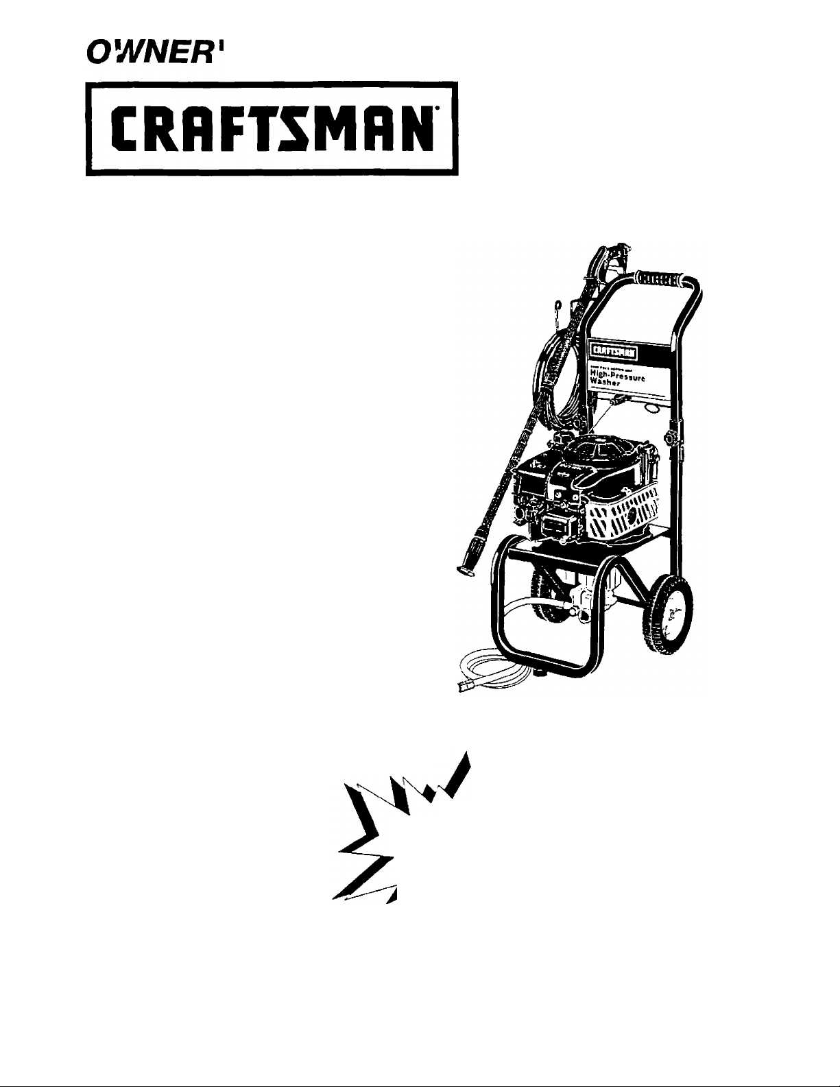
6.0 Horsepower
2400 PSI 2.4 GPM
High Pressure Washer
Model No:
919.679240
WARNING: Before using this
product, read this manual
and follow all Safety Rules
and Operating instructions.
MGP-879240 3/11/M
• Safety
• Assembly
PRESSURE WASHER /
CUSTOMER
HELPLINE
1-800-245-5873
• Operation
• Maintenance
• Parts List
• Français
Sold by Sears Canada, Inc., Toronto, Ont. M5B2B8
Page 2

TABLE OF CONTENTS
Warranty
Safety Guidelines
Assembly
Operation...................................................7-10
Product Specifications
Maintenance............................................11-13
.........................................................
........................................
.....................................................
.................................
FULL ONE YEAR WARRANTY ON CRAFTSMAN HIGH PRESSURE WASHER
For one year from the date of purchase, when this Craftsman High Pressure Washer is main
tained and operated according to the instructions in the owner’s manual, Sears will repair, free of
charge, any defect in material and workmanship.
3-5
5-7
11
2
Service and Adjustments
Storage........................................................14
Troubleshooting...........................................15
Parts.......................................................16-27
EPA Codes
Français
How to Order Parts
............................................
.................................................
.......................
....................
13-14
28-29
32-45
Back Cover
If your Craftsman Pressure Washer is used for commençai or rental purposes, this warranty
applies only for 90 days from the date of purchase.
FULL TWO YEAR WARRANTY ON CRAFTSMAN ENGINE
For two years from the date of purchase, when this Craftsman engine is maintained and operated
according to the instructions in the owner’s manual. Sears will repair, free of charge, any defect in
material and workmanship.
If your Craftsman engine is used for commençai or rental purposes, this warranty applies only for
90 days from the date of purchase. This warranty does not cover expendable Items such as
spark plugs and air filters, which become worn during normal use.
Repairs necessary because of operator abuse or negligence, including damage resulting from no
water being supplied to pump or failure to maintain the equipment according to the instructions
contained in the owner’s manual, are not covered under warranty.
WARRANTY SERVICE IS AVAILABLE BY RETURNING THE HIGH PRESSURE WASHER TO THE
NEAREST SEARS SERVICE CENTER THROUGHOUT THE UNITED STATES. This warranty gives
you specific legal rights and you may also have other rights, which vary from state to state.
Sears Canada, Inc., Toronto, Ont. M5B2B8
Page 3
SAFETY GUIDELINES - DEFINITIONS
This manual contains information that is important for you to know and understand. This information relates to protecting
YOUR SAFETY and PREVENTING EQUIPMENT PROBLEMS. To help you recognize this information, we use the symbols
below. Please read the manual and pay attention to these sections. SAVE THESE DEFINITIONS/INSTRUCTIONS.
A WARNING indicates a potentially hazardous
situation which, if not avoided, could result in
death or serious iniurv.
A CAUTION indicates a potentially hazardous situation
A DANGER indicates an imminently hazardous
situation which, if not avoided, wM! result in
which, if not avoided, mav result in minor or moderate
iniurv.
death or serious iniurv.
I0!it97
IMPORTANT SAFETY INSTRUCTIONS
AWARNING
Improper operation or maintenance of this product could result in serious injury and property damage. Read and understand all
warnings and operating instructions before using.
HAZARD
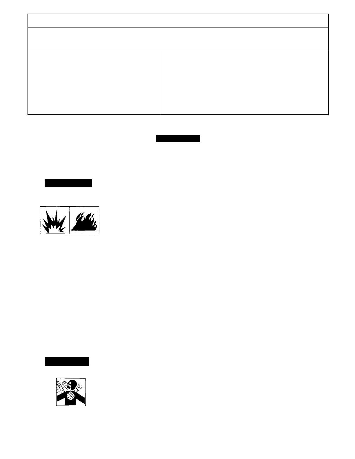
A DANGER
RISK OF EXPLOSION
OR FIRE
WHAT CAN HAPPEN
Spilled gasoline and its vapors can
become ignited from cigarette
sparks, electrical arcing, exhaust
gases, and hot engine components
such as the muffler.
Heat will expand fuel in the tank
which could result in spillage and
possible fire explosion.
Operating the pressure washer in an
explosive environment could result
in a fire.
Materials placed against or near the
pressure washer can interfere with
its proper ventilation features
causing overheating and possible
ignition of the materials.
Improperly stored fuel could lead to
accidental ignition. Fuel improperly
secured could get into the hands of
children or other unqualified persons.
HOWTO PREVENT IT
Shut off engine and allow it to cool
before adding fuel to the tank.
Use care in filling tank to avoid
spilling fuel. Move pressure washer
away from fueling area before
starting engine.
Keep maximum fuel level V2 below
top of tank to allow for expansion.
Operate and fuel equipment in well
ventilated areas free from obstruc
tions. Equip areas with fire
extinguishers suitable for gasoline
fires.
Never operate pressure washer in an
area containing dry brush or weeds.
Store fuel in container approved for
gasoline, in a secure location away
from work area.
Adanger
RISK TO BREATHING
Breathing exhaust fumes will cause
serious injury or death.
Some cleaning fluids contain sub
stances which could cause injury to
skin, eyes, or lungs.
Operate pressure washer in a well
ventilated area. Avoid enclosed
areas such as garages, basements,
etc.
Never operate unit in a location
occupied by humans or animals.
Use only cleaning fluids specifically
recommended for high pressure
washers. Follow manufacturers
recommendations.
Page 4

IMPORTANT SAFETY INSTRUCTIONS (cont’d)
HAZARD WHAT CAN HAPPEN
HOW TO PREVENT IT
AWARNING
RISK OF UNSAFE
OPERATION
Awarning
RISK OF INJURY FROM
SPRAY
Unsafe operation of your pressure
washer could lead to serious injury-'
or death to you or others.
The spray gun/wand is a powerful
cleaning tool that could look like a
toy to a child.
Reactive force of spray will cause
gun/wand to move, and could
cause the operator to slip or fall, or
misdirect the spray. Improper
control of gun/wand can result in
iniuries to self and others.
High velocity' fluid spray can cause
objects to break, propelling particles
at high speed.
Light or unsecured objects can become
hazardous projectiles.
Become familiar with the operation
and controls of the pressure washer.
Keep children away from the
pressure washer at all times.
Never defeat the safety features of
this product.
Do not operate machine with missing,
broken, or unauthorized parts.
Never leave wand unattended while
unit is running.
Keep work area free of obstacles.
Stand on a stable surface and grip
gun/wand firmly. Expect the gun to
kick when triggered.
Always wear ANSI approved Z87 safety
glasses. Wear protective clothing to
protect against accidental spraying.
Never point wand at, or spray people
or animals.
Always secure trigger lock when wand
is not in service to prevent accidental
operation.
Never permanently secure trigger in
pull back (open) position.
Awarning
RISK OF
ELECTRICAL
SHOCK
Awarning
RISK OF FLUID INJECTION
Awarning
RISK OF CHEMICAL BURN
I ili
Spray directed at electrical outlets or
switches, or objects connected to an
electrical circuit, could result in a
fatai electrical shock.
• Your Vi/asher operates at fluid
pressures and velocities high enough
to penetrate human and animal flesh,
which could result in amputation or
other serious injury. Leaks caused
by loose fittings or worn or damaged
hoses can result in injection injuries.
DO NOTTREAT FLUID INJECTION
AS A SIMPLE CUT! See a physician
immediately!
Relieve system pressure before
attempting maintenance or
disassembly of equipment.
Use of acids, toxic or corrosive
chemicals, poisons, insecticides, or
any kind of flammable solvent with
this product could result in serious
injury or death.
Unplug any electrically operated
product before attempting to clean it.
Direct spray away from electric outlets
and switches.
Never place hands in front of nozzle.
Direct spray away from self and
others.
Make sure hose and fittings are
tightened and in good condition.
Never hold onto the hose or fittings
during operation.
Do not allow hose to contact muffler.
Never attach or remove wand or hose
fittings while system is pressurized.
Use only hose and high pressure
accessories rated for 2400 PSI service
To relieve system pressure, shut off
engine, turn off water supply, and pull
gun trigger until water stops flowing.
Do not use acids, gasoline, kerosene,
or any other flammable materials in
this product. Use only household
detergents, cleaners and degreasers
recommended for use in pressure
washers.
Wear protective clothing to protect
eyes and skin from contact with
sprayed materials.
Page 5
IMPORTANT SAFETY INSTRUCTIONS (cont’d)
HAZARD
WHAT CAN HAPPEN
HOW TO PREVENT IT
Awarning
RISK OF HOT SURFACES
International
Symbols
The powerful spray from your pressure washer is capable of causing damage to fragile surfaces such as: wood,
glass, automobile paint, auto stripping and trim, and delicate objects such as flowers and shrubs. Before spraying,
check the item to be cleaned to assure yourself that it is robust enough to resist damage from the force of the spray.
Avoid the use of the concentrated spray stream except for very strong surfaces like concrete and steel.
Operating unit with water supply shut off without flow of water will result in equipment damage. You should never run
this pressure washer for more than 2 minutes without pulling the trigger to allow cool water to enter the pump and the
heated (recirculated) water to exit. Running the pressure washer with water supply shut off will void your warranty.
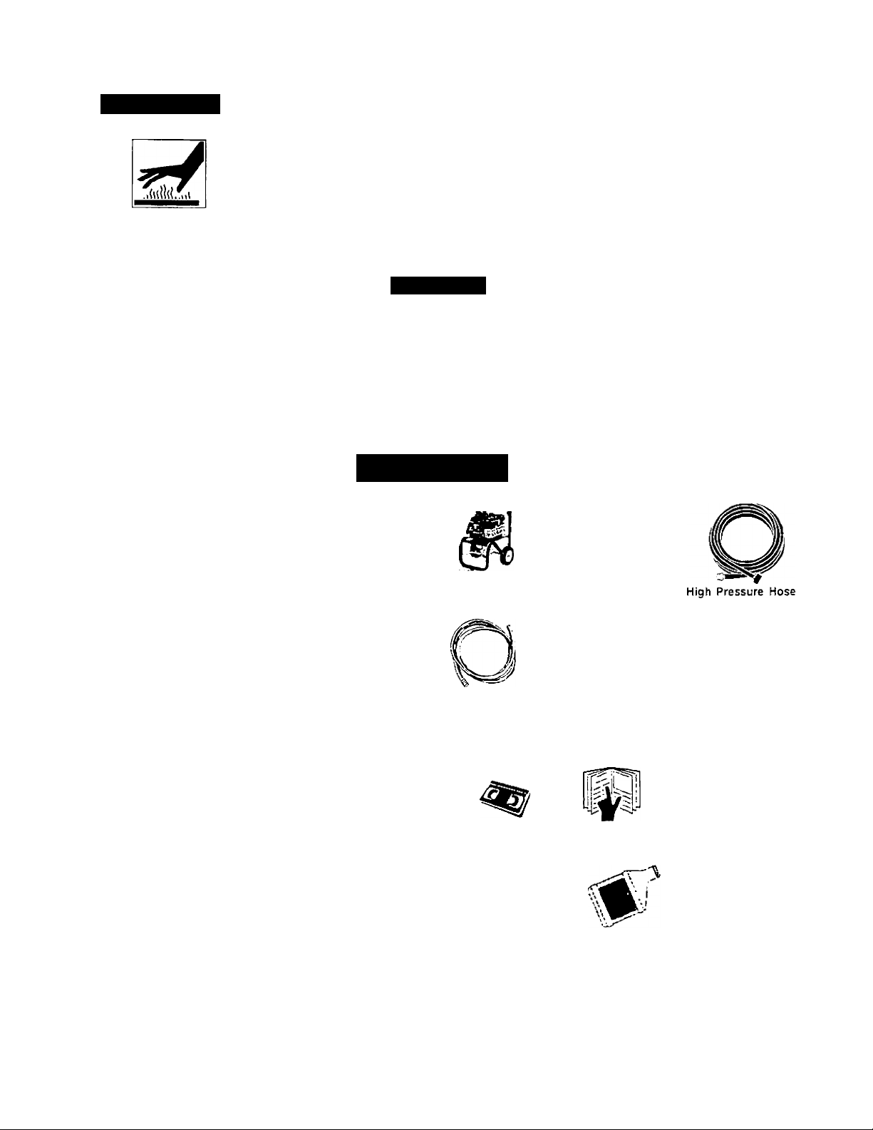
Contact with hot surfaces, such as
engines exhaust components, could
result in serious burn.
Safety Aled - Read
Owner's Manual
Q On OH (^) Stop
ACAUTION
During operation, touch only the control
surfaces of the pressure washer. Keep
children away from the pressure
washer at all times. They may not be
able to recognize the hazards of this
product.
Fuel
Shutoff
Fuel X Choke
i'
ASSEMBLY
Carton Contents
' Main Unit pressure washer with wheels
Handle
• High Pressure Hose
• Chemical Pickup Hose and Filter
• Gun
• Wand
Bag Containing
• Video Cassette
• Owner’s Manual
• Nozzle Cleaning Kit and Replacement 0-Rings
• Engine Oil
• Rubber Isolator and Mounting Hardware
• Handle Mounting Hardware
-
• «
r"»
a-
Main Unit Pressure Washer
with Wheels
Chemical Pickup Hose and Filter Gun and Wand
Handle
¡CCP-
a
Video Cassette Owner's Manual Nozzle Cleaning Kit
i
■»
Handle Mounting
Hardware
Engine Oil
Rubber Isolator and
Mounting Hardware
0
Replacement 0-Rings
Page 6
Tools Required for Assembly
Adjustable wrench
'en wrench
Remove Pressure Washer from Carton
• Open carton fronn the top. Locate and remove from
box the handle, gun, wand, videotape, and oil.
• Cut carton along dotted lines.
• Remove all carton inserts.
• Roll unit through opening in carton.
NOTE: The hose is located at the bottom of the box.
3. Mount the rubber isolator to the frame. To mount
isolator place threaded end of bolt through the
washer.
• Next with washer on bolt place threaded end of
bolt through the larger hole in bottom of the
rubber isolator.
• Place threaded portion of bolt through the same
hole location the wood plank was mounted to
on the pressure washer.
• Next place the tee nut over the threaded portion
of the bolt and use the Allen wrench provided to
tighten isolator to the frame.
TEE NUT
Preparing the Pressure Washer for First Use
Note: Included with your pressure washer is a video
cassette tape on how to prepare your unit for
operation. It is recommended you view this tape
before performing the next steps.
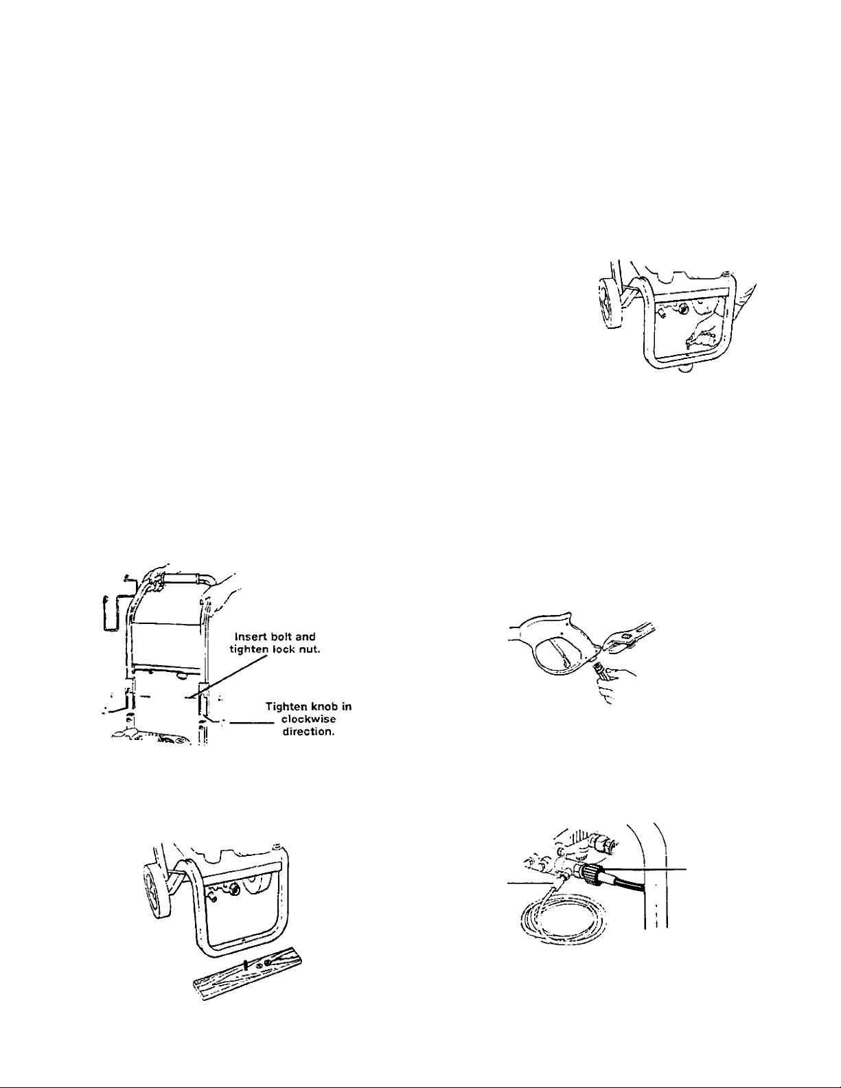
1. Insert handle onto frame.
« Insert knobs into the threaded slot in front of the
frame handle and tighten by turning in a clock
wise direction.
• Slide bolts into the slot in the side of the frame
handle and tighten the nuts by turning in a clock
wise direction.
PRESSURE
WASHER
FRAME
BOLT
--------
-ISOLATOR
S \
A WASHER
4. Connect wand extension to gun. To tighten, turn
knob in clockwise direction. Hand tighten.
------
5. Remove tie wrap off of high pressure hose.
Unwind high pressure hose and attach the
threaded end to the gun. Tighten with adjustable
wrench.
2. Using an adjustable wrench, remove nut from
bolt that attaches board to frame. Remove wood
plank from the frame of the unit. Discard bolt and
board.
6. Connect high pressure hose to outlet on
pressure washer and hand tighten firmly.
Connect chemical pickup hose to hose barb
on pump.
HIGH
PRESSURE
CHEMICAL
HOSE
HOSE
NOTE: Always keep hose away from engine muffler.
Page 7
7. Piace assembled gun and wane on pressure
v/asher bolder.
Lift the pull cord handle up and slide the core
to the left, sliding the cord into the wire loop
Next slide handle behind the wire bracket to
the left of the wire loop.
Engine recoil will pull the cord into its final
position.
Checklist
Before going any further please review the following:
• Be sure you have completed assembly instructions.
• Double check all fittings to be sure they are tight.
Place pul! cord into the wire bracket holder.
8.
Pull the cord under the wire bracket to the right
of the v«'ire loop.
OPERATION
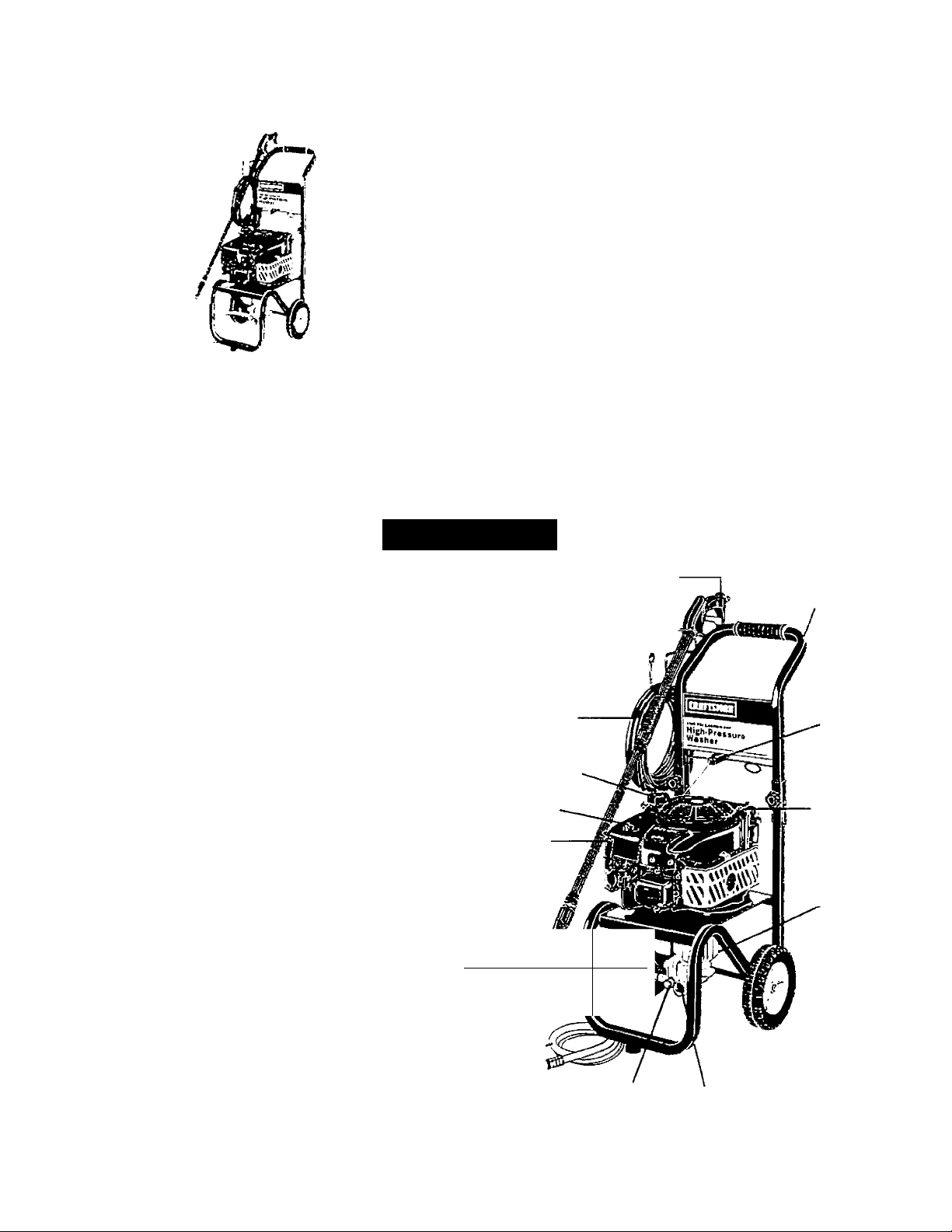
Know Your High Pressure Washer
, Read this Owner’s Manual and Safety Rules before
I operation of your High Pressure Washer Compare
I this illustration with our pressure washer to familiarize
I yourself with the location of various controls and adjusti ments. Save this manual for future reference.
PUMP- Develops high pressure.
PRESSURE REGULATOR- Allows you to adjust the
pressure of the outlet stream.
ENGINE RUN/STOP SWITCH- Sets engine in starting
mode for recoil starter — Stops running engine.
RECOIL STARTER- Used for starting the engine
manually.
IMPORTANT: Before any attempt to start your
pressure washer be sure to check engine oil (See
Operation under Engine Oil.)
SPRAY GUN
ASSEMBLY
HIGH PRESSURE
HOSE
GAS TANK/CAP
CHOKE
ENGINE
STOP/START
HANDLE
RECOIL
STARTER
OIL FILL
SPRAY GUN ASSEMBLY (Contains Gun and Wand)-
Controls the application of water onto cleaning surface
with trigger device.
OIL FILL- Port where engine oil is poured
GAS TANK/CAP- Cap is removed and unleaded
gasoline is poured.
CHEMICAL INJECTION TUBE AND FILTER- Mixes
water and detergent in outlet water flow.
HIGH PRESSURE OUTLET- Connection for high
ressure hose.
CHOKE- Lever used for starting unit.
PRESSURE 1
HbLiULAIuk 1
CHEMICAL
INJECTOR
TUBE & FILTER
^ (1
PRESSURE
OUTLET
y
HIGH
PUMP
II^
WATER INLET
CONNECTION
Page 8
A WARNING: Read Owner's Manual. Do not attempt
to operate equipment until you have read Owners
Manual for Safety, Operation, and Maintenance
Instructions.
Note: Included with your unit is a video cassette that
demonstrates how to operate your pressure washer.
If you have a video cassette recorder you should to
view the video before operation.
A WARNING: Never adjust spray pattern when
spraying. Never put hands in front of spray nozzle to
adjust spray pattern you could be injured.
Stopping Your Pressure Washer
A CAUTION: Do not run pump without the water
supply connected and turned on. Failure to do so
will result in pump damage.
Move throttle control to the stop position to turn
pressure washer off.
Before Starting The Engine
To operate the engine you will need to do the following.
Note: Your pressure washer pump is a sealed pump,
you should never have to add or change the oil.
A CAUTION: Always check engine oil level before
every start. Running engine low of oil or out of oil
could result in serious damage.
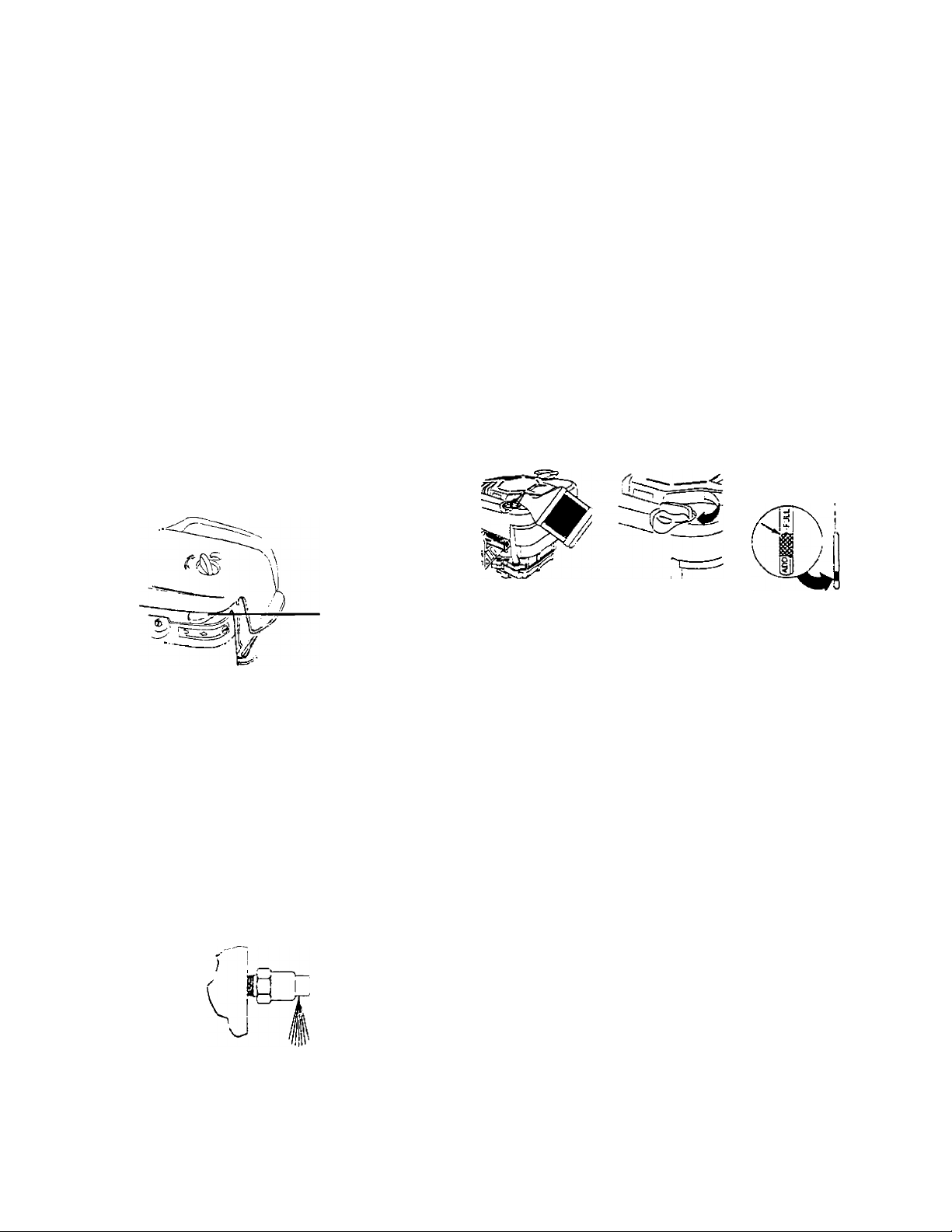
Engine Oil
Your unit has been shipped without oil in the engine. A
bottle of SAE 30 weight oil is included in the carton.
Remove oil dip stick located on top of the engine. Oil
capacity is about 20 ounces of oil. The oil dip stick is
clearly marked with a line that tells you when unit has
enough oil. To check oil, place dipstick into oil fill.
Tighten dipstick then remove. Do not fill above this
point. Pour slowly.
THROTTLE
CONTROL
Simply shutting OFF engine will not release pressure
in the system. After engine has stopped, squeeze
the trigger on the spray gun for about 3 seconds to
relieve pressure. Spray stream will decrease in
length.
IMPORTANT: This unit is equipped with a thermal relief
valve. If unit is allowed to run for several minutes
without pressing the trigger on the spray gun, several
drops of water may be released through this valve to
cool the unit. This small amount of water will drip from
the bottom of the pump.
NOTE: When adding oil to the engine crankcase, use a
high quality detergent oil classified “For Service SF, SG,
SH”, rated SAE 30 weight. Use no special additives.
Select the oil’s viscosity grade according to your
expected operating temperatures.
colder <
--------------------
40°F
-----------------
> warmer
Synthetic 5W-30 I SAE 30
Although multi-viscosity oils (5W30, 10W30, etc.)
improve starting in cold weather, these multi-viscosity
oils will result in increased oil consumption when used
above 40°F. Check your engine oil level more frequently
to avoid possible damage from running low on oil. Oil
sump capacity is 20 ounces.
Gasoline
Your pressure washer engine is 4 cycle. Use unleaded
fuel only.
A CAUTION: Do not overfill the fuel tank. Always
allow room for fuel expansion.
A WARNING: Never fill fuel tank indoors. To avoid
explosion and injury, never fill fuel tank when
engine is running or hot. Do not smoke or have
open flame when filling fuel tank.
Page 9
Use clean, fresh, regular unleaded gasoline with a
minimum of 85 octane. Do not mix oil with gasoline.
'f unleaded fuel is unavailable leaded fuel may be used.
IMPORTANT: It is important to prevent gum deposits
from forming in essential fuel system parts such as the
carburetor, fuel filter, hose or tank during storage. Also,
experience indicates that alcohol-blended fuels (called
gasohol or using ethanol or methanol) can attract
moisture which leads to separation and formation of
acids during storage. Acidic gas can damage the fuel
system of an engine while in storage. To avoid engine
problems, the fuel system should be emptied before
storage of 30 days or longer. Never use engine or
carburetor cleaner products in the fuel tank or perma
nent damage may occur.
A CAUTION: Never start pressure washer without
water source turned on and connected to
pressure washer. Failure to do so will cause
pump damage.
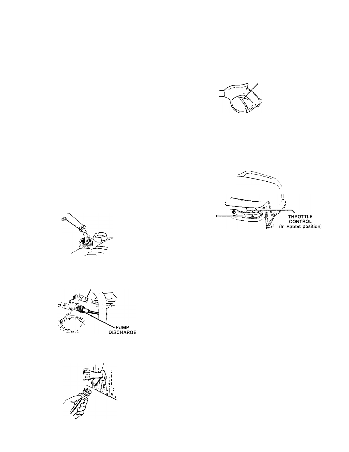
To Start Your Pressure Washer
Squeeze trigger on pressure washer wand to relieve
air pressure caused by turning on the water. Water
will spew out of the gun in a thin stream. This will
make it easier to start the engine.
Engage the safety latch on the spray gun. This locks
the trigger in place and keeps you from accidentally
spraying a high pressure stream.
SAFETY
LATCH
On the engine there is a choke/run lever. Place lever
to the choke position.
On the engine there is a throttle control lever. Place
throttle to the rabbit position. Always start engine
with throttle in the rabbit (high speed) position.
• Remove gas cap.
• Add unleaded gasoline, slowly, to fuel tank.
• Do not overfill.
Connect garden hose to the water inlet on the
pressure washer. Tighten by turning counterclock
wise.
PUMP
INLET
Connect high pressure hose to discharge on pump.
’ Connect the garden hose to the water spout and turn
water supply on.
CHOKE
• Grasp the starter grip and pull slowly until resistance
is felt, then pull firmly to start engine.
NOTE: If engine does not start right away, squeeze the
trigger on the gun to relieve air pressure caused by
turning on the water. Water will spew out of the gun in a
thin stream. This will make it easier to pull start the
engine. If more than five pulls, place choke lever back
to run position.
• When engine starts, gradually move choke lever to
RUN position.
• For hot engine restarts, make sure throttle is in the
rabbit (high speed) position and the choke lever is in
the RUN position.
• Grasp the starter grip and pull slowly until resistance
is felt, then pull firmly to start engine.
Page 10

How To Use Your Pressure Washer
Using Soaps/Chemicals
On the end of your spray gun is a nozzle that you can
slide forward and backward and that you can also
■ist from side to side. With the adjustable nozzle you
1 adjust the spray pattern to either high pressure
or low pressure. You can also adjust the spray so it is
concentrated in a stream pattern or expanded into a
fan pattern.
Slide the nozzle in aforward position to draw
cherfiical and achieve low pressure. Pull nozzle back
for high pressure.
HIGH PRESSURE LOW PRESSURE
To adjust your spray pattern twist the nozzle
clockwise for fan spray or counterclockwise for
stream: spray.
FAN SPRAY
STREAM SPRAY
For most effective cleaning, keep spray nozzle
between 8 and 24 inches from cleaning surface.
IMPORTANT: If you get spray nozzle too close,
especially on high pressure, you may damage the
surface you are cleaning.
•
• The pressure control knob is located on the pump.
You can increase the pressure by turning the knob
clockwise or decrease the pressure by turning the
knob counterclockwise.
IMPORTANT; Use soaps and chemicals that are
designed specifically for use with pressure washers.
To apply soaps/chemicals follow these steps:
• Prepare the soap/chemical as required by your job.
• Insert soap/chemical line into your container (soap/
chemicals and container not included).
CHEMICAL
HOSE
Slide the adjustable nozzle forward to low pressure
mode. Soap/chemicals cannot be applied with nozzle
in high pressure position.
Review the use of the adjustable nozzle.
Connect garden hose to water inlet (see “To Start
Your Pressure Washer" on page 9). Check that high
pressure hose is connected to spray gun and pump
{see Assembly), and start engine.
Apply soap/chemicals to dry surface, starting from
the bottom and working up.
Allow the soap/chemicals to soak in between 3-5
minutes before washing and rinsing.
When rinsing on high pressure, start at lower portion
of area to be washed and work upward, using long,
even, overlapping strokes.
NOTE: Your pressure washer is equipped with a
chemical injector adjustment knob. With the knob
fully opened you will get a maximum chemical draw.
With knob fully closed you will get no chemical draw.
Turn knob in counterclockwise direction to achieve
more chemical draw and clockwise for less chemical
draw.
NOTE: This unit is set at its maximum pressure at the
tory. Do not attempt to adjust the pressure higher
L, lan this factory setting.
10
Page 11

MAINTENANCE
CUSTOMER RESPONSIBILITIES TABLE
MAINTENANCE TASK
Before each use
hours or yearly
PRESSURE WASHER
Every 25
Check/clean inlet screen.
X
Check high pressure hose. X
Check soap and chemical hose and filter
X
Check gun and wand for leaks. X
Purge pump of air and contaminants
X
ENGINE
Check oil level
X
Change engine oil
Clean air cleaner and precieaner
X
Clean/replace spark plug
Clean engine muffler & finger guard X
Prepare for storage
Prepare unit for storage if it is to remain idle for longer than 30 days.
Every 50
hours or yearly
X
Every 100
hours or yearly
I
X
Product Specifications
Pressure Washer Specifications
Pressure
Flow Rate
Cleaning Units (psi x GPM)
Engine Specifications
RPM
Rated Horsepower
Spark Plug Gap
Gasoline Capacity
Oil (22 oz. capacity)
2400
2.4 GPM
5760
3600
.030” (0.76mm)
1.5 quarts
SAE 30 weight
6.0
General Recommendations
The warranty of the high pressure washer does not
cover items that have been subjected to operator
abuse or negligence. To receive full value from the
warranty, operator must maintain high pressure
washer as instructed in this manual.
Some adjustments will need to be made periodically to
maintain your high pressure washer.
Once a year you should clean or replace the sparkplug,
and clean or replace the air filter, and thoroughly check
the gun and wand assembly for wear. A clean spark
plug and clean air filter assure proper fuel-air mixture
and help your engine run better and last longer.
Your pressure washer pump is a sealed pump; you
should never have to add or change the oil.
NOTE: Over time the o-rings in the gun assembly
become worn. Attached to your owners manual is a
replacement o-ring and split backup ring.
O-ring
Split Backup
Ring
11
Page 12

Pressure Washer Maintenance Changing Engine Oi
Check and Clean Inlet Screen: Examine inlet screen
pump inlet fitting. Clean if clogged; replace if torn.
^neck High Pressure Hose: High pressure hose can
develop leaks from wear, kinking, abuse. Inspect hose
each time before use. Check for cuts, leaks, abrasions
or bulging of cover, and damage or movement of
couplings. If any of these conditions exist, replace hose
immediately.
Check Ghemical/Soap Hose: Examine the chemical/
soap hose and clean if clogged. Hose should fit tightly
on pump fitting. Check for leaks and tears. Replace
filter or hose if either is damaged.
Check Gun and Wand: Examine hose connection to
gun making sure it is secure. Test trigger by pressing it
and making sure it springs back into place when you
release it.
Pump Maintenance (Changing Pump Oil)
Your pressure washer pump is a sealed pump, you
should never have to change oil.
Purge Pump of Air and Contaminants
• Change oil while engine is still warm. Preferably
drain oil from top of engine as illustrated below.
Drain oil with air cleaner side up. Oil can be drained
from engine bottom if necessary.
IMPORTANT: Before tipping engine or equipment to
drain oil, drain fuel from tank by running engine until
fuel tank is empty.
DRAIN HOLE
To drain oil from bottom of engine, remove drain
plug as illustrated below. Allow oil to drain and
replace drain plug. Remove dipstick and refill with
new oil of recommended grade. Start and run engine
at idle for 30 seconds.
OIL DRAIN
To remove the air from the pump, follow these steps;
Set up the pressure washer as described in
assembly section and connect the water supply.
• Remove the wand extension from the spray gun.
• Pull the trigger on the gun and hold.
To remove the contaminants from the pump, follow
these steps:
•
• Set up the pressure washer as described in
ASSEMBLY section, connect the water supply.
• Remove the wand extension from the spray gun.
• Start the engine according to instructions in the
OPERATION section.
• Pull the trigger on the gun and hold.
• When the water supply is steady and constant,
disengage trigger and refasten the wand extension.
Engine Maintenance
Check Oil Level
• Oil level should be checked prior to each use
or at least every 5 hours of operation. To check oil
see Engine Oil on page 8.
Stop engine. Wait 30 seconds and re-check oil level.
If required, add oil to bring level to FULL mark on
dipstick.
Check Engine — Finger Guard/Muffler
• Do not clean engine with a forceful spray of
water because water could contaminate fuel system.
With a brush or cloth, clean any debris from finger
guard after every use to prevent engine damage
caused by overheating.
■ CLEAN
* Before running engine, clean muffler area to
remove all grass and combustible debris.
12
CLEAN
CLEAN
Page 13

Clean Pre-Cleaner and Air Cleaner Cartridge
Your engine is equipped vi'itii an ova: dual element
air cleaner: the two elements include a foam pre-cleaner
,nd an air cleaner cartridge.
NOTE; Do not use petroleum solvents, e.g., kerosene,
which will cause the cartridge to deteriorate. Do not use
pressurized air to clean cartridge. Pressurized air can
damage the cartridge.
• To remove the air cleaner element, loosen two cover
screw's and lift cover. Carefully remove foam pre
cleaner and air cleaner cartridge.
‘ To clean pre-cleaner and air cleaner cartridge, wash
in liquid detergent and water. Allow to dr^'
thoroughly before using. Do not oil the precleaner or
cartridge Replace if ver^' diny or damiaged.
' Aftef cleaning the pre-cleaner and air cleaner
cartridge, replace pre-cleane- on air cleaner
cartridge.
• Instar air cleaner- assembly (pre-cleaner and
cartridge) in base. Then install cover on air cleaner
and tighten screws securely tc base.
2 SCREW'S
PRE-CLEANER
tOVER
CARTRIDGE
Clean and Replace Spark Plug
Change the spark plug every 100 hours of operation or
once each year, whichever comes first. This w'ill help
your engine to start easier and run better.
SERVICE AND ADJUSTMENTS
Carburetor
The carburetor of your high pressure w'asher is pre-set
at the factor^'. The carburetor should not be tampered
with. If your pressure washer is used at an altitude in
excess of 5000 feet consult with your nearest Sears
Service Center regarding high altitude set changes.
A CAUTION: Engine speed was properly adjusted at
the factory and should require no additional adjust
ment. Do not attempt to change engine speed. If
you believe the engine is running too fast or too
slow, take your pressure to a Sears Authorized Ser
vice Center for repair and adjustment.
A WARNING: High engine speeds are dangerous and
increase the risk of personal injury or damage to
equipment.
A CAUTION: Low engine speeds impose a heavy
load on the engine and could shorten engine
life.
Nozzle Cleaning
If the nozzle becomes clogged with foreign materials,
such as dirt, excessive pressure may develop. If the
nozzle becomes partially clogged or restricted, the
pump pressure will pulsate. Clean the nozzle immedi
ately using the nozzle kit supplied and the following
instructions.
1. Shut off the pressure washer and turn off the water
supply.
2. Disconnect spark plug wire.
Page 14

Pull trigger on gun handle to relieve any water
pressure.
Disconnect the wand from the gun.
Remove nozzle from the the end of the wand with
the 2mm Allen wrench provided.
Clean the nozzle using the nozzle cleaner provided
6.
or a straightened paper clip. Insert into the nozzle
end and work back and forth until obstructions is
removed.
7. Direct water supply into nozzle end to backflush
loosened particles for 30 seconds.
<P
8. Reassemble the nozzle to the wand Tighten
securely to prevent leaks.
9. Reconnect wand to gun and turn on water suppply.
10. Start pressure washer and place wand into high
pressure setting to test.
STORAGE
Preparing Pressure Washer for Storage
NOTE: If you do not plan to use your unit for 30 days or
more, unit should be prepared for storage.
IMPORTANT: It is important to prevent gum deposits
from forming in essential fuel system parts such as the
■rburetor, fuel filter, hose or tank during storage. Also,
experience indicates that alcohol-blended fuels (called
gasohol or using ethanol or methanol) can attract
moisture which leads to separation and formation of
acids during storage. Acidic gas can damage the fuel
system of an engine while in storage. To avoid engine
problems, the fuel system should be emptied before
storage of 30 days or longer. Never use engine or
carburetor cleaner products in the fuel tank or perma
nent damage may occur.
Engine Preparation
• First add a fuel stabilizer to the fuel tank.
• Run pressure washer for a full 5 minutes to allow fuel
stabilizer to enter the fuel system.
• Next shut off engine and disconnect the water
supply.
• Disconnect the spark plug wire and remove the spark
plug.
•
• Add one teaspoon of oil through the spark plug
hole.
• Place rag over spark plug hole and pull the recoil a
few times to lubricate the combustion chamber.
• Replace the spark plug, but do not connect the spark
plug wire.
A CAUTION: While preparing the engine make sure
water supply is turned on and flowing to the unit.
NEVER run unit without water supply running
through pump. Failure to do so will cause pump
damage.
Pump Preparation
This pressure washer should be stored in such a way
to protect it from freezing. Do not store this unit
outdoors or in an area where temperatures will fall
below 32° F. This can cause extensive damage to this
unit.
If unit has to be stored under freezing conditions a
non-toxic R.V. anti-freeze should be put in the pump
according to steps below to protect from freezing.
Be sure engine switch is in "OFF" position and spark
plug wire has been removed from spark plug.
Pull the trigger on the spray gun to release the
pressure in the high pressure hose. Detach high
pressure hose and garden hose from the unit.
Pull the recoil on the engine 4 to 6 times to dis
charge remaining water in pump.
Tip the unit on the end with the water inlet fitting
pointing upward.
If unit will be stored where tempertures fall below
32°F, pour approximately 1/4 cup of non-toxic R.V.
anti-freeze down the fitting where the water hose
attaches to the pump.
Set unit upright and pull starter handle on engine 4
to 6 times to circulate anti-freeze in pump until anti
freeze is discharged from the pump.
14
Page 15

SYMPTOM
Engine won’t
start
TROUBLESHOOTING
CAUSE
1. Engine throttle is in "OFF" Position.
2. Choke lever has not been placed to
choke.
3. Pressure buildup after initial use.
-
SOLUTION
1. Slide throttle to "Run" position.
2. Slide choke lever to choke position.
3. Depress trigger gun.
Wqn’t Draw
Chemical
Pump running
normally but
pressure does
not achieve rated
values
Fluctuating
Pressure
1. Nozzle not in chemical draw position.
2. Chemical screen is obstructed.
3, Chemical screen not working.
4. Chemical injector orifice obstructed
or stuck.
1. Water supply restricted. 1. Check water supply and filter screen for
2. Nozzle is in low PSI position.
3. Nozzle incorrect or worn.
4. Pump sucking air.
5. Nozzle blocked.
1. Pump sucking air.
2. Garden hose inlet strainer clogged. 2. Clean. Check filter frequently.
3. Worn Seals or Packing.
4, Inadequate water supply.
5. Fouled or dirty inlet or discharge
valves.
6. Leaky discharge hose.
1. Push nozzle forward at end of wand.
2. Check chemical screen; clean if obstructed.
3. Make sure chemical screen is submerged in
chemical/water.
4. Check and clean.
blockage. Check hoses for blockage, kinks,
leaks, etc.
2. Pull nozzle at end of wand back to the high pressure
position.
3. Check and replace.
4. Check that hoses and fittings are airtight.
5. Clean nozzle.
1. Check that hoses and fittings are airtight. Purge air
from garden hose.
3. Check and replace.
4. Check hose for kinks.
5. Check flow available to pump. Check for
excessive heat, 145° F or above.
6. Clean inlet and discharge valve assemblies.
Replace if damaged.
Pressure drops
after period of
normal use
Pump noisy
Presence of
water in oil (oil
milky);
Water dripping
from pump
Oil Dripping
1. Nozzle clogged, partially obstructed.
2, Nozzle worn. 2. Clean or replace.
3. Valves worn, dirty or stuck.
4. Worn piston packing.
1. Water too hot.
2. Pump sucking air.
3. Valves dirty or worn. 3. Check, clean or replace.
4. Worn bearings. 4. Check and replace if necessary.
1. High humidity.
2. Piston packing and oil seal worn.
1. Fittings Loose.
2. 0-rings of piston guide or retainer 2. Check and replace.
worn.
3. Piston packing worn.
1. Oil seal worn
2. Loose drain plug or worn drain plug
o-rinq.
1. Check connection. Replace if cracked or
punctured.
3. Check and replace.
4. Check and replace.
1. Reduce temperature below 63° C or 145° F.
2. Check that hoses and fittings are airtight.
1. Change Oil.
2. Check and replace oil seals.
1. Tighten.
3. Check and replace.
1. Check and replace
2. Tighten drain plug or replace o-ring. Do not over torque.
15
Page 16

i J
CRAFTSMAN 2400 PSI HIGH PRESSUIRE WASHER 919.679240
PARTS
24
/ Ci f -0
REF NO. PART NUMBER DESCRIPTION
1
2
3
4
5
6
7
8
10
11
12
13
14
15
16
17
19
900
20
21
22
23
24
17715
0042
17628
17709
W137
16371
W131
17713
H140
17774
16467
17569
F064
F469
17712
17716
17367
PK16482
16829
F504W
F112
AL-650015
Handle
Knob - 5/16"
Gun
Tire Semi (7x1 3/4”)
Nut Pal 1/2"
Rubber Foot, Hollow
Tee Nut 5/160” x 3/4”
Frame
Hose, Chemical
Lance, Multi-Reg
Hose
Decal Craftsman
Screw - Hex 5/16" - 18 x 1 LG
Lock Nut 5/16"
Screw HHC, 5/16”
Decal Operation
Handle Grip
Engine (Refer to Engine Break
down (Model 120602-01350
Pump
Garden Hose Adapter 1/2”
3/8” Coupling
Washer
0-Ring Kit
PARTS NOT ILLUSTRATED
MGP-769010 Owners Manual
NCT001 Nozzle Cleaning Kit
FI 01 Screw, Hex-Engine to Pump
F196 Screw, Hex-Engine to Pump
16087 Nut Flanghead-Engine to Pump
F074 Washer Flat-Engine to Pump
16505 Thermal Relief Valve
ACCESSORIES
(Not Included with Pressure Washer)
E2)
919.76430
919.76431
919.76450
919.76451
919.76484
Floor/Siding Brush
Fixed Brush
25Ft. 3/8" high pressure hose
50Ft. 3/8" high pressure hose
Turbo nozzle
16
Page 17

PUMP PARTS
CRAFTSMAN 2400 PSI HIGH PRESSUIRE WASHER 919.679240
PUMP BREAKDOWN MODEL PK16482
F27
17
Page 18

PUMP PARTS
CRAFTSMAN 2400 PSI HIGH PRESSUIRE WASHER 919.679240 PUMP BREAKDOWN MODEL PK16482
. s/ -V 1 1 ^ W 1 >
,EF.
NO.
1 AR-1 322520
2 AR-1980300
2
й
5 AR-1080070 Pin
6 AR-1980220 Plate Sprinc
7
c
c
* о
L/ AR-1 080250 0-Ring
*2
c
' 6 AR-1 0801 90
1 7
18 AR-1980200
19 AR-1470210 0-Rlng 58
20 AR-880581
21
23 AR-1980310 Screw' 3 61
24
25
26 AR-1260162
27
28
30
О ■*
2
oo
>^4J
34
35
36
PART
NO.
AR-1980470 Grub Screv\'
AR-1 980640 Handle Insert 41
AR-1271070 Spring
AR-1080041
AR-1 080401 RiriQ
AR-1980210 Piston Guioe
AR-880830 0-Rinq
AR-740290
A.R-800560 0-Ring
AR-1271170 Ring
AR-1271160
AR-820510 O-Ring
AR-650530
AR-1980650 Pump Него
AR-960160 0-ring 3 65 AR-1980230
AR-1269050
AR-480480 O-Ring 1 68
AR-1250280
AR-1560520 Spring 1
AR-1460430 O-Ring
AR-1540170 Jet 1 73 AR-480560
AR-1080091 Spring
AR-394280
DESCRIPTION
Knob
Nut
Upper Pision
O-Ring
0-Rina 2 55
Lower Piston
Valve Seat
Plug
Washer
Plug
Complete Valve
Ball
QTY.
1
1
1
1
7
,
•
1
1
2
2
1
3 64 AR-1980450
1
*
1
1 74 AR-1560670 Knob
O-Ring
1
REF.
NO.
37
38 AR-1270130
40 AR-1980190
42 AR-1980180
43 AR-770130
44
45
46
47
48
49 AR-1980430
52
53 AR-180030
54 AR-1980160
56
57
59 AR-1980240
60 AR-850370
62
63 AR-1980340
66
70
71 AR-1560650 Hose Tail
72 AR-800560
75
PART
NO.
AR-1200690
AR-1342761
AR-1260440
AR-1980170
AR-1980410
AR-770090
AR-1980460
AR-1980290
AR-1980140
AR-1980150
AR-1980130 Rail
AR-1980250 Cage
AR-1980070
AR-1980440
AR-480671
AR-1980510
AR-1200430
AR-1560660
DESCRIPTION
O-Ring
Detergent Injector 1
Support Ring 3
Gasket
Piston Guide
O-Ring
Gasket
Ring
Seal
O-Ring 1
Housing
Spacer
Oil Plug
Screw 4
Spring
Piston
Ring
Rail
Screw 1
Wobble Plate
Hollow Shaft 1
O-Ring 1
Flange
Roller Bearing
Seal
El. Motor Flange
Screw
O-Ring 1
O-Ring
Ring
QTY.
1
О
vj
3
Q
3
3
3
■\
3
1
3
3
5
1
2
3
1
\
1
1
1
1
A=K!T 16739 B=KiT 16740
Valves
Pos. Qty.
12 6
Pistons
Pos. Qty.
55 3
2S 6
F=KIT 16737
Unloader Valve
Pos. Qty.
1
2
3
4
5
6
7
1
1
1
1
1
2
1
Pos. Qty.
8 1
9
1
10 1 17 1
11
1
12 1
13 1
14
1
Pos.
15
16
18
19
PARTS KITS
C=KIT 16742
Oil Seals Water Seals
Pos. Qty.
46 3
47 1 41
66 1 43 3
G=KIT16741
Chemical Injector
Qty.
1 30 1 57
2
1 73
1
18
D=KIT 16738
Pos. Qty.
40
3
3
44
3
45
3
49
3
H=KIT 16743
Pos. Qty. Pos.
71
1 58 2
72 1 59
1
65
74 1
75
1
Bearing
Qty.
1
3
1
Page 19

ENGINE PARTS
CRAFTSMAN 2400 PSI HIGH PRESSUIRE WASHER 919.679240
BRIGGS ENGINE MODEL «120602-01350-E2
I REF,
NO.
11
*: Included in Gasket Set-Part No, 692702.
A Included in Valve Overhaul Kit-Part No. 692705.
PART
NO.
1
692670 Cylinder Assembly 45 262679 Tappet-Valve 619
2
399269
3
*299819
5
692800
7
*A273240 Gasket-Cylinder Head
8
495786
9
*272481
10
94955
499675 Tube-Breather
13
95049
33
499642
34
499641
35
263149
40 93312
DESCRIPTION
Bushing
Seal-Oil
Head-Cylinder
Breather Assembiv
Gasket-Breather
Screw-Hex.
Screw-Hex.
Valve-Exhaust
Valve-Intake
Spring-Valve
Retainer-Valve Passage
Assemblies include all parts shown in frames.
REF.
NO.
122i«*»i692799 Spacer-Carburetor
155
189
238 263131 Cap-Valve
306
O U J
337
383 19374 Wrench-Spark Plug
529 281736 Grommet
584
585
PART
NO. DESCRIPTION
51>*>i692668 Gasket-Intake
225325 Plate-Cylinder Head
263108 Ball-Rocker Arm
225366 Shield-Cylinder
1 W %_)wi W W r 1
Pliirw5=;n;)rW
224328 Cover-Breather
Passage
*272238 Gasket-Breather
19
REF
NO.
1023
1026
1029
1034
• Included in Carburetor Kit-Part No. 692703
♦ Included in Carburetor Gasket Set-Part No. 692704.
PART
NO. DESCRIPTION
94744 Screw-Hex.
635 66538
718
230192
630
499756 Stud-Rocker Arm
866
*A498592 Seal-Valve
883 *A273348 Gasket-Exhaust
993
*A273346 Gasket-Plate
1019
693B6B
1022 *A273241
499624 Cover-Rocker
498597
225246
281621
Bool-Spark Plug
Pin-Locating
Label Kit
Gasket-Rocker Cover
Rod-Push
Arm-Rocker
Guide-Push Rod
Page 20

ENGINE PARTS
CRAFTSMAN 2400 PSI HIGH PRESSUIRE WASHER 919.679240
284
847
28
<z>
27
o
L
BRIGGS ENGINE MODEL #120602-01350-E2
24
616
REF. PART
NO. NO. DESCRIPTION
16 693291 Crankshaft
24 222696 Key-Flywheel
25 499627 Piston Assembly
(Standard)
-----------692788 Piston Assy. 692786 Ring Set
(.010" O.S.)
692789 Piston Assy.
(.020" O.S.)
692790 Piston Assy. 27 263190 Lock-Piston Pin
(.030” O.S.)
(Standard)
Note
----------
REF. PART
NO. NO. DESCRIPTION
26 499631 Ring Set
28 499423 Pin-Piston
29 499424 Rod-Connecting
32 94699 Screw-Connecting
116 *280393 Seal-O-Ring Assembly
(Standard)
-----------692785 Ring Set
(.010" O.S.)
(.020" O.S.)
692787 Ring Set
(.030" O.S.)
Rod
Note
----------
REF. PART
NO. NO. DESCRIPTION
116A *280966 Seal-O-Ring
146 94388 Key-Timing
227 498772 Lever-Governor
284 94511 Screw-Shoulder
404 67072 Washer
523 499621 Dipstick
525 495265 Tube-Oil Fill
562 94852 Bolt-Governor Lever
592 231082 Nut-Hex.
615 94474 Retainer-Governor
616 263175 Crank-Governor
741 262598 Gear-Timing
847 498715 Dipstick/Tube
Included in Gasket Set-Part No. 692702.
Included in Valve Overhaul Kit-Part No. 692705.
Assemblies include all parts shown in frames.
• Included in Carburetor Kit-Part No. 692703
♦ Included in Carburetor Gasket Set-Part No. 692704.
20
Page 21

ENGINE PARTS
CRAFTSMAN 2400 PSI HIGH PRESSUIRE WASHER 919.679240 BRIGGS ENGINE MODEL «120602-01350-E2
REF. PART
NO. NO. DESCRIPTION
4 499619 Sump-Engine
12 *272198 Gasket-Crankcase
15 94880 Plug-Oil Drain
20 *399781 Seal-Oil
REF. PART
NO. NO. DESCRIPTION
258 94220 Screw-Hex.
-----------94612 Screw-Hex.
One Used in Hole
Nearest Breather.
Note
----------
258 ©
p^p PART
NO.' NO. DESCRIPTION
43 493737 Govemor/Oil Slinger
46 499749 Gear-Cam
* Included in Gasket Set-Part No. 692702.
A Included in Valve Overhaul Kit-Part No. 692705.
Assemblies include all parts shown in frames.
Included in Carburetor Kit-Part No. 692703
Included in Carburetor Gasket Set-Part No. 692704.
21
Page 22

ENGINE PARTS
CRAFTSMAN 2400 PSI HIGH PRESSUIRE WASHER 919.679240
BRIGGS ENGINE MODEL #120602-01350-E2
134
133
4
b
I'
104
%
975
137
355
RE.P
PART
NO.
104
108
117
122»».i692799 Spacer-Carburetor
124
125
NO.
51-*.i692668 Gasket-Intake
95
94098 Screw-Round Head
•231371
223471 Valve-Choke
497466 Jet-Main 133
95048
693864 Carburetor
DESCRIPTION
Pin-Float Hinge 130 224908
Screw-Hex.
REF.
PART
NO.
NO.
•
127
131 499682
398187
134
•398188
137
••280492
117
DESCRIPTION
Plug-Welch
(Sold in Kit Only)
Valve-Throttle
Shaft-Throttle
Float-Carburetor
Valve-Needle 975
(Includes Seat)
Gasket-Float Bowl
REF.
NO.
141 693866 Shaft-Choke
163^.^692667
355 •♦271716 Washer-Seal
637 ♦•693867
692 262715 Spring-Detent
987
355
©
PART
NO. DESCRIPTION
Gasket-Air Cleaner
Seal-Choke Shaft
493640 Bowl-Float
•♦2S0S66
Seat-Throttle Shaft
Included in Gasket Set-Part No. 692702.
Included in Valve Overhaul Kil-Part No. 692705.
Assemblies include all parts shown in frames.
Included in Carburetor Kit-Part No. 692703
Included in Carburetor Gasket Set-Part No. 692704
22
Page 23

ENGINE PARTS
CRAFTSMAN 2400 PSI HIGH PRESSUIRE WASHER 919.679240
969
968
202
BRIGGS ENGINE MODEL #120602-01350-E2
604
564^7
472
843
%
971
REF. PART
NO. NO. DESCRIPTtON
51>*«d692668 Gasket-Intake 529
1 22«*.j692799 Spacer-Carburetor 564
163*»♦692667 Gasket-Air Cleaner
202 263146 Link-Mechanical Gov. 620 693378 Bracket-Control 969 94872 Screw-Hex.
209 263038 Spring-Governor 621 396847 Switch-Stop Assy
231 691147 Screw-Hex.
472 693809 Choke Shaft Knob
REF.
NO.
PART
NO. DESCRIPTION
281299
693808
604
693807 Cover-Control Kit
843 272616 Sleeve-Lever
Grommet
Screw-Hex.
REF
NO.
PART
NO. DESCRIPTION
966 693863
967 491588 Filter-Air
968 281340 Cover-Air Cleaner
970 94118 Screw-Hex.
971 94873 Screw-Hex.
Base-A/C Primer
231
*■ Included in Gasket Sel-Part No. 692702.
A Included In Valve Overhaul Kit-Part No. 692705.
Assemblies include all parts shown in frames.
Included in Carburetor Kit-Part No. 692703
Included in Carburetor Gasket Set-Part No. 692704.
23
Page 24

< -*
ENGINE PARTS
CRAFTSMAN 2400 PSI HIGH PRESSUIRE WASHER 919.679240
BRIGGS ENGINE MODEL #120602-01350-E2
930
332
1005
363
REF.
NO.
304
332
PART
NO, DESCRIPTION
23 6S2693
37
224511 Guard-Flywheel 334
65
78
499676
Flywheel 333
94904
Screw-Hex. 356
94744
Screw-Hex.
Housing-Blower
94877
Nut-Flywheel
1036 LABEL KIT-EMISSION
REF.
NO.
363 19069
373
PART
NO. DESCRIPTION
802574
497833 Wire-Stop 930 692675 Guard-Rewind
Armature-Magneto 455 225121 Cup-Flywheel
94731 Screw-Hex.
Flywheel Puller 1005 261657 Fan-Flywheel
94908 Nut-Hex. 1036
REF.
NO.
851
PART
NO. DESCRIPTION
493880 Terminal-Cable
499343
Label Kit-Emission
* Included in Gasket Set-Part No. 692702.
A Included in Valve Overhaul KIt-Part No. 692705.
Assemblies include all parts shown in frames.
• Included in Carburetor Kit-Part No. 692703
♦ Included in Carburetor Gasket Set-Part No. 692704.
24
Page 25

ENGINE PARTS
CRAFTSMAN 2400 PSI HIGH PRESSUIRE WASHER 919.679240
300
883
346 <3T
BRIGGS ENGINE MODEL «120602-01350-E2
SOS'«»
832
836A
REF.
NO.
187
188
284
300
305
★ Included in Gasket Set-Part No. 692702.
A Included In Valve Oveitiaul Kit-Part No. 692705.
PART
NO.
298049 Line-Fuel
398540
94511
692275
94744
DESCRIPTION
Screw-Shoulder
Screw-Shoulder
Muffler-Exhaust
Screw-Hex.
Assemblies include all parts shown in frames.
REF.
NO.
601 93053 Clamp-Hose
PART
NO.
346 691140
670 280512 Spacer-Fuel Tank 957
832 498736
836 94786 Screw-Hex.
DESCRIPTION
Screw-Hex.
Guard-Muffler
• Included in Carburetor Kit-Part No. 692703
♦ Included in Carburetor Gasket Set-Part No. 692704.
25
REF.
NO.
836A 94874
PART
NO. DESCRIPTION
883 :*:A273348 Gasket-Exhaust
498697
972
499618
Screw-Hex.
Cap-Fuel Tank
Tank-Fuel
Page 26

<- 1
ENGINE PARTS
CRAFTSMAN 2400 PSI HIGH PRESSUIRE WASHER 919.679240
BRIGGS ENGINE MODEL #120602-01350-E2
REF.
NO.
5B 260399
★ Included in Gasket Set-Part No. 692702.
A Included in Valve Overhaul Kit-Part No. 692705.
PART
NO.
55
497440
56 263074
DESCRIPTION
Housing-Re\wind 60
Starter
Pulley-Starter
Rope-Starter
(Cut To Required 459
Length)
REF.
NO.
PART
NO.
281434
65 94904 Screw-Hex.
373 94908 Nut-Hex. 689 263073
456
281503
281505 Plate-Paul Friction
DESCRIPTION
Grip-Starter Rope
Retainer-Spring
Included in Carburetor Kit-Part No. 692703
Included in Carburetor Gasket Set-Part No. 692704.
REF.
NO.
PART
NO.
461
608
497680 Starter-Rewind
DESCRIPTION
94943 Screw-Shoulder
Spring-Friction
Assemblies include all parts shown in frames.
26
Page 27

ENGINE PARTS
CRAFTSMAN 2400 PSI HIGH PRESSUIRE WASHER 919.679240
BRIGGS ENGINE MODEL #120602-01350-E2
REF. PART
NO. NO, DESCRIPTION
3 *299819 Seal-Oil
7 *A273240 Gasket-Cylinder Head
9 *272481 Gasket-Breather
12 *272198 Gasket-Crankcase (Includes Seat)
20 *399781 Seal-Oil 137 »♦ЗЗОАЗЗ Gasket-Float Bowl
51«*>a692668 Gasket-Intake
104 »231371 Pin-Float Hinge
116 *280393 Seal-O-Ring 358 692702 Gasket Set
116A *280966 SeaFO-Ring
121 692703 Carburetor Kit
1 22»**a692799 Spacer-Carburetor
* Included in Gasket Set-Part No. 692702.
Д Included in Valve Overhaul KIt-Part No. 692705.
REF PART
NO. NO. DESCRIPTION
127 • Plug-Welch
(Sold in Kit Only)
134 »398188 Valve-Needle
163«*>&692667 Gasket-Air Cleaner
355 »♦271716 Washer-Seal
585 *272238 Gasket-Breather
Passage
Assemblies include all parts shown in frames.
REF. PART
NO. NO. DESCRIPTION
637 »♦693867 Seal- Choke Shaft
868 *A498592 Seal-Valve
883 *Д273348 Gasket-Exhaust
977 692704 Gasket Set-
Carburetor
987 »♦280566 Seal-Throttle Shaft
993 *Д273346 Gasket-Plate
1022 *Д273241 Gasket-Rocker Cover
1033 692705 Kit-Valve Overhaul
• Included in Carburetor Kit-Part No. 692703
♦ Included in Carburetor Gasket Set-Part No. 692704.
27
Page 28

Briggs & Stratton Corporation (B&S), the California Air Resources Board (CARB)
and the United States Environmental Protection Agency (U.S. EPA)
Emission Control System Warranty Statement (Owner's Defect Warranty Rights and Obligations)
le interest ot the environment, B&S engines that meet strict emis-
jn requirements are labeled, 'This engine conforms to 1995 -1998
California emission regulations for ULGE engines and U.S. EPA
Phase i regulations for small non-road engines."
EMISSION CONTROL WARRANTY COVERAGE IS APPLICABLE
TO CERTIFIED ENGINES PURCHASED IN CALIFORNIA IN 1995
AND THEREAFTER, WHICH ARE USED IN CALIFORNIA, AND
TO CERTIFIED MODEL YEAR 1997 AND LATER ENGINES
WHICH ARE PURCHASED AND USED ELSEWHERE IN THE
UNITED STATES.
California and United States Emission Control Defects Warranty Statement
CARB. U.S EPA and B&S are pleased to explain the Emission
Control System Warranty or your 1996 and later utility or lawn and
garden equipment (ULGE) engine. In California, new ULGE engines
produced on or afle' August 1, 1995 must be designed, built and
equiDped to meet the State's stringent anti-smog standards.» Elsewnere in the United States, new nor-road, spark-ignition engines
certified for model year 1997 and later, must meet similar standards
set forth by the U.S. EPA. B&S must warrant the emission control
system on your engine for the periods of time listed below, provided
there has been no abuse, neglect or improper maintenance of your
ULGE engine.
Your emission control system includes parts such as the carburetor,
air cleaner, ignition system, muffler and catalytic converter. Also
included may be connectors and other emission related assemblies
Where a warrantable condition exists, B&S will repair your ULGE
engine at no cost to you including diagnosis, parts and labor.
Briggs & Stratton Emission Control Detects Warranty Coverage
JlGE engines are warranted relative to emission control parts below. If any covered part on your engine is defective, the part will be
defects for a period of two years, subject to provisions set forth repaired or replaced by B&S.
Owner’s Warranty Responsibilities
As the ULGE engine owner, you are responsible for the performance
of the reouired maintenance listec in your Operator.fOwner ManuaL
B&S recommends that vou retain ail your receipts covering mai.ntenance on your ULGE engine, but B&S cannot deny warranty solely
for the lack of receipts or for your failure to ensure the performance of
all scheduled maintenance.
As the ULGE engine owner, you should however be aware that B&S
may deny you warranty coverage if your ULGE engine or a part has
failed due to abuse, neglect, improper maintenance or unapproved
modifications.
You are responsible for presenting your ULGE engine to an Autho
rized B&S Service Dealer as soon as a problem exists. The undis
puted warranty repairs should be completed in a reasonable amount
of time, not to exceed 30 days.
If you have any questions regarding your warranty rights and
responsibilities, you should contact a B&S Service Representative
at 1-414-259-5262.
The emission warranty is a defects warranty. Defects are judged on
normal engine performance. The warranty is not related to an in-use
emission test.
Briggs & Stratton Emission Control Defects Warranty Provisions
■ ’e following are specific provisions relative to your Emission Control Defects Warranty Coverage. It is in addition to the B&S engine warranty
non-regulated engines found in the Operator/Owner Manual.
Warranted Parts 3.
Coverage under this warranty extends only to the parts listed
below (the emission control systems parts) to the extent these
parts were present on the engine purchased,
a. Fuel Metering System
• Cold start enrichment system (soft choke)
• Carburetor and internal parts
• Fuel Pump
b Air Induction System
• Air cleaner
• Intake manifold
c. Ignition System
• Spark plug(s)
• Magneto ignition system
d. Catalyst System 5.
• Catalytic converter
• Exhaust manifold
• Air injection system or pulse valve
e. Miscellaneous Items Used in Above Systems
• Vacuum, temperature, position, time sensitive valves
and switches
• Connectors and assemblies
Length of Coverage
B&S warrants to the initial owner and each subsequent purchaser
that the Warranted Parts shall be free from defects in materials 6.
and workmanship which caused the failure of the Warranted
Parts for a period of two years from the date the engine is deliv
ered to a retail purchaser.
No Charge
Repair or replacement of any Warranted Part will be performed
at no charge to the owner, including diagnostic labor which leads
to the determination that a Warranted Part is defective, if the
diagnostic work is performed at an Authorized B&S Service
Dealer. For emissions warranty service contact your nearest
Authorized B&S Service Dealer as listed in the “Yellow Pages"
under "Engines, Gasoline," “Gasoline Engines,” “Lawn
Mowers," or similar category.
Claims and Coverage Exclusions
Warranty claims shall be filed in accordance with the provisions
of the B&S Engine Warranty Policy. Warranty coverage shall be
excluded for failures of Warranted Parts which are not original
B&S parts or because of abuse, neglect or improper mainte
nance as set forth in the B&S Engine Warranty Policy. B&S is not
liable to cover failures of Warranted Parts caused by the use of
add-on, non-original, or modified parts.
Maintenance
Any Warranted Part which is not scheduled for replacement as
required maintenance or which is scheduled only for regular
Inspection to the effect of “repair or replace as necessary” shall
be warranted as to defects for the warranty period. Any
Warranted Part which is scheduled for replacement as required
maintenance shall be warranted as to defects only for the period
of time up to the first scheduled replacement for that part. Any
replacement part that is equivalent in performance and durability
may be used in the performance of any maintenance or repairs.
The owner is responsible for the performance of all required
maintenance, as defined in the B&S Operator/Owner Manual
Consequential Coverage
Coverage hereunder shall extend to the failure of any engine
components caused by the failure of any Warranted Part still
under warranty.
28
Page 29

Snggs & Stratton welcomes warranty repair and apologizes
0 you for being inconvenienced. Any Authorized Service
Oealer may perform warranty repairs. Most warranty repairs
are handled routinely, but sometimes requests lor warranty
service may not be appropriate. For example, warranty would
not apply il engine damage occurred because of misuse, lack
of routine maintenance, shipping, handling, warehousing or
improper installation, Similarly, warranty is void if the serial
numb^ of the engine has been removed or the engine has
been altered or modified
If a customer differs with the decision of the Service-Dealer, an
investigation will be made to determine whether the warranty
applies. Ask the Service Dealer to submit all supporting facts to
his Distributor or the Factory for review. If the Distributor or the
Factory decides that the claim is justified, the customer will be
fully reimbursed for those items that are defective. To avoid
misunderstanding which might occur between the customer
and the Dealer, listed below are some of the causes of engine
failure that the warranty does not cover.
Improper maintenance;
The life of an engine depends upon the conditions under
which it operates, and the care it receives. Some applications,
such as tillers, pumps and rotary mowers, are very often used
in dusty or dirty conditions, which can cause what appears to
be premature wear. Such wear, when caused by dirt, dust,
spark plug cleaning grit, or other abrasive material that has
entered the engine because of improper maintenance, is not
covered by warranty.
This warranty covers engine related defective material
and/or workmanship only, and not replacement or refund
of the equipment to which the engine may be mounted.
Nor does the warranty extend to repairs required
because of:
4. Parts which are scored or broken because an engine was
operated with insufficient or contaminated lubricating oil.
or an incorrect grade of lubricating oil (check oil level daily
or after every 8 hours of operation. Refill when necessary
and change at recommended intervals.) Read "Owner’s
Manual.'
5. Repair or adjustment of associated parts or assemblies
such as clutches, transmissions, remote controls, etc.,
which are not manufactured by Briggs & Stratton.
6. Damage or wear to parts caused by dirt, which entered
the engine because of improper air cleaner maintenance,
re-assembly, or use of a non-original air cleaner element
or cartridge. (At recommended intervals, clean and re-oil
the Oil-Foam® element or the foam pre-cleaner, and
replace the cartridge.) Read "Owner’s Manual.”
7. Parts damaged by overspeeding, or overheating caused
by grass, debris, or dirt, which plugs or clogs the cooling
fins, or flywheel area, or damage caused by operating the
engine in a confined area without sufficient ventilation.
(Clean fins on the cylinder, cylinder head and flywheel at
recommended intervals.) Read “Owner's Manual.”
8. Engine or equipment parts broken by excessive vibration
caused by a loose engine mounting, loose cutter blades,
unbalanced blades or loose or unbalanced impellers,
improper attachment of equipment to engine crankshaft,
overspeeding or other abuse in operation,
9. A bent or broken crankshaft, caused by striking a solid
object with the cutter blade of a rotary lawn mower, or
excessive v-belt tightness.
10. Routine tune-up or adjustment of the engine.
11. Engine or engine component failure, i.e., combustion
chamber, valves, valve seats, valve guides, or burned
starter motor windings, caused by the use of alternate
fuels such as, liquified petroleum, natural gas. altered
gasolines, etc.
1. PROBLEMS CAUSED BY PARTS THAT ARE NOT
ORIGINAL BRIGGS & STRATTON PARTS.
2. Equipment controls or installations that prevent starting,
cause unsatisfactory engine performance, or shorten
engine life. (Contact equipment manufacturer.)
3. Leaking carburetors, clogged fuel pipes, sticking valves,
or other damage, caused by using contaminated or stale
fuel, (Use clean, fresh, lead-free gasoline and Briggs &
Stratton gasoline stabilizer. Part No. 5041.)
29
Page 30

CRAFTSMAN
MODEL NO.
919.679240
SERVICE
OWNER^S MANUAL
The model number of your Sears Air Compressor can be
found
on the maintenance label on the top of the shroud or on the
bar code label on the rear of the air tank.
SERVICE AND REPAIR PARTS
CALL 1-800-665-4455*
Keep this number handy should you require a service
call or need to order repair parts.
If ordering parts make sure you have the name, make
and model no. of the merchandise and the name and
number of the part you wish to order.
HOW TO ORDER
REPAIR PARTS
calling locally, please use one of the following numbers:
Regina-566-5124
Toronto-744-4900
Kitchener-894-7590
Vancouver
WHEN ORDERING REPAIR PARTS, ALWAYS GIVE THE
FOLLOWING INFORMATION:
PART NUMBER
MODEL NUMBER
All parts listed may be ordered from any Sears Service Center
and most Sears stores.
If the parts you need are not stocked locally, your order will be
electronically transmitted to a Sears Repair Parts Distribution
Center for handling.
Montreal-333-5740
Halifax -454-2444
Ottawa-738-4440
420-8211
• PART DESCRIPTION
• NAME OF ITEM
Sold By Sears Canada, Inc., Toronto, Ont. MSB 2B8
 Loading...