

Page 1
OWNER'S MANUAL
CRAFTSMAN
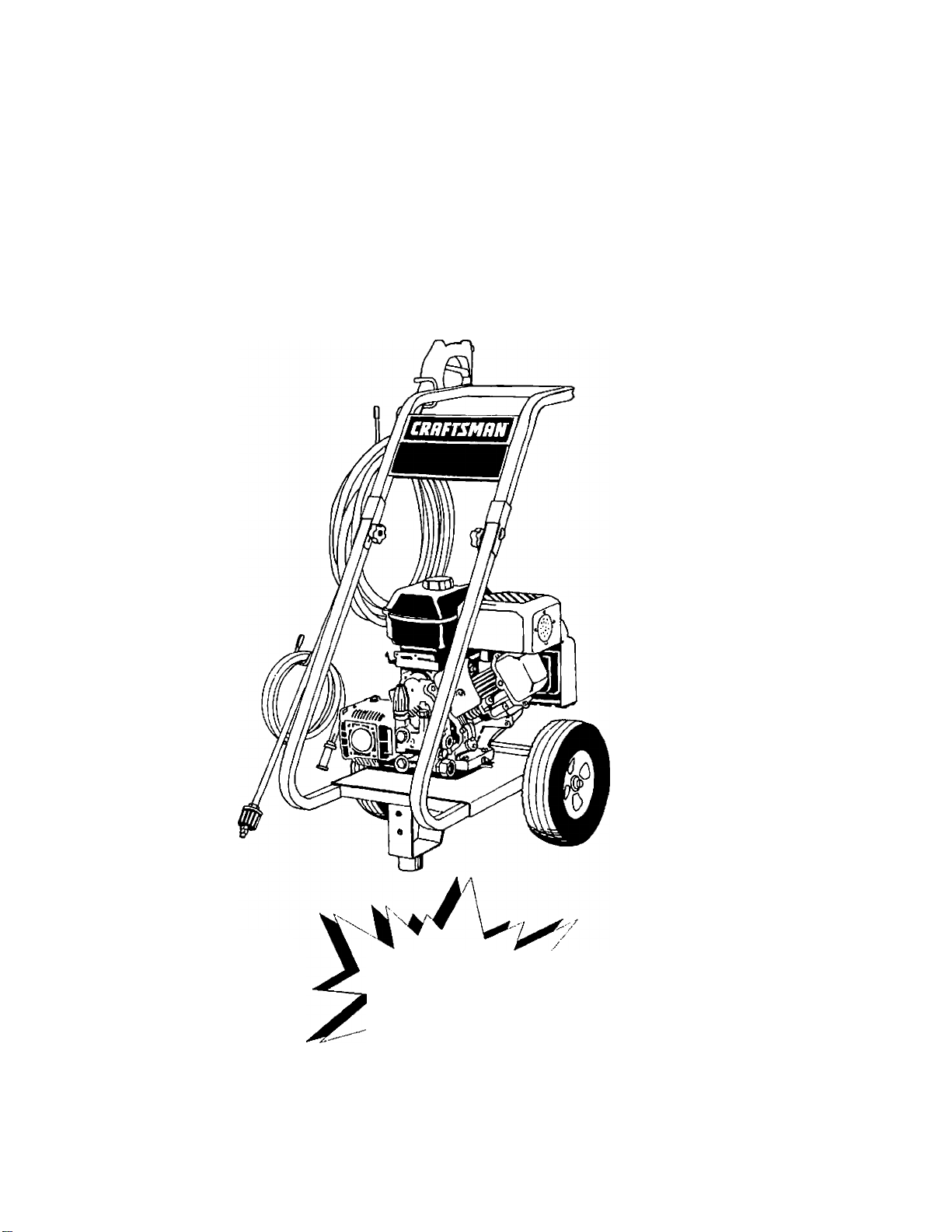
6.5 Horsepower 2500 PSI 2.7 GPIVI High Pressure Washer
Model No;
919.678250
WARNING: Before using this
product, read this manual
and follow all Safety Rules
and Operating Instructions.
Sears, Roebuck and Co., Hoffman Estates, IL 60179 U.S.A.
1S622 MGP-67B250A Rev. 4/B/S8
PRESSURE WASHER /
CUSTOMER
r HELPLINE
1-800-245-5873
• Safety
• Assembly
• Operation
• Maintenance
• Parts List i
• Français
Page 2

Page 3

TABLE OF CONTENTS
Warranty
Safety Guidelines
Assembly..................................
Operation..................................
Maintenance.............................
Service and Adjustments
...................................
....................
........
........
........
........
........
........
........
2
3-5
5-7
7-11
12-14
15
Storage ..........................
Troubleshooting............
Parts
...............................
EPA Codes
How to Order Parts
Español
....................
.......
..........................
LIMITED ONE YEAR WARRANTY ON CRAFTSMAN HIGH PRESSURE WASHER
For one year from the date of purchase, when this Craftsman High Pressure Washer is maintained
and operated according to the instructions in the owner’s manual, Sears will repair, free of charge,
any defect in materiai and workmanship.
If your Craftsman Pressure Washer is used for commericai or rental purposes, this warranty
appiies only for 90 days from the date of purchase.
.......................15
.......................16
.................17-28
................. 29-30
.......
Back Cover
................. 32-50
LIMITED ONE YEAR WARRANTY ON CRAFTSMAN ENGINE
Maintenance, replacement or repair of the emission control devices and systems may be per
formed by any nonroad engine repair estabiishment or individuai. However, to obtain no charge
repairs under the terms and provisions of Craftsman warranty statement, any service or emission
controi part repair or replacement must be performed by an factory authorized dealer.
For one year from the date of purchase, when this Craftsman engine is maintained and operated
according to the instructions in the owner’s manual. Sears will repair, free of charge, any defect in
materiai and workmanship.
If your Craftsman engine is used for commericai or rentai purposes, this warranty applies only for
90 days from the date of purchase. This warranty does not cover; Expendable items such as
spark plugs and air filters, which become worn during normal use.
Repairs necessary because of operator abuse or negligence, inciuding damage resuiting from no
water being supplied to pump or failure to maintain the equipment according to the instructions
contained in the owner’s manuai, are not covered under warranty.
WARRANTY SERViCE IS AVAILABLE BY RETURNING THE HIGH PRESSURE WASHER TO THE
NEAREST SEARS SERVICE CENTER/DEPARTMENT THROUGHOUT THE UNITED STATES.
This, warranty gives you specific legai rights and you may also have other rights, which vary from
state to state.
Sears, Roebuck and Co., D/817 WA, Hoffman Estates, IL 60179
Page 4

Page 5

SAFETY GUIDELINES - DEFINITIONS
This manual contains information that is important for you to know and understand. This information relates to protecting
YOUR SAFETY and PREVENTING EQUIPMENT PROBLEMS. To help you recognize this information, we use the symbols
below. Please read the manual and pay attention to these sections. SAVE THESE DEFINITIONS/INSTRUCTIONS.
A WARNING indicates a potentially hazardous
situation which, if not avoided, could result in
death or serious iniurv.
A CAUTION indicates a potentially hazardous situation
A DANGER indicates an imminently hazardous
situation which, if not avoided, win result in
death or serious iniurv.
which, if not avoided, mav result in minor or moderate
iniurv.
lo/s/gy
IMPORTANT SAFETY INSTRUCTIONS
AWARNING
Tiproper operation or maintenance of this product couid result in serious injury and property damage. Read
md understand ail warnings and operating instructions before using.
HAZARD
A DANGER
RISK OF EXPLOSION
OR FIRE
WHAT CAN HAPPEN HOW TO PREVENT IT
• Spilled gasoline and its vapors can
become ignited from cigarette
sparks, electrical arcing, exhaust
gases, and hot engine components
such as the muffler.
• Heat will expand fuel in the tank
which could result in spillage and
possible fire explosion.
Operating the pressure washer in an
explosive environment could result
in a fire.
Materials placed against or near the
pressure washer can interfere with
its proper ventilation features
causing overheating and possible
ignition of the materials.
Improperly stored fuel could lead to
accidental ignition. Fuel improperly
secured could get into the hands of
children or other unqualified persons.
Shut off engine and allow it to cool
before adding fuel to the tank.
Use care in filling tank to avoid
spilling fuel. Move pressure washer
away from fueling area before
starting engine.
Keep maximum fuel level Vi" below
top of tank to allow for expansion.
Operate and fuel equipment in well
ventilated areas free from obstruc
tions. Equip areas with fire
extinguishers suitable for gasoline
fires.
Never operate pressure washer in an
area containing dry brush or weeds.
• Store fuel in container approved for
gasoline, in a secure location away
from work area.
Adanger
RISK TO BREATHING
Breathing exhaust fumes will cause
serious injury or death.
• Some cleaning fluids contain sub
stances which could cause injury to
skin, eyes, or lungs.
Operate pressure washer in a well
ventilated area. Avoid enclosed areas
such as garages, basements ,etc.
Never operate unit in a location
occupied by humans or animals.
Use only cleaning fluids specifically
recommended for high pressure
washers. Follow manufacturers
recommendations.
Page 6

Page 7

IMPORTANT SAFETY INSTRUCTIONS (contad)
HAZARD
WHAT CAN HAPPEN
HOW TO PREVENT IT
^WARNING
RISK OF UNSAFE
OPERATION
RISK OF INJURY FROM
SPRAY
• Unsafe operation of your pressure
washer could lead to serious injury
or death to you or others.
• The spray gun/wand is a powerful
cleaning tool that could look like a
toy to a child.
• Reactive force of spray will cause
gun/wand to move, and could cause
the operator to slip or fall, or
misdirect the spray. Improper control
of gun/wand can result in injuries to
self and others.
• High velocity fluid spray can cause
objects to break, propelling particles
at high speed.
• Light or unsecured objects can become
hazardous projectiles.
Become familiar with the operation
and controls of the pressure washer.
Keep children away from the
pressure washer at all times.
Never defeat the safety features of this
product.
Do not operate machine with missing,
broken, or unauthorized parts.
Never leave wand unattended while
unit is running.
Keep work area free of obstaoles.
Stand on a stable surface and grip gun/
wand firmly. Expect the gun to kick
when triggered.
Always wear ANSI approved Z87 safety
glasses. Wear protective clothing to
protect against accidental spraying.
Never point wand at, or spray people or
animals.
Always secure trigger lock when wand
is not in service to prevent accidental
operation.
Never permanently secure trigger in pull
back (open) position.
Awarning
RISK OF
ELECTRICAL
SHOCK
Awarning
RISK OF FLUID INJECTION
Awarning
RISK OF CHEMICAL BURN
• Spray directed at electrical outlets or
switches, or objects connected to an
electrical circuit, could result in a fatal
electrical shock.
• Your washer operates at fluid
pressures and velocities high enough
to penetrate human and animal flesh,
which could result in amputation or
other serious injury. Leaks caused by
loose fittings or worn or damaged
hoses can result in injection injuries.
DO NOT TREAT FLUID INJECTION AS
A SIMPLE CUT! See a physician
immediately!
• Relieve system pressure before
attempting maintenance or disassem
bly of equipment.
Use of acids, toxic or corrosive
chemicals, poisons, insecticides, or
any kind of flammable solvent with this
product could result in serious injury
or death.
Unplug any electrically operated
product before attempting to ciean it.
Direct spray away from electric outlets
and switches.
Never place hands in front of nozzle.
Direct spray away from self and others.
Make sure hose and fittings are
tightened and in good condition. Never
hold onto the hose or fittings during
operation.
Do not allow hose to contact muffler.
Never attach or remove wand or hose
fittings while system is pressurized.
Use only hose and high pressure
accessories rated for 2500 PSi service.
To relieve system pressure, shut off
engine, turn off water supply, and pull
gun trigger until water stops flowing.
• Do not use acids, gasoline, kerosene, or
any other flammable materials in this
product. Use only household
detergents, cleaners and degreasers
recommended for use in pressure
washers.
• Wear protective clothing to protect
eyes and skin from contact with
sprayed materials.____________________
Page 8

Page 9
HAZARD
IMPORTANT SAFETY INSTRUCTIONS (cont’d)
WHAT CAN HAPPEN
HOWTO PREVENT IT
Awarning
RISK OF HOT SURFACES
iternational
ymbols
m
Contact with hot surfaces, such as
engines exhaust components, could
result in serious burn.
Safety Alert - Read
Owner’s Manual
[ O Of Of* (®)Stop 05
During operation, touch only the control
surfaces of the pressure washer. Keep
children away from the pressure washer
at all times. They may not be able to
recognize the hazards of this product.
Fuel
Shutoff
Fuel
0
N
Choke
IMPORTANT:
'he powerful spray from your pressure washer is capable of causing damage to fragile surfaces such as: wood, glass,
lutomobile paint, auto stripping and trim, and delicate objects such as flowers and shrubs. Before spraying, check the
tern to be cleaned to assure yourself that it is robust enough to resist damage from the force of the spray. Avoid the
jse of the concentrated spray stream except for very strong surfaces like concrete and steel.
Operating unit with water supply shut off without flow of water will result in equipment damage. You should never run
!hls pressure washer for more than 2 minutes without pulling the trigger to allow cool water to enter the pump and the
leated (recirculated) water to exit. Running the pressure washer with water supply shut off will void your warranty.
ASSEMBLY
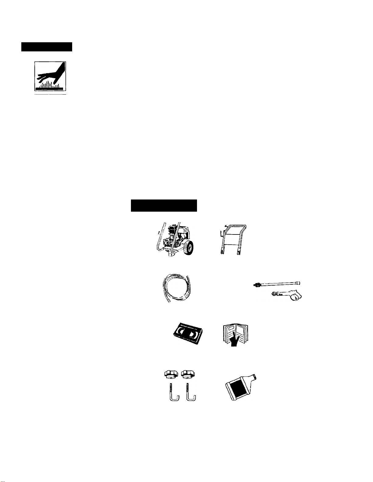
Carton Contents
• Main Unit pressure washer with wheels
• Handle
• High Pressure Hose
• Chemical Pickup Hose and Filter
• Gun
• Wand
Bag Containing
• Video Cassette
• Owners’ Manual
• Nozzle Cleaning Kit and Replacement 0-Rings
• Engine Oil
• Rubber Isolator and Mounting Hardware
• Handle Mounting Hardware
Main Unit pressure washer Handle
with wheels
Chemical Pickup Hose and Filter
Video Cassette Owners’ Manual Nozzle Cleaning Kit
o
High Pressure Hose
Gun and Wand
o
<SBt>
Handle Mounting
Hardware
Engine Oil Rubber Isolator and
Mounting Hardware
0®
Replacement 0-Rings
Page 10

Page 11

Tools Required for Assembly
Adjustable wrench Pliers
1 /2” Socket wrench Funnel
Remove Pressure Washer from Carton
• Open box from the top. Locate and remove from
box, the parts box, which includes gun, handle,
wand,oil, knobs and J bolts. Next remove the parts
bag and the handle.
• Cut carton along dotted lines.
• Remove all carton inserts.
• Roll unit through opening in carton.
NOTE: The high pressure and chemical hose are
located at the bottom of the box.
Preparing the Pressure Washer for First Use
• Note: Included with your pressure washer is a video
tape on how to prepare your unit for operation. It is
recommended you view this tape before performing
the next steps.
1. • Insert handle onto frame.
• Slide J bolts into frame.
• Tighten knobs turning in clockwise direction.
/0^^2237//trighton knob in clockwise
' direction to threaded end of J boit.)
Ilneert J boit here. Threaded end
goes in bottom hole)
Page 12
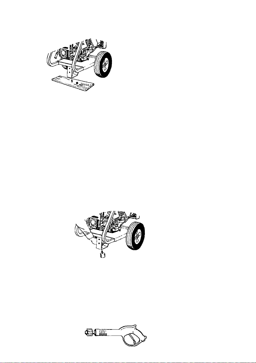
2. • Remove wood plank from the frame of the unit.
An adjustable wrench is required. Discard nut,
bolt and board.
3. • Mount the rubber isolator to the frame. To moun
isolator place threaded end of bolt through the
washer. Next with washer on bolt, place threader
end of bolt through the rubber isolator. Place
threaded portion of isolator through the front
hole location where the wood plank was mounter
on to the pressure washer. Next place lockwashc
over threaded portion of nut that has been placer
through the mounting hole in the pressure washei
and use nut to tighten isolator to the frame.
Tighten nut with an adjustable wrench. All isolatoi
parts are supplied in parts bag.
BOLT
LOCKWASHER
------
A
NUT
PRESSURE , ,
WASHER l„f-|SOLATOR
FRAME C-^WASHER
4. • Connect wand with nozzle extension to gun. To
tighten, turn knob in clockwise direction. Hand
tighten.
Page 13

Cut tie wrap off of high pressure hose. Unwind
high pressure hose to attach the threaded end to
the gun.
Connect chemical hose to the chemical injector
hose barb on pump.
CHEMICAL
INJECTOR
HOSE
PUMP
8.
Your units pump is shipped with a
temporary plug that must be replaced with a
breather cap. This plug is located over the
pump’s oil port. Unscrew and remove this plug.
Remove the breather cap from the bag attached
to the plug and install it in the pump’s oii port.
BREATHEI
CAP
9. • Piace assembied gun and wand on pressure
handle bracket as shown.
7. • Connect high pressure hose to the quick connect
outlet on pressure washer.
QUICK
CONNECT
NOTE: Always keep hose away from engine
muffler.
CAUTION: Failure to replace the plug will result
in serious pump damage.
Checklist
Before going any further piease review the foiiowing:
• Be sure you have completed assembly instruction.
• Double check all fittings to be sure they are tight.
IMPORTANT: Before any attempt to start your pres
sure washer be sure to check engine oii (See Operation
under Engine Oii, page 9.)
Page 14

Page 15

OPERATION
Know Your High Pressure Washer
Read this Owner’s Manual and Safety Rules before
operation of your High Pressure Washer Compare
this illustration with our pressure washer to familiarize
yourself with the location of various controls and
adjustments. Save this manual for future reference.
PUMP- Develops high pressure.
ENGINE OIL FILL- Place where engine oil is poured.
PRESSURE REGULATOR- Allows you to adjust the
pressure of the outlet stream.
ENGINE RUN/STOP SWITCH- Sets engine in starting
mode for recoil starter — Stops running engine.
RECOIL STARTER- Used for starting the engine
manually.
SPRAY GUN ASSEMBLY- Controls the application of
water onto cleaning surface with trigger device.
PUMP OIL FILL- Port where pump oil Is poured and
breather cap is located.
GAS TANK/CAP- Cap is removed and unleaded
gasoline is poured.
CHEMICAL INJECTION TUBE AND FILTER- Mixes
water and detergent in outlet water flow.
HIGH PRESSURE OUTLET- Connection for high pres
sure hose.
CHOKE- Lever used for starting unit.
CHEMICAL
ADJUSTMENT
KNOB
Page 16

Page 17

topping Your Pressure Washer
4 CAUTION; Do not run pump without the water
supply connected and turned on. Failure to do so
will result in pump damage.
To turn pressure washer off place the on/stop switch
to the stop position.
Simply shutting OFF engine will not release pressure
in the system. Squeeze the trigger on the spray gun
for about 3 seconds to relieve pressure. Spray
stream will decrease in length.
MPORTANT: This unit is equipped with a thermal relief
alve. If unit is allowed to run for several minutes
(/ithout pressing the trigger on the spray gun, several
Irops of water may be released through this valve to
;ool the unit. The heated water will be purged from the
)ottom of the pump.
BEFORE STARTING THE ENGINE
fo operate the engine you will need to do the following.
A CAUTION: Always check engine oil level before
every start. Running engine low of oil or out of oil
could result In serious damage.
A CAUTION; Always check pump oil level before
every start. Running pump low on oil could result
in pump damage.
Adding Pump Oil
Before running the high pressure washer, check the
pump oil level by viewing the sight glass on the side of
the pump. When properly filled, the oil will be at the
half way point marked by the two triangles. Your pres
sure washer pump is shipped with oil. Add oil only if oil
level is lower than the half way point on the sight glass.
Do not overfill. Use 30 weight non-detergent oil if
necessary.
A CAUTION: Do Not use engine oil that has been
shipped with your unit in your pump. Engine oil
is detergent and your pump uses a non-detergent
oil. Detergent oil can cause damage to your pump.
Page 18

Engine Oil
Your unit has been shipped without oil in the engine.
A bottle of SAE 30 weight oil is included in the carton.
Remove oil plug located on the side of engine. Using a
funnel, fill engine crankcase up to the last thread in the
oil port. Pour slowly. Oil reading will be inaccurate on
unlevel ground.
NOTE: When adding oil to the engine crankcase, use
a high quality detergent oil classified “For Service SF,
SG, SH rated SAE 30 weight. Use no special addi
tives. Select the oil’s viscosity grade according to
you expected operating temperatures.
SAE viscosity Grades
STAHTIwe TCMPEHATJRE mWQE ANTICIPATEO BEFORE NEXT OLCmNOE
Aircooled engines run hotter than automotive engines.
The use of multi-viscosity oil such as (10W-30, etc.) in
ambient temperatures above 40°F (4°C) will result in
higher than normal oil consumption. If multi-viscosity
oil is used, check the oil level more frequently to
prevent any posssible engine damage due to lack or
lubrication.
Use of SAE30 oil below 40°F (4°C) will result in hard
starting and possible engine damage due to inad
equate lubrication.
Gasoline
Your pressure washer engine is 4 cycle. Use unleaded
fuel only.
A CAUTION: Do not overfill the fuel tank. Always
allow room for fuel expansion.
A WARNING: Never fill fuel tank indoors. Never
fill fuel tank when engine is running or hot. Do
not smoke or have open flame when filling fuel
tank.
Use clean, fresh, regular unleaded gasoline with a
minimum of 85 octane. Do not mix oil with gasoline.
If unleaded fuel is not available, leaded fuel may be
used.
Page 19

IMPORTANT: It is important to prevent gum deposits
from forming in essential fuel system parts such as the
carburetor, fuel filter hose or tank during storage. Also,
experience indicates that alcohol-blended fuels (called
gasohol or using ethanol or methanol) can attract mois
ture which leads to separation and formation of acids
during storage. Acidic gas can damage the fuel system
of an engine while in storage. To avoid engine problems,
the fuel system should be emptied before storage of 30
days or longer. Never use engine or carburetor cleaner
products in the fuel tank or permanent damage may
occur.
NOTE: Never start pressure washer with cutwater
source turned on and connected to pressure washer.
To Start Your Pressure Washer
Make sure fuel shutoff valve is turned to the open
position.
• Remove gas cap
• Add unleaded gasoline, slowly, to fuel tank.
• Do not overfill.
Connect garden hose to the water inlet on the
pressure washer. Tighten by turning water inlet
counterclockwise.
Connect high pressure hose to discharge on pump.
• Connect the garden hose to the water spout and turn
Page 20

• Squeeze trigger on pressure washer wand to relieve a
pressure caused by turning on the water. Water will
spew out of the gun in a thin stream. This will make it
easier to start the engine.
• Engage the safety latch on the spray gun. This locks
the trigger in place and keeps you from accidentally
spraying a high pressure stream.
On the engine there is a choke/run lever. Place lever
to the choke position.
• On the engine there is a throttle control lever. Place
throttle to the rabbit position. Always start engine
with throttle in the rabbit position. Place on/stop
switch to the “on” postion.
• Make sure fuel shut off valve is to the open position.
• Grasp the starter grip and pull slowly until resistance
is felt, then pull firmly to start engine.
• When engine starts, gradually move choke lever to
RUN position.
• If engine does not start after 5 pulls, place choke
back to run position.
• For hot engine starts make sure choke/run lever is in
the run position. Make sure fuel shut off valve is open
and throttle is in the run position.
NOTE: If any leaks are present shut unit down and
tighten fittings.
10
Page 21

(low To Use Your Pressure Washer
Dn the end of your spray gun is a nozzle that you can
wist from side to side. With the adjustable nozzle you
3an adjust the nozzle to either high pressure or low
jressure.
Turn the nozzle in a counter clockwise direction to
achieve low pressure. Turn nozzle clockwise for high
pressure.
For most effective cleaning, keep spray nozzle
between 8 and 24 inches of cleaning surface.
IMPORTANT: If you get spray nozzle too close,
especially on high pressure, you may damage the
cleaning surface.
• The pressure control knob is located on the pump.
You can increase the pressure by turning the knob
clockwise or decrease the pressure by turning the
knob counterclockwise.
NOTE: The maximum pressure for the unit is set at it’s
maximum setting at the factory. Do not attempt to adjust
the pressure higher than this factory setting.
Using Soaps/Chemicals
IMPORTANT: Use soaps and chemicals that are
designed specifically for use with pressure washers. To
apply soap/chemicals follow these steps:
Prepare the soap/chemical as required by your job.
Insert soap/chemical line into your container (soap/
chemicals not included).
Page 22

NOTE: The first step involves applying an appropriate
soap/chemical solution to penetrate and loosen grime.
The soap/chemicai is applied at low pressure to avoid
splashing, over spray and waste. Leave the solution
on surface for 3 to 5 minutes to allow solution to work.
NOTE: The second step involves cleaning the surface
you have prepared with the pressure washer and then
rinsing it clean.
• Turn the adjustable nozzle counterclockwise to low
pressure mode. Soap/chemicals cannot be applied
with nozzle in high pressure position.
• Review the use of the adjustable nozzle.
• Connect garden hose to water inlet (see “To Start Your
Pressure Washer”), check that high pressure hose is
connected to spray gun and pump (see Assembly),
and start engine.
• Apply soap/chemicals to dry surface, starting from the
bottom and working up.
• Allow the soap/chemicals to soak in between 3-5
minutes before washing and rinsing.
• For cleaning, start at lower portion of area to be
washed and work upward, using long, even over
lapping strokes.
Your pressure washer is equipped with a chemical
injector adjustment knob. With the knob fully opened
you will get maximum chemical draw. With knob fully
closed you will get no chemical draw. Turn knob in
counterclockwise direction to achieve more chemical
draw and clockwise for less chemical draw.
After using the pressure washer, it is recommended
the pump, chemical injector and chemical line be
flushed with clear water. To do so, simply place
chemical injector hose in water and siphon for 1 to 2
minutes.
11
Page 23

MAINTENANCE
CUSTOMER RESPONSIBILITIES TABLE
Every 25
MAINTENANCE TASK
PRESSURE WASHER
Check/clean inlet screen. X
Check high pressure hose.
Check soap and chemical hose and filter X
Check gun and wand for leaks. X
Purge pump ofairand contaminants X
Check pump oil X
Change pump oil X
ENGINE
Check oil level X
Change engine oil X
Before each use
X
hours oryearly
Every 50
hours oryearly
Every 100
hours oryearly
Product Specifications
Pressure Washer Specifications
Pressure
Flow Rate
Cleaning Units (psi x GPM)
Engine Specifications
RPM 3600
Rated Horsepower 6.5
Spark Plug Gap
Gasoline Capacity
Oil
0.030” (0.76mm)
2.7 GPM
3 Quarts
SAE 30 weight
2500
6750
General Recommendations
The warranty of the high pressure washer does not
cover items that have been subjected to operator
abuse or negligence. To receive full value from the
warranty, operator must maintain high pressure
washer as instructed in this manual.
Some adjustments will need to be made periodocally to maintain your high pressure washer.
All adjustments in the Maintenance section of this
manual should be made at least once each season.
Once a year you should clean or replace the spark
plug and clean or replace the air filter and check
the gun and wand assembly for wear. A clean
spark plug and clean air filter assure proper
fuel-air mixture and help your engine run better
and last longer.
NOTE: Over time the o-rings in the gun assembly
become worn. Attached to your owners manual is a
replacememt o-ring and split backup ring.
12
Page 24

Page 25

Pressure Washer Maintenance
Check and Clean Inlet Screen: Examine inlet screen
on pump inlet fitting. Clean if clogged replace if torn.
Check High Pressure Hose: High pressure hose can
develop leaks from wear, kinking, abuse. Inspect hose
each time before use. Check for cuts, leaks, abrasions
or bulging of cover, damage or movement of couplings.
If any of these conditions exist, replace hose
immediately.
Check Chemical/Soap Hose: Examine the chemical/
soap hose and clean if clogged. Hose should fit tightly
on pump fitting. Check for leaks and tears. Replace
filter or hose if either is damaged.
Check Gun and Wand: Examine hose connection to
gun making sure it is secure. Test trigger by pressing it
and making sure it springs back into place when you
release it.
Pump Oil
Pump oil level should be checked before each use.
Changing Pump Oii
Oil should be changed after the first 10 hours of opera
tion. Subsequent changes after each 50 hours of opera
tion. To drain oil, simply remove oil plug with a adjust
able wrench. The oil plug is located at the bottom of the
pump. Dispose of used oil. Properly remove pump oil fill
plug. Add 30 weight non-detergent oil. Fill until oil level is
at the mid point on the sight glass.
Purge Pump of Air and Contaminants
To remove the air from the pump, follow these steps:
• Set up the pressure washer as described in
Assembly section and connect the water supply.
• Remove the wand extension from the spray gun.
• Pull the trigger on the gun and hold.
To remove the contaminants from the pump, follow
these steps:
• Set up the pressure washer as described in
ASSEMBLY section, connect the water supply.
• Remove the wand extension from the spray gun.
Start the engine according to instructions in the
OPERATION section.
Page 26

• Pull the trigger on the gun and hold.
• When the water supply is steady and constant,
disengage trigger and refasten the wand extension.
Engine Maintenance Oil
• Oil level should be checked prior to each use
or at least every 5 hours of operation. To check oil see
Adding Engine OH on page 9.
Changing Engine Oil
For a new engine, change oil after the first 5 hours of
operation. Thereafter, change oil after every 50 hours of
operation.
Change the oil while the engine is still warm. The oil will
flow freely and carry away more impurities. Make sure
the engine is level when filling, checking, or changing oil.
Change the oil as follows:
• To keep dirt, grass, etc., out of the engine, clean the
area around the drain plug and oil plug before
removing it.
• Remove the oil drain plug and oil plug. Tilt the engine
slightly towards the oil drain to obtain better drainage.
Be sure to allow ample time for complete drainage.
• Reinstall the drain plug. Make sure it is tightened
securely.
• Fill the crankcase with new oil of the proper type, to
up to the thread in the oil port. Pour slowly.
13
Page 27
Reinstall the oil fill cap or plug and tighten securely.
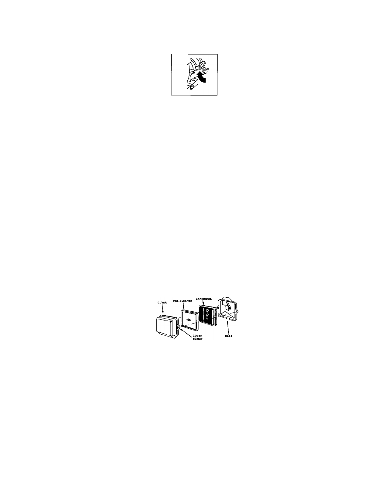
Service Air Cleaner
To service pre-cleaner, wash in liquid detergent and
water. Allow to dry thoroughly before using. Do not oil
pre-cleaner. Replace if very dirty or damaged.
NOTE: Do not use petroleum solvents, e.g., kerosene,
which will cause the cartridge to deteriorate. Do not use
pressurized air to clean cartridge. Pressurized air can
damage the cartridge.
To service air cleaner follow these steps:
1. Unscrew cover screws. Remove cover and air cleaner
assembly.
2. Remove cartiridge from cover, then retainer
(if equipped) and pre-cleaner.
NOTE: Do not use petroleum solvents, e.g., kerosene,
which will cause the cartridge to deteriorate. Do not use
pressurized air to clean cartridge. Pressurized air can
damage the cartiridge.
3. Reassemble pre-cleaner or retainer (if equipped.)
Place in cover with pre-cleaner mesh side toward
cartridge. Place cartridge in retainer in cover.
4. Push cover and air cleaner assembly squarely onto
base (tabs must be in slots, if equipped) and hold
firmly. Tighten cover screws securely.
Keep engine and parts dean!
Page 28

Do not clean engine with a forceful spray of water
because water could contaminate fuel system. With
a brush or cloth clean finger guard after every use to
prevent engine damage caused by overheating.
Before running engine, clean muffler area to remove all
combustible debris.
Clean and Replace Spark Plug
Change the spark plug every 100 hours of operation or
once each year, whichever comes first. This will help
your engine to start easier and run better.
14
Page 29

SERVICE AND ADJUSTMENTS
Carburetor
The carburetor of your high pressure washer is pre-set
at the factory. The carburetor should not be tampered
with. If you pressure washer is used at an altitude in
excess of 5000 feet consult with your nearest Sears
Service Center regarding high altitude set changes.
A CAUTION: Engine speed was properly adjusted
at the factory and should require no additional
adjustment. Do not attempt to change engine
speed. If you believe the engine is running too fast
or too slow, take your pressure washer to a Sears
Authorized Service Center for repair and adjustment.
AWARNING: High engine speeds are dangerous and
increase the risk of personal injury or damage to
equipment.
AWARNING: Low engine speeds impose a heavy
load on the engine and when sufficient engine
power is not available could shorten engine life.
____________________________________
STORAGE
Nozzle Maintenance Hi-Low Lance:
1. Shut off the pressure washer and turn off the water
supply.
2. Disconnect spark plug wire.
3. Pull trigger on gun handle to relieve any water
pressure.
4. Disconnect the wand/lance from the gun.
5. Remove the high-pressure nozzle from the lance.
Remove any obstructions with the nozzle cleaning
tool provided and backflush with clean water.
6. Direct water supply into nozzle end to backflush
loosened particles for 30 seconds.
7. Reassemble the nozzle to the lance using teflon tape
to prevent leaks. Tighten securely.
8. Reconnect wand/lance to gun and turn on water
supply.
9. Start pressure washer and place wand/lance into
high pressure setting to test.
This pressure washer should be stored in such a way to
protect it from freezing. Do not store this unit outdoors
or in an area where temperatures will fall below 32° F.
This can cause extensive damage to this unit.
If unit has to be stored under freezing conditions a non
toxic R.V. anti-freeze can be used to protect from
freezing.
Preparing Pressure Washer for Storage
NOTE: If you do not plan to use your unit for 30 days or
more, unit should be prepared for storage.
Engine Preparation
• First add a fuel stabilizer to the fuel tank.
• Run pressure washer for full 5 minutes to allow fuel
stabilizer to enter the fuel system.
NOTE: While doing this procedure make sure water
supply is turned on and flowing to the unit. NEVER run
unit without water supply running through pump.
• Next shut off engine and disconnect the water supply.
• Disconnect the spark plug wire and remove the spark
plug.
Add one teaspoon of oil through the spark plug hole.
Place rag over spark plug hole and pull the recoil a
few times to lubricate the combustion chamber.
Replace the spark plug, but do not connect the spark
plug wire.
Pump Preparation
• Be sure engine switch is in “OFF” position and spark
plug wire has been removed from spark plug.
• Pull the trigger on the spay gun to release the
pressure in the high pressure hose. Detach high
pressure hose and garden hose from the unit.
• Pull the recoil on the engine 4 to 6 times to discharge
remaining water in pump.
• Tip the unit on the end with the water inlet fitting
pointing upward.
• Pour approximately 1/4 cup of non-toxic R.V. anti
freeze down the fitting where the water hose attaches
to the pump.
• Set unit upright and pull starter handle on engine 4 to
6 times to circulate anti-freeze in pump until anti
freeze is discharged from the pump.
15
Page 30

Page 31

TROUBLESHOOTING
SYMPTOM CAUSE
Engine won’t
start
Won’t Draw
Chemical
Pump running
normaliy but
pressure does
not achieve
rated vaiues
1. Engine throttle is in "OFF" Position.
2. Choke iever has not been piaced to
choke.
3. Pressure buildup after initial use.
1. Nozzle not in chemical draw position.
2. Chemicai screen is obstructed.
3. Chemical screen not working.
4. Chemicai injector orifice obstructed
or stuck.
5. Chemicai injector ciosed.
1. Water suppiy restricted.
2. Nozzie is in iow PSl position.
3. Nozzie incorrect or worn. 3. Check and replace.
4. Pump sucking air. 4. Check that hoses and fittings are air-tight.
5. Nozzie blocked. 5. Clean nozzle.
SOLUTION
1. Slide throttle to "Rabbit" position.
2. Slide choke lever to choke position.
3. Depress trigger gun.
1. Place nozzle to low pressure.
2. Check chemical screen; clean if obstructed.
3. Make sure chemical screen is submerged in
chemical/water.
4. Check and clean.
5. Open chemical injector by turning adjustment
knob.
1. Check water supply and filter screen for.
blockage. Check hoses for blockage, kinks,
leaks, etc.
2. Twist nozzle at end of wand clockwise the high
pressure position.
Fluctuating
Pressure
Pressure drops
after period of
normai use
Pump noisy 1. Water too hot. 1. Reduce temperature below 63° C or 145° F.
Presence of
water in oii (oii
milky).
Water dripping
from pump 2. Fittings Loose.
1. Pump sucking air. 1. Check that hoses and fittings are air tight. Purge air
from garden hose.
2. Garden hose inlet strainer ciogged.
3. Worn Seáis or Packing.
4. Inadequate water supply.
5. Fouled or dirty iniet or discharge
vaives.
6. Leaky discharge hose.
1. Nozzie clogged, partially obstructed. 1. Use nozzle cleaning kit to clear obstruction. (See
2. Nozzle worn.
3. Pump Valves worn, dirty or stuck.
4. Worn pump piston packing.
2, Pump sucking air.
3. Valves dirty or worn.
4. Worn bearings.
1. High humidity.
2. Piston packing and oii seal worn.
1. Thermal relief functioning normal.
3. 0-rings of piston guide or retainer
worn.
4. Piston packing worn.
2. Clean. Check filter frequently.
3. Check and replace.
4. Check hose for kinks.
5. Check flow available to pump. Check for
excessive heat, 145° F or above.
6. Clean inlet and discharge valve assemblies.
Replace if damaged.
Nozzle Maintenance under Service Adjustment.)
2. Clean or replace.
3. Check and replace.
4. Check and replace.
2. Check that hoses and fittings are air tight.
3. Check, clean or replace.
4. Check and replace if necessary.
1. Change Oil.
2. Check and replace oil seals.
1. Protecting pump, if not using pressure washer for
a long period of time, shutoff engine.
2. Tighten.
3. Check and replace.
4. Check and replace.
Oil Dripping
1. Oil seal worn
2. Loose drain plug or worn drain plug
o-ring.
1. Check and replace
2. Tighten drain plug or replace O-ring. Do not overtorque.
16
Page 32

Page 33

PARTS
CRAFTSMAN 2 00 PSI HIGH PRESSURE WASHER 919.762500
22—(g)
----23
KEY# PART NUMBER
1
2
16498 Handle
16471
3 16396
4
5
6
16504
16371
16470 JBolt
DESCRIPTION
Knob
Gun
Tire Simi-Pnuematic
Foot Rubber
7 16503 Frame
8
9
10
11
12
900
16830 0-ring Kit
H100
16823
15111
16501
Chemical Hose
Lance Hi/Low
High Pressure Hose
Decal Front Craftsman
Engine (Refer to Engine Breakdown
Briggs #121432-0112-El)
15
16
17
18
19
20
16727
PK16642 Pump
F035
16829
F464
F064
Decal Operation
High Pressure QC
Adapter- Garden Hose
Nut Pal 1/2"
Srew Hex HDC
KEY# PART NUMBER DESCRIPTION
21
22
23
24
N03515
F119
F078
F112
PARTS NOT ILLUSTRATED
MGP-762500
F078
F119
F066
FI 07
15167
F078
NCT001
F039
17091
17
Nozzle
Hex Nut
Lock Washer
Flat Washer
Owners Manual
Lockwasher, Engine to Frame
Nut Hex 5/16 Engine to Frame
Screw 5/16 Engine to Frame
Lockwasher-Pump to Engine
Srew, Hex- Pump to Engine
Lockwasher- Pump to Engine
Nozzle Cleaning Kit
QC Socket for HP Hose
Nozzle 3 pack 0°, 25°, 40°
Spray Pattern
Page 34

Page 35

PUMP PARTS
CRAFTSMAN 2500 PSI HIGH PRESSURE WASHER 919.678250
^73
f i
PUMP BREAKDOWN MODEL PK16642
rfYPE~F2^
18
Page 36

PUMP PARTS
CRAFTSMAN 2500 PSI HIGH PRESSURE WASHER 919.678250
REF.
NO.
1
2 AR-1260162
3 AR-1269050
4
5
6
7 AR-1260130
8
9
10 AR-1266740
11
12 AR-1780550 Snap ring
13
14
15
16
17 AR-1200430
18 AR-1789010
19 AR-1780040
20 AR-1780060
21
22
PART
NO. DESCRIPTION QTY.
AR-960160 0-Ring 6
Plug 6 24 AR-1260100 Piston washer 3
Complete valve 6
AR-880830 0-Ring 6 27 AR-740290
AR-620301
AR-1780130
AR-1780090
AR-1780010 Pump body
AR-1260790 Circiip
AR-1780490
AR-880130 Oil cap 1 40
AR-1780050
AR-1780510 0-Ring
AR-480480
AR-1260091 Spacer disc
Plug 1
Support ring 3 28
Gasket 3 30 AR-1260460 Seal 3
Piston guide 3
1 32
Cap 1 33
1 36 AR-1780380
1 37
Bearing 1 38
Piston pin 3 41
1 42
Screw 6
Compiete cover 1 67 AR-820440 Grub screw
Con rod 3 68
Guiding piston
0-Ring 3 70
3 69
3 71
REF.
NO.
23
25
31
44
72
73
PUMP BREAKDOWN PK16642
PART
NO.
AR-1780070 Piston
AR-1260110 Nut
AR-880530 Plug
AR-1780100 Rear Piston guide 3
AR-770260 0-Ring
AR-1260440
AR-1381550
AR-680570 Screw 8
AR-1321190
AR-1321080 Snap ring
AR-480671 Seal 1
AR-180030 Screw 4
AR-1789200 Pump head pre-ass. 1
AR-1380580 Gas engine flange
AR-1780590
16747
AR-2973
16506 Thermal Relief Valve 1
DESCRIPTION QTY.
3
3
0-Ring
Gasket
Head 1
Washer
Bearing 1
Hollow shaft %” 1
Chemical Injector 1
Unloader 1
2
2
3
3
8
1
1
1
A=KIT 16739
Valves
Pos. Qty.
3 6
4 6
D=KIT 16745
Water Seals
Pos.
7 3 13
32 3 40
33
Qty. Pos,
3
PARTS KITS
B=KIT 16746
Pistons
Pos. Qty. Pos. Qty.
23 3
F=KIT 16749
Bearings
Qty.
1 71 1
1
C=KIT 16748
Oil Seals for
D Version
10 1
16 1
30 3
42 1
G=KiT 16747
Injector Kit
Pos. Qty.
19
H=KiT 16744
Unioader 0-Ring
Kit
Pos. Qty.
Page 37

Page 38

ENGINE PARTS
CRAFTSMAN 2500 PSI HIGH PRESSURE WASHER 919.678250
21^
22.
BRIGGS ENGINE MODEL #121432-0112-E1
529 @
306
307
REF. PART
NO. NO.
690045(F)
1
399269 Bushing 18
2
692266
3
692549
12
691696 Plug-Oil
15
DESCRIPTION
Cylinder Assembly 17
Seal-Oil 20
Gasket-Crankcase 21 692261
REF. PART
NO. NO. DESCRIPTION
692510 Bearing-Ball 306
22
690047
692550
692551
Cover-Crankcase
Seal-Oil
Cap-Oil Fill 1019
Screw-Hex. 1058 273700 Owner’s Manual
20
REF. PART
NO. NO.
692552
307 690345 Screw-Hex.
529 692553 Grommet
690035
DESCRIPTION
Shield-Cylinder
Label Kit
Page 39

Page 40

ENGINE PARTS
CRAFTSMAN 2500 PSI HIGH PRESSURE WASHER 919.678250
635
337
BRIGGS ENGINE MODEL #121432-0112-El
13^
REF.
NO.
5 499922
7 692554
33
34 499641
35 691304 Spring-Valve
40 692194
45 690977 Tappet-Valve
51 692555
PART
NO.
11 692600
13 691137 Screw-Hex.
499642
124
692568
DESCRIPTION
Head-Cylinder
Gasket-Cylinder Head
Tube-Breather
Valve-Exhaust
Valve-Intake
Retainer-Valve
Gasket-Intake
Screw-Hex.
REF.
PART
NO. DESCRIPTION
NO.
692556
155
691295
189
238 691300 Cap-Valve 1022
305 691108
692557 Screw-Hex. 1026
305A
337 690965
692558
353
19374
383
692186
635
692559 Screw-Hex.
830
Plate-Cylinder Head
Ball-Rocker Arm
Screw-Hex.
Plug-Spark
Nut-Hex.
Wrench-Spark Plug
Boot-Spark Plug
21
REF.
NO.
868
978 691892 Gasket-Plate
1023
1029
1034
PART
NO.
692044 Seal-Valve
691890
499924
692560 Rod-Push
691230
691343
DESCRIPTION
Gasket-Rocker Cover
Cover-Rocker
Arm-Rocker
Guide-Push Rod
Page 41

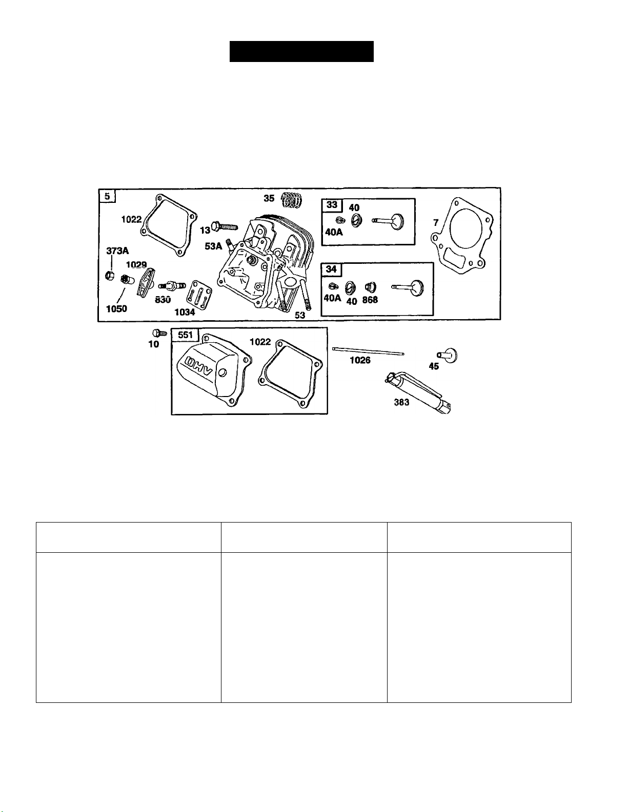
Page 42
ENGINE PARTS
CRAFTSMAN 2700 PSI HIGH PRESSURE WASHER 919.678270
635
337
ENGINE NUMBER 138432-0035-A1
REF.
NO.
40A
•Included in Gasket Set-Part No. 715482
★ Included inValve Overhaul Kit-Part No. 715483
Aincluded in Carburetor Kit-Part No. 715484
♦Included in Gasket Gasket Set -Part No. 715485
PART
NO. DESCRIPTION
715444 Head-Cylinder
5
7 **710624 Gasket-Cylinder Head
710023 Screw-Hex
10
710020 Screw-Hex
13
715445 Valve-Exhaust
33
34 715446 Valve-Intake
710011 Spring-Valve
35
40
710012
715130
Retainer-Valve
Retainer-Valve Plug
REF.
NO.
45 710008 Tappet-Valve 635 710634
53 710148 Stud-Carburetor 830
53A 710099
337 491055
373A
383 19374 Wrench-Spark
551 715450
PART
NO.
710007 Nut-Lock 1029
DESCRIPTION
Mounting 868 •710019
Stud
(Muffler Mounting)
Plug-Spark
Cover-Rocker
22
REF.
NO.
1022 **710626 Gasket-Rocker
1026 710622 Rod-Push
1034
1050 710015 Adjuster-Rocker Arm
PART
NO. DESCRIPTION
Boot-Spark Plug
710016
710014
710017
Stud-Rocker Arm
Seal-Valve
Cover
Arm-Rocker
Guide-Push Rod
Page 43

Page 44

ENGINE PARTS
CRAFTSMAN 2500 PSI HIGH PRESSURE WASHER 919.678250
141 I
124
634A
131
©634
BRIGGS ENGINE MODEL #121432-0112-El
ImT
%
1331
104
975
137
110®
117I110O
REF.
REF.
NO.
51 692555
95
98
PART
NO. DESCRIPTION
Gasket-Intake
(2 Required)
691636
398185 Screw-Idle Speed (Sold in Kit Only)
104 691242 Pin-Float Hinge 130 691181 Valve-Throttle
692567
108
110
111 690572
Screw-Slotted
Valve-Choke
Washer-Seal 133
(Sold in Kit Only)
Spring-Friction
(Choke)
PART
NO. DESCRIPTION
NO.
117 690048 Jet-Main (Standard)
690043
122
127 Plug-Welch
699024 Shaft-Throttle
131
398187 Float-Carburetor
134 398188
Spacer-Carburetor
Valve-Needle
23
REF.
PART
NO.
NO. DESCRIPTION
137 Gasket-Float Bowl
(Sold in Kit Only)
141 699023
163 691887
186 692317 Connector-Hose
634
634A
493640
975
Shaft-Choke
Gasket-Air Cleaner
Washer
(Sold in Kit Only)
Washer
(Sold in Kit Only)
Bowl-Float
Page 45

Page 46

ENGINE PARTS
CRAFTSMAN 2500 PSI HIGH PRESSURE WASHER 919.678250
2221
_75j
©
©
188 f
98A|
%
202
334
232
2651
BRIGGS ENGINE MODEL #121432-0112-E1
843^
663^
211
663^
209
356
356A
PART
REF.
NO.
NO.
495659 Washer Set 232
75
493280 Screw-Idle Speed 265
98A
690877 Screw-Hex.
188
692569 Link-Mechanical
202
692569
209
691798
211
692572 Bracket-Control
222
692573
227
DESCRIPTION
Governor 333
Spring-Governor 334
Spring-Governor 347
Lever-Governor 356
PART
REF.
NO.
NO.
692570
691024
267 690804
692574 Panel-Control 615 692576
281
692605 Armature-Magneto 616
691061
692599 Switch-Rocker 843
692575 Nut-Lock
354
692602 Wire-Stop
DESCRIPTION
Spring-Link
Clamp-Casing 562 691112 Bolt-Governor Level
Screw-Slotted Hex. 592 691251 Nut-Hex.
Screw-Hex.
347
REF.
NO.
356A
663
PART
NO.
692603
692547 Crank-Governor
692577 Screw-Slotted Hex.
692578 Sleeve-Lever
851 493880
DESCRIPTION
Wire-Stop
Retainer-Governor
Terminal-Cable
24
Page 47

Page 48

ENGINE PARTS
CRAFTSMAN 2500 PSI HIGH PRESSURE WASHER 919.678250
967
176 ^
958
BRIGGS ENGINE MODEL #121432-0112-E1
526
373
REF.
NO.
298 690453 Locknut-Muffler 601
300 692580 Muffler-Exhaust
PART
NO. DESCRIPTION
692579 Base-Air Cleaner 346
161
163 691887
176 692127 Screw-Shoulder 373 692582
187 298049 Line-Fuel (Cut to 526 691127
187A
692601 Line-Fuel (Molded)
Gasket-Air Cleaner 346A 692581 Screw-Hex.
Required Length)
PART
REF.
NO.
NO.
690661 Screw-Hex. 863 692595
534
692583
535
691710
692201
642 692584
819 692598
692584
832
819
PART
REF.
DESCRIPTION
Nut-Tinnerman 864
Screw-Hex.
Screw-Slotted Hex.
Filter-Air 967
Clamp-Hose
Cover-Air Cleaner 972 692587 Tank-Fuel
Screw-Hex.
Guard-Muffler
NO.
NO.
863A
692596
692548
957 691654 Cap-Fuel Tank
958 692586
691706
971
691106
DESCRIPTION
Bracket-Muffler
Bracket-Muffler
Adapter-Muffler
Valve-Shutoff
Filter-Air (Pre-Filter)
Screw-Shoulder
25
Page 49

Page 50

ENGINE PARTS
CRAFTSMAN 2500 PSI HIGH PRESSURE WASHER 919.678250
BRIGGS ENGINE MODEL #121432-0112-El
363
332
188 A
PART
REF.
NO.
NO.
692588 Flywheel
23
692608
65
692590
188A
PART
REF.
DESCRIPTION
Screw-Hex.
Screw-Shoulder 332 690662
NO.
NO.
304 692589
691108
305
REF.
PART
DESCRIPTION
Housing-Blower
Screw-Hex. 455 692591 Cup-Flywheel
Nut-Flywheel 1005
26
NO.
NO.
363 19069
692592
DESCRIPTION
Flywheel Puller
Fan-Flywheel
Page 51

Page 52

ENGINE PARTS
CRAFTSMAN 2500 PSI HIGH PRESSURE WASHER 919.678250
608
BRIGGS ENGINE MODEL #121432-0112-E1
623^
REF.
55
PART
NO.
NO.
691422 Housing-Rewind 60 393152
498144 Pulley-Starter 65A 690837
56
58 692593
692594 Insert-Grip
59
REF.
DESCRIPTION
Starter 60A
Rope-Starter (Cut To
Suit)
NO.
373A 690800
456
PART
NO.
691930
692299
373A
65A'^
REF.
DESCRIPTION
Grip-Starter Rope 459
Grip-Starter Rope 608
Screw-Hex. 623
Nut-Hex.
Retainer-Spring
NO.
689
PART
NO.
692260
497830
691696
691855
DESCRIPTION
Pawl-Ratchet
Starter-Rewind
Screw-Shoulder
Spring-Friction
27
Page 53

Page 54

ENGINE PARTS
CRAFTSMAN 2500 PSI HIGH PRESSURE WASHER 919.678250
BRIGGS ENGINE MODEL #121432-0112-E1
REF.
PART
NO.
NO.
3
692266 Seal-Oil 127
7
692554 Gasket-Cylinder Head
12 692549 Gasket-Crankcase
20 692550 Seal-Oil
51
692555
104 691242 Pin-Float Hinge 163
110 Washer-Seal 358
121 690032 Carburetor Kit
122
690043
DESCRIPTION
Gasket-Intake
(2 Required)
(Sold in Kit Only)
Spacer-Carburetor
REF.
NO.
134
137
634
PART
NO. DESCRIPTION
Plug-Welch
(Sold in Kit Only)
398188 Valve-Needle
(Includes Seat)
Gasket-Float Bowl
(Sold in Kit Only)
691887 Gasket-Air Cleaner
690031 Gasket Set
Washer-Shaft
(Throttle Shaft)
(Sold in Kit Only)
28
REF.
PART
NO.
NO.
634A
868
692044
977
690033
978 691892
1022 691890
1033 690034 Kit-Valve Overhaul
DESCRIPTION
Washer-Shaft
Choke Shaft
(Sold in Kit Only)
Seal-Valve
Gasket Set-Carburetor
Gasket-Plate
Gasket-Rocker Cover
Page 55

Page 56

Briggs & Stratton Corporation (B&S), the California Air Resources Board (CARB)
and the United States Environmental Protection Agency (U.S. EPA)
Emission Control System Warranty Statement (Owner’s Defect Warranty Rights and Obligations)
In the interest of the environment, B&S engines that meet strict emis
sion requirements are labeled, ‘This engine conforms to 1995 -1998
California emission regulations for ULGE engines and U.S. EPA
Phase I regulations for small non-road engines.”
EMISSION CONTROL WARRANPr COVERAGE IS APPLICABLE
TO CERTIFIED ENGINES PURCHASED IN CALIFORNIA IN 1995
AND THEREAFTER, WHICH ARE USED IN CALIFORNIA, AND
TO CERTIFIED MODEL YEAR 1997 AND LATER ENGINES
WHICH ARE PURCHASED AND USED ELSEWHERE IN THE
UNITED STATES.
California and United States Emission Control Defects Warranty Statement
CARB, U.S, EPA and B&S are pleased to explain the Emission
Control System Warranty on your 1996 and later utility or lawn and
garden equipment (ULGE) engine. In California, new ULGE engines
produced on or after August 1,1995 must be designed, built and
equipped to meet the State's stringent anti-smog standards/ Else
where in the United States, new non-road, spark-ignition engines
certified for model year 1997 and later, must meet similar standards
set forth by the U.S. EPA. B&S must warrant the emission control
there has been no abuse, neglect or improper maintenance of your
ULGE engine.
Your emission control system includes parts such as the carburetor,
air cleaner, ignition system, muffler and catalytic converter. Also
Included maybe connectors and other emission related assemblies.
Where a warrantable condition exists, B&S will repair your ULGE
engine at no cost to you including diagnosis, parts and labor.
system on your engine for the periods of time listed below, provided
Briggs & Stratton Emission Control Defects Warranty Coverage
ULGE engines are warranted relative to emission control parts below. If any coveredpart on yourengine is defective, the partwill be
defects for a period of two years, subject to provisions set forth repaired or replaced by B&S.
Owner’s Warranty Responsibilities
As the ULGE engine owner, you are responsible tor the performance
of the required maintenance listed in your Operator/Owner Manual.
B&S recommends that you retain all your receipts covering mainte
nance on your ULGE engine, but B&S cannot deny warranty solely
(or the lack of receipts or for your failure to ensure the performance of
all scheduled maintenance.
As the ULGE engine owner, you should however be aware that B&S
may deny you warranty coverage if your ULGE engine or a part has
failed due to abuse, neglect, improper maintenance or unapproved
modifications.
You are responsible (or presenting your ULGE engine to an Autho
rized B&S Service Dealer as soon as a problem exists. The undis
puted warranty repairs should be completed in a reasonable amount
of time, not to exceed 30 days.
If you have any questions regarding your warranty rights and
responsibilities, you should contact a B&S Service Representative
at 1-414-259-5262.
The emission warranty is a defects warranty. Defects are judged on
normal engine performance. The warranty is not related to an in-use
emission test.
Briggs & Stratton Emission Controi Defects Warranty Provisions
The following are specific provisions relative to your Emission Control Defects Warranty Coverage. It is in addition to the B&S engine warranty
for non-regulated engines found in the Operator/Owner Manual.
1.
Warranted Parts 3.
Coverage under this warranty extends only to the parts listed
below (the emission control systems parts) to the extent these
parts were present on the engine purchased.
Fuel Metering System
a.
• Cold start enrichment system (soft choke)
• Carburetor and internal parts
• Fuel Pump
Air Induction System
• Air cleaner
• Intake manifold
Ignition System
c.
• Spark plug(s)
• Magneto ignition system
Catalyst System 5.
d.
• Catalytic converter
• Exhaust manifold
• Air injection system or pulse valve
Miscellaneous Items Used in Above Systems
e.
• Vacuum, temperature, position, time sensitive valves
and switches
• Connectors and assemblies
Length of Coverage
B&S warrants to the initial owner and each subsequent purchaser
that the Warranted Parts shall be free from defects in materials 6.
and workmanship which caused the failure of the Warranted
Parts for a period of two years from the date the engine is deliv
ered to a retail purchaser.
No Charge
Repair or replacement of any Warranted Part will be performed
at no charge to the owner, including diagnostic labor which leads
to the determination that a Warranted Part is defective, if the
diagnostic work is performed at an Authorized B&S Service
Dealer. For emissions warranty service contact your nearest
Authorized B&S Service Dealer as listed in the “Yellow Pages”
under "Engines, Gasoline,” "Gasoline Engines,” “Lawn
Mowers,” or similar category.
4.
Claims and Coverage Exclusions
Warranty claims shall be filed in accordance with the provisions
of the B&S Engine Warranty Policy. Warranty coverage shall be
excluded for failures of Warranted Parts which are not original
B&S parts or because of abuse, neglect or improper mainte
nance as set forth in the B&S Engine Warranty Policy. B&S is not
liable to cover failures of Warranted Parts caused by the use of
add-on, non-original, or modified parts.
Maintenance
Any Warranted Part which is not scheduled for replacement as
required maintenance or which is scheduled only for regular
inspection to the effect of “repair or replace as necessary” shall
be warranted as to defects for the warranty period. Any
Warranted Part which is scheduled for replacement as required
maintenance shall be warranted as to defects only for the period
of time up to the first scheduled replacement for that part. Any
replacement part that is equivalent in performance and durability
may bo used in the performance of any maintenance or repairs.
The owner Is responsible for the performance of all required
maintenance, as defined in the B&S Operator/Owner Manual.
Consequential Coverage
Coverage hereunder shall extend to the failure of any engine
components caused by the failure of any Warranted Part still
under warranty.
29
Page 57

Page 58

Briggs & Stratton welcomes warranty repair and apologizes
to you for being inconvenienced. Any Authorized Service
Dealer may perform warranty repairs. Most warranty repairs
are handled routinely, but sometimes requests for warranty
service may not be appropriate. For example, warranty would
not apply if engine damage occurred because of misuse, lack
of routine maintenance, shipping, handling, warehousing or
improper installation. Simiiarly, warranty is void if the serial
number of the engine has been removed or the engine has
been altered or modified.
If a customer differs with the decision of the Service*Dealer, an
investigation wili be made to determine whether the warranty
appiies. Ask the Service Dealer to submit ail supporting facts to
his Distributor or the Factory for review, if the Distributor or the
Factory decides that the ciaim is justified, the customer will be
fully reimbursed for those items that are defective. To avoid
misunderstanding which might occur between the customer
and the Dealer, listed below are some of the causes of engine
failure that the warranty does not cover.
Improper maintenance;
The life of an engine depends upon the conditions under
which it operates, and the care it receives. Some applications,
such as tiilers, pumps and rotary mowers, are very often used
in dusty or dirty conditions, which can cause what appears to
be premature wear. Such wear, when caused by dirt, dust,
spark plug cleaning grit, or other abrasive material that has
entered the engine because of improper maintenance, is not
covered by warranty.
This warranty covers engine reiated defective materiai
and/or workmanship oniy. and not repiacement or refund
of the equipment to which the engine may be mounted.
Nor does the warranty extend to repairs required
because of:
1. PROBLEMS CAUSED BY PARTS THAT ARE
ORIGINAL BRIGGS & STRATTON PARTS.
2. Equipment controls or installations that prevent starting,
cause unsatisfactory engine performance, or shorten
engine life. (Contact equipment manufacturer.)
3. Leaking carburetors, ciogged fuel pipes, sticking vaives,
or other damage, caused by using contaminated or stale
fuel. (Use clean, fresh, lead-free gasoline and Briggs &
Stratton gasoline stabilizer. Part No. 5041.)
NOT
Page 59

4. Parts which are scored or broken because an engine was
operated with insufficient or contaminated lubricating oil,
or an incorrect grade of lubricating oil (check oil level daily
or after every 8 hours of operation. Refill when necessary
and change at recommended intervals.) Read "Owner’s
Manual.”
5. Repair or adjustment of associated parts or assemblies
such as clutches, transmissions, remote controls, etc.,
which are not manufactured by Briggs & Stratton.
6. Damage or wear to parts caused by dirt, which entered
the engine because of improper air cleaner maintenance,
re-assembly, or use of a non-original air cleaner element
or cartridge. (At recommended intervals, clean and re-oil
the Oil-Foam® element or the foam pre-cleaner, and
replace the cartridge.) Read “Owner's Manual.”
7. Parts damaged by overspeeding, or overheating caused
by grass, debris, or dirt, which plugs or clogs the cooling
fins, or flywheel area, or damage caused by operating the
engine in a confined area without sufficient ventilation.
(Clean fins on the cylinder, cylinder head and flywheel at
recommended intervals.) Read “Owner’s Manual.”
8. Engine or equipment parts broken by excessive vibration
caused by a loose engine mounting, loose cutter blades,
unbalanced blades or loose or unbalanced impellers,
improper attachment of equipment to engine crankshaft,
overspeeding or other abuse in operation.
9. A bent or broken crankshaft, caused by striking a solid
object with the cutter blade of a rotary lawn mower, or
excessive v-belt tightness.
10. Routine tune-up or adjustment of the engine.
11. Engine or engine component failure, i.e., combustion
chamber, valves, valve seats, valve guides, or burned
starter motor windings, caused by the use of alternate
fuels such as, liquified petroleum, natural gas, altered
gasolines, etc.
30
Page 60

OWNERS MANUAL FOR
CRAFTSMAN
MODEL NO.
919.678250
SERVICE
High Pressure Washer
The model number of your Sears Air Compressor can be found on the
maintenance label on the top of the shroud or on the bar code label on
the rear of the air tank.
SERVICE AND REPAIR PARTS
CALL 1-800-665-4455*
Keep this number handy should you require a service call or need to
order repair parts.
If ordering parts make sure you have the name, make and model no. of
the merchandise and the name and number of
the part you wish to order.
HOW TO ORDER
REPAIR PARTS
'^If calling locally, please use one of the following numbers:
Regina - 566-5124 Montreal -333-5740
Toronto - 744-4900 Halifax - 454-2444
Kitchener - 894-7590 Ottawa - 738-4440
Vancouver - 420-8211
WHEN ORDERING REPAIR PARTS, ALWAYS GIVE THE
FOLLOWING INFORMATION:
PART NUMBER
MODEL NUMBER
All parts listed may be ordered from any Sears Service Center
and most Sears stores.
If the parts you need are not stocked locally, your order will be
electronically transmitted to a Sears Repair Parts Distribution
Center for handling.
PART DESCRIPTION
NAME OF ITEM
Sold By Sears Canada, Inc., Toronto, Ont. MSB 2B8
Page 61

Page 62

SERVICE NOTES
Page 63

SERVICE NOTES
Page 64

SERVICE NOTES
 Loading...