

Page 1

Owner’s Manual
Oil Lubricated
Single Stage
Horizontal Portable
AIR COMPRESSOR
Model No.
919.195411
• Safety Guidelines
• Assembly
• Operation
• Maintenance
• Service and Adjustments
• Troubleshooting
• Repair Parts
• Español
CAUTION: Read the Safety Guidelines
and All Instructions Carefully Before
Operating.
Sears, Roebuck and Co., Hoffman Estates, IL 60179 U.S.A.
A09713 Rev. 0 1/3/05
Visit our Craftsman website: www.sears.com/craftsman
Page 2

TABLE OF CONTENTS
WARRANTY. . . . . . . . . . . . . . . . . . . . . . . . . . . . . . . . . . . . . . . . . . . . . . . . 2
SPECIFICATION CHART . . . . . . . . . . . . . . . . . . . . . . . . . . . . . . . . . . . . . 3
SAFETY GUIDELINES. . . . . . . . . . . . . . . . . . . . . . . . . . . . . . . . . . . . . . 3-8
GLOSSARY . . . . . . . . . . . . . . . . . . . . . . . . . . . . . . . . . . . . . . . . . . . . . . . . 9
ACCESSORIES . . . . . . . . . . . . . . . . . . . . . . . . . . . . . . . . . . . . . . . . . . . . 9
DUTY CYCLE . . . . . . . . . . . . . . . . . . . . . . . . . . . . . . . . . . . . . . . . . . . . . . 9
ASSEMBLY . . . . . . . . . . . . . . . . . . . . . . . . . . . . . . . . . . . . . . . . . . . . 10-12
INSTALLATION . . . . . . . . . . . . . . . . . . . . . . . . . . . . . . . . . . . . . . . . . 12-13
OPERATION . . . . . . . . . . . . . . . . . . . . . . . . . . . . . . . . . . . . . . . . . . . 14-16
MAINTENANCE. . . . . . . . . . . . . . . . . . . . . . . . . . . . . . . . . . . . . . . . . 17-19
SERVICE AND ADJUSTMENTS. . . . . . . . . . . . . . . . . . . . . . . . . . . . 20-22
STORAGE . . . . . . . . . . . . . . . . . . . . . . . . . . . . . . . . . . . . . . . . . . . . . . . . 23
TROUBLESHOOTING GUIDE . . . . . . . . . . . . . . . . . . . . . . . . . . . . . 24-27
REPAIR PARTS . . . . . . . . . . . . . . . . . . . . . . . . . . . . . . . . . . . . . . . . . 28-31
ESPAÑOL. . . . . . . . . . . . . . . . . . . . . . . . . . . . . . . . . . . . . . . . . . . . . . 32-57
NOTES . . . . . . . . . . . . . . . . . . . . . . . . . . . . . . . . . . . . . . . . . . . . . . . . . . 58
REPAIR PROTECTION AGREEMENTS . . . . . . . . . . . . . . . . . . . . . . . . . 59
HOW TO ORDER REPAIR PARTS . . . . . . . . . . . . . . . . . . . . . .Back Cover
AIR COMPRESSOR WARRANTY
FULL ONE YEAR WARRANTY AIR COMPRESSOR
If this CRAFTSMAN Air Compressor fails due to a defect in material or
workmanship within one year from the date of purchase, Sears will at
its option repair or replace it free of charge. Contact your nearest Sears
Service Center (1-800-4-MY-HOME®) to arrange for repair, or return the Air
Compressor to the place of purchase for replacement.
If this Air Compressor is used for commercial or rental purposes, this warranty
applies for only ninety days from the date of purchase.
This warranty gives you specific legal rights and you may have other rights
which vary from state to state.
Sears, Roebuck and Co., Dept. 817WA, Hoffman Estates, IL 60179
A09713
2- ENG
Page 3
SPECIFICATION TABLE
Model No. 919.195411
Running HP 2.0
Bore 2.875"
Stroke 2.0"
Voltage-Single Phase 120/240
Minimum Branch Circuit Requirement 15 amps
Fuse Type Time Delay
Air Tank Capacity 25 gallons
Approximate Cut-in Pressure 120
Approximate Cut-out Pressure 150
SCFM @ 40 psig 8.6
SCFM @ 90 psig 6.8
Refer to Glossary for abbreviations.
SAFETY GUIDELINES - DEFINITIONS
This manual contains information that is important for you to know and
understand. This information relates to protecting YOUR SAFETY and
PREVENTING EQUIPMENT PROBLEMS. To help you recognize this
information, we use the symbols below. Please read the manual and pay
attention to these sections.
Indicates an
imminently hazardous
situation which, if not avoided, will
result in death or serious injury.
Indicates a potentially
hazardous situation
which, if not avoided, could result in
death or serious injury.
which, if not avoided, may result in
minor or moderate injury.
indicates a potentially hazardous
situation which, if not avoided, may
result in property damage.
Indicates a potentially
hazardous situation
Used without the
safety alert symbol
IMPORTANT SAFETY INSTRUCTIONS
Some dust created by power sanding, sawing, grinding, drilling, and
California) to cause cancer, birth defects or other reproductive harm. Some example of
these chemicals are:
•
lead from lead-based paints
•
crystalline silica from bricks and cement and other masonry products
•
arsenic and chromium from chemically-treated lumber
Your risk from these exposures varies, depending on how often you do this type of work.
To reduce your exposure to these chemicals: work in a well ventilated area, and work
with approved safety equipment, always wear MSHA/NIOSH approved, properly fitting
face mask or respirator when using such tools.
When using air tools, basic safety precautions should always be followed to reduce the
risk of personal injury.
other construction activities contains chemicals known (to the State of
3- ENG
A09713
Page 4

IMPORTANT SAFETY INSTRUCTIONS
Save these instructions
Improper operation or maintenance of this product could result in serious injury and
property damage. Read and understand all warnings and operation instructions before
using this equipment.
HAZARD
WARNING: Risk of explosion or fire
What Could Happen
It is normal for electrical contacts
within the motor and pressure switch to
spark.
If electrical sparks from compressor
come into contact with flammable
vapors, they may ignite, causing fire or
explosion.
Restricting any of the compressor
ventilation openings will cause serious
overheating and could cause fire.
Unattended operation of this product
could result in personal injury or
property damage. To reduce the risk
of fire, do not allow the compressor to
operate unattended.
How To Prevent It
Always operate the compressor in a
well ventilated area free of combustible
materials, gasoline, or solvent vapors.
If spraying flammable materials, locate
compressor at least 20 feet away from
spray area. An additional length of hose
may be required.
Store flammable materials in a secure
location away from compressor.
Never place objects against or on top
of compressor. Operate compressor
in an open area at least 12 inches
away from any wall or obstruction that
would restrict the flow of fresh air to the
ventilation openings.
Operate compressor in a clean, dry well
ventilated area. Do not operate unit
indoors or in any confined area.
Always remain in attendance with the
product when it is operating.
Always disconnect electrical power by
moving pressure switch lever to the off
position and drain tank daily or after
each use.
A09713
4- ENG
Page 5

HAZARD
WARNING: Risk of Bursting
Air Tank: The following conditions could lead to a weakening of the tank, and result
in a violent tank explosion and could cause property damage or serious injury.
What Could Happen
Failure to properly drain condensed
water from tank, causing rust and
thinning of the steel tank.
Modifications or attempted repairs to
the tank.
Unauthorized modifications to the
unloader valve, safety valve, or any
other components which control tank
pressure.
Excessive vibration can weaken the
air tank and cause rupture or
explosion
ATTACHMENTS & ACCESSORIES:
Exceeding the pressure rating of
air tools, spray guns, air operated
accessories, tires, and other inflatables
can cause them to explode or fly apart,
and could result in serious injury.
HAZARD
How To Prevent It
Drain tank daily or after each use.
If tank develops a leak, replace it
immediately with a new tank or replace
the entire compressor.
Never drill into, weld, or make any
modifications to the tank or its
attachments.
The tank is designed to withstand specific
operating pressures. Never make
adjustments or parts substitutions
to alter the factory set operating
pressures.
For essential control of air pressure,
you must install a pressure regulator
and pressure gauge to the air outlet
(if not equipped) of your compressor.
Follow the equipment manufacturers
recommendation and never exceed the
maximum allowable pressure rating of
attachments. Never use compressor
to inflate small low pressure objects
such as children’s toys, footballs,
basketballs, etc.
WARNING: Risk from Flying Objects
What Could Happen
The compressed air stream can cause
soft tissue damage to exposed skin
and can propel dirt, chips, loose
particles, and small objects at high
speed, resulting in property damage or
personal injury.
How To Prevent It
Always wear ANSI Z87.1 approved safety
glasses with side shields when using the
compressor.
Never point any nozzle or sprayer
toward any part of the body or at other
people or animals.
Always turn the compressor off and
bleed pressure from the air hose and tank
before attempting maintenance, attaching
tools or accessories.
5- ENG
A09713
Page 6

HAZARD
WARNING: Risk of Electrical Shock
What Could Happen
Your air compressor is powered by
electricity. Like any other electrically
powered device, If it is not used
properly it may cause electric shock.
Repairs attempted by unqualified
personnel can result in serious injury
or death by electrocution.
Electrical Grounding: Failure to provide
adequate grounding to this product
could result in serious injury or death
from electrocution.
See grounding instructions.
HAZARD
WARNING: Risk of Breathing
What Could Happen
The compressed air directly from your
compressor is not safe for breathing.
The air stream may contain carbon
monoxide, toxic vapors, or solid
particles from the tank. Breathing these
contaminants can cause serious injury
or death.
How To Prevent It
Never operate the compressor outdoors
when it is raining or in wet conditions.
Never operate compressor with
protective covers removed or damaged.
Any electrical wiring or repairs required
on this product should be performed by
authorized service center personnel
in accordance with national and local
electrical codes.
Make certain that the electrical circuit
to which the compressor is connected
provides proper electrical grounding,
correct voltage and adequate fuse
protection.
How To Prevent It
Air obtained directly from the compressor
should never be used to supply air for
human consumption. In order to use air
produced by this compressor for breathing,
suitable filters and in-line safety
equipment must be properly installed.
In-line filters and safety equipment
used in conjunction with the compressor
must be capable of treating air to all
applicable local and federal codes prior
to human consumption.
Sprayed materials such as paint, paint
solvents, paint remover, insecticides,
weed killers, may contain harmful
vapors and poisons.
A09713
Work in an area with good cross
ventilation. Read and follow the safety
instructions provided on the label or
safety data sheets for the materials
you are spraying. Use a NIOSH/ MSHA
approved respirator designed for use with
your specific application.
6- ENG
Page 7

HAZARD
WARNING: Risk of Burns
What Could Happen
Touching exposed metal such as the
compressor head or outlet tubes, can
result in serious burns.
HAZARD
WARNING: Risk from Moving Parts
What Could Happen
Moving parts such as the pulley, flywheel,
and belt can cause serious injury
they come into contact with you or your
clothing.
Attempting to operate
damaged or missing parts
to repair compressor with protective
shrouds removed can expose you to
moving parts and
injury.
compressor with
can result in serious
if
or attempting
HAZARD
WARNING: Risk of Falling
How To Prevent It
Never touch any exposed metal parts
on compressor during or immediately
after operation. Compressor will remain
hot for several minutes after operation.
Do not reach around protective shrouds
or attempt maintenance until unit has
been allowed to cool.
How To Prevent It
Never operate the compressor with
guards
or covers which are damaged or
removed.
Any repairs required on this product
should be performed by authorized
service center personnel.
What Could Happen
A portable
a table, workbench, or roof c
damage to the compressor and could
result in serious injury or death to the
operator.
compressor can fall from
ausing
How To Prevent It
Always operate compressor in a stable
secure position to prevent accidental
movement of the unit.
compressor on a roof or other elevated
position. Use additional air hose to
reach high locations.
7- ENG
Never operate
A09713
Page 8

HAZARD
WARNING: Risk of Serious Injury or Property Damage When
Transporting Compressor
(Fire, Inhalation, Damage to Vehicle Surfaces)
What Could Happen
Oil can leak or spill and could result
in fire or breathing hazard; serious
injury or death can result. oil leaks will
damage carpet, paint or other surfaces
in vehicles or trailers.
Always place COMPRESSOR on a
protective mat when transporting to
protect against damage to vehicle from
leaks. Remove COMPRESSOR from
vehicle immediately upon arrival at your
destination.
How To Prevent It
HAZARD
WARNING: Risk of Unsafe Operation
What Could Happen
Unsafe operation of your air compressor
could lead to serious injury or death to
you or others.
SAVE THESE INSTRUCTIONS
How To Prevent It
Review and understand all instructions
and warnings in this manual.
Become familiar with the operation and
controls of the air compressor.
Keep operating area clear of all persons,
pets, and obstacles.
Keep children away from the air
compressor at all times.
Do not operate the product when
fatigued or under the influence of
alcohol or drugs. Stay alert at all times.
Never defeat the safety features of this
product.
Equip area of operation with a fire
extinguisher.
Do not operate machine with missing,
broken, or unauthorized parts.
A09713
8- ENG
Page 9

GLOSSARY
Become familiar with these terms
before operating the unit.
CFM: Cubic feet per minute.
SCFM: Standard cubic feet per
minute; a unit of measure of air
delivery.
PSIG: Pounds per square inch
gauge; a unit of measure of pressure.
Code Certification: Products that
bear one or more of the following
marks: UL, CUL, ETL, CETL, have
been evaluated by OSHA certified
independent safety laboratories and
meet the applicable Underwriters
Laboratories Standards for Safety.
Cut-In Pressure: While the motor
is off, air tank pressure drops as
you continue to use your accessory.
When the tank pressure drops to a
certain low level the motor will restart
automatically. The low pressure
at which the motor automatically
restarts is called "cut-in" pressure.
Cut-Out Pressure: When an air
compressor is turned on and begins
to run, air pressure in the air tank
begins to build. It builds to a certain
high pressure before the motor
automatically shuts off, protecting
your air tank from pressure higher
than its capacity. The high pressure
at which the motor shuts off is called
"cut-out" pressure.
Branch Circuit: Circuit carrying
electricity from electrical panel to
outlet.
ACCESSORIES
This unit is capable of powering the following Accessories. The accessories are
available through the current Power and Hand Tool Catalog or full-line Sears
stores.
Accessories
• In Line Filter
• Tire Air Chuck
• Quick Connector Sets (various
sizes)
• Air Pressure Regulators
• Oil Fog Lubricators
DUTY CYCLE
This air compressor pump is
capable of running continuously.
However, to prolong the life of your
air compressor, it is recommended
that a 50%-75% average duty
• Air Hose:1/4", 3/8" or 1/2" inside
diameter in various lengths
Refer to the selection chart located
on the unit to select the tools this unit
is capable of powering.
cycle be maintained; that is, the air
compressor pump should not run
more than 30-45 minutes in any given
hour.
9- ENG
A09713
Page 10

ASSEMBLY
Contents of Carton
1 - Air Compressor
2 - Wheels
2 - Shoulder Bolts, 3/8-16
2 - Hex Nuts, 3/8-16
1 - Handle
1 - Handle Grip
2 - Cap Screws
2 - 1/4-20 Hex Nuts
2 - Retainer Clips
2 - Flat Washers
2 - Rubber Bumpers
2 - Screws, 1/4-20 x 3/4
Tools Required for Assembly
1 - 9/16" socket or open end wrench
1 - 1/2" socket or open end wrench
Unpacking
Remove unit from carton and discard
all packaging. NOTE: Save all parts
bags.
To Install Handle
The wheels and
handle do not
provide adequate clearance,
stability, or support for pulling the
unit up and down stairs or steps.
The unit must be lifted or pushed
up a ramp. Do not lift the unit by
the manifold assembly; the unit
could be damaged.
1. To make installation easier,
submerge handle grip into warm
soapy water. Remove handle
grip from soapy water and slide
onto handle.
2. Insert the open ends of the
handle under the saddle. Before
attaching handle, you may have
to pull the open ends of the
handle apart so they fit tightly
against the side of the saddle.
Looking in from the open end of
the saddle, position the handle
toward the two bent tabs, on the
inside walls of the saddle.
A09713
Bent Tabs
Saddle
3. Slowly push the open ends of
the handle onto both tabs at the
same time. Continue pushing the
handle into the saddle until the
holes on the side of the saddle
and handle are in line.
Open End
Of Handle
Saddle Hole
Bent Tabs
4. Guide the straight end of each
retaining clip through the saddle
hole and both handle holes.
Retaining Clip
Handle
Inserted
On Tabs
10- ENG
Open End
Saddle
Of
Open End
Of Handle
Handle Hol
e
Page 11

5. Rotate each retaining clip
clockwise and press down until it
snaps into place over the handle.
Retaining Clip
Handle
Assemble Rubber Feet
1. Attach rubber feet with the
screws, washers and nuts
provided as shown in figure
below.
2. Tighten securely.
Nut
Wheel
6. If the handle has excessive
movement, it is improperly
installed. Check the following.
A. Are both tabs inside the
handle (Step #3)?
B. Does each clip pass through
both the saddle and handle
(Step #4)?
To Assemble Wheels
It will be necessary
to brace or support
one side of the air compressor
when installing the wheels because
the compressor will have a
tendency to tip.
1. Attach wheels with shoulder
bolts and nuts as shown.
2. Tighten securely. NOTE: The air
compressor will sit level if the
wheels are properly installed.
The wheels and
handle do not
provide adequate clearance,
stability or support for pulling the
unit up and down stairs or steps.
The unit must be lifted, or pushed
up a ramp.
Nut
Flat Washer
Rubber Foot
Screw
Shoulder
Bolt
To Add Oil To Pump
Compressors are
shipped without
oil. A small amount of oil may be
present in the pump upon receipt
of the air compressor. This is
due to plant testing and does not
mean the pump contains oil. Do
not attempt to operate this air
compressor without first adding oil
to the crankcase. Serious damage
can result from even limited
operation unless filled with oil and
broken in correctly. Make sure
to closely follow initial start-up
procedures.
Use air compressor
oil only.
Viscosity motor oils, like 10W30,
should not be used in an air
compressor. They leave carbon
deposits on critical components,
thus reducing performance and
compressor life.
Use an air compressor oil
NOTE:
such as Sears item number 9-16426
or SAE-20 (API CG/CD heavy duty
motor oil. Under extreme winter
conditions use SAE-10 weight oil.
Multi-
11- ENG
A09713
Page 12

To Add Oil
Drain tank to
release air pressure
before removing the oil fill cap or
oil drain plug.
1. Place unit on a level surface.
2. Remove oil fill plug (A) and
slowly add compressor oil until
it is even with the top of the oil
fill hole. NOTE: Do not allow oil
to be lower than 3/8" (6 threads)
from the top at any time. When
filling the crankcase, the oil flows
very slowly into the pump. If the
oil is added too quickly, it will
overflow and appear to be full.
INSTALLATION
NOTE:
Crankcase oil capacity is
approximately 16 fluid ounces.
3. Replace oil fill plug.
A
Location of the Air Compressor
Locate the air compressor in a
clean, dry and well ventilated area.
The air compressor should be
located at least 12" away from the
wall or other obstructions that will
interfere with the flow of air. The
air compressor pump and shroud
are designed to allow for proper
cooling. The ventilation openings
on the compressor are necessary
to maintain proper operating
temperature. Do not place rags or
other containers on or near these
openings.
GROUNDING INSTRUCTIONS
RISK OF
ELECTRICAL
SHOCK. In the event of a short
circuit, grounding reduces the risk
of shock by providing an escape
wire for the electric current. This
air compressor must be properly
grounded.
The portable air compressor is
equipped with a cord having a
grounding wire with an appropriate
grounding plug (see following
illustrations). The plug must be used
with an outlet that has been installed
and grounded in accordance with all
local codes and ordinances.
1. The cord set and plug with this
unit contains a grounding pin.
This plug MUST be used with a
grounded outlet.
IMPORTANT:
The outlet being used
must be installed and grounded in
accordance with all local codes and
ordinances.
2. Make sure the outlet being used
has the same configuration
as the grounded plug.
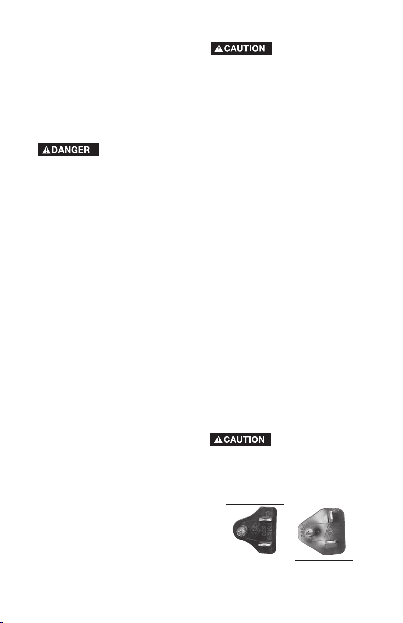
NOT USE AN ADAPTER.
DO
See
illustration.
Plug
A09713
12- ENG
Grounding Pin
Grounded
Outlets
Page 13
3. Inspect the plug and cord before
each use. Do not use if there are
signs of damage.
4. If these grounding instructions
are not completely understood,
or if in doubt as to whether
the compressor is properly
grounded, have the installation
checked by a qualified
electrician.
RISK OF
ELECTRICAL
SHOCK. IMPROPER GROUNDING
CAN RESULT IN ELECTRICAL
SHOCK.
Do not modify the plug provided. If
it does not fit the available outlet,
a correct outlet should be installed
by a qualified electrician.
Repairs to the cord set or plug
MUST be made by a qualified
electrician.
Extension Cords
Using extension cords is not
recommended. The use of extension
cords will cause voltage to drop
resulting in power loss to the motor
and overheating.
Instead of using an extension cord,
increase the working reach of the
air hose by attaching another length
of hose to its end. Attach additional
lengths of hose as needed.
If an extension cord must be used,
be sure it is:
• a 3-wire extension cord that has
a 3-blade grounding plug, and a
3-slot receptacle that will accept
the plug on the product
• in good condition
• no longer than 50 feet
• 12 gauge (AWG) or larger. (Wire
size increases as gauge number
decreases. 10 AWG and 8 AWG
may also be used. DO NOT
USE 14 OR 16 AWG.)
Risk of Unsafe
Operation. Certain
air compressors can be operated
on a 15 amp circuit if the following
conditions are met.
1. Voltage supply to circuit must
comply with the National
Electrical Code.
2. Circuit is not used to supply any
other electrical needs.
3. Extension cords comply with
specifications.
4. Circuit is equipped with a
15 amp circuit breaker or 15
amp time delay fuse. NOTE: If
compressor is connected to a
circuit protected by fuses, use
only time delay fuses. Time delay
fuses should be marked "D" in
Canada and "T" in the US.
If any of the above conditions
cannot be met, or if operation of
the compressor repeatedly causes
interruption of the power, it may be
necessary to operate it from a 20
amp circuit. It is not necessary to
change the cord set.
120/240 Dual Voltage Motor
This model has a dual voltage motor,
120 and 240 volt. It is wired for 120
volt but can be converted to 240 volt
operation. Instructions for connecting
the motor for operation at 240 volt
can be found printed on the label
attached to the side of the motor.
When converting to
240V operation, the
attached three-prong 120V cord
assembly must be replaced with a
three-pronged 240V cord assembly
(K-0080) that can be purchased
through a Sears Service Center.
Voltage and Circuit Protection
Refer to the specification chart for
the voltage and minimum branch
circuit requirements.
13- ENG
120 Volt Plug
240 Volt Plug
A09713
Page 14

OPERATION
Know Your Air Compressor
READ THIS OWNER’S MANUAL AND SAFETY RULES BEFORE OPERATING
YOUR UNIT. Compare the illustrations with your unit to familiarize yourself with
the location of various controls and adjustments. Save this manual for future
reference.
Pressure
Switch
Regulator
Outlet
Pressure Gauge
On/Auto/Off Switch: Turn this switch
"On/Auto" to provide automatic
power to the pressure switch and
"Off" to remove power at the end of
each use.
Pressure Switch: The pressure
switch automatically starts the
motor when the air tank pressure
drops below the factory set "cut-in"
pressure. The pressure switch stops
the motor when the air tank pressure
reaches the factory set "cut-out"
pressure.
Safety Valve: If the pressure switch
does not shut off the air compressor
at its "cut-out" pressure setting, the
safety valve will protect against high
pressure by "popping out" at its
factory set pressure (slightly higher
than the pressure switch "cut-out"
setting).
Outlet Pressure Gauge: The outlet
pressure gauge indicates the air
pressure available at the outlet side
of the regulator. This pressure is
controlled by the regulator and is
always less than or equal to the tank
pressure.
A09713
On/Auto/Off
Switch
Safety
Valve
Tank
Pressure Gauge
Quick
Connect
Tank Pressure Gauge: The tank
pressure gauge indicates the reserve
air pressure in the tank.
Regulator: Controls the air pressure
shown on the outlet pressure
gauge. Pull the knob out and turn
clockwise to increase pressure
and counterclockwise to decrease
pressure. When the desired pressure
is reached push knob in to lock in
place.
Universal Quick-Connect Body:
The universal quick-connect body
accepts the three most popular styles
of quick-connect plugs: Industrial,
automotive (Tru-flate), and ARO. One
hand push-to-connect operation
makes connections simple and easy.
Drain Valve: The drain valve is
located at the base of the air tank
and is used to drain condensation at
the end of each use.
Drain
Valve
14- ENG
-
Page 15

Cooling System (not shown): This
compressor contains an advanced
design cooling system. At the heart of
this cooling system is an engineered
fan. It is perfectly normal for this fan
to blow air through the vent holes
in large amounts. You know that the
cooling system is working when air is
being expelled.
Air Compressor Pump (not shown):
Compresses air into the air tank.
Working air is not available until the
compressor has raised the air tank
pressure above that required at the
air outlet.
Check Valve: When the air
compressor is operating, the check
valve is "open", allowing compressed
air to enter the air tank. When the
air compressor reaches "cut-out"
pressure, the check valve "closes",
allowing air pressure to remain inside
the air tank.
Pressure
Release
Valve
Check Valve
Pressure Release Valve: The
pressure release valve, located on
the side of the pressure switch, is
designed to automatically release
compressed air from the compressor
head and the outlet tube when the
air compressor reaches "cut-out"
pressure or is shut off. The pressure
release valve allows the motor to
restart freely. When the motor stops
running, air will be heard escaping
from this valve for a few seconds. No
air should be heard leaking when the
motor is running or after unit reaches
"cut-out" pressure.
15- ENG
Air Intake Filter (not shown)
This
filter is designed to clean air coming
into the pump. This filter must
always be clean and ventilation
openings free from obstructions. See
"Maintenance".
How to Use Your Unit
How to Stop:
1. Set the On/Auto/Off lever to
"Off".
Before First Start-up
Risk of Unsafe
damage may result if the following
break-in instructions are not
closely followed.
This procedure is required
air compressor is put into service and
when the check valve or a complete
compressor pump has been replaced.
Break-in Instructions
1. Make sure the On/Auto/Off lever
is in the "Off" position.
If quick connect is installed,
NOTE:
pull coupler back until it clicks to
prevent air from escaping through the
quick connect.
Plug the power cord into the
2.
correct branch circuit receptacle.
(Refer to "Voltage and Circuit
Protection" paragraph in the
"Installation" section of this
manual.)
3. Open the drain valve fully
(counterclockwise) to permit
air to escape and prevent air
pressure build-up in the air tank
during the break-in period.
4. Move the On/Auto/Off lever
to "On/Auto" position. The
compressor will start.
5. Run the compressor for 20
minutes. Make sure the drain
valve is open and there is
minimal air pressure build-up in
tank.
Operation. Serious
before the
A09713
Page 16

6. After 20 minutes, close the drain
valve (clockwise). The air receiver
will fill to "cut-out" pressure and
the motor will stop.
The compressor is now ready for use.
Before Each Start-Up:
1. Place On/Auto/Off lever to "Off".
2. Pull regulator knob out, turn
counterclockwise until it stops.
Push knob in to lock in place.
3. Attach hose and accessories.
NOTE: The hose or accessory
will require a quick connect plug
if the air outlet is equipped with a
quick connect.
Risk of Bursting.
Too much air
pressure causes a hazardous
risk of bursting. Check the
manufacturer’s maximum pressure
rating for air tools and accessories.
The regulator outlet pressure
must never exceed the maximum
pressure rating.
How to Start:
1. Turn the On/Auto/Off lever
to "On/Auto" and allow tank
pressure to build. Motor will
stop when tank pressure reaches
"cut-out" pressure.
2. Pull the regulator knob out
and turn clockwise to increase
pressure. When the desired
pressure is reached push knob in
to lock in place. The compressor
is ready for use.
A09713
16- ENG
Page 17

MAINTENANCE
Customer Responsibilities
Before
each
use
Check Safety Valve
Drain Tank
Oil Leaks
Check Oil
Change Oil
Unusual Noise and/
or Vibration
●
Daily
or after
each
use
●
Every
8
hours
●
●
●
Every
40
hours
Every
100
hours
●
Every
160
hours
Yearly
Air Filter
Drive Belt
Condition
Motor Pulley/
Flywheel alignment
Air compressor pump
intake and exhaust
valves
1- more frequent in dusty or humid conditions
Risk of Unsafe
Operation. Unit
cycles automatically when power
is on. When servicing, you may
be exposed to voltage sources,
compressed air, or moving parts.
Before servicing unit unplug or
disconnect electrical supply to
the air compressor, bleed tank
of pressure, and allow the air
compressor to cool.
working environment operating
on a daily basis. If necessary, the
schedule should be modified to
suit the conditions under which
your compressor is used. The
modifications will depend upon the
hours of operation and the working
environment. Air compressors in
an extremely dirty and/or hostile
environment will require a greater
frequency of all maintenance checks.
To ensure efficient operation and
longer life of the air compressor air
compressor, a routine maintenance
NOTE: See "Operation" section for
the location of controls.
schedule should be prepared and
followed. The following routine
maintenance schedule is geared
to an air compressor in a normal
● (1)
●
●
●
17- ENG
A09713
Page 18

To Check Safety Valve
Risk of Bursting.
If the safety valve
does not work properly, overpressurization may occur, causing
air tank rupture or an explosion.
1. Before starting compressor, pull
the ring on the safety valve to
make sure that the safety valve
operates freely. If the valve
is stuck or does not operate
smoothly, it must be replaced
with the same type of valve.
To Drain Tank
1. Set the On/Auto/Off lever to "Off"
and unplug unit.
2. Pull the regulator knob out and
turn clockwise to set the outlet
pressure to zero.
3. Remove the air tool or accessory.
4. Pull ring on safety valve allowing
air to bleed from the tank until
tank pressure is approximately
20 psi. Release safety valve ring.
5. Drain water from air tank by
opening drain valve (counterclockwise) on bottom of tank.
Risk of Bursting.
Water will condense
in the air tank. If not drained, water
will corrode and weaken the air
tank causing a risk of air tank
rupture.
6. After the water has been drained,
close the drain valve (clockwise).
The air compressor can now be
stored.
NOTE: If drain valve is plugged,
release all air pressure. The valve
can then be removed, cleaned, and
reinstalled.
Oil
Risk of Bursting.
Drain tank to release
air pressure before removing the
oil fill cap or oil drain plug.
Checking
1. Place unit on a level surface.
2. Remove the oil fill plug (A). The
oil level should be even with the
top of the fill hole and no lower
than 6 threads from the top of fill
hole.
2. If needed, slowly add oil until it
reaches the top of fill hole.
A
B
NOTE: Use an air compressor oil
such as SAE-20 (API CG/CD heavy
duty motor oil. Under extreme winter
conditions use SAE-10 weight oil.
Changing
1. Place unit on a level surface.
2. Remove the oil fill plug (A).
3. Remove the oil drain plug (B) and
drain oil into a suitable container.
4. Replace the oil drain plug (B) and
tighten secure.
NOTE: Use an air compressor oil
such as SAE-20 (API CG/CD heavy
duty motor oil. Under extreme winter
conditions use SAE-10 weight oil.
5. Slowly fill crankcase to the top of
the fill hole. Crankcase capacity
is 16 fluid ounces (473.2 ml).
6. Replace oil fill plug (A) and
tighten securely
A09713
18- ENG
Page 19

Air Filter Inspection and
Replacement
Risk of Burns.
Compressor head
and cylinder sleeve are very hot.
Do not touch. Allow compressor to
cool prior to servicing.
A dirty air filter will not allow the
compressor to operate at full
capacity. Keep the air filter clean at
all times.
1. Remove the air filter cover.
2. Remove the air filter from filter
cover.
IMPORTANT: Do not operate
the compressor with the air filter
removed.
3. Place new air filter into filter
cover. Refer to the "Repair Parts"
for the correct part number.
4. Replace air filter cover and lock
into place.
Motor Pulley/Flywheel
Alignment
NOTE: Once the motor pulley has
been moved from its factory set
location, the grooves of the flywheel
and pulley must be aligned to within
1/16" to prevent excessive belt wear.
The air compressor flywheel and
motor pulley must be in-line (in the
same plane) within 1/16" to assure
belt retention within flywheel belt
grooves. To check alignment,
perform the following steps:
1. Unplug air compressor from
power source.
2. Remove belt guard.
3. Place a straightedge against the
outside of the flywheel and the
motor drive pulley.
4. Measure the distance between
the edge of the belt and the
straightedge at points A1 and A2
in figure. The difference between
measurements should be no
more than 1/16".
5. If the difference is greater or less
than 1/16" loosen the set screw
holding the motor drive pulley to
the shaft and adjust the pulley’s
position on the shaft until the A1
and A2 measurements are within
1/16" of each other.
6. Torque the motor drive pulley set
screw to 70-80 in.-lbs.
7. Visually inspect the motor
drive pulley to verify that it is
perpendicular to the drive motor
shaft. Points B1 and B2 of Figure
should appear to be equal. If
they are not, loosen the setscrew
of the motor drive pulley and
equalize B1 and B2, using care
not to disturb the belt alignment
performed in step 2.
8. Retighten the motor drive pulley
setscrew to 70-80 in.-lbs.
9. Reinstall belt guard.
Air Compressor Pump Intake
and Exhaust Valves
Once a year have a Trained Service
Technician check the air compressor
pump intake and exhaust valves.
19- ENG
A09713
Page 20

SERVICE AND ADJUSTMENTS
ALL SERVICE AND REPAIR
OPERATIONS NOT DESCRIBED
IN THIS MANUAL MUST BE
PERFORMED BY A TRAINED
SERVICE TECHNICIAN.
Risk of Unsafe
Operation. Unit
cycles automatically when power
is on. When servicing, you may
be exposed to voltage sources,
compressed air, or moving parts.
Before servicing unit unplug or
disconnect electrical supply to
the air compressor, bleed tank
of pressure, and allow the air
compressor to cool.
To Replace or Clean Check
Valve
1. Release all air pressure from air
tank. See "To Drain Tank" in the
"Maintenance" section.
2. Unplug air compressor
3. Using an adjustable wrench,
loosen outlet tube nut at air tank
and pump. Carefully move outlet
tube away from check valve.
Outlet Tube
Pressure
Relief Tube
Nuts
Nuts
Check
Valve
4. Using an adjustable wrench,
loosen pressure relief tube nut
at air tank and pressure switch.
Carefully move pressure relief
tube away from check valve.
5. Unscrew the check valve (turn
counterclockwise) using a 7/8"
open end wrench. Note the
orientation for reassembly.
6. Using a screwdriver, carefully
push the valve disc up and
down. NOTE: The valve disc
should move freely up and down
on a spring which holds the valve
disc in the closed position; if not
moving freely the check valve
needs to be cleaned or replaced.
Screwdriver
In open
position
nothing is
visible.
In closed position
disc is visible.
7. Clean or replace the check
valve. A solvent, such as paint or
varnish remover can be used to
clean the check valve.
8. Apply sealant to the check valve
threads. Reinstall the check valve
(turn clockwise).
9. Replace the pressure release
tube. Tighten nuts.
10. Replace the outlet tube and
tighten nuts.
11. Perform the Break-in Procedure.
See "Break-in Procedure" in the
"Operation" section.
A09713
20- ENG
Page 21

Motor
This motor has a manual thermal
overload protector. If the motor
overheats for any reason, the
overload protector will shut off the
motor. The motor must be allowed
to cool down before restarting. To
restart:
1. Place the On/Auto/Off lever in
the "Off" postion.
2. Allow the motor to cool.
3. Depress the red reset button on
the motor.
Reset
Button
4. Place the On/Auto/Off lever in
the "On/Auto" postion to restart
the motor.
Pressure Switch - Replacement
Risk of Bursting.
Pressure loads
beyond design limits may cause
tank rupture or explosion. Pressure
switch operation is related to
motor HP, tank rating, and safety
valve setting. Do not attempt
to adjust, remove, or defeat the
pressure switch, or change and
modify any pressure control related
device. If replacement is necessary
the same rated switch must be
used. Contact a trained service
technician for replacement.
To Replace Regulator
1. Release all air pressure from air
tank. See "To Drain Tank" in the
"Maintenance" section.
2. Unplug air compressor.
3. Remove the regulator ring and
remove the console cover.
Regulator
Ring
Cover
4. Using an adjustable wrench
loosen pressure relief tube nut at
air tank and pressure switch.
5. Lift retaining clip from handle and
remove handle.
Retaining clip
Handle
6. Using an adjustable wrench,
rotate the pressure switch
assembly as shown.
Regulator
Outlet
Pressure
Gauge
Tank
Pressure
Gauge
Quick
Connect
7. Remove the outlet pressure
gauge, tank pressure gauge, and
quick connect (if equipped) from
the regulator.
8. Remove the regulator.
21- ENG
A09713
Page 22

9. Apply pipe sealant tape to the
nipple.
10. Assemble the regulator and
orient as shown in previous
figure.
NOTE: Arrow indicates flow of
air. Make sure it is pointing in the
direction of air flow.
Regulator
Arrow
11. Reapply pipe sealant to outlet
pressure gauge, tank pressure
gauge, and quick connect.
12. Reassemble outlet pressure
gauge,tank pressure gauge,
and quick connect. Orient
outlet pressure gauge and tank
pressure gauge to read correctly.
Tighten quick connect with
wrench.
13. Rotate pressure switch assembly
into correct position.
14. Replace console cover and
regulator ring.
15. Replace handle. Refer to
"Handle Assembly" paragraph in
the "Assembly" section.
To Replace Belt
Risk of Unsafe
Operations. Serious
injury or damage may occur if
parts of the body or loose items
get caught in moving parts. Never
operate the unit with the belt
guard removed. The belt guard
should be removed only when the
compressor is unplugged.
1. Place the On/Auto/Off lever in
the "Off" position.
2. Unplug compressor.
3. Remove the front of the belt
guard by disengaging the snaps.
Insert a flat bladed screwdriver at
each snap location and pry the
beltguard apart.
4. Loosen the wing nut on hold
down plate and tilt motor
to allow for easy removal or
installation of the belt.
Wing Nut
5. Remove belt.
6. Replace belt. NOTE: The belt
must be centered over the
grooves on the flywheel and
motor pulley.
7. Turn the wing nut on the hold
down plate until it makes contact
with the washer, plus one
additional turn.
8. Replace the belt guard.
A09713
22- ENG
Page 23

STORAGE
Before you store the air compressor,
make sure you do the following:
1. Review the "Maintenance"
section on the preceding
pages and perform scheduled
maintenance as necessary.
2. Set the On/Auto/Off lever to "Off"
and unplug unit.
3. Turn the regulator
counterclockwise and set the
outlet pressure to zero.
4. Remove the air tool or accessory.
5. Pull ring on safety valve allowing
air to bleed from the tank until
tank pressure is approximately
20 psi. Release safety valve ring.
6. Drain water from air tank by
opening drain valve on bottom of
tank.
Risk of Bursting.
Water will condense
in the air tank. If not drained,
water will corrode and weaken
the air tank causing a risk of air
tank rupture and possible serious
personal injury.
7. After the water has been drained,
close the drain or drain valve.
NOTE: If drain valve is plugged,
release all air pressure. The valve
can then be removed, cleaned, and
reinstalled.
8. Protect the electrical cord and
air hose from damage (such as
being stepped on or run over).
Wind them loosely around
the compressor handle. (If so
equipped)
9. Store the air compressor in a
clean and dry location.
23- ENG
A09713
Page 24

TROUBLESHOOTING
Performing repairs may expose voltage sources, moving
parts, or compressed air sources. Personal injury may
occur. Before servicing: Unplug or disconnect electrical supply to the air
compressor, bleed tank of pressure, and allow the air compressor to cool.
PROBLEM
Excessive
tank pressure
- safety valve
pops off.
Air leaks at
fittings.
Air leaks at or
inside check
valve
Air leaks at
pressure switch
release valve.
(if equipped)
CAUSE
Pressure switch does
not shut off motor when
compressor reaches "cutout" pressure.
Pressure switch "cut-out"
too high.
Tube fittings are not tight
enough.
Check valve seat damaged.
Defective pressure switch
release valve.
CORRECTION
Move On/Auto/Off lever to
the "Off" position, if the air
compressor does
not shut off, contact a
Trained Service Technician.
Contact a Trained Service
Technician.
Tighten fittings where air
can be heard escaping.
Check fittings with soapy
water solution. DO NOT
OVERTIGHTEN.
A defective check valve
results in a constant air leak
at the pressure release valve
when there is pressure in the
tank and the compressor
is shut off. Replace check
valve. Refer to the "To
Replace or Clean Check
Valve" in the "Service and
Adjustments" section.
Contact a Trained Service
Technician.
Air leaks in air
tank or at air
tank welds.
Air leaks
between head
and valve plate.
A09713
Defective air tank.
Leaking seal.
Air tank must be replaced.
Do not repair the leak.
Risk of
Bursting.
Do not drill into, weld or
otherwise modify air tank
or it will weaken. The tank
can rupture or explode.
Contact a Trained Service
Technician.
24- ENG
Page 25

PROBLEM
Pressure reading
on the outlet
pressure gauge
(if equipped)
drops when an
accessory is
used.
CAUSE
It is normal for "some"
pressure drop to occur.
CORRECTION
If there is an excessive amount
of pressure drop when the
accessory is used, adjust the
regulator as instructed in the
Operation section.
NOTE: Adjust the regulated
pressure under flow conditions
(while accesory is being used).
Air leak from
safety valve.
Compressor is
not supplying
enough air
to operate
accessories.
Restricted air
intake.
Possible defect in safety
valve.
Prolonged excessive use
of air.
Compressor is not large
enough for air requirement.
Hole in hose.
Check valve restricted.
Air leaks.
Restricted air intake filter
Loose belt.
Dirty air filter.
Operate safety valve manually
by pulling on ring. If valve still
leaks, it should be replaced.
Decrease amount of air usage.
Check the accessory air
requirement. If it is higher than
the SCFM or pressure supplied
by your air compressor, you
need a larger compressor.
Check and replace if required.
Remove and clean, or replace.
Tighten fittings.
Clean or replace air intake
filter. Do not operate the
air compressor with the
filter removed. Refer to the
"Air Filter" paragraph in the
"Maintenance" section.
Loosen wingnut and then
tighten wingnut until it contacts
the washer, plus one turn.
Clean or replace. See "Air
Filter" paragraph in the
"Maintenance" section.
has continuous
air leak.
Regulator will
not shut off air
outlet.
Damaged regulator. Replace.Regulator knob
Damaged regulator. Replace.
25- ENG
A09713
Page 26

PROBLEM
Motor will not
run.
CAUSE
Motor overload protection
switch has tripped
Tank pressure exceeds
pressure switch "cut-in"
pressure.
CORRECTION
Let motor cool off and see
"Motor" paragraph in the
"Service and Adjustment"
section.
Motor will start automatically
when tank pressure drops
below "cut-in" pressure of
pressure switch.
Check valve stuck open.
Loose electrical
connections.
Possible defective motor
or starting capacitor.
Paint spray on internal
motor parts.
Pressure release valve on
pressure switch has not
unloaded head pressure.
Fuse blown, circuit breaker
tripped.
Remove and clean, or replace.
Check wiring connection
inside pressure switch and
terminal box area.
Have checked by a Trained
Service Technician.
Have checked by a Trained
Service Technician. Do not
operate the compressor in
the paint spray area. See
flammable vapor warning.
Bleed the line by pushing the
lever on the pressure switch to
the "Off" position; if the valve
does not open, replace switch.
1. Check fuse box for blown
fuse and replace as
necessary. Reset circuit
breaker. Do not use a
fuse or circuit breaker
with higher rating than
that specified for your
particular branch circuit.
2. Check for proper fuse. You
should use a time delay
fuse.
3. Check for low voltage
conditions and/or proper
extension cord.
4. Disconnect the other
electrical appliances from
circuit or operate the
compressor on its own
branch circuit.
A09713
26- ENG
Page 27

PROBLEM
CAUSE
CORRECTION
Knocking Noise.
Excessive belt
wear.
Possible defect in safety
valve.
Operate safety valve manually
by pulling on ring. If valve still
leaks, it should be replaced.
Defective check valve. Remove and clean, or replace.
Loose pulley Tighten pulley set screw;
see Parts manual for torque
specifications.
Loose flywheel Tighten flywheel screw; see
Parts manual for torque
specifications.
Compressor mounting
screws loose.
Tighten mounting screws;
see Parts manual for torque
specifications.
Loose belt.
Loosen wingnut and then
tighten wingnut until it contacts
the washer, plus one turn.
Carbon build-up in pump. Have checked by a Trained
Service Technician.
Belt to tight. Loosen wingnut and then
tighten wingnut until it contacts
the washer, plus one turn.
Loose belt.
Loosen wingnut and then
tighten wingnut until it contacts
the washer, plus one turn.
Squealing
sound.
Tight belt.
Loose pulley.
Pulley misalignment.
Compressor pump has no
oil.
Loose belt.
27- ENG
Loosen wingnut and then
tighten wingnut until it contacts
the washer, plus one turn.
Have checked by a Trained
Service Technician.
See "Motor Pulley/Flywheel
Alignment" paragraph in the
"Maintenance" section.
See "Oil-Checking" paragraph
in the "Maintenace" section.
Loosen wingnut and then
tighten wingnut until it contacts
the washer, plus one turn.
A09713
Page 28

CONTENIDO
GARANTÍA. . . . . . . . . . . . . . . . . . . . . . . . . . . . . . . . . . . . . . . . . . . . . . . . . . . . . . . . . . .32
CUADRO DE ESPECIFICACIONES . . . . . . . . . . . . . . . . . . . . . . . . . . . . . . . . . . . . . . .33
DEFINICIONES DE NORMAS DE SEGURIDAD . . . . . . . . . . . . . . . . . . . . . . . . . . . . .33
IMPORTANTES INSTRUCCIONES DE SEGURIDAD . . . . . . . . . . . . . . . . . . . . . . 33-38
GLOSARIO. . . . . . . . . . . . . . . . . . . . . . . . . . . . . . . . . . . . . . . . . . . . . . . . . . . . . . . . . . .39
ACCESORIOS . . . . . . . . . . . . . . . . . . . . . . . . . . . . . . . . . . . . . . . . . . . . . . . . . . . . . . .39
CICLO DE SERVICIO . . . . . . . . . . . . . . . . . . . . . . . . . . . . . . . . . . . . . . . . . . . . . . . . . .39
ENSAMBLADO . . . . . . . . . . . . . . . . . . . . . . . . . . . . . . . . . . . . . . . . . . . . . . . . . . . . 40-42
INSTALACIÓN. . . . . . . . . . . . . . . . . . . . . . . . . . . . . . . . . . . . . . . . . . . . . . . . . . . . . 42-43
OPERACIÓN . . . . . . . . . . . . . . . . . . . . . . . . . . . . . . . . . . . . . . . . . . . . . . . . . . . . . . 44-46
MANTENIMIENTO. . . . . . . . . . . . . . . . . . . . . . . . . . . . . . . . . . . . . . . . . . . . . . . . . . 47-49
SERVICIOS Y REGULACIONES. . . . . . . . . . . . . . . . . . . . . . . . . . . . . . . . . . . . . . . 50-52
ALMACENAJE. . . . . . . . . . . . . . . . . . . . . . . . . . . . . . . . . . . . . . . . . . . . . . . . . . . . . . . .53
GUÍA DE DIAGNÓSTICO DE PROBLEMAS . . . . . . . . . . . . . . . . . . . . . . . . . . . . . 54-57
NOTES/NOTAS . . . . . . . . . . . . . . . . . . . . . . . . . . . . . . . . . . . . . . . . . . . . . . . . . . . . . . .58
CONTRATOS DE PROTECCIÓN PARA REPARACIONES . . . . . . . . . . . . . . . . . . . . .59
LISTA DE PARTES . . . . . . . . . . . . . . . . . . . . . . . . . . . . . . . . . . . . . . . . . . . . . . . . . 28-31
COMO SOLICITAR PIEZAS PARA REPARACIÓN . . . . . . . . . . . . . . . . . . . .Contratapa
GARANTÍA
GARANTÍA TOTAL DE UN AÑO DEL COMPRESOR DE AIRE
Si este compresor de aire Craftsman fallase debido a defectos de materiales
o de fabricación dentro del año de su fecha de compra, Sears, a su opción,
lo reparará o reemplazará sin costo alguno. Comuníquese con el Centro
de Servicio Sears más cercano (1-800-4-MY-HOME) para coordinar su
reparación, o devuelva el compresor de aire al lugar donde lo compró para
que lo cambien.
Si este compresor de aire se usase con fines comerciales o para alquiler, esta
garantía se aplica sólo durante los primeros noventa días a partir de su fecha
de compra.
Esta garantía le otorga derechos específicos y usted podría tener otros
derechos que varían de un estado a otro.
Sears, Roebuck and Co., Dept. 817WA, Hoffman Estates, IL 60179
A09713
32- SP
Page 29

CUADRO DE ESPECIFICACIONES
Modelo Nº 919.195411
Potencia de trabajo 2,0 HP
Diámetro interior 2,875 pulg. (73,0 mm)
Carrera 2 pulg. (50,8 mm)
Voltaje-corriente manofásica 120V/240V
Circuito mínimo requerido 15A
Tipo de fusible Acción retardada
Capacidad de aire en el tanque 25 Galones (94,6 litros)
Presión de corte de entrada 120 psig
Presión de corte de salida 150 psig
SCFM a 40 psig 8,6 Calibre de libras
por pulgada cuadrada
SCFM a 90 psig 6,8 Calibre de libras
por pulgada cuadrada
Refiérase al glosario para descifrar las abreviaturas.
DEFINICIONES DE NORMAS DE SEGURIDAD
Este manual contiene importante información para que usted sepa y comprenda. Dicha
información se relaciona con la protección de SU SEGURIDAD Y LA PREVENCIÓN DE
PROBLEMAS AL EQUIPO. Para ayudarlo a reconocer esa información, utilizamos los
símbolos indicados más abajo. Sírvase leer el manual y prestar atención a dichos
símbolos.
Indica una situación
de inminente riesgo, la
cual, si no es evitada, causará la muerte
o lesiones serias.
Indica una
situación
potencialmente riesgosa, que si no es
evitada, podría resultar en la muerte o
lesiones serias.
peligrosa, la cual, si no es evitada, podría
resultar en lesiones menores o
moderadas.
alerta indica una situación potencialmente
riesgosa la que, si no es evitada, podría
causar daños en la propiedad.
Indica una situación
potencialmente
Usado sin el símbolo
de seguridad de
IMPORTANTES INSTRUCCIONES DE SEGURIDAD
Algunos tipos de aserrín creados por máquinas eléctricas de lijado, aserrado,
químicos conocidos (en el Estado de California) como causantes de cáncer, defectos de nacimiento u otros
daños del aparato reproductivo. Algunos ejemplos de dichos productos químicos son:
• El plomo contenido en algunas pinturas con base de plomo
• Sílice cristalizado proveniente de los ladrillos, el cemento y otros productos de albañilería
• Arsénico y cromo provenientes del tratamiento químico dado a la madera
Su riesgo a dichas exposiciones variará dependiendo de la frecuencia con la que usted realice
diferentes tipos de trabajo. Para reducir su exposición a la acción de dichos agentes químicos:
trabaje en zonas bien ventiladas, y hágalo con equipo de seguridad aprobado,
facial o respirador MSHA / NIOSH aprobados cuando deba utilizar dichas herramientas.
Al utilizar herramientas neumáticas también deben tomarse precauciones básicas de seguridad, a fin
de reducir la posibilidad de riesgo de lesiones personales.
amolado, perforado u otras actividades de la construcción, contienen materiales
use siempre protección
33- SP
A09713
Page 30

INSTRUCCIONES IMPORTANTES DE SEGURIDAD
GUARDE ESTAS INSTRUCCIONES
La operación o el mantenimiento inadecuados de este producto podrían
ocasionar serias lesiones y daños a la propiedad. Lea y comprenda todas las
advertencias e instrucciones de funcionamiento antes de utilizar este equipo.
PELIGRO
ADVERTENCIA: Riesgo de Explosión o Incendio
qué puede occurrir
Para los contactos eléctricos es normal la
existencia de chispas entre el motor y el
interruptor a presión.
Si las chispas eléctricas provenientes del
compresor tomaran contacto con
emanaciones de materiales inflamables,
ellos podrían arder originando incendio o
explosión.
Restringir cualquiera de las aberturas de
ventilación causará un serio recalentamiento
y podría producir un incendio.
Dejar desatenido este producto mientras
el mismo está en funcionamiento puede
resultar en lesiones personales o daños
a la propiedad. Para reducir el riesgo de
incendio, no permita que el compresor opere
desatendido.
cómo prevenirlo
Opere siempre el compresor en un sector bien
ventilado y libre de materiales combustibles,
gasolina o emanaciones de solvente.
En un área de rociado de materiales inflamables,
ubique al compresor por lo menos a 6,1m (20
pies) de distancia del área de rociado. Podría
requerirse una extensión de la manguera.
Almacene los materiales inflamables en una
ubicación segura, alejados del compresor.
Jamás coloque objetos apoyados o sobre el
compresor. Opere el compresor en un sector
abierto, por lo menos a 30 cm (12 pulgadas)
alejado de cualquier pared u obstrucción que
restrinja el flujo de aire fresco a las aberturas de
ventilación.
Opere el compresor en un sector limpio, seco, y
bien ventilado. No opere la unidad en espacios
cerrados o cualquier área confinada.
Manténgase siempre alerta cada vez que el
producto este funcionando.
Desconecte siempre el suministro eléctrico
moviendo la palanca conmutadora de presión
a la posición de apagado (off), y drene el
tanque diariamente o después de cada uso.
A09713
34- SP
Page 31

PELIGRO
ADVERTENCIA: Riesgo de Explosión
Tanque de aire: las siguientes condiciones podrían, causar el debilitamiento del tanque, y
determinar su explosión violenta, daños a la propiedad o serias lesiones.
qué puede occurrir
Drenaje inadecuado del agua condensada
en el tanque, siendo la causa del óxido que
reduce el espesor del tanque de acero.
Modificaciones o intento de reparaciones al
tanque.
Modificaciones no autorizadas a la válvula
de descarga, válvula de seguridad o cualquier
otro componente que controle la
presión del tanque.
La vibración excesiva puede debilitar
el tanque de aire y causar su ruptura o
explosión.
AGREGADOS Y ACCESORIOS
El exceso a los valores de presión establecidos para las herramientas neumáticas, pistolas
rociadoras, accesorios activados por aire, cubiertas y otros objetos inflables, puede causar su
explosión o ser arrojados, pudiendo ocasionar
serias lesiones.
PELIGRO
cómo prevenirlo
Drene el tanque diariamente o después de
cada uso. Si el tanque genera una pérdida,
reemplácelo inmediatamente con un nuevo
tanque o reemplace el compresor completo.
Jamás perfore, suelde, o efectúe modificación
alguna al tanque o sus accesorios.
El tanque está diseñado para resistir presiones
operativas específicas. Jamás efectúe ajustes o
sustituya partes que alteren las regulaciones
de presión originales de fábrica.
Para un control esencial de la presión, debe usted
instalar un regulador y un medidor de presión
a la salida del aire de su compresor. (Si no
estuviese equipado) Siga las recomendaciones de
los fabricantes de su equipo y jamás exceda los
valores máximos de presión permitidos para los
accesorios. Jamás use el compresor para inflar
objetos que requieren poca o baja presión,
tales como juguetes para los niños, pelotas de
fútbol, pelotas de basquet, etc.
ADVERTENCIA: Riesgo de Objetos Arrojados por el Aire
qué puede occurrir
El chorro de aire comprimido puede causar
daños sobre los tejidos blandos de la piel
expuesta, y puede propulsar suciedad, astillas,
partículas
velocidad, ocasionando
lesiones personales.
sueltas y pequeños objetos a alta
daños a la propiedad o
Al utilizar el compresor, use siempre anteojos
de seguridad ANSI Z87.1 aprobados, con
protección lateral.
Jamás apunte ninguna boquilla o pulverizador
hacia partes del cuerpo, a otras personas o
animales.
Apague siempre el compresor y purgue la
presión de la manguera del aire y del tanque,
antes de intentar el mantenimiento, el acople de
herramientas o accesorios.
35- SP
cómo prevenirlo
A09713
Page 32

PELIGRO
ADVERTENCIA: Riesgo de Descarga Eléctrica
qué puede occurrir
Su compresor de aire está accionado por
electricidad. Como cualquier otro dispositivo
eléctrico impulsado eléctricamente, si no se lo
utiliza adecuadamente, podría causarle una
descarga eléctrica.
Las reparaciones intentadas por personal no
calificado podrían ocasionar serias lesiones o
la muerte por electrocución.
CONEXIÓN A TIERRA: Dejar de proveer una
adecuada conexión a tierra a este producto
podría ocasionar lesiones serias o la muerte
por electrocución. Ver instrucciones para la
puesta a tierra.
PELIGRO
ADVERTENCIA: Riesgo de Inhalación
qué puede occurrir
El aire comprimido proveniente del compresor
no es sano para respirar. El chorro de aire
puede contener monóxido de carbono,
vapores tóxicos o partículas sólidas
provenientes del tanque. La inhalación de
dichos contaminantes puede llegar a causar
serias lesiones o la muerte.
cómo prevenirlo
Jamás opere el compresor a la intemperie
cuando está lloviendo o en condiciones de
humedad.Nunca opere el compresor sin sus
defensas o sus cubiertas removidas o
dañadas.
Cualquier conexión eléctrica o reparación
requerida por este producto debe ser
efectuada por personal autorizado de los
servicentros de acuerdo a los códigos eléctricos
nacionales y locales.
Asegúrese que el circuito eléctrico al cual está
conectado el compresor, suministra apropiada
conexión a tierra, tensión correcta y una
adecuada protección de fusibles.
cómo prevenirlo
El aire obtenido directamente del compresor
jamás deberá ser utilizado para proveer aire
para consumo humano. Para poder utilizar el
aire producido por este compresor y hacerlo
respirable, deberán instalarse un filtro
adecuado y un equipo de seguridad
intercalado. Los filtros intercalados tanto como
el equipo de seguridad utilizado en conjunto
con el compresor, deberán ser capaces de
procesar el tratamiento del aire de acuerdo a
todos los códigos locales y federales, previo
al consumo humano.
El rociado de materiales tales como pintura,
solventes, removedores de pintura, insecticidas,
mata hierbas, contienen emanaciones dañinas
y venenosas.
A09713
Trabaje en un área con buena ventilación
cruzada. Lea y siga las instrucciones de
seguridad provistas en el rótulo o en los datos
de las hojas de seguridad del material que está
pulverizando. Use el respirador aprobado
NIOSH/MSHA designado para utilizarse con su
aplicación específica.
36- SP
Page 33

PELIGRO
ADVERTENCIA: Riesgo de Quemaduras
qué puede occurrir
Tocar el metal expuesto tal como el cabezal
del compresor o los tubos de salida del escape,
puede ocasionarle serias quemaduras.
PELIGRO
ADVERTENCIA: Riesgo de Partes Móviles
qué puede occurrir
Partes movibles tales como la polea, el volante
y la correa podrían ser la causa de serias
lesiones si ellas entraran en contacto con usted
o sus ropas.
Intentar operar el compresor con sus par
tes dañadas o faltantes, o la reparación del
compresor con sus protecciones removidas,
puede exponerlo a usted a partes movibles,
que podrían resultar en lesiones serias.
-
cómo prevenirlo
Jamás toque partes de metal expuestas en el
compresor durante o inmediatamente después
de la operación. el compresor permanecerá
caliente por varios minutos luego de la
operación.
No lo cubra con fundas protectoras o intente
el mantenimiento hasta que la unidad haya
alcanzado su enfriamiento.
cómo prevenirlo
Nunca opere el compresor sin sus defensas o
sus cubiertas removidas o dañadas.
Cualquier reparación requerida por este
producto debe ser efectuada por personal
autorizado de los servicentros.
ADVERTENCIA: Riesgo de Caída
qué puede occurrir
Un compresor portátil
mesa, el banco de trabajo o del techo dañando
al compresor y pudiendo resultar en serias
lesiones o la muerte del operador.
puede caerse de la
PELIGRO
cómo prevenirlo
Opere siempre el compresor en una posición
estable y segura a fin de prevenir el movimiento
accidental de la unidad. Jamás opere el
compresor sobre un techo u otra posición
elevada. Utilice mangueras adicionales de
aire para alcanzar posiciones altas.
37- SP
A09713
Page 34

PELIGRO
ADVERTENCIA: Riesgo de Serias Lesiones o Daños a la Propiedad al
Transportar el Compresor
(Fuego, inhalación, daño a la superficie de vehículos)
qué puede occurrir
El aceite puede derramarse y ello podría
resultar en serias lesiones o la muerte debido al
riesgo de incendio o inhalación. El derrame de
aceite daña alfombras, pinturas u otras
superficies de vehículos o remolques.
Deposite el compresor sobre una alfombrilla
protectora cuando lo transporte. a fin de
proteger al vehículo de pérdidas por goteo,
Retire el compresor del vehículo inmediatamente
después de su arribo al destino.
cómo prevenirlo
PELIGRO
ADVERTENCIA: Riesgo de Operación Lasegura
qué puede occurrir
La operacion insegura de su compresor de aire
podría ocasionarle serias lesiones o la muerte
a usted u otros.
CONSERVAR ESTAS INSTRUCCIONES
cómo prevenirlo
Revise y comprenda todas las instrucciones y
advertencias contenidas en este manual.
Familiarícese con los métodos de operación y
control del compresor de aire.
Mantenga libre la zona de operaciones
de persona alguna, animales domésticos y
obstáculos.
Mantenga alejados a los niños
de aire en todo momento.
No opere el producto cuando se encuentre
fatigado o bajo la influencia del alcohol o
drogas. Esté alerta en todo momento.
Jamás altere los elementos de seguridad de
este producto.
Equipe la zona de operaciones con un
extinguidor de fuego.
No opere la máquina si ésta tiene partes
faltantes, rotas o no autorizadas.
del compresor
A09713
38- SP
Page 35

GLOSARIO
Familiarícese con los siguientes términos,
antes de operar la unidad:
CFM: (Cubic feet per minute) Pies cúbicos
por minuto.
SCFM: (Stardard cubic feet per minute)
Pies cúbicos estándar por minuto; una
unidad de medida que permite medir la
cantidad de entrega de aire.
PSIG: (Pound per square inch) Libras por
pulgada cuadrada.
Código de certificación: Los productos
que usan una o más de las siguientes
marcas: UL, CUL, ETL, CETL, han sido
evaluados por OSHA, laboratorios
independientes certificados en seguridad,
y reúnen los estándares suscriptos por los
laboratorios dedicados a la certificación
de la seguridad.
Presión mínima de corte: Cuando
el motor está apagado, la presión del
tanque de aire baja a medida que usted
continúa usando su accesorio. Cuando
la presión del tanque baja al valor fijado
en fábrica como punto bajo, el motor
volverá a arrancar automáticamente. La
presión baja a la cual el motor arranca
automáticamente, se llama presión
"mínima de corte".
Presión máxima de corte: Cuando
un compresor de aire se enciende y
comienza a funcionar, la presión de
aire en el tanque comienza a aumentar.
Aumenta hasta un valor de presión alto
fijado en fábrica antes de que el motor
automáticamente se apague protegiendo
a su tanque de aire de presiones más
altas que su capacidad. La presión alta a
la cual el motor se apaga se llama presión
"máxima de corte".
Ramal: Circuito eléctrico que transporta
electricidad desde el panel de control
hasta el tomacorriente.
ACCESORIOS
Esta unidad es suficiente para abastecer de energía eléctrica a los siguientes accesorios. Estos
se encuentran disponibles a través del catálogo para herramientas eléctricas y manuales, en
cualquiera de los comercios que mantiene la línea completa de SEARS.
Accesorios
• Filtro en línea
• Entrada de aire a neumáticos
• Juegos de conectores rápidos (varios
tamaños)
• Reguladores de presión de aire
• Lubricadores de niebla de aceite
• Manguera de aire:
1/4 pulg., 3/8 pulg. o 1/2 pulg. D.I. en
varias medidas
Refiérase al grafico de selección ubicado
sobre la unidad, para elegir el tipo de
herramienta que esta unidad es capaz de
hacer funcionar.
CICLO DE SERVICIO
Esta bomba compresora de aire es
capaz de funcionar continuamente, sin
embargo para prolongar la vida útil de
su compresor de aire se recomienda
mantener un ciclo promedio de servicio
que oscile entre el 50% y el 75%; ello
significa que la bomba compresora no
debería trabajar más de 30 a 45 minutos
por hora.
39- SP
A09713
Page 36

ENSAMBLADO
Contenido de la caja
1 - Compresor de aire
2 - Ruedas
2 - Pernos con resalto, 3/8-16 pulg.
2 - Tuercas hexagonales, 3/8-16 pulg.
1 - Manija
1 - Agarradera de manija
2 - Tornillo de cabeza cubierta
2 - Tuercas hexagonales 1/4-20
2 - Clips de retén
2 - Arandelas planas
2 - Parachoques de goma
2 - Tornillos, 1/4-20 x 3/4 pulg.
Herramientas necesarias para el
ensamble
1 - llave de tubo o de boca de 9/16 pulg.
(14 mm)
1 - llave de tubo o de boca de 1/2 pulg.
(13 mm)
Desempaque
1. Extraiga la unidad de su caja
y descarte todas las partes de
embalaje NOTA: Conserve la piezas
embolsadas.
Instalación del Asa
Las ruedas y el
asa no proveen
suficiente espacio libre, estabilidad ni
soporte para subir y bajar escaleras
o escalones rodando la unidad. La
unidad debe levantarse o rodarse por
una rampa. No levantar la unidad por
el múltiple de admisión porque puede
dañase.
1. Para facilitar la instalación, sumergir
el forro para el mango en agua tibia
jabonosa. Sacar el forro del agua
jabonosa y deslizarlo en el mango.
2. Insertar el extremo abierto del asa
bajo la montura. Antes de fijar el
asa, puede ser necesario separar los
extremos abiertos del asa para que
entren ajustados contra los costados
de la montura. Mirando hacia
adentro desde el extremo abierto de
la montura, colocar el asa contra las
dos aletas dobladas en las paredes
interiores de la montura.
A09713
Extremo Abierto
de la Montura
Aletas
Dobladas
3. Empujar Lentamente y al mismo
tiempo los extremos abiertos del
asa en las aletas Seguir empujando
el asa dentro del mango hasta que
los orificios en el lado del asa y la
montura estén alineados.
Eltremo
Abierto Del
Asa
Aleta
Doblada
4. Insertar el extremo recto de cada
sujetador por los orificios en la
montura y ambos orificios del asa.
Asa
insertada en
la aletas
5. Girar cada sujetador en el sentido
del reloj y presionarlos hasta que
enganchen en posición en el asa.
40- SP
Montura
Abierto del As
Orificio de La
Montura
Sujetadores
Extremo
a
Orificio
Del Asa
Page 37

Sujetadores
6. Si el asa tuviese movimiento
excesivo, es porque está mal
instalado. Verificar lo siguiente.
A. ¿Están las dos aletas dentro del
asa (Paso #3)?
B. ¿Llega cada sujetador a pasar
por el asa y la montura (Paso
#4)?
Asa
Ensamble de las ruedas
Será necesario
del equipo cuando se instalan las
ruedas porque el compresor tenderá a
voltearse.
1. Fije las ruedas con pernos con
resalto y tuercas como se muestra.
2. Apriete firmemente. NOTA: El equipo
se asentará nivelado si las ruedas
están debidamente instaladas.
Tornillo
soportar un lado
Tuerca
Arandela plana
Patas de caucho
Tuerca
Rueda
Pernos
con
resalto
Las ruedas y
proporcionan un despeje, estabilidad
o soporte adecuado para tirar de la
unidad hacia arriba y hacia abajo por
escaleras o gradas. La unidad debe ser
levantada o empujada por una rampa.
el mango no
Ensamble de las patas de caucho
1. Instale las patas de goma con los
tornillos, arandelas planas y tuercas
provistas, tal como se muestra en la
figura anterior.
2. Apriete firmemente.
Para agregar aceite a la bomba
Los compresores se
recibir el compresor de aire, puede
haber un poco de aceite en la bomba.
Esto se debe a las pruebas en la
fábrica y no significa que la bomba
tiene aceite. No intentar operar este
compresor de aire sin antes haberle
agregado aceite al cárter. Pueden
ocurrir serios daños, inclusive con
operaciones limitadas, si no se llena de
aceite y no se asienta correctamente.
Cerciorarse de seguir cuidadosamente
los procedimientos para el arranque
inicial.
múltiple como 10W30 en ningún
compresor de aire. Estos aceites dejan
depósitos de carbono en componentes
críticos, reduciendo el rendimiento y
la vida útil del compresor. Sólo usar
aceite para compresor de aire.
Use aceite para compresor tipo
NOTA:
Sears 9-16426 or SAE-20 (API CG/CD
de servicio pesado para motor. Para
condiciones extremas invernales use aceite
pesado SAE-10.
envían sin aceite. Al
No se deben usar
aceites de viscosidad
41- SP
A09713
Page 38

Para agregar aceite
Drene el tanque
fin de liberar la
presión de aire antes de extraer la
tapa para el relleno de aceite, o el
tapón para drenaje del aceite.
1. Colocar la unidad en una superficie
nivelada.
2. Extraiga el tapón de aceite (A) y
agregue lentamente aceite para
compresor hasta que quede a ras
del borde del orificio de llenado de
aceite. NOTA: No permita que el nivel
de aceite llegue en ningún momento
a 3/8 pulg. (6 filetes) del borde. Al
llenar el cárter, el aceite fluye muy
lentamente. Si se le agrega aceite
muy rápido, el cárter se rebalsará y
aparentará estar lleno.
INSTALACIÓN
Ubicación del compresor de aire
Ubique al compresor de aire en una zona
limpia, seca y bien ventilada. El compresor de
aire debe estar instalado - por lo menos - a
una distancia no menor de 12 plug. (30 cm) de
la pared u otras obstrucciones que pudiesen
interferir con el flujo del aire. La bomba del
compresor de aire y su carcasa han sido
diseñadas para permitir su enfriamiento
adecuado. Las aberturas de ventilación del
compresor resultan - entonces - necesarias
para el mantenimiento de una adecuada
temperatura de funcionamiento. No coloque
géneros o contenedores, encima, ni en las
proximidades de dichas aberturas.
NOTA: La capacidad del cárter es de 16
onzas líquidas (473 ml) de aceite.
3. Colocar la tapa de llenado de aceite
y ajustarla.
A
1. El cable que acompaña a esta
unidad tiene una espiga para
conexión a tierra. Esta DEBE ser
utilizada con un tomacorriente
conectado a tierra.
IMPORTANTE: El tomacorriente que será
utilizado deberá haber sido conectado
a tierra conforme a todos los códigos
locales y ordenanzas.
2. Asegúrese de que el tomacorriente
que será utilizado tenga la misma
configuración que el enchufe de
conexión a tierra. NO UTILICE UN
ADAPTADOR. Ver figura.
INSTRUCCIONES PARA CONECTAR
A TIERRA
RIESGO DE CHOQUE
ELÉCTRICO. Ante
la eventualidad de un cortocircuito, la
conexión a tierra reduce el riesgo de
electrocución proveyendo un conductor
de escape para la corriente eléctrica.
Este compresor de aire debe estar
adecuadamente conectado a tierra.
El compresor portátil de aire está
equipado con un cable que tiene un
conductor destinado a tierra, con una
espiga apropiada para su conexión (ver
las siguientes ilustraciones). El enchufe
debe ser utilizado con un toma corriente
que haya sido instalado y conectado a
tierra de acuerdo a todos los códigos y
ordenanzas locales.
A09713
Enchufe
Perno de
conexión a
tierra
3. Inspeccione el enchufe y su cordón
antes de cada uso. No use si
existieran signos de daños.
42- SP
Tomacorrientes
conectados a tierra.
Page 39

4. Si las instrucciones de conexión
a tierra no fueran completamente
comprendidas, o si se estuviera ante
la duda acerca de que el compresor
estuviese adecuadamente conectado
a tierra, haga verificar la instalación
por un electricista competente.
RIESGO DE CHOQUE
ELÉCTRICO. LA
CONEXIÓN INADECUADA A TIERRA
PUEDE DETERMINAR UNA
DESCARGA ELÉCTRICA.
No modifique el enchufe provisto. Si el
mismo no penetrara el tomacorriente
disponible, un electricista competente
deberá instalar uno apropiado.
La reparación del cable o del enchufe
DEBERÁ ser efectuada por un
electricista competente.
Cables de extensión eléctrica
No se recomienda la utilización de cables
de extensión eléctrica. El uso de cables
de extensión eléctrica originará una
caída de tensión, lo que determinará una
pérdida de potencia del motor así como
su recalentamiento. En lugar de utilizar un
cable de extensión eléctrica, incremente
el alcance de la manguera de aire dentro
de la zona de trabajo, añadiéndole otro
largo de manguera a su extremo. Conecte
los largos adicionales de manguera de
acuerdo a su necesidad.
Si - no obstante - debe utilizarse una
extensión de cable, asegúrese de que:
• La extensión eléctrica de 3
conductores, tenga un enchufe de
conexión a tierra de 3 hojas, y que
exista un receptáculo que acepte el
enchufe del producto.
• Esté en buenas condiciones.
• No más largo que 15,2 m (50 pies).
• Calibre 12 (AWG) o mayor. (La medida
de los cables se incrementa a medida
que su número ordinal decrece. 10 y
8 AWG pueden ser usados también.
NO USE 14 NI 16 AWG).
Protección del voltaje y del circuito
Acerca del voltaje y la mínima cantidad de
circuitos requeridos, refiérase al cuadro
de especificaciones.
Riesgo de Operación
Lasegura. Ciertos
compresores de aire pueden ser
operados en un circuito de 15 A,
siempre que se cumplan las siguientes
condiciones:
1. Que el voltaje suministrado a través
de los ramales del circuito sea de 15A.
2. Que el circuito no sea utilizado para
alimentar ninguna otra necesidad
eléctrica.
3. Que los cables de extensión cumplan
con las especificaciones.
4. El circuito cuenta con un disyuntor
de 15 amperios o un fusible de
acción retardada de 15 amperios.
NOTA: Si el compresor está
conectado a un circuito protegido
por fusibles, use sólo fusibles de
acción retardada. Los fusibles
de acción retardada deben estar
marcados con la letra "D" en Canadá
y "T" en EE.UU.
Si cualquiera de las condiciones
enumeradas no pudiese ser cumplida, o si
el funcionamiento del compresor causara
reiteradas interrupciones de la energía con
la que se lo alimenta, podría ser necesario
operar al mismo desde un circuito de 20A.
Para ello no será necesario cambiar su
cable de limentación.
Motor de doble voltaje 120/240
Este modelo tiene motor de doble voltaje,
para 120 y 240 voltios. Viene cableado
para 120V; pero puede convertirse para
operar con 240 voltios. La etiqueta con
instrucciones para el cableado del motor
para 240 voltios está en un costado del
motor.
Cuando se convierte para operación
con 240 voltios, se debe reemplazar el
cordón con enchufe de 3 clavijas que
se acompaña por otro con enchufe tres
clavijas para corriente de 240 V (K-0080)
que puede comprar en cualquier Centro
de Servicio de Sears.
Enchufe para 120 voltios
43- SP
Enchufe para 240 voltios
A09713
Page 40

OPERACIÓN
Conozca su compresor de aire
LEA ESTE MANUAL DEL PROPIETARIO Y SUS NORMAS DE SEGURIDAD ANTES DE
OPERAR LA UNIDAD. Compare las ilustraciones contra su unidad a fin de familiarizarse
con la ubicación de los distintos controles y regulaciones. Conserve este manual para
referencias futuras.
Interruptor
de presión
Regulador
Manómetro
de presión
de salida
Interruptor On/Auto/Off: Mueva este
interruptor a la posición "On/Auto" para
dar contacto automático al interruptor de
presión, y "Off" para interrumpir la energía
eléctrica al término del uso.
Interruptor de presión: El interruptor de
presión permite el arranque automático
del motor cuando la presión del tanque
disminuye por debajo del valor de la
presión de conexión regulada en fábrica.
El motor se detendrá cuando la presión
del tanque alcance los valores de presión
de corte, regulado en fábrica para su
desconexión.
Válvula de seguridad: Si el interruptor de
presión dejara de cortar el suministro de
presión del compresor conforme a los
valores prefijados para la presión de
corte, la válvula de seguridad protegerá
contra la presión elevada, "saltando" de
acuerdo a los valores prefijados en fábrica
(ligeramente superiores a los de presión
de corte de la llave interruptora.)
Interruptor On/
Auto/Off
Válvula de
seguridad
Manómetro
de presión
del tanque
Conexión
rápida
Manómetro para controlar la presión
de salida. Este manómetro indicará la
presión de aire disponible a la salida del
regulador. Esta presión está controlada
por el regulador y es siempre menor o
igual que la presión del tanque.
Manómetro de la presión del tanque:
El manómetro que controla la presión del
tanque indica la reserva de presión del
tanque de aire.
Regulador: Controla la presión de aire
mostrada en el manómetro de salida. Tire
de la perilla y gírela en sentido horario
para incrementar la presión, y hágalo en
sentido inverso para disminuirla. Cuando
se logre la presión deseada, presione la
perilla para bloquearla.
Cuerpo universal de conexión rápida:
El cuerpo universal de conexión rápida
acepta los tres estilos más comunes de
conexión universal: industrial, automotor
(Tru-flate) y ARO. La operación con una
sola mano permite efectuar las
conexiones en forma simple y sencilla.
A09713
44- SP
Page 41

Válvula de
drenaje: La
válvula de
drenaje se
encuentra
ubicada sobre
la base del
Válvula
de
drenaje
tanque de aire y se usa para drenar la
condensación al fin de cada uso.
Sistema de enfriamiento (no
mostrado): Este compresor contiene
un sistema de avanzada para el
control de enfriamiento. En el núcleo
de este sistema de enfriamiento hay
un ventilador especialmente diseñado.
Resulta perfectamente normal - para
este ventilador - soplar aire en grandes
cantidades a través de los orificios de
ventilación. De tal manera se podrá saber
que el sistema de enfriamiento trabaja
cuando el aire esta siendo expelido.
Bomba de compresión del aire (no
mostrada): Comprime el aire dentro del
tanque. El aire de trabajo no se encuentra
disponible hasta que el compresor haya
alcanzado a llenar el tanque hasta un nivel
de presión por encima del requerido para
la salida del aire.
Válvula reguladora: Cuando el
compresor de aire se encuentra
funcionando, la válvula reguladora esta
"abierta", permitiendo la entrada del aire
comprimido al tanque de aire. Cuando
el nivel de presión del tanque alcanza el
punto de "corte", la válvula reguladora
"se cierra", reteniendo la presión del aire
dentro del tanque.
Válvula
aliviadora
de presión
Válvula
reguladora
Válvula aliviadora de presión: La válvula
aliviadora de presión se encuentra
ubicada en el costado del interruptor de
presión; ha sido diseñada para liberar
automáticamente el aire comprimido de
la cabeza compresora y el tubo de salida,
cuando el compresor de aire alcanza
la presión de "corte" o es apagado. La
válvula aliviadora de presión permite el
arranque libre del motor. Cuando el motor
se detiene, debería escucharse el escape
del aire a través de dicha válvula durante
unos segundos. No debe escucharse
escape alguno mientras el motor está en
marcha, ni pérdidas continuas una vez
que se alcanzó la presión "de corte".
Filtro para la entrada del aire (no
mostrado) Este filtro está diseñado para
limpiar el aire que entra a la bomba.
Dicho filtro debe estar siempre limpio
y los orificios de ventilación libres de
obstrucciones. Vea "Mantenimiento".
Cómo utilizar su unidad
Cómo detenerla:
1. Coloque la posición de la llave
interruptora On/Auto/Off en la
posición "Off".
Antes del primer arranque:
Riesgo de Operación
Insegura. Si las
siguientes instrucciones no fuesen seguidas
estrictamente, podrán ocurrir serios daños.
Este procedimiento es necesario antes
de poner en servicio al compresor de
aire, y cuando la válvula reguladora o la
bomba completa del compresor haya sido
reemplazada.
Instrucciones para el asentamiento
1. Asegúrese que la palanca On/Auto/Off
esté en la posición "Off".
NOTA: Tire del acoplamiento hacia atrás hasta
percibir el "clic" que impide el escape del aire
de la conexión rápida.
2. Enchufe el cable de alimentación en
el receptáculo del ramal del circuito
correcto. (Referirse al párrafo "Protección
del voltaje y del circuito" en la sección
"Instalación" de este manual).
3. Abra completamente la válvula de drenaje
(sentido antihorario) a fin de permitir la
salida del aire e impedir el aumento de la
presión dentro del tanque de aire durante
el periodo de asentamiento.
45- SP
A09713
Page 42

4. Mueva la palanca On/Auto/Off a la
posición "On/Auto". El compresor se
pondrá en marcha.
5. Haga funcionar el compresor durante 20
minutos. Asegúrese de que la válvula de
drenaje esté abierta y que la presión de
aire acumulado en el tanque sea mínima.
6. Luego de 20 minutos, cierre la válvula de
drenaje (sentido horario). El aire recibido
irá llenando hasta el punto de "corte" de
presión, y el motor se detendrá.
El compresor estará ahora listo para ser usado.
Antes de cada puesta en marcha:
1. Coloque el interruptor On/Auto/Off en la
posición "Off"
2. Tire de la perilla del regulador, gire en
sentido antihorario hasta el límite. Empuje
la perilla hasta su posición blocante.
3. Conecte la manguera y accesorios.
Tanto la manguera como los accesorios
requerirán un enchufe de conexión rápida
si la salida del aire está equipada con un
zócalo de conexión rápida.
NOTA:
Riesgo de
Explosión.
Demasiada presión de air podrá ser la
causa de riesgo de explosión. Verifique los
valores de máxima presión dados por el
fabricante de las herramientas neumáticas
y los accesorios. La presión de salida del
regulador jamás debe exceder los
valores
de máxima presión especificados.
Cómo poner en marcha:
1. Mueva la palanca On/Auto/Off a la
posición "On/Auto" y deje que se
incremente la presión del tanque. El
motor se detendrá una vez alcanzado el
valor de presión "de corte" del tanque.
2. Tire de la perilla del regulador y gire
en sentido horario para incrementar
la presión. Cuando el valor deseado
de presión sea logrado, presione la
perilla hasta su posición blocante. El
compresor estará listo para ser usado.
A09713
46- SP
Page 43

MANTENIMIENTO
Responsabilidades del cliente
Verifique la válvula de
seguridad
Drenaje del tanque
Pérdidas de aceite
Verifique el aceite
Cambio de aceite
Ruido inusual y/o
vibración
Filtro de aire
Estado de la correa
Alineado de la polea/
volante del motor
Válvulas de entrada y
escape de la bomba del
compresor de aire
Antes
de cada
uso
●
Diariamente
o luego de
cada uso
Cada
8
horas
Cada
40
horas
Cada
horas
●
●
●
●
● (1)
●
1- Más frecuente en condiciones polvorientas o húmedas.
Riesgo de
Operación
Insegura: La unidad arranca
automáticamente cuando está
enchufada. Al hacer el mantenimiento,
el operador puede quedar expuesto
a fuentes de corriente y de aire
comprimido o a piezas movibles.
Antes de intentar hacer reparaciones,
desconectar el compresor del
tomacorriente, drenar la presión de
aire del tanque y esperar a que el
compresor se enfríe.
Para asegurar una operación eficiente
y una vida útil más prolongada del
compresor de aire debe prepararse y
seguirse un programa de mantenimiento
de rutina. El siguiente programa de
mantenimiento de rutina está diseñado
para un equipo funcionando diariamente
en un ambiente normal de trabajo. Si
fuese necesario, el programa debe
ser modificado para adaptarse a las
condiciones bajo las cuales se usa
su compresor. Las modificaciones
dependerán de las horas de operación
y del ambiente de trabajo. Los equipos
de compresión funcionando en un
ambiente sumamente sucio y hostil
requerirán mayor frecuencia de todas las
verificaciones de mantenimiento.
NOTA: Vea en la sección "Operación" la
ubicación de los controles.
100
●
Cada
160
horas
●
Anualmente
●
47- SP
A09713
Page 44

Cómo verificar la válvula de seguridad
Riesgo de Explosión.
Si la válvula de
seguridad no trabaja adecuadamente,
ello podrá determinar la sobrepresión
del tanque, creando el riesgo de su
ruptura o explosión.
1. Antes de poner en marcha el
motor, tire del anillo de la válvula
de seguridad para confirmar la
seguridad de que la misma opera
libremente, si la válvula quedase
trabada o no trabajara cómodamente,
deberá ser reemplazada por el
mismo tipo de válvula.
Cómo drenar el tanque
1. Apagar la unidad colocando el
interruptor en On/Auto/Off en "Off".
2. Tire de la perilla del regulador y gire
en sentido horario para establecer la
salida de presión en cero.
3. Remueva la herramienta neumática o
el accesorio.
4. Tire del aro de la válvula de
seguridad dejando purgar el aire
del tanque hasta que este reduzca
su presión aproximadamente a 20
PSI. Suelte el aro de la válvula de
seguridad.
5. Drene el agua contenida en el
tanque de aire, abriendo la válvula
de drenaje ubicada en la base del
tanque (en sentido contrario a las
agujas de reloj).
Riesgo de Explosión.
Dentro del tanque
se producirá condensación de agua.
Si no drena, el agua lo corroerá y
debilitará causando un riesgo de
ruptura del tanque de aire.
6. Una vez drenada el agua, cierre
la válvula de drenaje (girando en
sentido horario). Ahora el compresor
de aire podrá ser guardado.
NOTA: Si la válvula de drenaje fuera del
tipo enchufe, elimine toda la presión
de aire. La válvula podrá entonces ser
extraída, limpiada y finalmente reinstalada.
A09713
Aceite
Riesgo de Explosión.
fin de liberar la presión de aire antes de
extraer la tapa para el relleno de aceite,
o el tapón para drenaje del aceite.
Verificación
1. Colocar la unidad en una superficie
nivelada.
2. Extraiga el tapón del aceite (A). El
nivel del aceite debe quedar a ras
con el borde de orificio de llenado de
aceite y no menor que 6 filetes desde
el borde del orificio de llenado de
aceite.
A
B
3. Si fuese necesario, agregue aceite
lentamente hasta que alcance el
borde del orificio para llenado de
aceite
NOTA: Use aceite para compresor de
aire tal como aceite para motor para
servicio pesado SAE-20 (API CG/CD. Bajo
extremas condiciones de invierno use
aceite pesado SAE-10.
Cambio
1. Colocar la unidad en una superficie
nivelada.
2. Extraiga el tapón del aceite (A).
3. Extraiga del tapón de drenaje del
aceite (B) y drene el aceite en un
recipiente adecuado.
4. Reponga el tapón de drenaje del
aceite (B) y ajústelo
firmemente.
NOTA: Use un aceite para compresores
de aire tal como aceite para servicio
pesado SAE-20 API CG/CD . Bajo
extremas condiciones de invierno use
aceite pesado SAE-10.
5. Llene cuidadosamente el cárter hasta
el borde del orficio dellenado. La
capacidad del cárter es de 473 ml
(16 onza fluidas
6
. Reponga el tapón del aceite (A) y
ajústelo firmemente.
48- SP
Drene el tanque a
).
Page 45

Filtro de Aire Inspección y reemplazo
Riesgo de
quemaduras. El
cabezal y la manga del cilindro del
compresor se calientan mucho; no
tocarlos. Permitir que el compresor se
enfríe antes de darle servicio.
Un filtro de aire sucio no permitirá que
el compresor opere a plena capacidad.
Mantenga el filtro de aire limpio en todo
momento.
1. Retire la tapa del filtro de aire.
2. Extraiga el filtro de aire de la cubierta.
IMPORTANTE: No opere el compresor sin
su filtro de aire.
3. Instale un nuevo filtro de aire dentro
la cubierta del filtro. Para obtener el
numero de pieza correcto. Refiérase
a "Piezas de reparación"
4. Reponga la cubierta del filtro de aire
y sujétela en su sitio.
Polea y volante – Alineación
NOTA: Una vez que la polea del motor ha
sido movida, a partir de su instalación
original de fábrica, las ranuras del volante
y la polea deben alinearse dentro un rango
de variación de 1/16 pulg. (1,6 mm), para
prevenir un excesivo desgaste de la correa.
El volante del compresor de aire y la
polea del motor deben estar en línea (en
el mismo plano) dentro de una variación
de 1/16 pulg. (1,6 mm), para asegurar
la retención de la correa dentro de las
ranuras del volante. Para verificar la
alineación ejecute los siguientes pasos:
1. Desenchufe el compresor de aire de
su fuente de alimentación.
2. Remueva la defensa de la correa.
3. Coloque una regla contra el lado
exterior del volante y la polea de
empuje del motor.
4. Mida la distancia entre el borde de
la correa y la regla, en el punto A1A2 de la figura. La diferencia entre
las mediciones no debe mayor que
1/16 pulg. (1,6 mm).
5. Si la diferencia es mayor o menor
que 1/16 pulg. (1,6 mm), afloje los
tornillos de fijación que sostienen la
polea de empuje del motor al eje,
y ajuste la polea sobre este hasta
que las medidas de A1 y A2 se
encuentren comprendidas entre 1/16
pulg. (1,6 mm).
6. Ajuste los tornillos de fijación de la
polea del motor a 70-80 libras por
pulgada (31,75 –36,3 kg.)
7. Verifique visualmente que la polea de
empuje del motor esté perpendicular
al eje del mismo. Los puntos B1 y B2
de la figura 8 deben parecer iguales.
Si así no fuera, afloje el juego de
tornillos de fijación de la polea de
empuje del motor e iguale B1 y B2,
teniendo cuidado de no alterar la
alineación de la correa ejecutada en
el paso 2.
8. Reajuste los tornillos de fijación de la
polea de empuje del motor a 70-80
libras por pulgada (31,75 –36,3 kg.)
9. Reinstale la defensa de la correa.
Válvulas de entrada y escape de la
bomba del compresor de aire
Una vez al año haga que un técnico
capacitado de servicio inspeccione las
válvulas de entrada y escape de la bomba
del compresor de aire.
49- SP
A09713
Page 46

SERVICIO Y AJUSTES
TODO TIPO DE MANTENIMIENTO
Y OPERACIONES DE REPARACIÓN
NO MENCIONADOS, DEBERÁN SER
EFECTUADOS POR PERSONAL TÉCNICO
ESPECIALIZADO.
Riesgo de
Insegura: La unidad arranca
automáticamente cuando está
enchufada. Al hacer el mantenimiento,
el operador puede quedar expuesto
a fuentes de corriente y de aire
comprimido o a piezas movibles.
Antes de intentar hacer reparaciones,
desconectar el compresor del
tomacorriente, drenar la presión de
aire del tanque y esperar a que el
compresor se enfríe.
Para reemplazar o limpiar la válvula
de retención
1. Libere toda la presión del tanque de
aire. Vea "Cómo drenar el tanque"
en la sección "Mantenimiento".
2. Desenchufe el equipo.
3.
Utilizando una llave regulable, afloje la
tuerca del tubo de salida del tanque de
aire y la bomba. Retire cuidadosamente
la tubería de salida de la válvula de
retención
Tubo de
salida
Tubo aliviador
de presión
.
Tuercas
Operación
Tuercas
Válvula
reguladora
4. Utilizando una llave regulable, afloje
la tuerca del tubo aliviador de presión
en el tanque de aire y el
interruptor de presión. Retire
cuidadosamente la tubería de alivio
de presión de la válvula de retención.
5. Desenrosque la válvula de retención
girándola en sentido antihorario
usando una llave de boca de
7/8 pulg. (22 mm). Tome nota
de la orientación para volverla a
ensamblar.
6. Usando un destornillador, empuje
con cuidado el disco de la válvula
hacia arriba y hacia abajo. NOTA:
El disco de la válvula debe moverse
libremente hacia arriba y hacia abajo
sobre un resorte que detiene el disco
de la válvula en la posición cerrada.
Si no lo hace, la válvula de retención
necesita ser limpiada o reemplazada.
Destornillador
En posición
abierta nada
es visible
En posición cerrada
el disco es visible
7. Limpie o reemplace la válvula de
retención. Un solvente, tal como un
removedor de pintura o de barniz
puede usarse para limpiar la válvula
de retención.
8. Aplique sellador a las roscas de
la válvula de retención. Vuelva a
instalar la válvula de retención (gire a
la derecha).
9.
Vuelva a instalar la tubería de alivio de
presión. Ajuste las tuercas.
10. Vuelva a instalar la tubería de salida y
ajuste las tuercas.
11. Ejecute el procedimiento de puesta
en marcha. Vea "Procedimiento de
Puesta en Marcha" en la sección
"Operación".
A09713
50- SP
Page 47

Motor
Este motor tiene un protector manual
de sobrecarga térmica. Si el motor se
sobrecalienta por cualquier motivo, el
protector de sobrecarga apaga el motor.
Debe permitirse que el motor enfríe antes
de volverlo a arrancar de la siguiente forma:
Para volver a arrancar
1. Mover la palanquita de On/Auto/Off a
la posición de "Off".
2. Permitir que el motor se enfríe.
3. Presionar el botón rojo de
Reinicialización (Reset) que está en el
motor.
Botón de
reiniciación
4. Para arrancar el motor mover la
palanquita de On/Auto/Off a la
posición de "On/Auto".
Para reemplazar el regulador
1. Libere toda la presión del aire del
tanque. Vea "Drenaje del tanque" en
la sección "Mantenimiento".
2. Desenchufe el equipo.
3. Extraiga el anillos del regulador y la
cubierta de la consola.
Aro regulador
Utilizando una llave regulable, afloje la
4.
tuerca del tubo aliviador de presión en
el tanque de aire y el interruptor de
presión.
5. Levante el clip retén de la manija y
remueva esta.
Clip retén
Cubierta de
la consola
Interruptor de presión - Reemplazo
Riesgo de
Explosión.
cargas de presión que estén
por encima de los límites de las
especificaciones pueden causar la
ruptura o explosión del tanque. La
operación del interruptor de presión
está relacionada con la potencia del
motor (HP), las especificaciones del
tanque y graduación de la válvula de
seguridad. No intentar regular, quitar
ni burlar el interruptor de presión,
ni cambiar o modificar dispositivo
alguno relacionado con el control de
presión. Si fuese necesario remplazar
el interruptor de presión, se debe usar
uno con las mismas especificaciones.
Para reemplazarlo,
contacte a un
técnico calificado en servicio.
Las
6. Utilizando una llave regulable, rote
el interuptor de presión tal como se
muestra.
Regulador
Medidor
de salida
de presión
51- SP
Manija
Manómetro
de presión
del tanque
Conector
rápido
A09713
Page 48

7. Extraiga la salida el manómetro de
presión, el manómetro del tanque
y la conexión rápida (si estuviese
equipada) del regulador.
8. Extraiga el regulator.
9. Aplique sellador para caños al niple.
10. Ensamble el regulador y oriéntelo tal
como se indica en la figura anterior.
NOTE: La flecha indica el flujo del aire.
Asegure su orientación en la dirección de
la flecha.
Regulador
Flecha
11. Reaplique sellador de caños a la
salida del manómetro de presión y a
la conexión rápida.
12. Rearme el manómetro de presión,
el manómetro de presión del tanque
y la conexión rápida. Oriente el
manómetro de presión de salida y el
de presión del tanque de forma que
permitan ser leídos. Ajuste la
conexión rápida con una llave
mecánica.
13. Rote el interruptor de presión a su
posición correcta.
14. Reponga la cubierta de la consola y
el aro regulador.
15. Reponga la manija. Refiérase al
párrafo de armado de la manija en la
sección de ensamblado.
Cambio de la correa
Riesgo de
Operación
Insegura: Pueden ocurrir serias
lesiones o daños si partes del cuerpo o
prendas sueltas son capturados entre
las piezas en movimiento. Jamás opere
la unidad sin el protector de la correa.
El protector de la correa debe extraerse
solo cuando el compresor se encuentra
desenchufado.
1. Mover la palanquita de On/Auto/Off a
la posición de "Off".
2. Desenchufe el compresor.
3. Extraiga el frente protector de la
correa desenganchando sus
broches. Inserte un destornillador de
punta plana bajo cada broche y haga
palanca hasta quitar la defensa de la
correa.
4. Afloje las tuercas mariposa de la
placa sujetadora e incline el motor
para permitir la remoción fácil de la
correa.
Tuerca mariposa
5. Extraiga la correa.
6. Reemplace la correa. NOTA: La
correa deberá centrarse sobre las
ranuras del volante y la polea del
motor.
7. Gire la tuerca mariposa sobre la
placa soporte hasta que haga
contacto con la arandela, más una
vuelta adicional.
8. Reponga el protector de la correa.
A09713
52- SP
Page 49

ALMACENAJE
Antes de guardar su compresor de aire,
asegúrese de hacer lo siguiente:
1. Revise la sección "Mantenimiento"
de las páginas precedentes y ejecute
el mantenimiento programado de
acuerdo a la necesidad.
2. Apagar la unidad colocando el
interruptor en On/Auto/Off en "Off".
3. Gire el regulador en sentido
antihorario y fije la presión de salida
en cero.
4. Extraiga la herramienta neumática o
el accesorio.
5. Tire del anillo de la válvula de
seguridad permitiendo el purgado del
aire del tanque hasta que la presión
del mismo llegue aproximadamente
a 20 PSI. Suelte el anillo de la válvula
de seguridad.
6. Drene el agua del tanque de aire
abriendo la válvula de drenaje
ubicada en el fondo del tanque.
Riesgo de Explosión.
El agua se
condensa dentro del tanque de aire. Si
no se drena, ella corroerá debilitando la
paredes del tanque de aire, originando
un riesgo de ruptura de sus paredes.
7. Una vez que el agua haya sido
drenada, cierre la válvula de drenaje.
NOTA: Si la válvula de drenaje estuviese
enchufada, libere toda la presión de aire.
La válvula podrá ser extraída, limpiada y
luego reinstalada.
8. Proteja el cable eléctrico y las
mangueras de aire de daños (tales
como ser pisoteados o pasados por
encima). Enróllelos en forma floja,
alrededor de la manija del compresor.
(Si estuviera equipado con ella.)
9. Almacene el compresor de aire en un
sitio limpio y seco.
53- SP
A09713
Page 50

GUÍA DE DIAGNÓSTICO DE PROBLEMAS
Riesgo de Operación Insegura: La unidad arranca
mantenimiento, el operador puede quedar expuesto a fuentes de corriente y
de aire comprimido o a piezas movibles. Antes de intentar hacer reparaciones,
desconectar el compresor del tomacorriente, drenar la presión de aire del tanque y
esperar a que el compresor se enfríe.
automáticamente cuando está enchufada. Al hacer el
PROBLEMA
Presión excesiva
del tanque
- la válvula de
seguridad se
dispara.
Las conexiones
pierden aire
Hay fugas de
aire en la válvula
de retención o
dentro de ella.
Pérdida de presión
de aire en el
interruptor de la
válvula aliviadora.
Pérdida de aire en
el tanque de aire o
en las soldaduras
del tanque de aire.
CAUSA
El interruptor de presión no
interrumpe al motor cuando el
compresor alcanza la presión
"de corte".
El interruptor de presión "de
corte" esta calibrado demasiado
alto.
Las conexiones de los tubos no
están suficientemente ajustadas
Compruebe si el asiento de la
válvula está dañado.
Un interruptor de presión
defectuoso libera la válvula.
(Si estuviese equipado con ella)
Tanque de aire defectuoso. El tanque de aire debe ser
CORRECCIÓN
Mueva la palanca On/Auto/Off
a la posición "Off", si el equipo
no corta, contacte a un técnico
calificado para el servicio.
Contacte a un técnico de
servicio calificado.
Ajuste las conexiones en las que
el aire puede ser escuchado
escapándose. Verifique las
conexiones con solución
jabonosa y agua. NO
SOBREAJUSTE.
Una válvula de retención
defectuosa causa una fuga
constante de aire en la válvula
de alivio de presión cuando hay
presión en el tanque y se apaga
el compresor. Reemplace la
válvula de retención. Consulte
"Cómo reemplazar o limpiar
la válvula de retención" en la
sección "Operación".
Contacte a un técnico calificado
en servicio.
reemplazado. No repare la
perdida.
Riesgo de
Explosión.
No perfore, suelde ni
modifique el tanque en forma
alguna porque se debilitará.
Pérdida de aire
entre el cabezal
y el plato de
válvula.
A09713
Pérdida en el sellado. Contacte a un técnico calificado
en servicio.
54- SP
Page 51

PROBLEMA
La lectura de la
presión sobre un
manómetro (si
viene equipado
con éste)
desciende cuando
se utiliza un
accesorio.
Pérdida de aire
en la válvula de
seguridad.
El compresor
no esta
suministrando
suficiente
cantidad de aire
para
operar los
accesorios
.
CAUSA
Es normal que ocurra algún
descenso en la presión.
Posible defecto en la válvula
de seguridad.
Excesivo y prolongado uso
del aire.
El compresor no tiene
suficiente capacidad para el
requerimiento de aire al que
está sometido.
CORRECCIÓN
Si hubiese una caída excesiva
de presión durante el uso del
accesorio, ajuste el regulador de
acuerdo a las instrucciones de la
sección "Operación".
la presión regulada bajo condiciones
de flujo (mientras se esté usando el
accesorio).
Opere manualmente la válvula de
seguridad, extrayéndola por su
anillo. Si la válvula pierde, deberá
ser reemplazada.
Disminuya la cantidad de uso de
aire.
Verifique el requerimiento de aire
del accesorio. Si es mayor que
SCFM o la presión suministrada
por su compresor de aire, se
necesita un compresor de mayor
capacidad.
NOTA: Ajuste
Toma de aire
restringida
El regulador tiene
una fuga
continua de aire.
El regulador no
cierra la salida
del aire.
Orificio en la manguera
Válvula reguladora restringida.
Pérdida de aire.
Filtro de entrada de aire
restringido
Correa suelta.
Filtro de aire sucio
Regulador dañado. Reemplace.
Regulador dañado.
Verifique y reemplace si fuese
necesario.
Extraiga, limpie o reemplace.
Ajuste las conexiones.
Limpie o reemplace el filtro de
entrada de aire. No opere el
compresor de aire sin el filtro.
Consulte el párrafo "Filtro de Aire"
en la sección "Mantenimiento".
Afloje la tuerca mariposa y luego
ajústela hasta que contacte a la
arandela plana, más un giro.
Limpie o reemplace. Ver el párrafo
"Filtro de Aire" en la sección
"Mantenimiento".
Reemplace.
55- SP
A09713
Page 52

PROBLEMA
El motor no
funciona.
CAUSA
El interruptor de protección de
sobrecarga del motor se ha
abierto.
CORRECCIÓN
Deje enfriar el motor y ver "Motor"
en la sección "Servicio y Ajustes".
La presión del tanque excede
la presión de "corte máximo"
del interruptor de presión.
La válvula de retención se ha
quedado abierta.
Conexiones eléctricas sueltas.
Posible motor o capacitor de
arranque defectuosos
Rociado de pintura en las
partes internas del motor.
La válvula de liberación de
presión en el interruptor de
presión no ha descargado la
carga de presión.
Fusible quemado, disyuntor
abierto.
El motor arrancará automáticamente
cuando la presión del tanque caiga
por debajo de la presión de corte
máxima del interruptor de presión.
Retire y limpie, o reemplace.
Compruebe la conexión de cableado
dentro del interruptor de presión y
del área de la caja de terminales.
Haga inspeccionar por un técnico
capacitado de servicio.
Haga inspeccionar por un técnico
capacitado de servicio. No haga
funcionar el compresor en el área de
pintura por rociado. Vea la
advertencia acerca de vapores
inflamables.
Purgue la línea empujando la
palanca en el interruptor de presión
a la posición "Off" [Apagado]; si la
válvula no se abre, reemplace el
interruptor.
1. Inspeccione la caja de
fusibles para determinar
si hay fusibles quemados
y reemplácelos según sea
necesario. Reajuste el
disyuntor. No use un fusible
o disyuntor con capacidad
mayor que la especificada
para su circuito especificado.
2. Compruebe si el fusible es el
correcto. Debe usar un fusible
de acción retardada.
3. Compruebe si existen
condiciones de bajo voltaje
y/o si el cordón de extensión
es el correcto.
4. Desconecte todos los otros
artefactos eléctricos del
circuito u opere el compresor
en su propio circuito.
A09713
56- SP
Page 53

PROBLEMA
Golpeteo.
Excesivo
desgaste de la
correa.
CAUSA
Posible defecto en la válvula
de seguridad.
Posible defecto en la válvula
de seguridad.
Polea floja.
Volante flojo. Ajuste el tornillo del volante, Vea el
Tornillos montantes del
compresor flojos.
Correa floja.
Acumulación de carbón en la
bomba.
Correa demasiado ajustada.
Correa suelta.
Correa demasiado ajustada.
Opere la válvula de seguridad
manualmente tirando de su anillo.
Si la válvula aun pierde, deberá ser
reemplazada.
Extraiga y limpie o reemplace.
Ajuste el tornillo de la polea a ,Vea
el manual de piezas para conocer
las especificaciones de torque.
manual de piezas para conocer las
especificaciones de torque.
Ajustar los tornillos de montaje.
Vea el manual de piezas para
conocer las especificaciones de
torque.
Afloje la tuerca mariposa y luego
ajústela hasta que contacte a la
arandela plana, más un giro.
Hágala verificar por un técnico
capacitado de servicio.
Afloje la tuerca mariposa y luego
ajústela hasta que contacte a la
arandela plana, más un giro.
Afloje la tuerca mariposa y luego
ajústela hasta que contacte a la
arandela plana, más un giro.
Afloje la tuerca mariposa y luego
ajústela hasta que contacte a la
arandela plana, más un giro.
CORRECCIÓN
Sonido a
chiflido.
Polea floja
Polea desalineada.
La bomba del compresor no
tiene aceite.
Correa suelta.
57- SP
Hágala verificar por un técnico
capacitado de servicio.
Ver el párrafo "alineación de polea/
volante del motor" en la
sección "Mantenimiento".
Ver "Verificacion del Aceite" en la
sección "Mantenimiento".
Afloje la tuerca mariposa y luego
ajústela hasta que contacte a la
arandela plana, más un giro.
A09713
Page 54

NOTES/NOTAS
A09713A09713
58- SP
Page 55

Repair Protection Agreements
Congratulations on making a smart
purchase. Your new Craftsman® product
is designed and manufactured for years
of dependable operation. But like all
products, it may require repair from time
to time. That's when having a Repair
Protection Agreement can save you
money and aggravation.
Purchase a Repair Protection Agreement
now and protect yourself from unexpected
hassle and expense.
Here's what's included in the Agreement:
Expert service by our 12,000
professional repair specialists
Unlimited service and no charge for
parts and labor on all covered repairs
Product replacement if your covered
product can't be fixed
Discount of 10% from regular price
of service and service-related parts
not covered by the agreement; also,
10% off regular price of preventive
maintenance check
Fast help by phone - phone support
from a Sears technician on products
requiring in-home repair, plus
convenient repair scheduling
Once you purchase the Agreement, a
simple phone call is all that it takes for you
to schedule service. You can call anytime
day or night, or schedule a service
appointment online.
Sears has over 12,000 professional repair
specialists, who have access to over 4.5
million quality parts and accessories.
That's the kind of professionalism
you can count on to help prolong the
life of your new purchase for years to
come. Purchase your Repair Protection
Agreement today!
Some limitations and exclusions apply.
For prices and additional information
call 1-800-827-6655.
Sears Installation Service
For Sears professional installation of home
appliances, garage door openers, water
heaters, and other major home items, in
the U.S.A. call 1-800-4-MY-HOME®
Contratos de Protección para
Reparaciones
Felicitaciones por hacer una compra
inteligente. Su nueva unidad Craftsman® está
diseñada y fabricada para años de operación
confiable; pero como todos los productos
de calidad podrían requirir reparaciones de
vez en cuando. Ahí es cuando el Contrato
de Protección para Reparaciones le puede
ahorrar dinero y molestias.
Compre ahora un Contrato de Protección
para Reparaciones y protéjase contra apuros
y gastos inesperados.
El contrato incluye lo siguiente:
Servicio Experto por uno de nuestros
12.000 profesionales especializados en
reparaciones.
Servicio ilimitado sin cargos por
repuestos ni mano de obra por todas las
reparaciones cubiertas,
Reemplazo de la unidad si su unidad
cubierta no puede repararse.
Descuento del 10% en servicios y
repuestos no cubiertos por este contrato.
También 10% de descuento del precio
regular por cualquier inspección de
mantenimiento preventivo.
Asistencia telefónica rápida por personal
técnico de soporte de Sears para las
unidades que requieran repararse en su
domocilio en horarios convenientes
para usted.
Una vez que usted compre su Contrato, sólo
necesita hacer una simple llamada telefónica
para programar su servicio. Puede llamar
a cualquier hora, en el día o la noche, o
hacerlo por línea vía internet.
Sears tiene más de 12.000 profesionales
especializados en reparaciones que tienen
acceso a más 4,5 millones de repuestos
y accesorios de calidad. Ese es el tipo de
profesionalismo con el cual usted puede
contar para ayudarle a prologar la vida
útil de su unidad durante todos los años
por venir. ¡Compre hoy su Contrato de
Protección para Reparaciones!
Se aplican algunas limitaciones y
exclusiones. Para precios e información
adicional, llame al 1-800-827-6655.
Servicio de Instalaciones de Sears
Para instalaciones profesionales por Sears
de artefactos para el hogar, como abridores
de puertas de garajes calentadores de agua
y otros artefactos grandes del hogar, en
EE.UU. llame al 1-800-4-MY-HOME®
59- SP
A09713A09713
Page 56

Para pedir servicio de reparación
a domicilio, y para ordenar piezas:
1-888-SU-HOGAR
SM
(1-888-784-6427)
Au Canada pour service en français:
1-800-LE-FOYER
MC
(1-800-533-6937)
www.sears.ca
To purchase a protection agreement (U.S.A.)
or maintenance agreement (Canada) on a product serviced by Sears:
1-800-827-6655
(U.S.A.) 1-800-361-6665 (Canada)
Our Hom
e
For repair of carry-in products like vacuums, lawn equipment,
and electronics, call or go on-line for the nearest
Sears Parts and Repair Center.
1-800-488-1222
Anytime, day or night (U.S.A. only)
www.sears.com
Your Home
For repair – in your home – of all major brand appliances,
lawn and garden equipment, or heating and cooling systems,
no matter who made it, no matter who sold it!
For the replacement parts, accessories and
owner’s manuals that you need to do-it-yourself.
For Sears professional installation of home appliances
and items like garage door openers and water heaters.
1-800-4-MY-HOME
®
Anytime, day or night
(1-800-469-4663) (U.S.A. and Canada)
www.sears.com www.sears.ca
Get it fixed, at your home or ours!
© Sears, Roebuck and Co.
® Registered Trademark /
TM
Trademark /SM Service Mark of Sears, Roebuck and Co.
® Marca Registrada /
TM
Marca de Fábrica / SM Marca de Servicio de Sears, Roebuck and Co.
MC
Marque de commerce / MD Marque déposée de Sears, Roebuck and Co.
 Loading...