

Craftsman 919.176850 User Manual
SEARS
OWNERS
MANUAL
MODEL NO.
919.176850
IMPORTANT:
Read the Safety Guidelines
and All Instructions
Carefully Before Operating
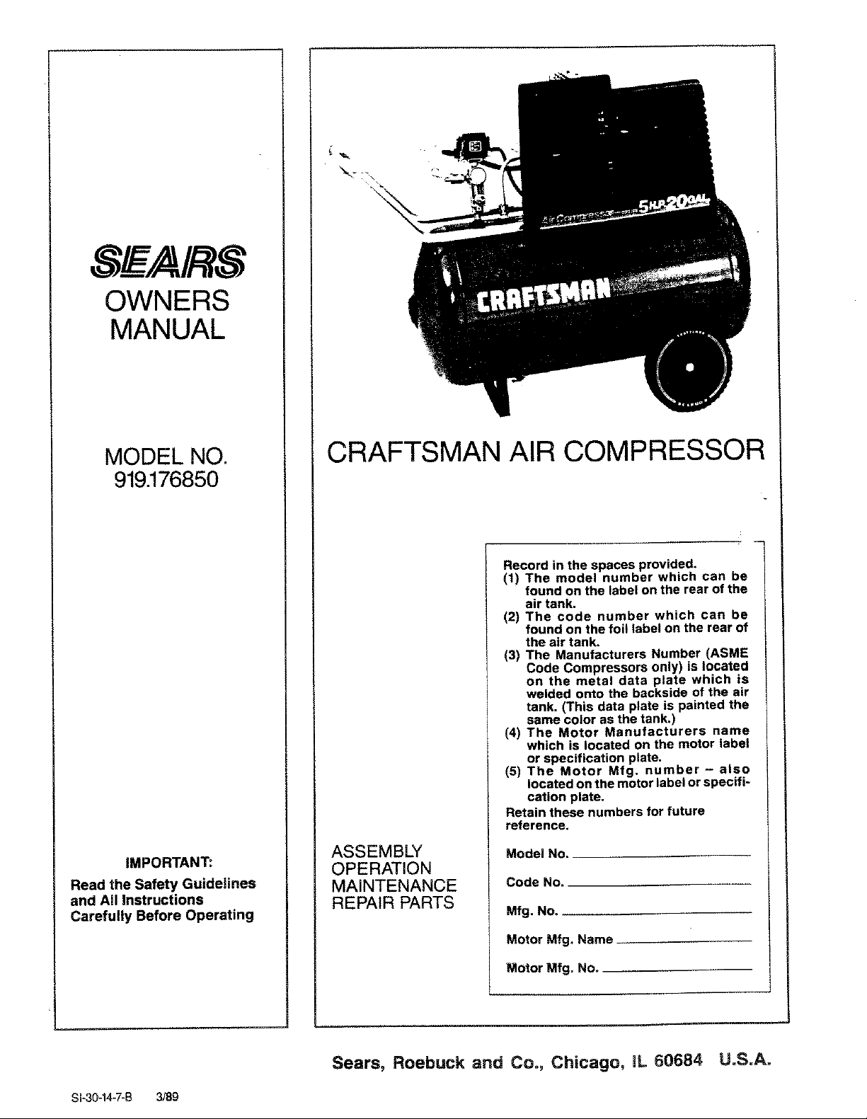
CRAFTSMAN AIR COMPRESSOR
Record in the spaces provided,
(1) The model number which can be
found on the label on the rear of the
air tank.
(2) The code number which can be
found on the foil label on the rear of
the air tank,
(3) The Manufacturers Number (ASME
Code Compressors only) is located
on the metal data plate which is
welded onto the backside of the air
tank. (This data plate is painted the
same color as the tank.)
(4) The Motor Manufacturers name
which is located on the motor label
or specification plate.
(5) The Motor Mfg. number - also
located on the motor label or specifi-
cation plate.
Retain these numbers for future
reference,
ASSEMBLY
OPERATION
MAINTENANCE
REPAIR PARTS
Model No,
Code No.
Mfg. No. __
81-30-14-7-B 3/89
Motor Mfg, Name
Motor Mfg. No.
Sears, Roebuck and Co., Chicago, IL 60684 U.S.A.
TABLE OF CONTENTS
Page
WARRANTY .................................................................. 3
SAFETY GUIDELINES ....................................................... 3
WARNING CHART ........................................................... 3
SPECIFICATION CHART ..................................................... 5
GLOSSARY .................................................................. 5
ACCESSORIES FOR USE WiTH SEARS AIR COMPRESSORS ........... 6
GENERAL INFORMATION ................................................... 6
DESCRIPTION OF OPERATION ............................................. 6
ASSEMBLY INSTRUCTIONS ................................................. 7
Items You Wil! Need to Assembly Your Compressor ............................... 7
Installing Handle ............................................................. 7
Installing Rubber Foot Strip and Wheels ......................................... 8
Installing Shut-Off Valve ...................................................... 8
INSTALLATION AND BREAK-IN PROCEDURES ............................ 8
Location of Air Compressor .................................................... 8
Extension Cords ............................................................. 8
Lubrication and Oil ........................................................... 8
Grounding Instructions ........................................................ 9
Break-in Procedures ......................................................... 9
OPERATING PROCEDURES ................................................ 9
MAINTENANCE .............................................................. 10
Air Filter - Inspection and Replacement ......................................... 10
Oil - Checking and Changing .................................................. 10
Air Tank - Draining Water ..................................................... 10
Check Valve - Replacement ................................................... 10
Safety Valve - Inspection ..................................................... 10
Motor ...................................................................... 10
Belt - Replacement ........................................................... 11
To Adjust Belt Tension ........................................................ 11
Pulley and Flywheel - Alignment ............................................... 1!
STORAGE ......................................................... 11
TROUBLESHOOTING GUIDE ................................................ 11
AIR COMPRESSOR DIAGRAM -AIt Models ................................ 14
Parts List ................................................................... 17
AIR COMPRESSOR PUMP DIAGRAM =. ................................... 15
Parts List ................................................................... 17
HOW TO ORDER REPAIR PARTS ........................................... 18
FULL ONE YEAR WARRANTY
ON AIR COMPRESSORS
If this air compressor fails due to a defect in material or workmanship within one year from the date of
purchase, return itto the nearest Sears Service Center/Department throughout the United States and
Sears will repair it,free of charge.
If this air compressor is used for commercial or rental purposes, the warranty will apply for ninety days
from the date of purchase.
This warranty gives you specific legal rights and you may have other rights that vary from state to
state.
Sears, Roebuck and Co., Sears Tower, Dept. 698/7131 CR-W, Chicago, IL 60684
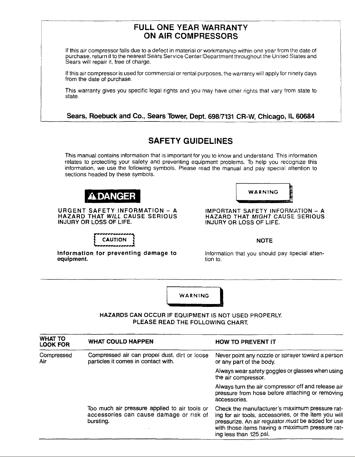
SAFETY GUIDELINES
This manual contains information that is important for you to know and understand. This information
relates to protecting your safety and preventing equipment problems. To help you recognize this
information, we use the following symbols. Please read the manual and pay special attention to
sections headed by these symbols.
URGENT SAFETY INFORMATION - A
HAZARD THAT WILL CAUSE SERIOUS
INJURY OR LOSS OF LIFE.
Information for preventing damage to
equipment.
WARNING
HAZARDS CAN OCCUR IF EQUIPMENT IS NOT USED PROPERLY,
PLEASE READ THE FOLLOWING CHART.
WHAT TO WHAT COULD HAPPEN HOW TO PREVENT IT
LOOK FOR
Compressed
Air
Compressed air can propel dust, dirt or loose
particles it comes in contact with.
Too much air pressure applied to air tools or
accessories can cause damage or risk of
bursting.
IMPORTANT SAFETY INFORMATION - A
HAZARD THAT MIGHT CAUSE SERIOUS
INJURY OR LOSS OF LIFE.
NOTE
Information that you should pay special atten-
tion to.
Never point any nozzle or sprayer toward a person
or any part of the body.
Always wear safety goggles or glasses when using
the air compressor.
Always turn the air compressor off and release air
pressure from hose before attaching or removing
accessories.
Check the manufacturer's maximum pressure rat-
ing for air tools, accessories, or the item you wil!
pressurize. An air regulator must be added for use
with those items having a maximum pressure rat-
ing tess than 125 psL
m_ .....
WHAT TO
LOOK FOR
Unsuita6te
S_vents"
Electricity
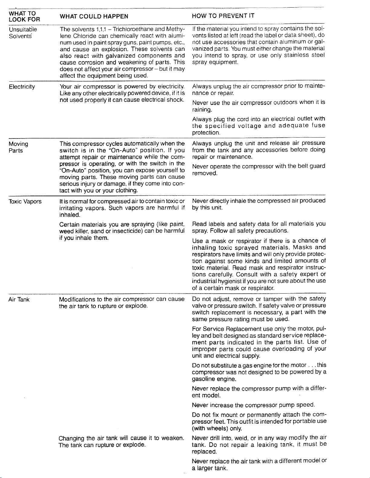
WHAT COULD HAPPEN HOW TO PREVENT IT
The solvents 1,1,1- Trichloroethane and Methy-
lene Chloride can chemically react with aiumi-
num used in paint spray guns, paint pumps, etc.,
and cause an explosion. These solvents can
also react with galvanized components and
cause corrosion and weakening of parts. This
If the material you intend to spray contains the sol-
vents listed at left (read the label or data sheet), do
not use accessories that contain aluminum or gal-
vanized parts. You must either change the material
you intend to spray, or use only stainless steel
spray equipment.
does not affect your air compressor- but it may
affect the equipment being used.
Your air compressor is powered by electricity.
Like any other electrically powered device, if it is
not used properly it can cause electrical shock.
Always unplug the air compressor prior to mainte-
nance or repair.
Never use the air compressor outdoors when it is
raining.
Always plug the cord into an electrical outlet with
the specified voltage and adequate fuse
protection.
Moving
Parts
Toxic Vapors
Air Tank
This compressor cycles automatically when the
switch is in the "On-Auto" position. If you
attempt repair or maintenance while the com-
pressor is operating, or with the switch in the
"On-Auto" position, you can expose yourself to
moving parts. These moving parts can cause
serious injury or damage, if they come into con-
tact with you or your clothing.
Itis normal for compressed air to contain toxic or
irritating vapors. Such vapors are harmful if
inhaled.
Certain materials you are spraying (like paint,
weed killer, sand or insecticide) can be harmful
if you inhale them.
Modifications to the air compressor can cause
the air tank to rupture or explode.
Always unplug the unit and release air pressure
from the tank and any accessories before doing
repair or maintenance.
Never operate the compressor with the belt guard
removed.
Never directly inhale the compressed air produced
by this unit.
Read labels and safety data for all materials you
spray. Follow al! safety precautions.
Use a mask or respirator if there is a chance of
inhaling toxic sprayed materials. Masks and
respirators have limits and will only provide protec-
tion against some kinds and limited amounts of
toxic material. Read mask and respirator instruc-
tions carefully. Consult with a safety expert or
industrial hygienist if you are not sure about the use
of a certain mask or respirator.
Do not adjust, remove or tamper with the safety
valve or pressure switch. Ifsafety valve or pressure
switch replacement is necessary, a part with the
same pressure rating must be used.
For Service Replacement use only the motor, pul-
ley and belt designed as standard service replace-
ment parts indicated in the parts list. Use of
improper parts could cause overloading of your
unit and electrical supply.
Do not substitute a gas engine for the motor.., this
compressor was not designed to be powered by a
gasoline engine.
Never replace the compressor pump with a differ-
ent model.
Changing the air tank will cause it to weaken.
The tank can rupture or explode.
Never increase the compressor pump speed.
Do not fix mount or permanently attach the com-
pressor feet. This outfit is intended for portable use
(with wheels) only.
Never drill into, weld, or in any way modify the air
tank. Do not repair a leaking tank, it must be
replaced.
Never replace the air tank with a different model or
a larger tank.
WHAT TO WHAT COULD HAPPEN HOW TO PREVENT IT
LOOK FOR
Hot Parts The compressor head and tubes get hot when Never touch the air compressor head or tubes dur-
the air compressor is running. If you touch them, ing or immediately after operation.
you can be seriously burned.
Flammable It is normal for the motor and pressure switch to Operate the compressor in well ventilated areas
Vapors spark when the compressor starts or stops. A that are free of gasoline, flammable paint or solvent
spark can ignite flammable vapors from vapors.
gasoline, solvents or some paints and cause a If spraying a flammable material - provide ample
fire or explosion.
ventilation. Never spray in a closed area. There
must be a flow of fresh air at all times.
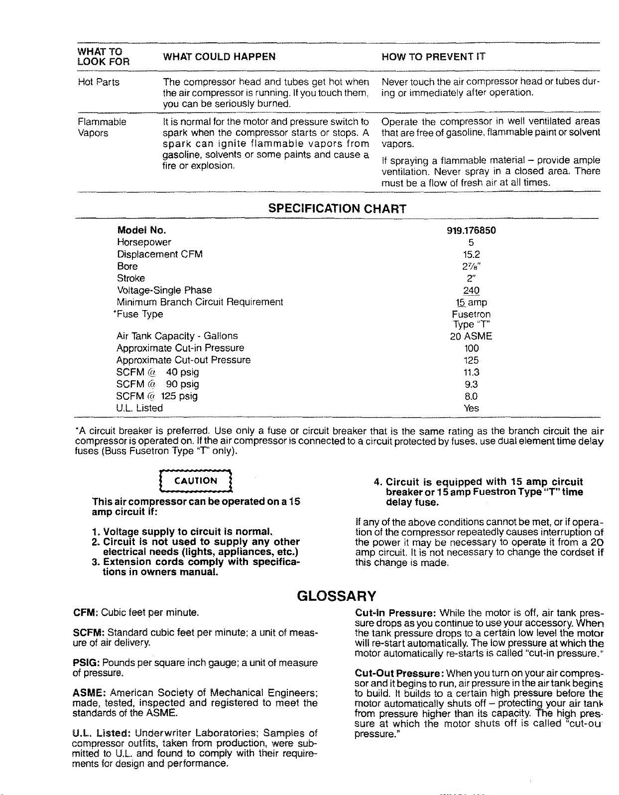
SPECIFICATION CHART
Model No. 919.176850
Horsepower 5
Displacement CFM 15.2
Bore 27/8"
Stroke 2"
Voltage-Single Phase 240
Minimum Branch Circuit Requirement 1_ amp
*Fuse Type Fusetron
Type "T"
Air Tank Capacity - Gallons 20 ASME
Approximate Cut-in Pressure 100
Approximate Cut-out Pressure 125
SCFM _ 40 psig 11.3
SCFM (_ 90 psig 9.3
SCFM #! 125 psig 8.0
U,L. Listed Yes
*A circuit breaker is preferred. Use only a fuse or circuit breaker that is the same rating as the branch circuit the air
compressor is operated on. Ifthe air compressor is connected to a circuit protected by fuses, use dual element time delay
fuses (Buss Fusetron Type "T" only).
4. Circuit is equipped with 15 amp circuit
breaker or 15 amp Fuestron Type "T" time
This air compressor can be operated on a 15
amp circuit if:
1. Voltage supply to circuit is normal.
2. Circuit is not used to supply any other
electrical needs (lights, appliances, etc.)
3. Extension cords comply with specifica-
tions in owners manual.
tion of the compressor repeatedly causes interruption of
the power it may be necessary to operate it from a 20
amp circuit. It is not necessary to change the cordset if
this change is made.
delay fuse.
Ifany of the above conditions cannot be met, or ifopera-
GLOSSARY
CFM."Cubic feet per minute.
SCFM: Standard cubic feet per minute; a unit of meas-
ure of air delivery.
PSIG."Pounds per square inch gauge; a unit of measure
of pressure.
ASME: American Society of Mechanical Engineers;
made, tested, inspected and registered to meet the
standards of the ASME.
U.L. Listed: Underwriter Laboratories; Samples of
compressor outfits, taken from production, were sub =
mitted to U.L. and found to comply with their require-
ments for design and performance,
Cut-In Pressure: While the motor is off, air tank pres-
sure drops as you continue to use your accessory. When
the tank pressure drops to a certain low level the motor
will re-start automatically. The low pressure at which the
motor automatically re-starts is called "cut-in pressure."
Cut-Out Pressure: When you turn on your air compres-
sor and it begins to run, air pressure inthe air tank begins
to build. It builds to a certain high pressure before the
motor automatically shuts off - protecting your air tank
from pressure higher than its capacity. The high pres.
sure at which the motor shuts off is caUed "cut-ou
pressure."
ACCESSORIES FOR USE WITH SEARS AIR COMPRESSORS
Tile following accessories are available through the current general sales catalog or at full-line Sears stores.
*SPRAY GUNS
.BLOW GUNS
-AIR CAULKING GUNS
,AIR POWERED WASHER GUNS
-SAND BLASTERS
,AIR BRUSHES
-AIR LINE FILTERS
*TIRE AIR CHUCKS
-PAINT TANKS
*AIR TANKS
*INFLATOR KITS
.QUICK CONNECTOR SETS
(various sizes)
oVISCOSIMETER
*AIR PRESSURE REGULATORS
*OIL FOG LUBRICATORS
*AIR TOOLS:
Sanders
Drills
Impact wrenches
Hammers
,AIR HOSE:
1/4", 5/16" OR 3/8" LD.
in various lengths.
GENERAL INFORMATION
_'ouhave purchased an air compressor unit consisting of
a 2 cylinder, single stage air compressor pump, an air
:ank, air hose, wheels, handle, air chuck and associated
:ontrols and instruments.
Your air compressor can be used for operating paint
spray guns, air tools, caulking guns, grease guns, air
3rushes, sandblasters, power washers, inflating tires
and plastic toys, spraying weed killers, insecticides, etc.
Fhis model is not equipped with a pressure regulator. An
_ir pressure regulator is usually necessary for most of
:hese applications. An Air Line Filter is usually required
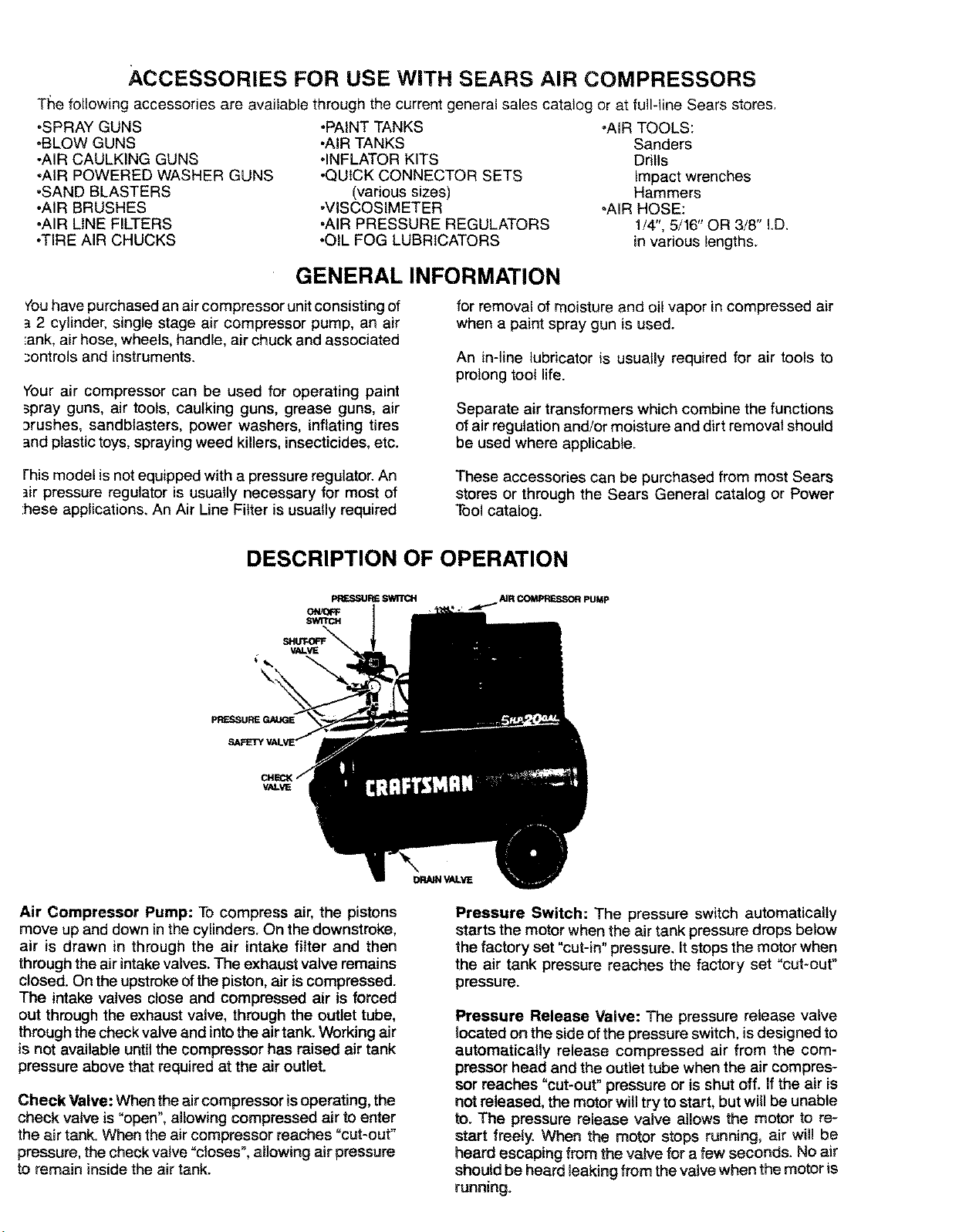
DESCRIPTION OF OPERATION
V/eVE
\
for removal of moisture and oil vapor in compressed air
when a paint spray gun is used.
An in-line lubricator is usually required for air tools to
prolong toot life.
Separate air transformers which combine the functions
of air regulation and/or moisture and dirt removal should
be used where applicable.
These accessories can be purchased from most Sears
stores or through the Sears General catalog or Power
Tool catalog.
Air Compressor Pump: To compress air, the pistons
move up and down in the cylinders. On the downstroke,
air is drawn in through the air intake filter and then
through the air intake valves. The exhaust valve remains
closed. On the upstroke of the piston, air is compressed.
The intake valves close and compressed air is forced
out through the exhaust valve, through the outlet tube,
through the check valve and into the air tank. Working air
is not available until the compressor has raised air tank
pressure above that required at the air outlet.
Check Valve: When the air compressor isoperating, the
check valve is "open", allowing compressed air to enter
the air tank. When the air compressor reaches "cut-out"
pressure, the check valve "c!oses", allowing air pressure
to remain inside the air tank.
Pressure Switch: The pressure switch automatically
starts the motor when the air tank pressure drops below
the factory set "cut-in" pressure. It stops the motor when
the air tank pressure reaches the factory set "cut-out"
pressure.
Pressure Release Valve: The pressure release valve
located on the side ofthe pressure switch, is designed to
automatically release compressed air from the com-
pressor head and the outlet tube when the air compres-
sor reaches "cut-out" pressure or is shut off. If the air is
not released, the motor willtry to start, but wil be unable
to. The pressure release valve allows the motor to re-
start freely. When the motor stops running, air will be
heard escaping from the valve for a few seconds. No air
should be heard leaking from the valve when the motor is
running.
 Loading...