

Page 1

ISears]
OWNERS
MANUAL
MODEL NOS.
919.174212
919.174311
919.174320
919.174410
AiR
COMPRESSOR
iMPORTANT:
Read the Safety
Guidelines Before
Operating
DESCRIPTION
ASSEMBLY
OPERATION
MAINTENANCE
REPAIR PARTS
Record in the spaces provided
below the model number, code
number and manufacturers hum=
bet of this air compressor. The
model number can be found on
the label on the front of the air
tank. The code number can be
found on the for label on the rear
of the air tank. The manufacturers
number (ASIVlE Code outfits only)
is located on the metal data plate
on the backside of the air tank.
Model No.
Code No.
Mfgs. No.
Motor Mfg. Name
Motor Mfg. No.
Retain these numbers for future
references.
SI-30-14-2-A
Sears, Roebuck and Co., Chicago, IL 60684 U.S.A.
% % %
2!85
Page 2
TABLE OF CONTENTS
WARRANTY ....................................................... 3
SAFETY GUIDELINES .............................................. 3
SPECIFICATION CHART ............................................ 5
GENERAL INFORMATION .......................................... 6
GENERAL DESCRIPTION OF OPERATION ........................... 6
ASSEMBLY INSTRUCTIONS ........................................ 6
Tools Needed for Assembly ...................................... 6
Attaching Wheels, Handle, Etc.................................... 6
installing Regulator ............................................. 7
Start-Up Procedures ............................................ 7
OPERATION ....................................................... 7
Manifold ....................................................... 7
Pressure Switch ................................................ 7
Safety Valve ................................................... 8
Motor ......................................................... 8
Pressure Release Valve ......................................... 8
MAINTENANCE .................................................... 8
Replacing Air Intake Filter ....................................... 8
Checking Safety Valve .......................................... 8
Checking and Changing Oil ...................................... 8
Location of Air Compressor ...................................... 9
Draining Water From Air Tank ................................... 9
Replacing Belt .................................................. 9
AIR COMPRESSOR DIAGRAM ...................................... 10
PARTS LIST 11
ACCESSORIES ................................................... 13
TROUBLESHOOTING GUIDE ............................................... 14
HOW TO ORDER REPAIR PARTS ........................................ 16
Page 3

FULL ONE YEAR WARRANTY
AIR COMPRESSOR
if this compressor fails due to a defect in material or workmanship within one year from the
date of purchase, return it to the nearest Sears Service Center/Department throughout the
United States and Sears will repair it, free of charge.
if this air compressor is used for commercial or rental purposes, the warranty will apply for
ninety days from date of purchase.
This warranty gives you specific legal rights and you may also have other rights which vary
from state to state.
Sears, Roebuck and Co., Sears Tower, Dept. 698/731A, Chicago, IL 60684
SAFETY GUIDELINES
This manual contains information that is important for you to know and understand.
This information relates to YOUR SAFETY and PREVENTING EQUIPMENT PROBLEMS.
To help you recognize this information, we use the following symbols. Please read the manual and
pay attention to those sections.
iMPORTANT iNFORMATiON FOR PRE-
VENTmNG mNJURY OR LOSS OF LIFE.
information for preventing damage to
equipment.
Note
information that you should pay special atten-
tion to.
Page 4

PLEASE READ THE FOLLOWmNG CHART.
AREA
indicateswhere a hazard
can occur.
Moving Parts
Flammable vapors
Hot Parts
Air Tank
HAZARD
Indicateswhat can happen if pre-
cautions are not observed.
Loose items,or parts of the body
may get caught and cause serious
injuryor damage.
Unit cycles automatically when
power is ON. During service or
repair activities, this automatic
cycling may cause a hazard.
A spark from the motor or pressure
switch electrical contacts can ignite
flammable vapors from gasoline or
solvents, and cause an explosion
or fire.
Air compressors get hot when run-
ning. Serious burns may resuk if
touched.
Air pressure or mechanical loads
that are higher than design loads
may cause the tank to rupture.
SAFEGUARDS
indicates how to avoid the hazard and what
special protectiveclothing, equipment, and pre-
cautions will be used.
Never operate the compressor with the belt
guard removed.
Keep small children, your hands, and all items
away from the flywheel and belt.
Always unplugthe unit before attempting repair
or maintenance of the compressor. Also, make
sure the pressure is released from the com-
pressor and air tank.
The compressor and any other electrical tool
must only be used in well ventilated areas, free
of gasoline or solvent vapors.
Never touch the compressor, tubing, or motor
during or immediately after operation of the
compressor.
Do not adjust, remove, or defeat the safety
valve. Check the valve from time to time by pul-
ling the ring on the valve. If the valve is stuck or
does not operate smoothly, it must be replaced.
Electrical Shock
Do not adjust, remove, or defeat the pressure
switch.
Never use a motor with higher horsepower rat-
ing than the one supplied.
The compressor was not designed to be
powered by a gasoline engine. Do not substi-
tute a gas engine.
Changes to the air tank structure
will cause the tank to weaken. Tank
Never drill into, weld, or change the tank in any
way.
rupture or explosion may occur.
This unit is powered by 120 or 240 Always unplug unit prior to doing any main-
volts, tenance or repair.
Never use the unit outdoors when it is raining.
Always plug the cord into an electrical outlet
with the specified voltage and adequate fuse
protection.
4
Page 5

AREA HAZARD SAFEGUARDS
Use of unsuitable solvents
Toxic Vapors
Compressed Air
The solvents 1,1,1-Trichlorethane
and Methylene Chloride can
chemically react with aluminum
used in paint spray guns, paint
pumps, etc. and cause an explo-
sion. These solvents can also
react with galvanized compo-
nents and cause corrosion and
weakening of parts.
Compressed air from this unit
may contain poisonous carbon
monoxide.
Certain sprayed materials such
as paints, weed killer, sand,
insecticides, etc., may be harmful
if used in a closed area or if
inhaled.
Compressed air may propel dirt,
metal shavings, etc. and result in
possible injury.
This hazard does not affect your compressor
outfit - but it may affect the equipment used
with the outfit. Read the label or data sheet
for the material you intend to spray. Equip-
ment containing aluminum or galvanized
parts that will come in contact with these sol-
vents, and that can contain pressure, must
not be used with these solvents. You must
either change the material, or use only
stainless steel spray equipment.
Never directly inhale the compressed air pro-
duced by this unit.
Be certain to read labels when spraying
paints or poisons.
Use a mask or respirator whenever there is a
chance that you might inhale anything that
you are spraying. Read all instructions so
that you know that your mask will protect you
from what you are spraying.
Never point any nozzle or sprayer toward a
person or any part of the body.
Always wear safety goggles orglasses when
spraying.
SPECIFICATION CHART
Model No. 919.174212 919.174311 919.174410 919.174320
HP 1 1 1 2
Displacement CFM 8.8 8.8 8.8 9.2
Bore 23/4" 23/4" 23/4'' 23/4''
Stroke 2" 2" 2" 2"
Voltage-Single Phase 1!0-120 110-120 !10-120 220-240
Minimum Branch Circuit Requirement 20 amp 20 amp 20 amp 15 amp
*Fuse Type "Fusetron" Type T "Fusetron" Type T "Fusetron" Type T "Fusetron" Type T
Amperage at Max. Pressure 18.2 18.2 18.2 9.9
Air Tank Capacity 12 gal. 12 gal. (ASME) !2 gal. (ASME) 20 gal. (ASME)
Approximate Cut-in Pressure 75 psig 75 psig 80 psig 80 psig
Approximate Cut-out Pressure 100psig 100 psig 100 psig 100 psig
SCFM at 100 psig 5.1 5.1 5.1 5.6
SCFM at 90 psig 5.3 5.3 5.3 6.1
SCFM at 40 psig 6.6 6.6 6.6 Z5
SCFM (Standard Cubic Feet per Minute): Unit of measure of air delivery.
SLM (Standard Liters per Minute): Metric unit of measure of air delivery.
PSIG (Pounds per Square Inch Gauge): Unit of measure of pressure.
kPa (Kilo Pascals): Metric unit of measure of pressure.
*A circuit breaker is acceptable.
5
Page 6

THIS MANUAL IS DESIGNED TO MAKE iT AS EASY AS POSSIBLE
FOR YOU TO SET UP, OPERATE AND MAiNTAiN
YOUR NEW AiR COMPRESSOR
GENERAL iNFORMATiON
You have purchased a complete portable compressor
outfit consisting of a 2 cylinder single-stage air
compressor with air tank, air hose assembly, wheels
and handle. You will also find an air chuck and a
helpful "Power Painting With Sprayers" booklet. The
2 horsepower unit has a removable foot extension
bracket which allows for stationary mounting.
These units can be used for operating caulking guns,
grease guns, air brushes, sandblasters, air tools, etc., or
inflating tires and plastic toys, spraying weed killer,
insecticides, etc.
GENERAL DESCRIPTION OF OPERATION
To compress air, the pistons move up and down in the
cylinder. On the downstroke, air isdrawn in through the
air intake valve. The exhaust valve remains dosed. On
the upstroke of the piston, air iscompressed. The intake
valves close and compressed air is forced out through
the exhaust valve, through the check valve and intothe
air tank. Working air isnot available until the compressor
has raised the air tank pressure above that required at
the air outlet. The air intake opening must be kept clear
of obstructions which could reduce air delivery of the
compressor.
ASSEMBLY iNSTRUCTiONS
Tools Needed For Assembly
Tools needed are: (1) a 9/_6"socket or open end wrench
for attaching the wheels and hose adapter; and (2) an
adjustable wrench for attaching the pressure regulator,
and (3) a Z/l_"open end wrench for attaching the air
pressure gauge, (4) a 7/_6"socket or open end wrench for
attaching the foot extension bracket (2 hp. unit only), (5)
a 3/_6"hex key for installing the plug in the regulator and
(6) pipe thread sealant.
Attaching Wheels, Handle, Etc.
THE WHEELS AND HANDLE DO NOT
PROVIDE ADEQUATE CLEARANCE, STA-
BILITY OR SUPPORT FOR PULLING THE
UNiT UP OR DOWN STAIRS AND STEPS.
THE UNiT MUST BE UFTED OR PUSHED UP
A RAMP.
See diagram on page 10 for attaching air pressure
regulator (46), wheels (38), foot extension bracket (43)
and handle (47). Refer to the illustration, page 10, Key
No's. 22, 39, 40, 42, 44, 45, 84, 85 and 86.
AIR
COMPRESSOR,.
PUMP
CONNECTION
OiL FiLL
PLUG
OiL DRAIN
PLUG
AiR OUTLET
AiR iNTAKE
AND FILTER
X
ON=AUTO/OFF
SAFETY
VALVE
RESET BUTTON
REGULATOR
DRAIN COCK VALVE
(NOT SHOWN)
G
Page 7

it may be necessary to brace or support one
end of the outfit when attaching the wheels
and the foot extension bracket because the
outfit will have a tendency to tip over before
wheels are attached.
1. insert the handle into pockets under the tank base.
Put one set screw (22) through hole in one side of
tank base and tighten down on handle.
2. Remove the protective paper strip from the adhesive
backed rubber foot strip (45). Attach the rubber foot
strip to the bottom of the foot extension bracket (43)
or tank leg. Press firmly intoplace.
3. Attach foot extension bracket (43) tothe air tank brack-
et. Use one cap screw (44), one Iockwasher (87) and
one hex nut (42) at each end. Tighten. (Model
919.174320only)
4. Attach one wheel (38) to each side of the outfit. Use
one shoulder bolt (39) and one locking hex nut (40)
for each wheel. Tighten securely. Use the bracket
lower bolt hole for attaching the wheels on model
919.174320.
iNSTALLiNG REGULATOR
Install the regulator (48) on the end of the manifold
(28) using the short pipe nip#e (84). The arrow must
point away from the manifold in order for the regulator
to function properly. Next, install the gauge (85),
adapter (86) and plug in the regulator. The plug is
supplied with the regulator. (Note: Use a small
amount of pipe thread sealant on all pipe thread
joints.) Refer to Figure 2.
REGULATED
MANI- PRESSURE GAUGE
FOLD
ADAPTER
crankcase, the oil flows intoitvery slowly. If the oil is
added too quickly, it will overflow and appear to be
full. (Crankcase oil capacity is 16fluid ounces.) Under
winter-type conditions use SAE 10W oil. Multi-
viscosity oil (10W 30) may be used but will result in
carbon deposits on critical components and reduce
performance and compressor life. Replace oil fill plug
(50). Plug the compressor into the correct power
source. Start the compressor by switching the ON-
AUTO/OFF switch (20) to the ON-AUTO position.
Open the regulator (46) by turning knob clockwise
fully to permit air to escape and prevent air pressure
buildup in the air tank. RUN THE COMPRESSOR 30
MINUTES iN THiS MANNER TO LUBRICATE PIS-
TONS AND BEARINGS. Shut off air with regulator
(turn knob counterclockwise) and letthe unit pump up
to cut-off pressure. Turn the switch to "OFF" and
check the oil level; add oil ifnecessary. Turn switch to
"ON" and the unit is ready for use. Connect the air
hose to the air adapter (86) located at the end of the
regulator.Refer to Figure 1.
OPERATION
Manifold
The manifold (28) is located on the top of the unit
between the motor and air compressor pump. On the
manifold is the pressureswitch (20), safety valve (29),
regulator (46) and pressure gauge (27). The gauge
shows the air tank pressure. The air pressure coming
from the air tank is controlled by the regulator knob.
Turn the knob clockwise to increase pressure and
counterclockwise to decrease pressure. Refer to Fig-
ure 3. To avoid minor readjustment after making a
change in pressure setting, always approach the
desired pressure from a lower pressure. When reduc-
ing from a higher to a lower setting, first reduce to
some pressurelessthan that desired, then bring up to
the desired pressure. Depending on the air flow
requirements of each particular accessory, the outlet
regulated air pressure might have to be adjusted under
flow conditions.
PiPE
NIPPLE PLUG
Start-Up Procedures
All units are shipped without oil. Serious
damage may result if the following break=in
instructions are not closely followed. This
operation has to be completed only once
when first putting the unit in service.
Place unit on a level surface. Remove oil fill plug (50)
and slowly add a special compressor oil such as
Sears 9-16426 or SAE 20-20W SF motor oil until it is
even with the top of the oil fill hole. When filling the
Pressure Switch
PRESSURE LOADS BEYOND DESIGN L_MITS
MAY CAUSE TANK RUPTURE OR EXPLOSION.
PRESSURE SW_TCH OPERATION IS RELATED
TO MOTOR HP, TANK RATmNG AND SAFETY
VALVE SETTING° DO NOT ATTEMPT TO
ADJUST, REMOVE, OR DEFEAT THE PRESo
SURE SWmTCH, OR CHANGE AND MODIFY ANY
PRESSURE CONTROL RELATED DEWCE.
The pressure switch (20) starts the motor when the air
tank pressure drops below the factory set cut-in pres-
sure and stops the motor when the air tank pressure
reaches the factory set cut-off pressure. (See specifica-
tion chart, page 5.)
7
Page 8

Safety Valve
OVER°PRESSURmZATmON OF THE AiR
TANK MAY CAUSE TANK RUPTURE OR
EXPLOSmONo THE OUTFmT mSPROTECTED
FROM THE OVERoPRESSURJZATION BY A
SAFETY VALVE. DO NOT ELIMINATE,
MAKE ADJUSTMENTS OR SUBSTiTU-
TiONS TO THiS DEVICE.
Note
Avoid using long extension cords. They can
cause a power loss to the motor. Add extra air
hose instead of extension cords.
If an extension cord must be used, follow the recom-
mendations listed below using a 3-wire extension cord.
Cord Length Minimum Wire Size
0-50 Feet 12 gauge
TANK
Figure 3
The pressure switch (20) is pre-set to shut off the motor
automatically at the maximum operating pressure. If the
pressure switch does not shut off the outfit at its cut-off
pressure setting, the safety valve will protect against
high pressure by popping at its pre-set pressure.
Motor
Pressure Release Valve
{Models 919.174410 & 919.174320 Only)
The pressure release valve located on the bottom of the
pressure switch is designed to unload air from the com-
pressor head automatically at unit shut off. This protects
the motor from starting against air pressure remaining in
the compressor head and tubing. When the motor stops
running, air will be heard escaping from the valve for a
few seconds. When the motor is running, no air should
be leaking from the pressure release valve.
Note
Models 919.174212& 919.174311are designed to
operate withoutthis unloading feature.
MAINTENANCE
Replacing Air intake Filter
A dirty air intake filter will not allow the compressor to
operate at full capacity. When the intake filter becomes
dirty, oily, or covered with paint overspray, replace it. Do
not operate the compressor with the air intake filter
removed. To replace the filter, use needle nosed pliers
and pull or pry the old filter out. Replace with new. Refer
to Figure 1.
The motor has a thermal overload protector, tfthe motor
overheats for any reason, the overload protector will
shut off the motor. The motor must be allowed to cool
before restarting. Turn the ON-AUTO/OFF switch to the
OFF position. To restart, turn the ON-AUTO/OFF switch
to the ON position. Depress the reset button located on
the end of the motor. Refer to Figure 1.
Note
If the overload protector shuts the motor off
frequently, check for a possible voltage prob-
lem. Low voltage can also be suspected when:
1. The motor does not get up to full power or
speed.
2. Fuses blow out when starting motor.
3. Lights dim and remain dim when motor is
started.
8
Checking Safety Valve
OVER-PRESSUR_ZATmON CAUSING TANK
RUPTURE OR EXPLOSmON MAY OCCUR JF
THE SAFETY VALVE DOES NOT WORK
PROPERLY. OCCASIONALLY PULL THE
R_NG ON THE SAFETY VALVE TO MAKE
SURE THAT THE VALVE OPERATES
FREELY, mFTHE VALVE IS STUCK OR DOES
NOT OPERATE SMOOTHLY, IT MUST BE
REPLACED.
Checking and Changing Oil
Overfilling with oil will cause premature
compressor failure. Do not overfill.
Page 9

Checkoillevelinthecrankcasebeforeeachuse.Theoil
levelshouldbeevenwiththetopofthefirlholeandmust
notbeallowedtobelowerthan3/8"fromthetopatany
time.itis recommendedthattheoilinthebase(51)be
changedafterevery100hoursofoperation.Todrainthe
oil,removetheoildrainplug(50)andcollecttheoilina
suitablecontainer.Besuretoreplacetheplugsecurely
beforeaddingnewoil.UseaspecialcompressoroiJ,such
asSears9-16426orSAE20-20WSFmotoroil(crank-
caseoilcapacityis16fluidounces).Underextremewin-
terconditionsuse10weightoil.
Location of Air Compressor
Replacing Belt
SERIOUS INJURY OR DAMAGE MAY
OCCUR mFPARTS OF THE BODY OR LOOSE
ITEMS GET CAUGHT mN MOVmNG PARTS.
NEVER OPERATE THE OUTFmT WITH THE
BELT GUARD REMOVED. THE BELT
GUARD SHOULD BE REMOVED ONLY
WHEN THE POWER CORD JS
DISCONNECTED.
Locate the unit in a dry, clean, cool and well ventilated
area. The compressor crankcase and head are designed
with fins which allow for proper cooling. Clean or blow off
fins and any other parts of the compressor that collect
dust or dirt. A dean compressor runs cooler and provides
longer service. Do not place rags, containers or other
matedal on or against the belt guard which wouJd obstruct
ventilation openings necessary for proper compressor
operating temperature, ffhumidity is high, a Sears air filter
can be used to remove excessive moisture. Follow the
instructions packaged with the air filter for proper
installation.
Draining Water From Air Tank
[
/ WARNING
WATER WmLL CONDENSE mN THE AmR
TANK. IF NOT DRAmNED, THE WATER W_LL
CORRODE AND WEAKEN THE TANK.
DRAIN THE TANK AS iNSTRUCTED
BELOW.
Water should be drained from the air tank weekly depend-
ing on where and how often the outfit has been used. If
humidity is high, drain more often. To drain the water that
has gathered in the air tank, open drain cock valve (41,
page 10) and allow to drain. When empty, close the valve
tightly before operating the compressor.
The motor is mounted on an adjustable motor base. By
looseningthe wing nut (25), the motor can be tilted in to
allow for easy tightening or removal of the belt (73).
To replace belt:
1. Unplug unit from power source before repairing.
2. Remove screws (1) from the back of the belt guard.
Remove belt guard (2).
3. Loosen wing nut (25) and tilt motor in.
4. Remove belt and replace with new.
Note
The belt should be centered over the grooves
on the flywheel and motor pulley.
5_
Push the motor back into regular position and tighten
wing nut securely by hand. Proper tension is approx-
imately 1/4"belt deflection measured midway be-
tween the pulley and flywheel when a 3 pound weight
or equivalent finger pressure is applied at this point.
A loose belt will squeal at unit start-up.
6. Replace belt guard (2) and screws (1).
Note
if drain cock valve is clogged, release air
pressure in the air tank and then remove.
Clean and reinstall the valve.
9
Page 10

Air Compressor
1
jl
65_t_ _ 65
<L _63
,L_..9'
4d
73
78 /
79
"_ C_--s9
21
58_
82
7t
| a_ss
/
/
80
b3 30'_I
32
48-I i50
//35
74
!
10
47
<, <
41
40
38,
Page 11

KEY
NO. PART NUMBER
PARTS LIST
DESCRiPTiON
1 SSF-953-ZN
2 CAC-22
3 CAC-142
4 SSF-6627
5 CAC-2
6 SSF-8113-ZN
7 265-18
8 LA-1575
9 SSF-935
* 10 9-16279
11 SS-8553
11A SS-1215
12 STD575025
STD575026
13 CAC-190
14 SSF-955
15 SSP=9401
16 STD575050
STD575051
17 CAC-137
18 CAC-437
19 CAC-472
CAC-438
SUDL-404-1
20 CAC-462
CAC-496
21 SUDL-402-2
CAC-497
21A CAC-203
22 SS-391
23 PU-2859
C-PU-2833
24 STD580104
25 STD541631
26 MO-6026-P
MO-6223-P
27 C-GA-332
28 CAC-226
29 TIA=4125
TIA-4325
30 SS-2109
31 SSF-8086
32 Not available
LA=1709
33 SSW-8214
34 SUDL-59
35 SUDL-54
Self tapping screw (8 used)
Belt guard
Belt guard closure
Stud
Bracket
Lock nut
Filter retainer
Label
Screw #8-32 x %" (2 used)
Kit of two intake filters (1 used)
Connector body (Models 919.174410& 919.174320)
1/a"NPT pipe plug (Models 919.174212& 919.174311)
1/4"Nut (2 used) (Models 919.174410& 919.174320)
%" Ferrule (2 used) (Models 919.174410& 919.174320)
Pressure release tube (Models 919.174410& 919.174320)
Screw 3/8-16x 11/2"(5 used)
Connector body
1/2"Nut (2 used)
1/2"Ferrule (2 used)
Outlet tube
Check valve
Cord assembly (Models 919.174212& 919.174311)
Cord assembly (Model 919.174410)
Cord assembly (Model 919.174320)
Pressure switch (Models 919.174410& 919.174320)
Pressure switch - not shown (Models 919.174212& 919.174311)
Cord assembly (motor to pressure switch) (Models 919.174410& 919.174320)
Cord assembly (motor to pressure switch) (Models 919.174212& 919.174311)
Grounding Clip - not shown (2 used) (Models 919.174212& 919.174311)
Set screw (2 used)
Motor pulley (Models 919.174212,919.174311& 919.174410)
Motor pulley (Model 919.174320)
Key, 3/16"X 3/le"X 11/4"
Wing nut
Motor 1-HP (Models 919.174212,919.174311& 919.174410)
Motor 2-HP (Model 919.174320)
Gauge (1/4"NPT)
Manifold
Safety valve (ASME) (Models 919.174311,919.174320& 919.174410)
Safety valve (Model 919.174212)
Nipple
Speed nut
U.L. label (Model 919.174410)
Label (Models 919.174311& 919.174320)
Cord clamp
Hold down screw
Pin
See page 13for parts ordering information.
11
Page 12
KEY
NO. PART NUMBER
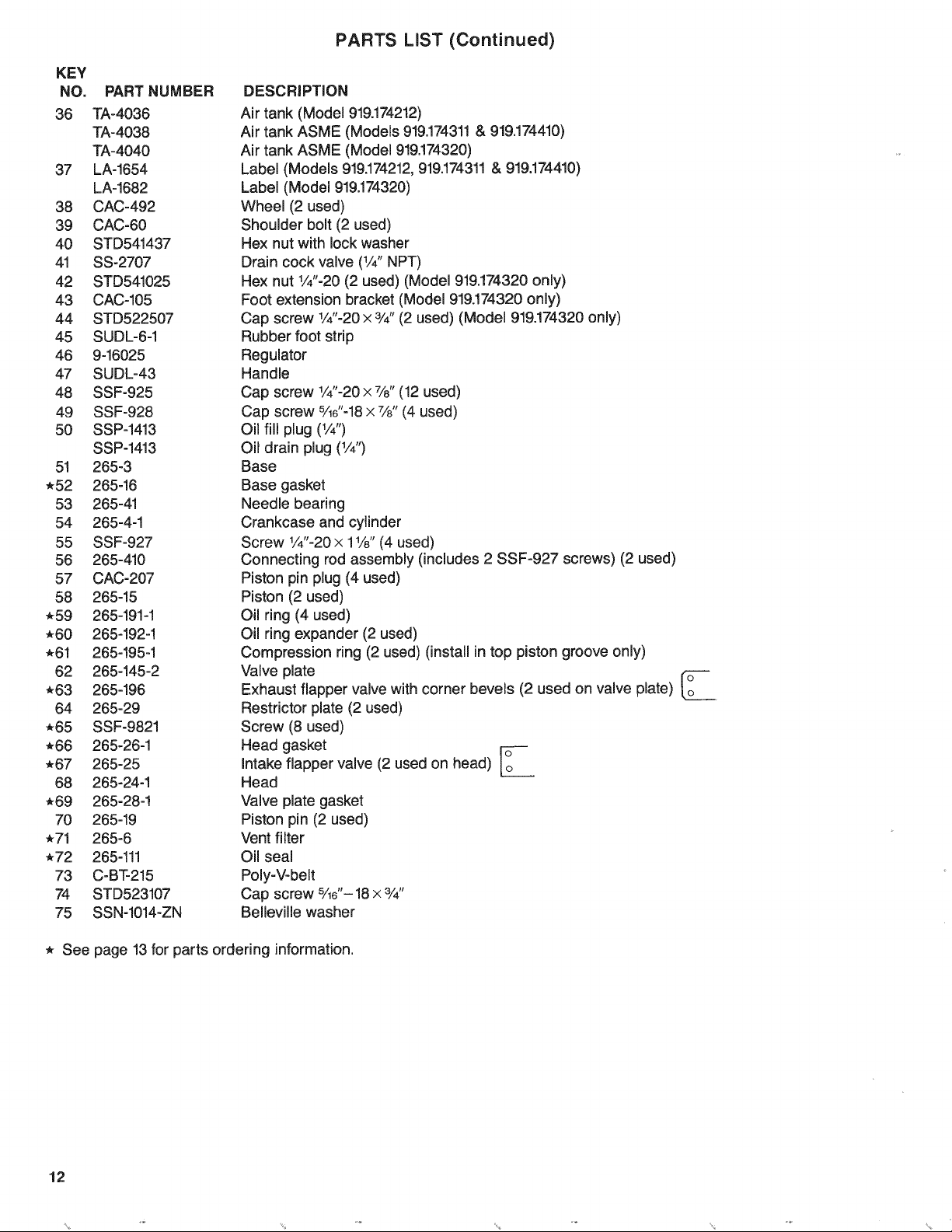
36 TA-4036
TA-4038
TA-4040
37 LA-1654
LA-1682
38 CAC-492
39 CAC-60
40 STD541437
41 SS-2707
42 STD541025
43 CAC-105
44 STD522507
45 SUDL-6-1
46 9-16025
47 SUDL-43
48 SSF-925
49 SSF-928
50 SSP-1413
SSP-1413
51 265-3
*52 265-16
53 265-41
54 265-4-1
55 SSF-927
56 265-410
57 CAC-207
58 265-15
*59 265-191-1
*60 265-192-!
-61 265-!95-1
62 265-145-2
*63 265-196
64 265-29
*65 SSF-9821
*66 265-26-1
*67 265-25
68 265-24-1
*69 265-28-!
70 265-19
-71 265-6
*72 265-111
73 C-BT-215
74 STD523107
75 SSN-1014-ZN
PARTS LiST (Continued)
DESCRiPTiON
Air tank (Model 919.174212)
Air tank ASME (Models 919.174311& 919.174410)
Air tank ASME (Model 919.174320)
Label (Models 919.174212,919.174311& 919.174410)
Label (Model 919.174320)
Wheel (2 used)
Shoulder bolt (2 used)
Hex nut with lock washer
Drain cock valve (1/4"NPT)
Hex nut 1/4"-20(2 used) (Model 919.174320 only)
Foot extension bracket (Model 919.174320only)
Cap screw 1/4"-20x 3/4"(2 used) (Model 919.174320 only)
Rubber foot strip
Regulator
Handle
Cap screw 1/4"-20x 7/8"(12 used)
Cap screw %6"-18x 7/8"(4 used)
Oil fill plug (1/4")
Oil drain plug (1/4")
Base
Base gasket
Needle bearing
Crankcase and cylinder
Screw 1/4"-20x 11/8"(4 used)
Connecting rod assembly (includes 2 SSF-927 screws) (2 used)
Piston pin plug (4 used)
Piston (2 used)
Oil ring (4 used)
Oil ring expander (2 used)
Compression ring (2 used) (install in top piston groove only)
Valve plate
Exhaust flapper valve with corner bevels (2 used on valve plate)
Restrictor plate (2 used)
Screw (8 used)
Head gasket Io
intake flapper valve (2 used on head) Io
Head
Valve plate gasket
Piston pin (2 used)
Vent filter
Oil seal
Poiy-V-belt
Cap screw %e"- 18x 3/4"
Belleviile washer
* See
12
page 13 for parts ordering information.
'4 *
Page 13
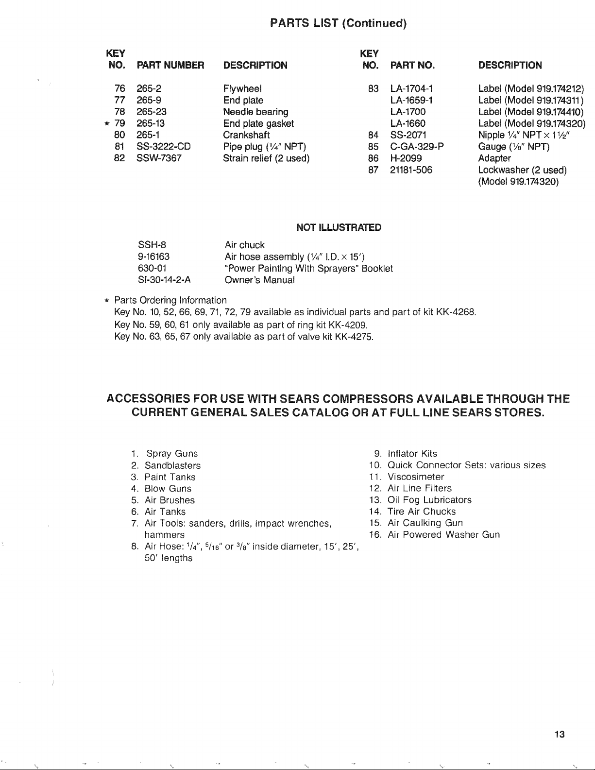
PARTS LiST (Continued)
KEY
NO.
76
77
78
* 79
8O
81
82
PART NUMBER
285-2
265-9
265-23
265-13
265-1
SS-3222-CD
SSW-7367
DESCRiPTiON
Flywheel
End plate
Needle bearing
End plate gasket
Crankshaft
Pipe plug (1/4"NPT)
Strain relief (2 used)
KEY
NO.
83
84
85
88
87
PART NO.
LA-1704-1
LA-1659-1
LA-1700
LA-1660
SS-2071
C-GA-329-P
H-2099
21181-506
NOT iLLUSTRATED
SSH-8
9-16163
630-01
SI-30-14-2-A
Air chuck
Air hose assembly (1/4"I.D.x 15')
"Power Painting With Sprayers" Booklet
Owner's Manual
* Parts Ordering Information
Key No. 10, 52, 66, 89, 71, 72, 79 available as individual parts and part of kit KK-4268.
Key No. 59, 60, 61 only available as part of ring kit KK-4209.
Key No. 83, 65, 67 only available as part of valve kit KK-4275.
DESCRiPTiON
Label (Model 919.174212)
Label (Model 919.174311)
Label (Model 919.174410)
Label (Model 919.174320)
Nipple 1/4"NPT x 11/2"
Gauge (1/8" NPT)
Adapter
Lockwasher (2 used)
(Model 919.174320)
ACCESSORIES FOR USE WiTH SEARS COMPRESSORS AVAILABLE THROUGH THE
CURRENT GENERAL SALES CATALOG OR AT FULL LiNE SEARS STORES.
1. Spray Guns
2. Sandblasters
3. Paint Tanks
4. Blow Guns
5. Air Brushes
6. Air Tanks
7. Air Tools: sanders, drills, impact wrenches,
hammers
8. Air Hose: 1/4",5/16"or 3/8"inside diameter, 15', 25',
50' lengths
9. Inflator Kits
10. Quick Connector Sets: various sizes
11. Viscosimeter
12. Air Line Filters
13. Oil Fog Lubricators
14. Tire Air Chucks
15. Air Caulking Gun
16. Air Powered Washer Gun
% % %
13
Page 14

TROUBLESHOOTING GUIDE
WARNING
PERFORMmNG TROUBLESHOOTING OR REPAIRS MAY EXPOSE VOLTAGE SOURCES, MOVmNG PARTS, OR COM-
PRESSED AiR SOURCES. PERSONAL iNJURY MAY OCCUR iF EXPOSED, PRIOR TO ATTEMPTING ANY
TROUBLESHOOTING OFt REPAIRS, THE COMPRESSOR MUST BE DmSCONNECTED FROM THE POWER SOURCE.
NEVER OPERATE THE OUTFmT WITH THE BELT GUARD REMOVED. THE BELT GUARD SHOULD BE REMOVED
ONLY WHEN THE POWER CORD IS DISCONNECTED.
PROBLEM
Motor Will Not Run
Excessive tank pressure
(safety valve pops off).
CAUSE
Motor overload protection switch
has tripped.
Tank pressure exceeds pressure
switch cut-in pressure.
Fuse blown, circuit breaker tripped.
Wrong extension cord.
Pressure release valve on
pressure switch has not unloaded
head pressure.
Check valve stuck.
Loose electrical connections.
Capacitor on the motor.
Faulty motor.
Pressure switch does not shut off
motor.
Pressure switch cut-out too high.
CORRECTION
Let motor cool off and reset switch by pres-
sing the red reset button located on the end of
motor (see motor section on page 8).
Motor willstart automatically when tank pres-
sure drops below cut-in pressure of pressure
switch.
1) Check fuse box for blown fuse and replace
as necessary. Reset circuit breaker. Do not
use a fuse or circuit breaker with higher rating
than that specified for your particular branch
circuit (see specification chart, page 5).
2) Check for proper fuse, only "Fusetron" Type
T fuses are acceptable.
3) Check for low voltage conditions and/or
proper extension cord as outlined in the motor
section on page 8.
4) Remove check valve and clean or replace if
itis stuck open or closed.
5) Disconnect the other electrical appliances
from circuit or operate the compressor on its
own branch circuit.
Check for proper gauge wire and cord length.
Refer to extension cord recommendations
under Motor Section on page 8.
Bleed line by pushing lever on pressure switch
to OFF position which opens the pressure
release valve. If valve still does not open,
replace it. Models 919.174212and 919.174311
are designed to operate without a head pres-
sure unloader.
A defective check valve results in a constant
air leak at the pressure release valve attached
to the side of the pressure switch (20) when
there is pressure in the air tank and the com-
pressor is not running. Remove and clean or
replace check valve (do not overtighten).
Check in motor connection box and pressure
switch. Pressure switch cover can easily be
removed by lifting cover at rear of switch.
Return to Sears Service Center to check and
replace if necessary.
Unless motor is visibly damaged, remove
motor and have it checked at a local Sears
Service Center.
Move pressure switch lever to the "off" posi-
tion. If outfit doesn't shut-off replace the
switch.
Return outfit to Sears Service Center to check
and adjust or replace if necessary.
14
Page 15

TROUBLESHOOTING GUIDE (Continued)
PROBLEM
Air Leaks
Restricted Air Intake
CAUSE
Tube or hose fittings loose.
Defective check valve.
Leak at welds.
Air leak in safety valve.
Dirty air filter.
CORRECTION
Tighten fittings with audible leak and check
fittings under pressure with soapy water
solution. (Do not overtighten).
A defective check valve results in a constant
air leak at the pressure release valve
attached to the side of the pressure switch
(20) when there is pressure in the air tank
and the compressor is not running. Remove
and clean or replace check valve (do not
overtighten).
DO NOT DRILL mNTO,WELD OR
OTHERWISE MODIFY A_R TANK
OR TANK WILL BE WEAKENED,
TANK MUST BE REPLACED,
Operate safety valve manually by pulling on
ring. If valve still leaks, it should be replaced.
Clean or replace with new.
Squealing Sound
Low Discharge Pressure
Knocking
Excessive Belt Wear
Belts too loose.
No oil in compressor.
Prolonged excessive use of air.
Restricted air intake filter.
Belt too loose.
Hole in hose.
Loose pulley.
Low oil level.
Flywheel loose.
Compressor bolts loose.
Loose belt.
Carbon build up.
Belt too loose.
Tighten wing nut on motor mount.
Add oil to top of fill hole in base.
Decrease amount of air usage, compressor
is not large enough for air requirement. See
specification chart, page 5.
Clean or replace air intake filter.
Tighten wing nut on motor mount.
Check and replace if required.
Tighten pulley set screw.
Check oil level and maintain at prescribed
level.
Make sure flywheel is tight by tightening
screw.
Check all bolts and tighten as required.
Adjust wing nut on motor mount.
Remove head and valve plate. Clean top of
piston and bottom of valve plate. Reassem-
ble using new gasket and torque screws to
25-30 Ft.-Lbs.
Adjust tension using wing nut on motor
mount.
Belt too tight.
Pulley wobble.
Adjust tension using wing nut on motor
mount.
Check for worn keyway or pulley bore result-
ing from running the compressor with loose
pulleys. Also check bent motor shaft.
15
Page 16

Sears l
OWNERS
MANUAL
AIR
SERVICE
MODEL NOS.
919.174212
919.174311
919.174320
919.174410
HOW TO ORDER
REPAIR PARTS
COMPRESSOR
Now that you have purchased your Sears Air Compressor, should a
need ever exist for repair parts or service, simply contact any Sears
Service Center and most Sears, Roebuck and Co. stores. Be sure
to provide all pertinent facts when you call or visit.
The model number of your Sears Air Compressor is 919
This number can be found on the label which is located on the front
of the tank saddle.
WHEN ORDERING REPAIR PARTS, ALWAYS GIVE THE FOL-
LOWING INFORMATION:
• PART NUMBER
• MODEL NUMBER
NOTE:
• PART DESCRIPTION
• NAME OF ITEM
S[-30-14-2-A
If service or repair parts are required for the motor, supply all motor
nameplate information including manufacturers.
All parts listed may be ordered from any Sears Service Center and
most Sears stores.
If the parts you need are not stocked locally, your order will be
electronically transmitted to a Sears Repair Parts Distribution Cen-
ter for handling.
Sears, Roebuck and Co., Chicago, IL 60684 U.S.A.
PRINTED IN U.S.A.
 Loading...