

Page 1

Owner's Manual
JCRHFTSMRN°J
ROTARY LAWN MOWER
6.5 Horsepower
Power-Propelled
21" Multi-Cut
Model No.
917.374801
• EspaSol, p. 21
CAUTION:
Read and follow all
Safety Rules and Instructions
before operating this equipment
Sears, Roebuck and Co., Hoffman Estates, IL 60179 U.S.A.
Visit our Craftsman website: www.sears.com/craftsman
Page 2

Warranty ................................................... 2
Safety Rules .......................................... 2-4
Product Specifications .............................. 4
Assembly / Pre-Operation ..................... 5-6
Operation ............................................ 7-12
Maintenance Schedule ........................... 13
LIMITED TWO YEAR WARRANTY ON CRAFTSMAN POWER MOWER
For two years from date of purchase, when this Craftsman Lawn Mower is maintained,
lubricated, and tuned up according to the operating and maintenance instructions in the
owner's manual, Sears will repair free of charge any defect in material or workmanship.
If this Craftsman Lawn Mower is used for commercial or rental purposes, this warranty
applies for only 90 days from the date of purchase.
This Warranty does not cover:
• Expendable items which become worn during normal use, such as rotary mower
blades, blade adapters, belts, air cleaners and spark plug.
• Repairs necessary because of operator abuse or negligence, including bent crank-
shafts and the failure to maintain the equipment according to the instructions con-
tained in the owner's manual.
Maintenance ...................................... 13-16
Service and Adjustments ................... 16-18
Storage .............................................. 18-19
Troubleshooting ................................. 19-20
Repair Parts ....................................... 40-47
Sears Service .......................... Back Cover
Warranty service is available by returning the Craftsman power mower to the nearest Sears
Parts & Repair Center in the United States. This warranty applies only while this product
is used in the United States.
This Warranty gives you specific legal rights, and you may also have other rights which
vary from state to state.
Sears, Roebuck And Co., D/817 WA, Hoffman Estates, IL 60179
IMPORTANT: This cutting machine is capable of amputating hands and feet and throw-
ing objects. Failure to observe the following safety instructions could result in serious
injury or death.
_¢LLookfor this symbol to point out
important safety precautions. It means
CAUTION!H BECOME ALERT!H
YOUR SAFETY IS INVOLVED.
_,WARNING: In order to prevent ac-
cidental starting when setting up, trans-
porting, adjusting or making repairs,
always disconnect spark plug wire and
place wire where it cannot come in con-
tact with plug.
_JLWARNING: Engine exhaust, some of its
constituents, and certain vehicle compo-
nents contain or emit chemicals known
to the State of California to cause cancer
and birth defects or other reproductive
harm.
Ai:i,WARNING: Battery posts, terminals and
related accessories contain lead and lead
compounds, chemicals known to the State
of California to cause cancer and birth
defects or other reproductive harm. Wash
hands after handling.
_, CAUTION: Muffler and other engine
parts become extremely hot during
operation and remain hot after engine has
stopped. To avoid severe burns on contact,
stay away from these areas.
2
Page 3
I. GENERAL OPERATION
• Read, understand, and follow all
instructions on the machine and in the
manual(s) before starting. Be thoroughly
familiar with the controls and the proper
use of the machine before starting.
• Do not put hands or feet near or under
rotating parts. Keep clear of the dis-
charge opening at all times.
• Only allow responsible individuals, who
are familiar with the instructions, to oper-
ate the machine.
• Clear the area of objects such as rocks,
toys, wire, bones, sticks, etc., which
could be picked up and thrown by the
blade.
• Be sure the area is clear of other people
before mowing. Stop machine if anyone
enters the area.
• Do not operate the mower when bare-
foot or wearing open sandals. Always
wear substantial foot wear.
• Do not pull mower backwards unless
absolutely necessary. Always look down
and behind before and while moving
backwards.
• Do not operate the mower without
proper guards, plates, grass catcher or
other safety protective devices in place.
• See manufacturer's instructions for
proper operation and installation of
accessories. Only use accessories ap-
proved by the manufacturer.
• Stop the blade(s) when crossing gravel
drives, walks, or roads.
• Stop the engine (motor) whenever you
leave the equipment, before cleaning the
mower or unclogging the chute.
• Shut the engine (motor) off and wait until
the blade comes to complete stop before
removing grass catcher.
• Mow only in daylight or good artificial
light.
• Do not operate the machine while under
the influence of alcohol or drugs.
• Never operate machine in wet grass.
Always be sure of your footing: keep a
firm hold on the handle and walk; never
run.
• Disengage the self-propelled mech-
anism or drive clutch on mowers so
equipped before starting the engine
(motor).
• If the equipment should start to vibrate
abnormally, stop the engine (motor) and
check immediately for the cause. Vibra-
tion is generally a warning of trouble.
• Always wear safety goggles or safety
glasses with side shields when operating
mower.
II. SLOPE OPERATION
Slopes are a major factor related to slip
and fall accidents which can result in
severe injury.All slopes require extra cau-
tion. If you feel uneasy on a slope, do not
mow it.
DO:
• Mow across the face of slopes: never
up and down. Exercise extreme caution
when changing direction on slopes.
• Remove obstacles such as rocks, tree
limbs, etc.
• Watch for holes, ruts, or bumps. Tall
grass can hide obstacles.
DO NOT:
• Do not trim near drop-offs, ditches or
embankments. The operator could lose
footing or balance.
• Do not trim excessively steep slopes.
• Do not mow on wet grass. Reduced foot-
ing could cause slipping.
III. CHILDREN
Tragic accidents can occur if the operator
is not alert to the presence of children.
Children are often attracted to the machine
and the mowing activity. Never assume
that children will remain where you last
saw them.
• Keep children out of the trimming area
and under the watchful care of another
responsible adult.
• Be alert and turn machine off if children
enter the area.
• Before and while walking backwards,
look behind and down for small children.
• Never allow children to operate the ma-
chine.
• Use extra care when approaching blind
corners, shrubs, trees, or other objects
that may obscure vision.
IV. SERVICE
• Use extra care in handling gasoline and
other fuels. They are flammable and
vapors are explosive.
- Use only an approved container.
- Never remove gas cap or add fuel
with the engine running.
Allow engine to cool before refueling.
Do not smoke.
- Never refuel the machine indoors.
- Never store the machine or fuel
container inside where there is an
open flame, such as a water heater.
• Never run a machine inside a closed area.
• Never make adjustments or repairs with
the engine (motor) running. Disconnect the
spark plug wire, and keep the wire away
3 from the plug to prevent accidental starting.
Page 4

• Keepnutsand bolts,especiallyblade
attachmentbolts,tightand keepequip-
mentin good condition.
• Nevertamperwithsafetydevices.Check
their properoperationregularly.
• Keep machinefree of grass, leaves,or
otherdebrisbuild-up.Cleanoilorfuel spill-
age.Allowmachinetocoolbeforestoring.
• Stopandinspectthe equipmentifyou
strikeanobject.Repair,if necessary,
beforerestarting.
• Neverattempttomakewheelheightadjust-
• Grasscatchercomponentsaresubject
towear,damage,anddeterioration,
whichcouldexposemovingparts or
allowobjectsto bethrown.Frequently
checkcomponentsandreplacewith
manufacturer'srecommendedparts,
whennecessary.
• Mowerbladesaresharpandcancut.
Wraptheblade(s)or weargloves,and
useextracautionwhen servicingthem.
• Donot changetheenginegovernorset-
tingor overspeedtheengine.
mentswhiletheengine(motor)isrunning.
SerialNumber:
Dateof Purchase:
GasolineCapacity/Type: 1.0 Quarts (Unleaded Regular)
Oil Capacity: 18.5 Ounces
Oil Type (API SG-SL): SAE 30 (above 32°F) or SAE 10W-30
Spark Plug (Gap: .030") NGK BPR6ES
Valve Clearance (± 0.04 mm): Intake: 0.015 mm; Exhaust: 0.020 mm
Blade Bolt Torque: 35-40 ft. Ibs.
The model and serial numbers will be found on a decal on the rear of the lawn mower
housing. Record both serial number and date of purchase in space provided above.
Repair Protection Agreements
Congratulations on making a smart pur-
chase. Your new Craftsman® product is
designed and manufactured for years of
dependable operation. But like all prod-
ucts, it may require repair from time to
time. That's when having a Repair Protec-
tion Agreement can save you money and
aggravation.
Purchase a Repair Protection Agreement
now and protect yourself from unexpected
hassle and expense.
Here's what's included in the Agreement:
• Expert service by our 12,000 profe-
sional repair specialists.
• Unlimited service and no charge for
parts and labor on all covered repairs.
• Product replacement if your covered
product can't be fixed.
• Discount of 10% from regular price of
service and service-related parts not
covered by the agreement; also, 10%
off regular price of preventive mainte-
nance check.
Fast help by phone - phone support
from a Sears technician on products
requiring in-home repair, plus conve-
nient repair scheduling.
Once you purchase the Agreement, a
simple phone call is all that it takes for you
to schedule service. You can call anytime
day or night, or schedule a service ap-
pointment online.
Sears has over 12,000 professional repair
specialists, who have access to over 4.5
million quality parts and accessories.
That's the kind of professionalism you can
count on to help prolong the life of your
new purchase for years to come. Purchase
your Repair Protection Agreement today!
Some limitations and exclusions apply.
For prices and additional information
call 1-800-827-6655.
Sears Installation Service
For Sears professional installation of home
appliances, garage door openers, water
heaters, and other major home items, in
the U.S.A. call 1-800-4-MY-HOME®.
4
Page 5
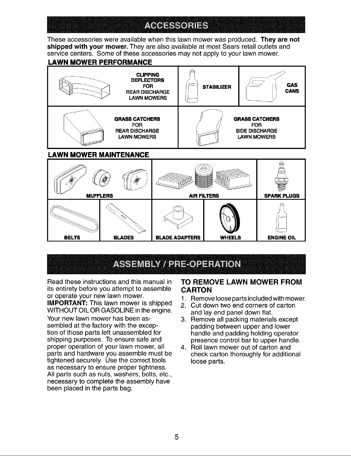
These accessories were available when this lawn mower was produced. They are not
shipped with your mower. They are also available at most Sears retail outlets and
service centers. Some of these accessories may not apply to your lawn mower.
LAWN MOWER PERFORMANCE
CLIPPING
FOR -- STABILIZER
___ DEFLECTORS --
REAR DISCHARGE
LAWN MOWERS L
_\\ \\ FOR FOR
\\ GRASS CATCHERS GRASS CATCHERS
LAWN MOWERS LAWN MOWERS
REAR DISCHARGE SIDE DISCHARGE
LAWN MOWER MAINTENANCE
MUFFLERS
BELTS BLADES
BLADE ADAFq'ERS WHEELS
Read these instructions and this manual in
its entirety before you attempt to assemble
or operate your new lawn mower.
IMPORTANT: This lawn mower is shipped
WITHOUT OIL OR GASOLINE in the engine.
Your new lawn mower has been as-
sembled at the factory with the excep-
tion of those parts left unassembled for
shipping purposes. To ensure safe and
proper operation of your lawn mower, all
parts and hardware you assemble must be
tightened securely. Use the correct tools
as necessary to ensure proper tightness.
All parts such as nuts, washers, bolts, etc.,
necessary to complete the assembly have
been placed in the parts bag.
AIR FILTERS
SPARK PLUGS
ENGINE OIL
TO REMOVE LAWN MOWER FROM
CARTON
1. Remove loose parts included with mower.
2. Cut down two end corners of carton
and lay end panel down flat.
3. Remove all packing materials except
padding between upper and lower
handle and padding holding operator
presence control bar to upper handle.
4. Roll lawn mower out of carton and
check carton thoroughly for additional
loose parts.
5
Page 6
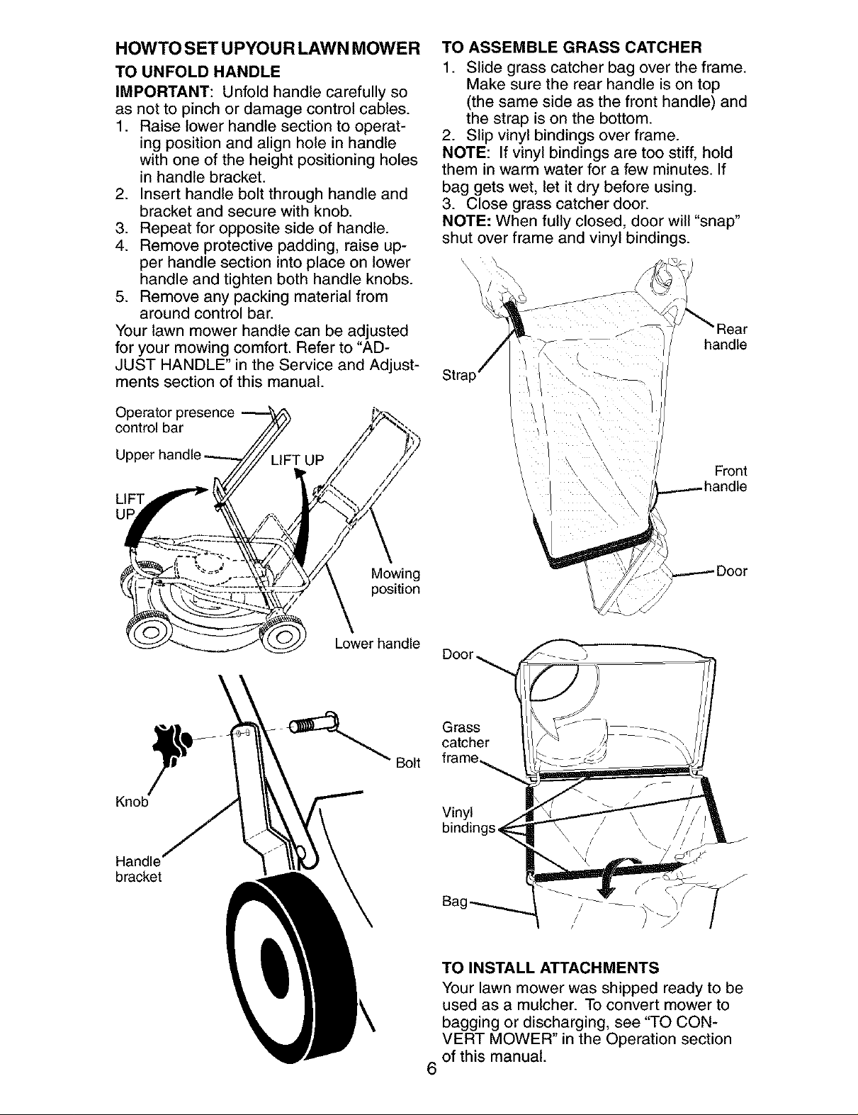
HOWTO SET UPYOUR LAWN MOWER
TO UNFOLD HANDLE
IMPORTANT: Unfold handle carefully so
as not to pinch or damage control cables.
1. Raise lower handle section to operat-
ing position and align hole in handle
with one of the height positioning holes
in handle bracket.
2. Insert handle bolt through handle and
bracket and secure with knob.
3. Repeat for opposite side of handle.
4. Remove protective padding, raise up-
per handle section into place on lower
handle and tighten both handle knobs.
5. Remove any packing material from
around control bar.
Your lawn mower handle can be adjusted
for your mowing comfort. Refer to "AD-
JUST HANDLE" in the Service and Adjust-
ments section of this manual.
Operator presence
control bar
TO ASSEMBLE GRASS CATCHER
1. Slide grass catcher bag over the frame.
Make sure the rear handle is on top
(the same side as the front handle) and
the strap is on the bottom.
2. Slip vinyl bindings over frame.
NOTE: If vinyl bindings are too stiff, hold
them in warm water for a few minutes. If
bag gets wet, let it dry before using.
3. Close grass catcher door.
NOTE: When fully closed, door will "snap"
shut over frame and vinyl bindings.
\
J
--- handle
LIFT
UF
Knob
Handle'
bmc_t
Mowing
position
Lower handle
_ Bolt
Front
Door,
Grass
catcher
Vinyl
TO INSTALL ATTACHMENTS
Your lawn mower was shipped ready to be
used as a mulcher. To convert mower to
bagging or discharging, see "TO CON-
VERT MOWER" in the Operation section
of this manual.
6
Page 7
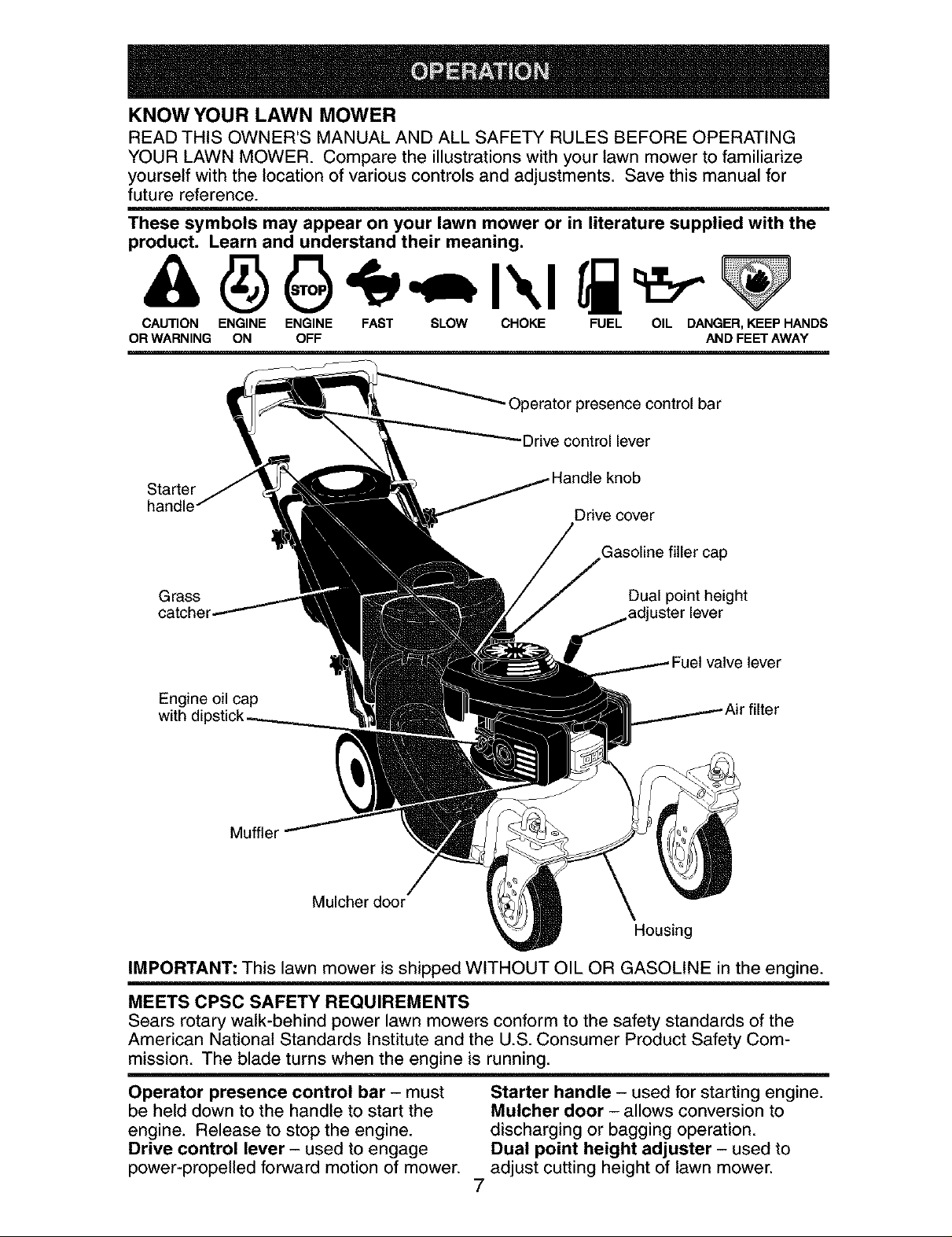
KNOW YOUR LAWN MOWER
READ THIS OWNER'S MANUAL AND ALL SAFETY RULES BEFORE OPERATING
YOUR LAWN MOWER. Compare the illustrations with your lawn mower to familiarize
yourself with the location of various controls and adjustments. Save this manual for
future reference.
These symbols may appear on your lawn mower or in literature supplied with the
product. Learn and understand their meaning.
CAUTION ENGINE ENGINE FAST SLOW CHOKE FUEL OIL DANGER, KEEP HANDS
OR WARNING ON OFF AND FEET AWAY
Operator presence control bar
Drive control lever
Starter
handle
Drive cover
Gasoline filler cap
Grass Dual point height
,adjuster lever
lever
Engine oil cap
with er
Muffler
Mulcher door
Housing
IMPORTANT: This lawn mower is shipped WITHOUT OIL OR GASOLINE in the engine.
MEETS CPSC SAFETY REQUIREMENTS
Sears rotary walk-behind power lawn mowers conform to the safety standards of the
American National Standards Institute and the U.S. Consumer Product Safety Com-
mission. The blade turns when the engine is running.
Operator presence control bar - must
be held down to the handle to start the
engine. Release to stop the engine.
Drive control lever - used to engage
power-propelled forward motion of mower.
Starter handle - used for starting engine.
Mulcher door - allows conversion to
discharging or bagging operation.
Dual point height adjuster - used to
adjust cutting height of lawn mower.
7
Page 8
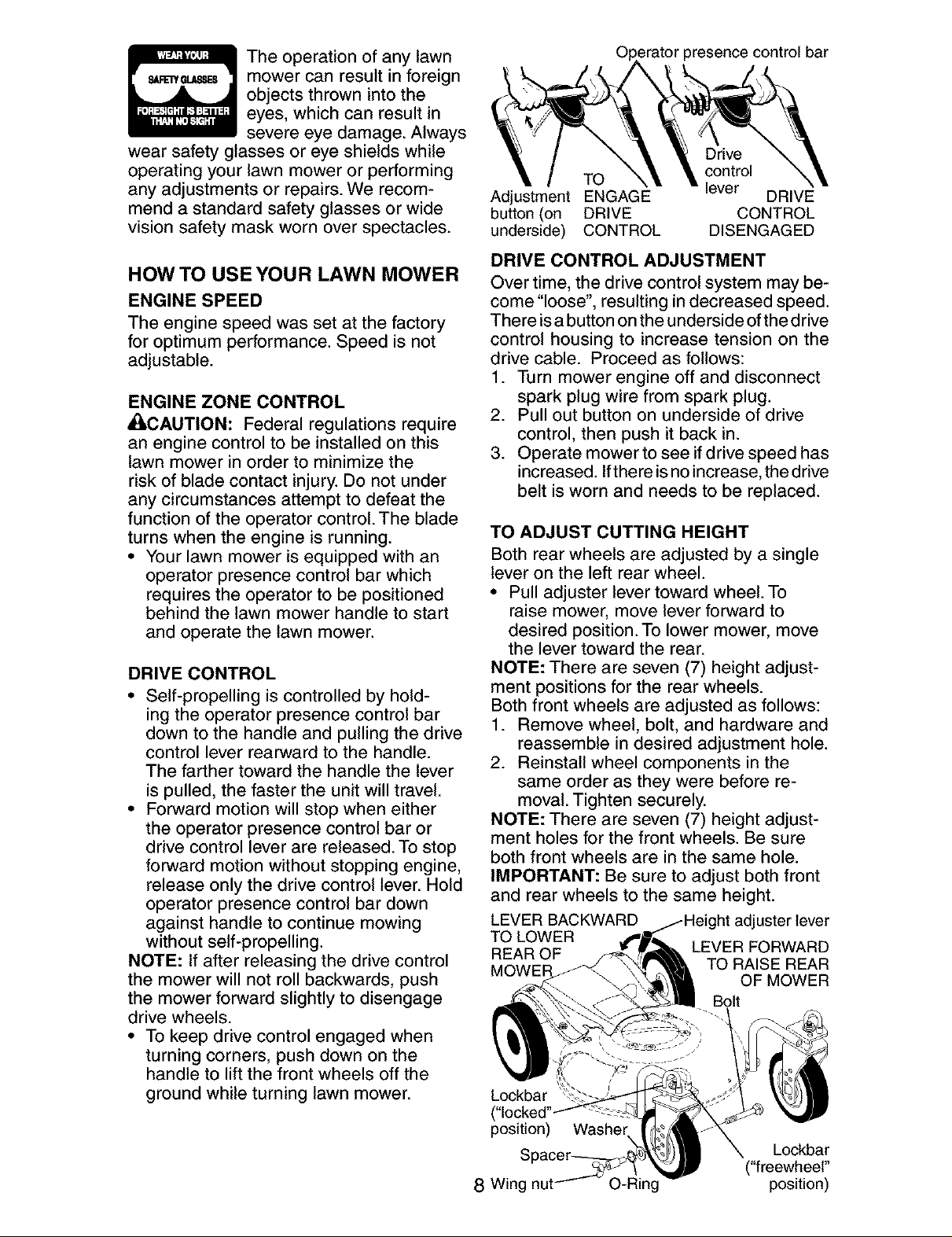
Theoperationof anylawn
mowercanresultin foreign
objectsthrownintothe
eyes,whichcan resultin
severeeyedamage.Always
wearsafetyglassesor eyeshieldswhile
operatingyour lawnmoweror performing
anyadjustmentsor repairs.Werecom-
mendastandardsafetyglassesor wide
visionsafetymaskwornoverspectacles.
HOW TO USE YOUR LAWN MOWER
ENGINE SPEED
The engine speed was set at the factory
for optimum performance. Speed is not
adjustable.
ENGINE ZONE CONTROL
_CAUTION: Federal regulations require
an engine control to be installed on this
lawn mower in order to minimize the
risk of blade contact injury. Do not under
any circumstances attempt to defeat the
function of the operator control. The blade
turns when the engine is running.
• Your lawn mower is equipped with an
operator presence control bar which
requires the operator to be positioned
behind the lawn mower handle to start
and operate the lawn mower.
DRIVE CONTROL
• Self-propelling is controlled by hold-
ing the operator presence control bar
down to the handle and pulling the drive
control lever rearward to the handle.
The farther toward the handle the lever
is pulled, the faster the unit will travel.
• Forward motion will stop when either
the operator presence control bar or
drive control lever are released. To stop
forward motion without stopping engine,
release only the drive control lever. Hold
operator presence control bar down
against handle to continue mowing
without self-propelling.
NOTE: If after releasing the drive control
the mower will not roll backwards, push
the mower forward slightly to disengage
drive wheels.
• To keep drive control engaged when
turning corners, push down on the
handle to lift the front wheels off the
ground while turning lawn mower.
_=ratorpresence control bar
Drive
control
Adjustment ENGAGE DRIVE
button (on DRIVE CONTROL
underside) CONTROL DISENGAGED
TO lever
DRIVE CONTROL ADJUSTMENT
Over time, the drive control system may be-
come "loose", resulting in decreased speed.
There isa button on the underside of the drive
control housing to increase tension on the
drive cable. Proceed as follows:
1. Turn mower engine off and disconnect
spark plug wire from spark plug.
2. Pull out button on underside of drive
control, then push it back in.
3. Operate mower to see ifdrive speed has
increased. Ifthere isno increase, the drive
belt is worn and needs to be replaced.
TO ADJUST CUTTING HEIGHT
Both rear wheels are adjusted by a single
lever on the left rear wheel.
• Pull adjuster lever toward wheel. To
raise mower, move lever forward to
desired position. To lower mower, move
the lever toward the rear.
NOTE: There are seven (7) height adjust-
ment positions for the rear wheels.
Both front wheels are adjusted as follows:
1. Remove wheel, bolt, and hardware and
reassemble in desired adjustment hole.
2. Reinstall wheel components in the
same order as they were before re-
moval. Tighten securely.
NOTE: There are seven (7) height adjust-
ment holes for the front wheels. Be sure
both front wheels are in the same hole.
IMPORTANT: Be sure to adjust both front
and rear wheels to the same height.
LEVER BACKWARD
TOLOWER
REAR OF
MOWEF
Lockbar
("locked'
position)
8 Wing nu ing
Washer
adjuster lever
LEVER FORWARD
TO RAISE REAR
OF MOWER
Bolt
Lockbar
("freewheel"
position)
Page 9
CASTER WHEEL OPERATION
The front wheels can be "locked" into
position or set to '"_reewheel" for better
maneuverability. Placing the Iockbars in
the outer holes of the adjustment brackets
"locks" the front wheels. Likewise, placing
the Iockbars in the inner holes of the ad-
justment brackets allows the front wheels
to spin freely ("freewheel").
• Lift Iockbar until the frontmost end
clears the adjustment bracket, then pivot
Iockbar to desired position.
IMPORTANT: Front wheels must be
"locked" into position when operating on
a slope. Mow across the face of slopes:
never up and down.
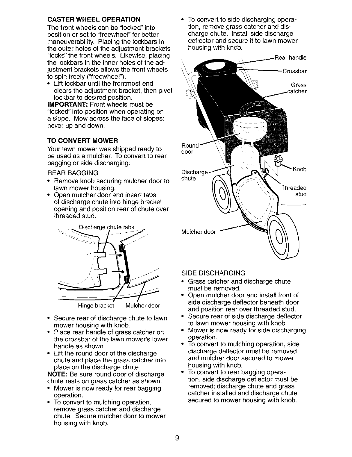
TO CONVERT MOWER
Your lawn mower was shipped ready to
be used as a mulcher. To convert to rear
bagging or side discharging:
REAR BAGGING
• Remove knob securing mulcher door to
lawn mower housing.
• Open mulcher door and insert tabs
of discharge chute into hinge bracket
opening and position rear of chute over
threaded stud.
• To convert to side discharging opera-
tion, remove grass catcher and dis-
charge chute. Install side discharge
deflector and secure it to lawn mower
housing with knob.
Grass
door
Knob
chute
Threaded
stud
Discharge chute tabs
_J
J
I
Hinge bracket Mulcher door
• Secure rear of discharge chute to lawn
mower housing with knob.
• Place rear handle of grass catcher on
the crossbar of the lawn mower's lower
handle as shown.
• Lift the round door of the discharge
chute and place the grass catcher into
place on the discharge chute.
NOTE: Be sure round door of discharge
chute rests on grass catcher as shown.
• Mower is now ready for rear bagging
operation.
• To convert to mulching operation,
remove grass catcher and discharge
chute. Secure mulcher door to mower
housing with knob.
Mulcher door
SIDE DISCHARGING
• Grass catcher and discharge chute
must be removed.
• Open mulcher door and install front of
side discharge deflector beneath door
and position rear over threaded stud.
• Secure rear of side discharge deflector
to lawn mower housing with knob.
• Mower is now ready for side discharging
operation.
• To convert to mulching operation, side
discharge deflector must be removed
and mulcher door secured to mower
housing with knob.
• To convert to rear bagging opera-
tion, side discharge deflector must be
removed; discharge chute and grass
catcher installed and discharge chute
secured to mower housing with knob.
9
Page 10
Mulcher door Knob
X eaded
stud
Side
discharge
deflector
SIMPLE STEPS TO REMEMBER WHEN
CONVERTING YOUR LAWN MOWER
FOR MULCHING -
1. Grass catcher, discharge chute and
side discharge deflector removed.
2. Mulcher door secured to mower hous-
ing with knob.
FOR REAR BAGGING -
1. Side discharge deflector removed.
2. Grass catcher and discharge chute
installed with discharge chute secured
to lawn mower housing with knob.
3. Round door of discharge chute resting
on top of grass catcher.
FOR SIDE DISCHARGING -
1. Grass catcher and discharge chute
removed.
2. Side discharge deflector installed and
secured to mower housing with knob.
_CAUTION: Do not run your lawn mower
without mulcher door closed; side dis-
charge deflector installed, or discharge
chute and approved grass catcher in
place. Never attempt to operate the lawn
mower with mulcher door or round door
removed or propped open.
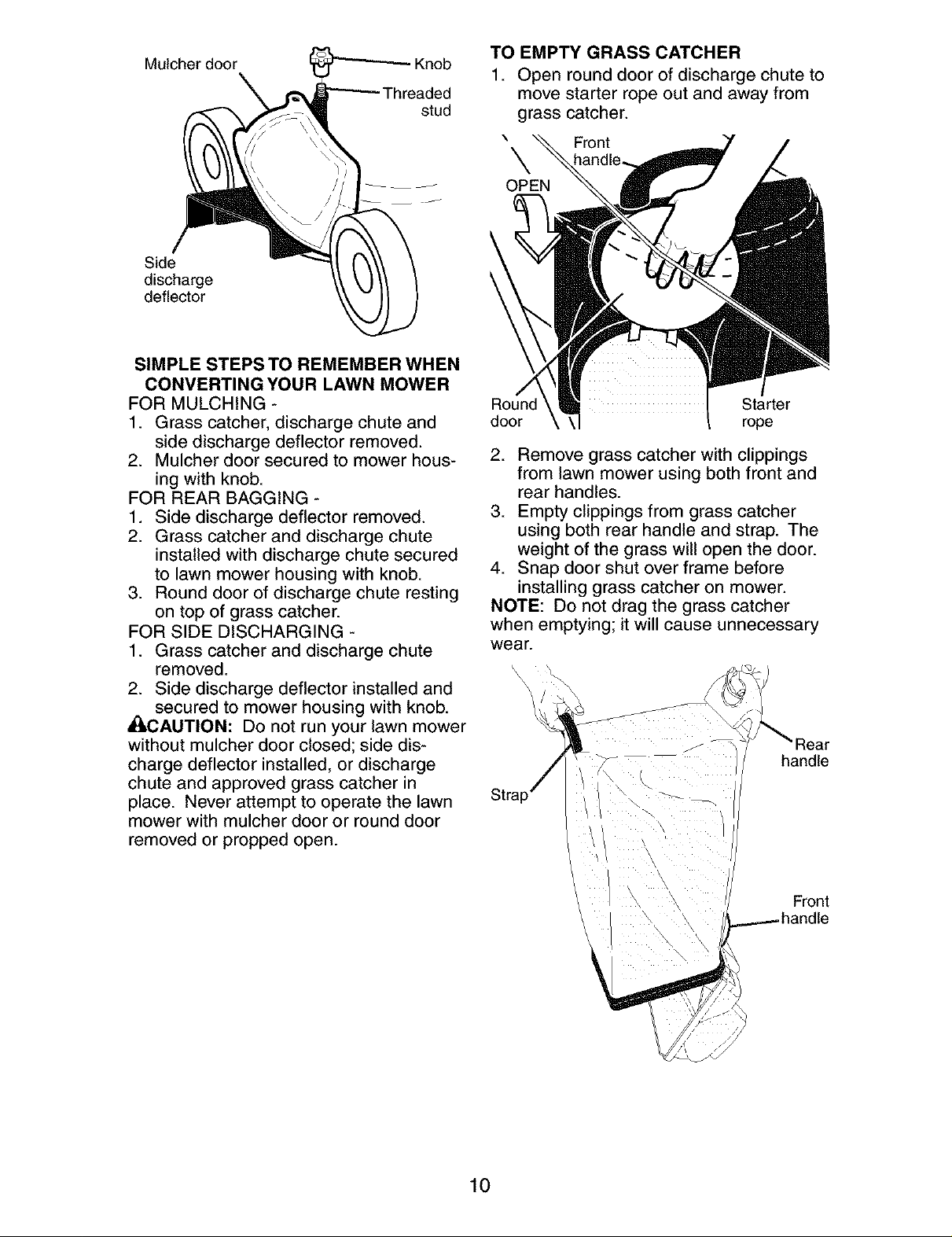
TO EMPTY GRASS CATCHER
1. Open round door of discharge chute to
move starter rope out and away from
grass catcher.
\ Front
\
OPEN
Round Starter
door rope
2. Remove grass catcher with clippings
from lawn mower using both front and
rear handles.
3. Empty clippings from grass catcher
using both rear handle and strap. The
weight of the grass will open the door.
4. Snap door shut over frame before
installing grass catcher on mower.
NOTE: Do not drag the grass catcher
when emptying; it will cause unnecessary
wear.
__J
jf
j P_
handle
10
Front
Page 11
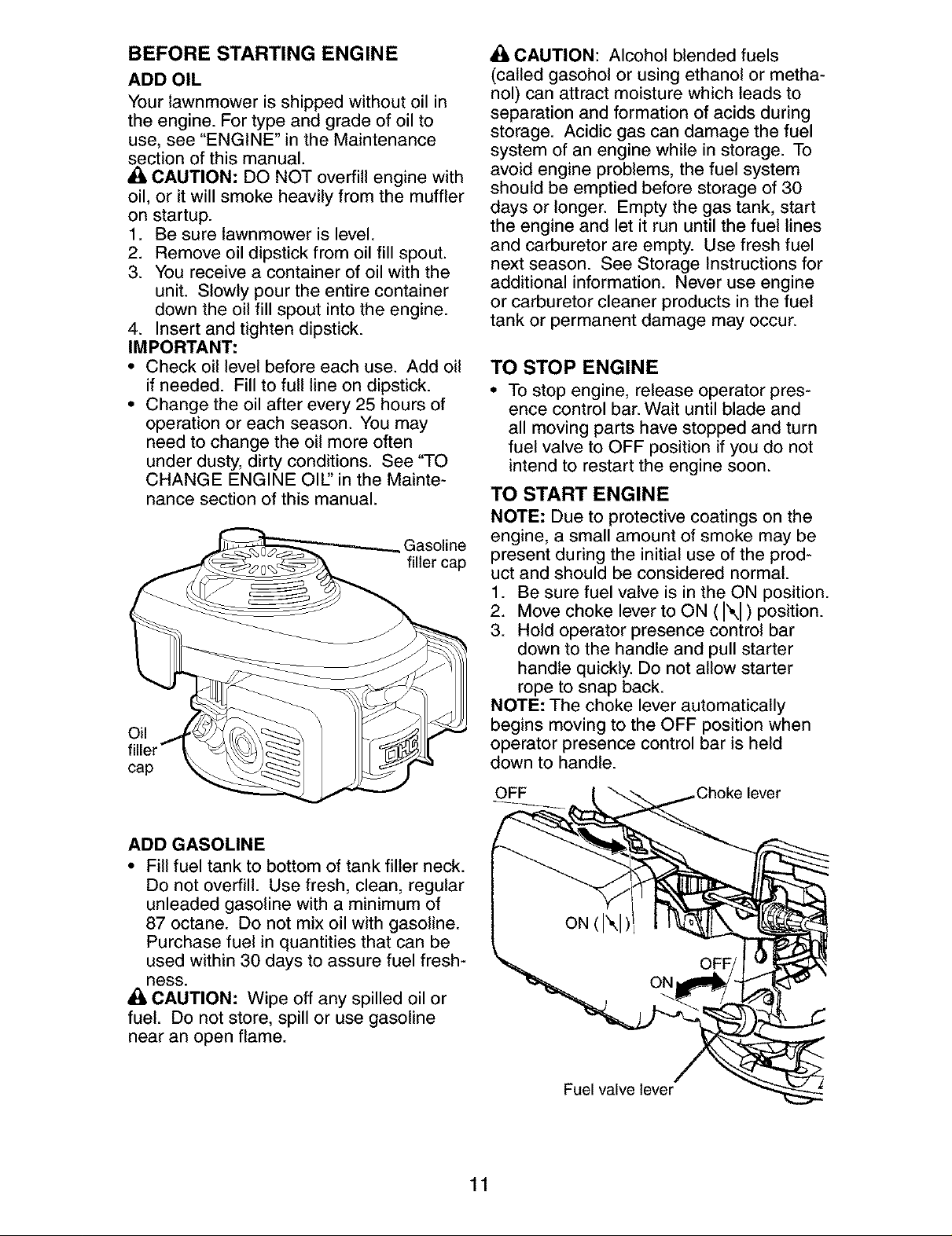
BEFORE STARTING ENGINE
ADD OIL
Your lawnmower is shipped without oil in
the engine. For type and grade of oil to
use, see "ENGINE" in the Maintenance
section of this manual.
CAUTION: DO NOT overfill engine with
oil, or it will smoke heavily from the muffler
on startup.
1. Be sure lawnmower is level.
2. Remove oil dipstick from oil fill spout.
3. You receive a container of oil with the
unit. Slowly pour the entire container
down the oil fill spout into the engine.
4. Insert and tighten dipstick.
IMPORTANT:
• Check oil level before each use. Add oil
if needed. Fill to full line on dipstick.
• Change the oil after every 25 hours of
operation or each season. You may
need to change the oil more often
under dusty, dirty conditions. See "TO
CHANGE ENGINE OIL' in the Mainte-
nance section of this manual.
Gasoline
filler cap
Oil
cap
A CAUTION: Alcohol blended fuels
(called gasohol or using ethanol or metha-
nol) can attract moisture which leads to
separation and formation of acids during
storage. Acidic gas can damage the fuel
system of an engine while in storage. To
avoid engine problems, the fuel system
should be emptied before storage of 30
days or longer. Empty the gas tank, start
the engine and let it run until the fuel lines
and carburetor are empty. Use fresh fuel
next season. See Storage Instructions for
additional information. Never use engine
or carburetor cleaner products in the fuel
tank or permanent damage may occur.
TO STOP ENGINE
• To stop engine, release operator pres-
ence control bar. Wait until blade and
all moving parts have stopped and turn
fuel valve to OFF position if you do not
intend to restart the engine soon.
TO START ENGINE
NOTE: Due to protective coatings on the
engine, a small amount of smoke may be
present during the initial use of the prod-
uct and should be considered normal.
1. Be sure fuel valve is in the ON position.
2. Move choke lever to ON ( I\I ) position.
3. Hold operator presence control bar
down to the handle and pull starter
handle quickly. Do not allow starter
rope to snap back.
NOTE: The choke lever automatically
begins moving to the OFF position when
operator presence control bar is held
down to handle.
OFF lever
ADD GASOLINE
• Fill fuel tank to bottom of tank filler neck.
Do not overfill. Use fresh, clean, regular
unleaded gasoline with a minimum of
87 octane. Do not mix oil with gasoline.
Purchase fuel in quantities that can be
used within 30 days to assure fuel fresh-
ness.
CAUTION: Wipe off any spilled oil or
fuel. Do not store, spill or use gasoline
near an open flame.
Fuel valve lever
11
Page 12
MOWING TIPS
• Under certain conditions, such as very
tall grass, it may be necessary to raise
the height of cut to reduce pushing
effort and to keep from overloading the
engine and leaving clumps of grass clip-
pings. It may also be necessary to re-
duce ground speed and/or run the lawn
mower over the area a second time.
• For extremely heavy cutting, reduce the
width of cut by overlapping previously
cut path and mow slowly.
• For better grass bagging and most cut-
ting conditions, the engine speed should
be set in the FAST position.
• Pores in cloth grass catchers can be-
come filled with dirt and dust with use
and catchers will collect less grass. To
prevent this, regularly hose catcher off
with water and let dry before using.
• Keep top of engine around starter clear
and clean of grass clippings and chaff.
This will help engine air flow and extend
engine life.
MULCHING MOWING TIPS
IMPORTANT: For best performance,
keep mower housing free of built-up
grass and trash. See "CLEANING" in the
Maintenance section of this manual.
• The special mulching blade will recut
the grass clippings many times and
reduce them in size so that as they fall
onto the lawn they will disperse into
the grass and not be noticed. Also, the
mulched grass will biodegrade quickly
to provide nutrients for the lawn. Always
mulch with your highest engine (blade)
speed as this will provide the best recut-
ting action of the blades.
• Avoid cutting your lawn when it is wet.
Wet grass tends to form clumps and
interferes with the mulching action. The
best time to mow your lawn is the early
afternoon. At this time the grass has
dried, yet the newly cut area will not be
exposed to direct sunlight.
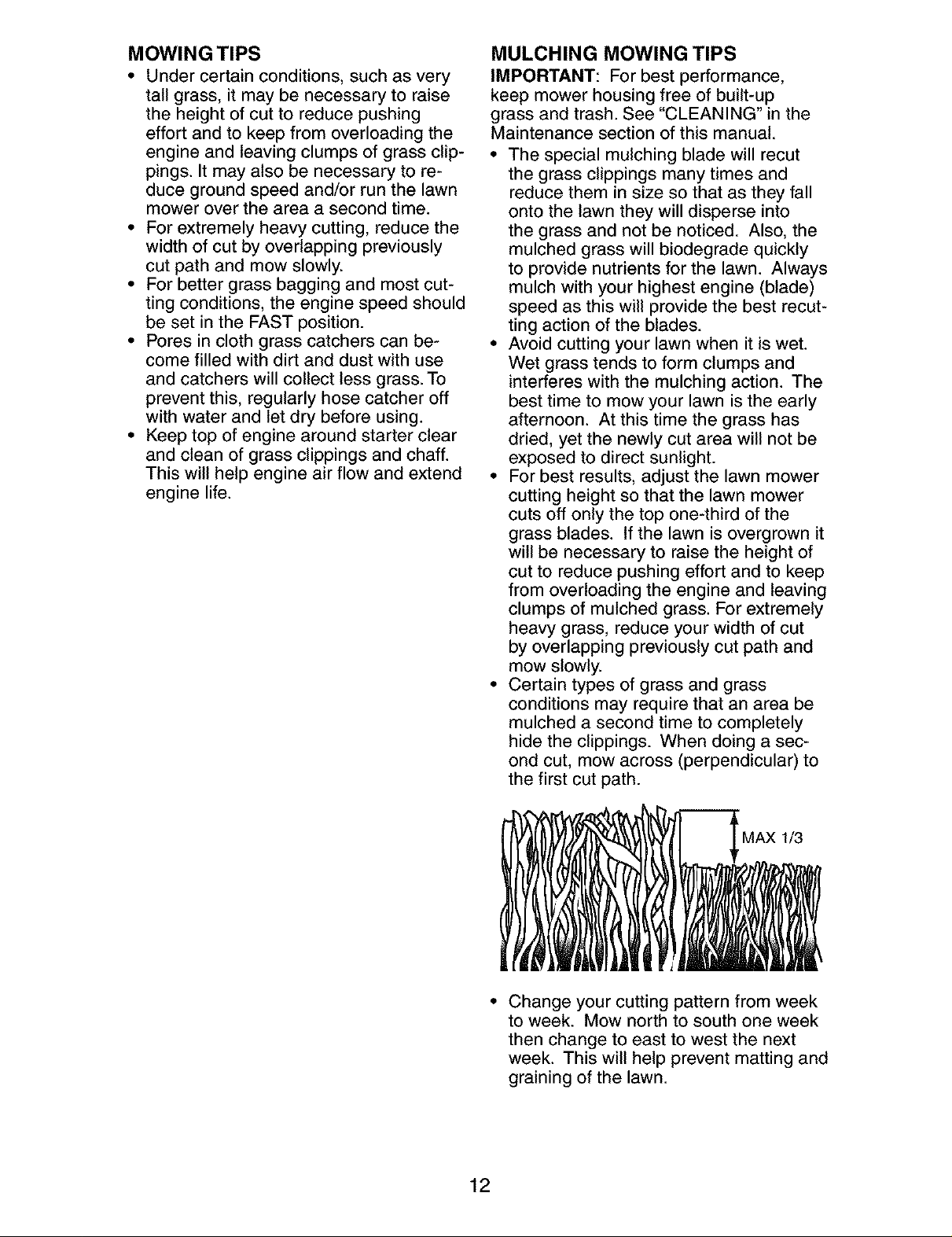
• For best results, adjust the lawn mower
cutting height so that the lawn mower
cuts off only the top one-third of the
grass blades. If the lawn is overgrown it
will be necessary to raise the height of
cut to reduce pushing effort and to keep
from overloading the engine and leaving
clumps of mulched grass. For extremely
heavy grass, reduce your width of cut
by overlapping previously cut path and
mow slowly.
• Certain types of grass and grass
conditions may require that an area be
mulched a second time to completely
hide the clippings. When doing a sec-
ond cut, mow across (perpendicular) to
the first cut path.
• Change your cutting pattern from week
to week. Mow north to south one week
then change to east to west the next
week. This will help prevent matting and
graining of the lawn.
12
Page 13
MAINTENANCE BEFOREAPTEREVERY EVERY EVERYBEFORE
EACH EACH 10 25HOURS 100
SCHEDULE USE USE HOURS ORSEASON HOURS STORAGE
Check for Loose Fasteners
L Clean / Inspect Grass Catcher *
Check Tires
_ Check Drive Wheels
Clean Lawn Mower ....
M Clean under Drive Cover ***
D Check Drive Belt / Pulleys ***
_ Check / Sharpen / Replace Blade
R Lubrication
Clean and Recharge Battery **
Check Engine Oil level
E Change Engine Oil
_ Clean Air Filter
Inspect Muffler
_1 Replace Spark Plug
E Replace Air Filter Paper Cartridge
Empty fuel system or add Stabilizer
* (if so equipped)
** Electric-Start mowers
*** Power-Propelled mowers
**** Use a scraper
to clean under deck
1 - Change more often if operating under a heavy load or in high outdoor temperatures.
2 - Service more often if operating in dirty or dusty conditions.
3 - Replace blades more often when mowing in sandy soil.
4 - Charge 48 hours at end of season.
5 - And after each 5 hours of use.
i/ i/
i/
t/
t_,2
GENERAL RECOMMENDATIONS
The warranty on this lawn mower does not
cover items that have been subjected to
operator abuse or negligence. To receive
full value from the warranty, operator must
maintain unit as instructed in this manual.
Some adjustments will need to be made
periodically to properly maintain your unit.
At least once a season, check to see if
you should make any of the adjustments
described in the Service and Adjustments
section of this manual.
• At least once a year, replace the spark
plug, clean or replace air filter element
and check blade for wear. A new spark
plug and clean/new air filter element
assure proper air-fuel mixture and help
your engine run better and last longer.
• Follow the maintenance schedule in this
manual.
BEFORE EACH USE
• Check engine oil level.
• Check for loose fasteners.
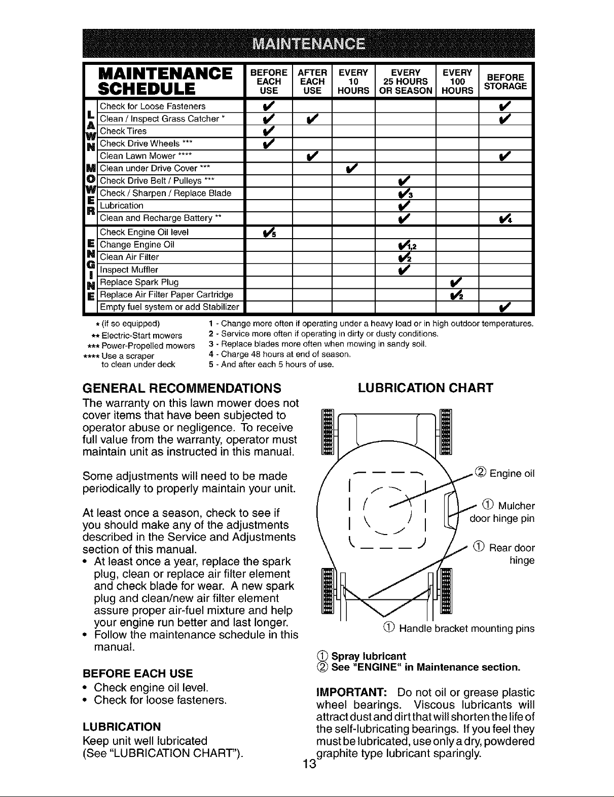
LUBRICATION
Keep unit well lubricated
(See "LUBRICATION CHART").
LUBRICATION CHART
(_) Mulcher
door hinge pin
Rear door
Handle bracket mounting pins
_ Spray lubricant
See "ENGINE" in Maintenance section.
IMPORTANT: Do not oil or grease plastic
wheel bearings. Viscous lubricants will
attract dust and dirt that will shorten the life of
the self-lubricating bearings. If you feel they
must be lubricated, use only a dry, powdered
3graphite type lubricant sparingly.
1
ine oil
hinge
Page 14
LAWN MOWER
Always observe safety rules when per-
forming any maintenance.
TIRES
• Keep tires free of gasoline, oil, or insect
control chemicals which can harm rubber.
• Avoid stumps, stones, deep ruts, sharp
objects and other hazards that may
cause tire damage.
DRIVE WHEELS
Check rear drive wheels each time you mow
to be sure they move freely. The wheels not
turning freely means trash, grass cuttings,
etc., may be inside the drive wheel and dust
cover area and must be cleaned out to free
drive wheels. If necessary to clean the drive
wheels, check both rear wheels.
BLADE CARE
For best results, mower blade must be kept
sharp. Replace a bent or damaged blade.
TO REMOVE BLADE
1. Disconnect spark plug wire from spark
plug and place wire where it cannot
come in contact with plug.
2. Turn lawn mower on its side. Make
sure air filter and carburetor are up.
3. Use a wood block between blade and
mower housing to prevent blade from
turning when removing blade bolt.
NOTE: Protect your hands with gloves
and/or wrap blade with heavy cloth.
4. Remove blade bolt by turning counter-
clockwise.
5. Remove blade and attaching hard-
ware (bolt, lock washer and hardened
washer).
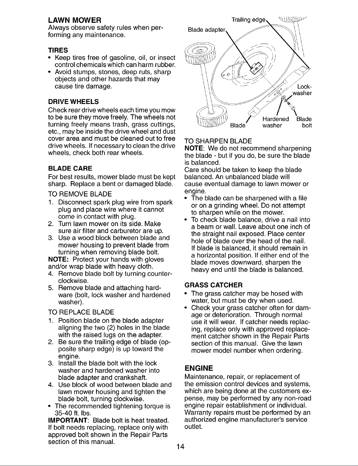
TO REPLACE BLADE
1. Position blade on the blade adapter
aligning the two (2) holes in the blade
with the raised lugs on the adapter.
2. Be sure the trailing edge of blade (op-
posite sharp edge) is up toward the
engine.
3. Install the blade bolt with the lock
washer and hardened washer into
blade adapter and crankshaft.
4. Use block of wood between blade and
lawn mower housing and tighten the
blade bolt, turning clockwise.
• The recommended tightening torque is
35-40 ft. Ibs.
IMPORTANT: Blade bolt is heat treated.
If bolt needs replacing, replace only with
approved bolt shown in the Repair Parts
section of this manual.
Trailing
Lock-
washer
Hardened Blade
Blade washer bolt
TO SHARPEN BLADE
NOTE: We do not recommend sharpening
the blade - but if you do, be sure the blade
is balanced.
Care should be taken to keep the blade
balanced. An unbalanced blade will
cause eventual damage to lawn mower or
engine.
• The blade can be sharpened with a file
or on a grinding wheel. Do not attempt
to sharpen while on the mower.
• To check blade balance, drive a nail into
a beam or wall. Leave about one inch of
the straight nail exposed. Place center
hole of blade over the head of the nail.
If blade is balanced, it should remain in
a horizontal position. If either end of the
blade moves downward, sharpen the
heavy end until the blade is balanced.
GRASS CATCHER
The grass catcher may be hosed with
water, but must be dry when used.
Check your grass catcher often for dam-
age or deterioration. Through normal
use it will wear. If catcher needs replac-
ing, replace only with approved replace-
ment catcher shown in the Repair Parts
section of this manual. Give the lawn
mower model number when ordering.
ENGINE
Maintenance, repair, or replacement of
the emission control devices and systems,
which are being done at the customers ex-
pense, may be performed by any non-road
engine repair establishment or individual.
Warranty repairs must be performed by an
authorized engine manufacturer's service
outlet.
14
Page 15
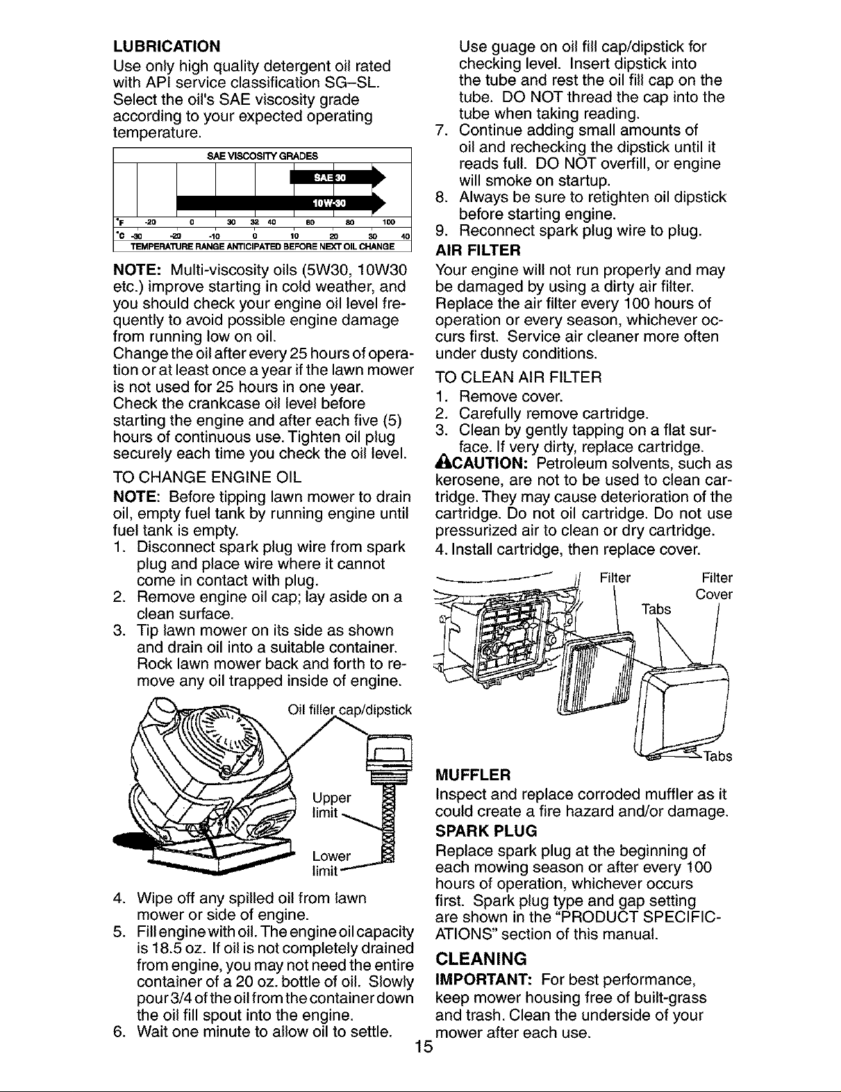
LUBRICATION
Use only high quality detergent oil rated
with API service classification SG-SL.
Select the oil's SAE viscosity grade
according to your expected operating
temperature.
SAE VISCOSITY GRADES
°F _0 0 30 32 40 80 80 100
TEMPERA"RJRE RANGE ANTICIPATED BEFORE NEXT OIL CHANGE
NOTE: Multi-viscosity oils (5W30, 10W30
etc.) improve starting in cold weather, and
you should check your engine oil level fre-
quently to avoid possible engine damage
from running low on oil.
Change the oil after every 25 hours of opera-
tion or at least once a year if the lawn mower
is not used for 25 hours in one year.
Check the crankcase oil level before
starting the engine and after each five (5)
hours of continuous use. Tighten oil plug
securely each time you check the oil level.
TO CHANGE ENGINE OIL
NOTE: Before tipping lawn mower to drain
oil, empty fuel tank by running engine until
fuel tank is empty.
1. Disconnect spark plug wire from spark
plug and place wire where it cannot
come in contact with plug.
2. Remove engine oil cap; lay aside on a
clean surface.
3. Tip lawn mower on its side as shown
and drain oil into a suitable container.
Rock lawn mower back and forth to re-
move any oil trapped inside of engine.
Use guage on oil fill cap/dipstick for
checking level. Insert dipstick into
the tube and rest the oil fill cap on the
tube. DO NOT thread the cap into the
tube when taking reading.
7. Continue adding small amounts of
oil and rechecking the dipstick until it
reads full. DO NOT overfill, or engine
will smoke on startup.
8. Always be sure to retighten oil dipstick
before starting engine.
9. Reconnect spark plug wire to plug.
AIR FILTER
Your engine will not run properly and may
be damaged by using a dirty air filter.
Replace the air filter every 100 hours of
operation or every season, whichever oc-
curs first. Service air cleaner more often
under dusty conditions.
TO CLEAN AIR FILTER
1. Remove cover.
2. Carefully remove cartridge.
3. Clean by gently tapping on a flat sur-
face. If very dirty, replace cartridge.
AqI,CAUTION: Petroleum solvents, such as
kerosene, are not to be used to clean car-
tridge. They may cause deterioration of the
cartridge. Do not oil cartridge. Do not use
pressurized air to clean or dry cartridge.
4. Install cartridge, then replace cover.
Filter Filter
Cover
Tabs
Oil filler cap/dipstick
limit
4. Wipe off any spilled oil from lawn
mower or side of engine.
5. Fill engine with oil. The engine oil capacity
is 18.5 oz. If oil is not completely drained
from engine, you may not need the entire
container of a 20 oz. bottle of oil. Slowly
pour 3/4 ofthe oil from the container down
the oil fill spout into the engine.
6. Wait one minute to allow oil to settle.
MUFFLER
Inspect and replace corroded muffler as it
could create a fire hazard and/or damage.
SPARK PLUG
Replace spark plug at the beginning of
each mowing season or after every 100
hours of operation, whichever occurs
first. Spark plug type and gap setting
are shown in the "PRODUCT SPECIFIC-
ATIONS" section of this manual.
CLEANING
IMPORTANT: For best performance,
keep mower housing free of built-grass
and trash. Clean the underside of your
mower after each use.
15
Page 16

_i,CAUTION: Disconnect spark plug wire
from spark plug and place wire where it
cannot come in contact with plug.
• Clean the underside of your lawn mower
by scraping to remove build-up of grass
and trash.
• Clean engine often to keep trash from
accumulating. A clogged engine runs
hotter and shortens engine life.
• Keep finished surfaces and wheels free
of all gasoline, oil, etc.
• We do not recommend using a garden
hose to clean lawn mower unless the
electrical system, muffler, air filter and
carburetor are covered to keep water
out. Water in engine can result in short-
ened engine life.
CLEAN UNDER DRIVE COVER
Clean under drive cover at least twice a sea-
son. Scrape underside of cover with putty
knife or similar tool to remove any build-up
of trash or grass on underside of drive cover.
_WARNING: To avoid serious injury, before
performing any service and adjustments:
1. Release control bar and stop engine.
2. Make sure the blade and all moving
parts have completely stopped.
3. Disconnect spark plug wire from spark
plug and place wire where it cannot
come in contact with plug.
LAWN MOWER
TO ADJUST CUTTING HEIGHT
See "TO ADJUST CUTTING HEIGHT' in
the Operation section of this manual.
REAR DEFLECTOR
The rear deflector, attached between the
rear wheels of your mower, is provided to
minimize the possibility that objects will be
thrown out of the rear of the mower into
the operator mowing position. If deflector
becomes damaged, it should be replaced.
TO REMOVE DRIVE BELT
1. Disconnect spark plug wire from spark
plug and place wire where it cannot
come in contact with plug.
2. Remove screws retaining drive cover
and remove drive cover from lawn
mower housing (See Figure A).
3. Remove drive cable from anchor, then
detach the drive cable spring from the
idler arm assembly (See Figure B).
Idler arm
pulley
Belt keeper
Drive cable anchor
Drive belt
PIVOT
' \ Housing
\ hole
Figure B
4. Pivot idler arm assembly to slacken
drive belt, then remove drive belt from
drive pulley, belt keepers and idler arm.
5. Turn lawn mower on its side. Make
sure air filter and carburetor are up.
6. Remove screw securing debris shield.
Note that the debris shield has a tab
which fits into a gap in the housing
(See Figure C).
Crankshaft Tab Blade
Housing adapter
hole (pulley
end)
Drive
cover
Figure A
Lawn
mower
housing
16
Trailing edge
Figure C
Hardened
washer
Blade
bolt
Lock-washer
Page 17

7. Use a wood block between blade and
mower housing to prevent blade from
turning when removing blade bolt.
NOTE: Protect your hands with gloves
and/or wrap blade with heavy cloth.
8. Remove blade bolt.
9. Remove blade, attaching hardware
(bolt, lock washer and hardened wash-
er), blade adapter and debris shield as
one assembly.
10. Remove drive belt from blade adapter
and debris shield; discard old belt.
TO REPLACE DRIVE BELT
1. Place new drive belt in the belt retainer
of the debris shield. Be sure to route
belt between belt keepers and through
slot (See Figure D).
Belt
Drive
belt
Debris
Slot shield
Tab
9. Install new drive belt into idler arm
assembly, then around the drive pulley.
Be sure belt is inside of belt keepers
(See Figure B).
NOTE: Pulling on the drive belt (to install
it on the drive pulley) will cause the other
end of the belt to free itself from the debris
shield retainer and properly seat itself in
groove of pulley end of the blade adapter.
10. Reattach drive cable spring to the idler
arm assembly, then reattach drive
cable to anchor.
11. Reattach drive cover with screws previ-
ously removed.
12.Connect spark plug wire to spark plug.
TO ADJUST HANDLE
The handle on your lawn mower has
multiple height positions - adjust to height
that suits you.
1. Remove knob and carriage bolt on left
side of the lower handle.
2. While holding handle assembly, re-
move knob and carriage bolt from right
side. Align hole in handle with desired
hole in handle bracket, then reassem-
ble bolt and knob and tighten securely.
3. Align left side of handle with same po-
sitioning hole as right side and secure
with bolt and knob.
Bolt
Knob_
Figure D
2. Route the other end of the new drive
belt through hole in housing.
3. Reattach debris shield to housing with
screw previously removed. Be sure tab
of debris shield is in gap of housing.
4. Position blade on the blade adapter
aligning the two (2) holes in the blade
with the raised lugs on the adapter.
5. Be sure the trailing edge of blade (op-
posite sharp edge) is up toward the
engine (See Figure C).
6. Install the blade bolt with the lock
washer and hardened washer into
blade adapter and crankshaft.
7. Use block of wood between blade and
lawn mower housing and tighten the
blade bolt, turning clockwise.
• The recommended tightening torque is
35-40 ft. Ibs.
IMPORTANT: Blade bolt is heat treated.
If bolt needs replacing, replace only with
approved bolt shown in the Repair Parts
section of this manual.
8. Return mower to upright position.
Hi
ENGINE
Maintenance, repair, or replacement of the
emission control devices and systems, which
are being done at the customers expense,
may be performed by any non-road engine
repair establishment or individual. Warranty
repairs must be performed by an authorized
engine manufacturer's service outlet.
17
Page 18

ENGINE SPEED
Your engine speed has been factory set.
Do not attempt to increase engine speed
or it may result in personal injury. If you
believe that engine is running too fast or
too slow, take your mower to a Sears or
other qualified service center for repair
and adjustment.
CARBURETOR
Your carburetor is not adjustable. If your
engine does not operate properly due to sus-
pected carburetor problems, take your lawn
mower to a Sears or other qualified service
center for repair and/or adjustment.
IMPORTANT: Never tamper with the
engine governor, which is factory set
for proper engine speed. Overspeeding
the engine above the factory high speed
setting can be dangerous. Ifyou think
the engine-governed high speed needs
adjusting, contact a Sears or other
qualified service center, which has proper
equipment and experience to make any
necessary adjustments.
Immediately prepare your lawn mower for
storage at the end of the season or if the
unit will not be used for 30 days or more.
LAWN MOWER
When lawn mower is to be stored for a
period of time, clean it thoroughly, remove
all dirt, grease, leaves, etc. Store in a
clean, dry area.
1. Clean entire lawn mower (See
"CLEANING" in the Maintenance sec-
tion of this manual).
2. Lubricate as shown in the Maintenance
section of this manual.
3. Be sure that all nuts, bolts, screws, and
pins are securely fastened. Inspect
moving parts for damage, breakage
and wear. Replace if necessary.
4. Touch up all rusted or chipped paint
surfaces. Be sure to sand surface
lightly before painting.
HANDLE
You can fold your lawn mower handle for
storage.
NOTE: The upper handle has an "anti-
fold" bracket located on the left side of the
handle. This bracket prevents the upper
handle from folding forward, which helps
protect control cable(s) from damage.
1. Loosen the two (2) handle knobs on
sides of the upper handle and allow
handle to fold down to the rear.
2. Remove the two (2) handle knobs and
carriage bolts on sides of the lower
handle and pivot entire handle as-
sembly forward and allow it to rest on
mower.
3. Reinstall knobs and carriage bolts to
lower handle or handle brackets for
safe keeping.
• When setting up your handle from the
storage position, you must manually
lock lower handle into mowing position.
IMPORTANT: When folding the handle for
storage or transportation, be sure to fold it
as shown or you may damage the control
cables.
Operator presence
control bar
Lower
Mowing
position
Knob_
Handle'
bracket
_- Bolt
18
Page 19

ENGINE
FUEL SYSTEM
IMPORTANT: It is important to prevent
gum deposits from forming in essential
fuel system parts such as carburetor, fuel
filter, fuel hose, or tank during storage.
Also, alcohol blended fuels (called gasohol
or using ethanol or methanol) can attract
moisture which leads to separation and
formation of acids during storage. Acidic
gas can damage the fuel system of an
engine while in storage.
• Empty the fuel tank by starting the en-
gine and letting it run until the fuel lines
and carburetor are empty.
• Never use engine or carburetor cleaner
products in the fuel tank or permanent
damage may occur.
• Use fresh fuel next season.
NOTE: Fuel stabilizer is an acceptable
alternative in minimizing the formation of
fuel gum deposits during storage. Add
stabilizer to gasoline in fuel tank or stor-
age container. Always follow the mix ratio
found on stabilizer container. Run engine
at least 10 minutes after adding stabilizer
to allow the stabilizer to reach the car-
buretor. Do not empty the gas tank and
carburetor if using fuel stabilizer.
ENGINE OIL
Drain oil (with engine warm) and replace
with clean engine oil. (See "ENGINE" in
the Maintenance section of this manual).
CYLINDER
1. Remove spark plug.
2. Pour one ounce (29 ml) of oil through
spark plug hole into cylinder.
3. Pull starter handle slowly a few times
to distribute oil.
4. Replace with new spark plug.
OTHER
• Do not store gasoline from one season
to another.
• Replace your gasoline can if your can
starts to rust. Rust and/or dirt in your
gasoline will cause problems.
• If possible, store your unit indoors and
cover it to protect it from dust and dirt.
• Cover your unit with a suitable protec-
tive cover that does not retain moisture.
Do not use plastic. Plastic cannot
breathe, which allows condensation to
form and will cause your unit to rust.
IMPORTANT: Never cover mower while
engine and exhaust areas are still warm.
• I,CAUTION: Never store the lawn mower
with gasoline in the tank inside a building
where fumes may reach an open flame
or spark. Allow the engine to cool before
storing in any enclosure.
TROUBLESHOOTING - See appropriate section in manual unless directed
to a Sears Parts & Repair Center.
PROBLEM CAUSE CORRECTION
Does not start 1. Dirty air filter. 1. Clean/replace air filter.
2. Out of fuel.
3. Stale fuel.
2_
Fill fuel tank.
3.
Empty fuel tank and refill tank
with fresh, clean gasoline.
4. Water infuel.
4.
Empty fuel tank and refill tank
with fresh, clean gasoline.
5. Spark plug wire is
5.
Connect wire to plug.
disconnected.
6. Bad spark plug.
7. Loose blade or broken
blade adapter.
8. Control bar in released
position.
9. Control bar defective.
10. Fuel valve lever (if so
equipped) in OFF position.
11.Weak battery (if equipped).
12. Disconnected battery
6.
Replace spark plug.
7.
Tighten blade bolt or
replace blade adapter.
8. Depress control bar to
handle.
9. Replace control bar.
10.Turn fuel valve lever
to the ON position.
11.Charge battery.
12.Connect battery to engine.
connector (if equipped).
19
Page 20

TROUBLESHOOTING - See appropriate section in manual unless directed
to a Sears Parts & Repair Center.
PROBLEM CAUSE
CORRECTION
Loss of power 1. Rear of mower housing or
blade dragging in grass.
2. Cutting too much grass.
3. Dirty air filter.
4. Buildup of grass, leaves,
and trash under mower.
5. Too much oil in engine.
6. Walking speed too fast.
Poor cut -
uneven
Excessive
vibration
Starter rope
hard to pull
1. Worn, bent or loose blade.
2. Wheel heights uneven.
3. Buildup of grass, leaves
and trash under mower.
1. Worn, bent or loose blade.
2. Bent engine crankshaft.
1. Engine flywheel brake is on
when control bar is released.
2. Bent engine crankshaft.
3. Blade adapter broken.
4. Blade dragging in grass.
1. Raise cutting height.
2. Raise cutting height.
3. Clean/replace air filter.
4. Clean underside of mower
housing.
5. Check oil level.
6. Cut at slower walking speed.
1. Replace blade. Tighten
blade bolt.
2. Set all wheels at same
height.
3. Clean underside of
mower housing.
1. Replace blade. Tighten
blade bolt.
2. Contact a Sears or other
qualified service center.
1. Depress control bar to
upper handle before
pulling the starter rope.
2. Contact a Sears or other
qualified service center.
3. Replace blade adapter.
4. Move lawn mower to cut
grass or to hard surface.
Grass catcher 1. Raise cutting height.
not filling 2. Replace blade.
(If so equipped) 3. Clean grass catcher.
Hard to push 1. Raise cutting height.
Loss of drive
or slowing of
drive speed
1. Cutting height too low.
2. Lift on blade worn off.
3. Catcher not venting air.
1. Grass is too high or wheel
height is too low.
2. Rear of mower housing or
blade dragging in grass.
3. Grass catcher too full.
4. Handle height position not
right for you.
1. Belt wear.
2. Belt off of pulley.
3. Drive cable worn or broken.
4. "Loose" drive control system.
2. Raise rear of mower housing
one (1) setting higher.
3. Empty grass catcher.
4. Adjust handle height to suit.
1. Check/replace drive belt.
2. Check/reinstall drive belt.
3. Replace drive cable.
4. Adjust drive control.
20
Page 21

Garantia ......................................................... 21
Reglas de Seguridad ................................ 21-23
Especificaciones del Producto ....................... 23
Montaje / Pre-Operaci6n .......................... 24-25
Operaci6n ................................................. 26-31
Mantenimiento .......................................... 32-35
GARANTiA LIMITADA DE DOS AI_IOS PARA LA SEGADORA A MOTOR CRAFTSMAN
Per dos (2) aSos, a partir de la fecha de compra, cuando esta Segadora Craftsman se mantenga,
lubrique y afine segSn las instrucciones para la operaci6n y el mantenimiento en el manual del
dueSo, Sears repararA gratis todo defecto en el material y la mane de obra.
Si la Segadora Craftsman se usa para fines comerciates o de arriendo, esta garantia s61o se aplica
per noventa (90) dias a partir de la fecha de compra.
Esta Garantia no cubre:
• Articulos que se desgastan durante el use normal tales come las cuchillas segadoras rotatorias,
los adaptadores de la cuchilla, las correas, los filtros de aire y las bujias.
• Reparaciones necesarias debido al abuse o a la negligencia del operador, incluy_ndose a los
cigee5ales doblados y a la falta de mantenimiento del equipo segSn las instrucciones que se
inctuyen en el manual del due5o.
El servicio de garantia esta disponible al devolver la segadora a motor Craftsman al Centre de
Servicio Sears mas cercano en los Estados Unidos. Esta garantfa se apiica solamente mientras el
producto este en use en los Estados Unidos.
Esta Garanfia le otorga derechos legales especfficos, y puede que tambi6n tenga otros derechos
que varfan de estado a estado.
Sears, Roebuck and Co., D/817WA, Hoffman Estates, IL 60179 USA
Programa de Mantenimiento ......................... 32
Servicio y Adjustes ................................... 35-37
Almacenamiento ....................................... 37-38
Identificaci6n de problemas ...................... 38-39
Partes de repuesto .................................. 40-47
Servicio Sears .................................. Contratapa
IMPORTANTE: Esta maquina cortadaora es capaz de amputar las manes y los manes y los pies y
de lanzar objetos. Si no se observan las instrucciones de seguridad siguientes se pueden producir
lesiones graves o la muerte.
_Busque este simbolo que se_ala las precau-
clones de seguridad de importancia. Quiere
decir- iiiATENCION!!! iiiESTE ALERTO!!!
SU SEGURIDAD ESTA COMPROMETIDA.
d_haLDVERTENCI.,&:Siempre desconecte el
alambre de la bujfa y p6ngato donde no pueda
entrar en contacto con la bujfa, para evitar et
arranque per accidente, durante la preparaci6n,
el transporte, el ajuste o cuando se hacen
reparaciones.
_DVERTENClA: Los bornes, terminales y
accesorios relatives de la bateria contienen
plomo o compuestos de plomo, productos
qu[micos conocidos en el Estado de California
come causa de cancer y defectos al nacimiento
u otros daSos reproductivos. Lavar lae manes
despu_e de manipularloe.
_[ILPRECAUCI(_N: El tube de escape del motor,
algunos de sus constituyentes y algunos com-
ponentes del vehfculo contienen o desprenden
productos qufmicos conocidos en el Estado de
California come causa de cancer y defectos at
nacimiento u otros daSos reproductivos.
_PRECAUCl0N: El silenciador y otras
piezas del motor llegan a sre extremadamente
calientes durante la operaci6n y siguen siendo
calientes despu_s de que el motor haya parade.
Para evitar quemaduras severas, permanezca
lejos de estas Areas.
21
Page 22

I. OPERAClON
• Antes de empezar, debe familiarizarse comple-
tamente con los controles y el uso correcto de
la maquina. Para esto, debe leer y comprender
todas las instrucciones que aparecen en la ma-
quina yen los manuales de operaci6n.
• No ponga las manos o los pies cerca o
debajo de las partes rotatorias. Mant6ngase
siempre lejos de la abertura de la descarga.
• Permita que solamente las personas re-
sponsables que est6n familiarizadas con las
instrucciones operen la mAquina.
• Despeje el Area de objetos tales como pie-
dras, juguetes, alambres, huesos, palos, etc.
que pueden ser recogidos y lanzados por las
cuchillas.
• AsegSrese que el Area no se hallen per-
sonas, antes de segar. Pare la mAquina si
alguien entra en el Area.
• No opere la maquina sin zapatos ocon sanda-
lias abiertas. P6ngase siempre zapatos s61idos.
• No tire de la segadora hacia atrAs a menos
que sea absolutamente necesado. Mire
siempre hacia abajo y hacia detrAs antes y
mientras que se mueve hacia atrAs.
• No opere la segadora sin los respectivos
resguardos, las placas, el recogedor de
c6sped u otros aditamentos dise ados para
su protecci6n y seguridad.
• Refi_rase alas instrucciones det fabricante
para el funcionamiento e instataci6n de
accesorios. Use t_nicamente accesorios
aprobados por el fabricante.
• Detenga la cuchilla o las cuchillas cuando cruce
por catzadas, calles o caminos de grava.
• Parar el motor cada vez que se abandona el
aparato, antes de limpiar la segadora o de
remover residuos del tubo.
• Apagar el motor y esperar hasta que las
cuchillas est_n completamente paradas
antes de remover el receptor de hierba.
• Segar solamente con luz del dfa o con una
buena luz artificial.
• No opere la mAquina bajo la influencia del
alcohol o de las drogas.
• Nunca opere la maquina cuando la hierba
est_ mojada. Asegt]rese siempre de tener
buena tracci6n en sus pies; mantenga el
mango firmemente y camine; nunca corra.
• Desconectar el mecanismo de propulsi6n
aut6noma o el embrague de transmisi6n en
las segadoras que Io tienen antes de poner
en marcha el motor.
• Si el equipo empezara a vibrar de una
manera anormal, pare el motor y revise de
inmediato para averiguar la causa. General-
mente la vibraci6n suele indicar que existe •
alguna averia.
• Siempre use gafas de seguridad o anteojos con •
protecci6n lateral cuando opere la segadora.
II. OPERACION SOBRE LAS CUESTAS
Los accidentes ocurren con mAs frecuencia en
las cuestas. Estos accidentes ocurren debido a
resbaladas o caidas, las cuales pueden resultar •
en graves lesiones. Operar la recortadora en
cuestas requiere mayor concentraci6n. Si se
siente inseguro en una cuesta, no la recorte.
22
HACER:
• Puede recortar a trav6s de la superficie de
la cuesta, nunca hacia ardba y hacia abajo.
Proceda con extrema precauci6n cuando
cambie de direcci6n en las cuestas.
• Renueva todos los objetos extraSos, tales
como guijarros, ramas, etc.
• Debe prestar atenci6n a hoyos, baches o
protuberancias. Recuerde que la hierba alta
puede esconder obstAculos.
NO HACER:
• No recorte cerca de pendientes, zanjas o
terraplenes. El operador puede perder la
tracci6n en los pies o el equilibrio.
• No recorte cuestas demasiado inclinadas.
• No recorte en hierba mojada. La reducci6n
en la tracci6n de la pisada puede causar
resbalones.
III. NINOS
Se pueden producir accidentes trAgicos si el
operador no presta atenci6n a la presencia
de los niSos. A menudo, los niSos se sienten
atraidos por la maquina y por la actividad de
la siega. Nunca suponga que los niSos van a
permanecer en el mismo lugar donde los vio
por _ltima vez.
• Mantenga a los niSos alejados del Area de
la siega y bajo el cuidado estricto de otra
persona adulta responsable.
• Est6 alerta y apague la maquina si hay niSos
que entran at Area.
• Antes y cuando este retrocediendo, mire
hacia atrAs y hacia abajo para verificar si hay
niSos pequeSos.
• Nunca permita que los ni_os operen la mAquina.
• Tenga un cuidado extra cuando se acerque
a esquinas donde no hay visibilidad, a los
arbustos, Arboles u otros objetos que pueden
interferir con su linea de visi6n.
IV. SERMIClO
• Tenga cuidado extra al manejar la gasolina y
los demAs combustibles. Son inflamables y
los gases son explosivos.
- Use solamente un envase aprobado.
- Nunca remueva la tapa del dep6sito de
gasolina o agregue combustible con el mo-
tor funcionando. Permita que el motor se
enfrfe antes de volver a pone combustible.
No fume.
- Nunca vuelva a poner combustible en la
mAquina en recintos cerrados.
- Nunca almacene la mAquina o el envase
del combustible dentro de algt]n lugar en
donde haya una llama expuesta, tat como
la del calentador de agua.
Nunca haga funcionar una mAquina dentro
de un Area cerrada.
Nunca haga ajustes o reparaciones mientras
el motor est_ en marcha. Desconecte et
cable de la bujfa, y mant_ngalo a cierta
distancia de 6sta para prevenir un arranque
accidental.
Mantenga las tuercas y los pernos, espe-
cialmente los pernos del accesorio de la
cuchilla, apretados y mantenga el equipo en
buenas condiciones.
Page 23

• Nuncamanipuledeformaindebidalos
dispositivosdeseguridad.Controleregular-
mentesufuncionamientocorrecto.
• Mantengalam&quinalibredehierba,hojas
uotrasacumulacionesdedesperdicio.
Limpielosderramesdeaceiteo combustible.
Permitaquelam&quinaseenfrfeantesde
almacenarla.
• Pareeinspeccioneelequiposilepegaa un
objeto.Rep&relo,siesnecesario,antesde
hacerloarrancar.
• Enningt]ncasohayqueregularlaalturade
lasruedasmientrasel motorestAenmarcha.
Nt_mero de Serie:
Fecha de Compra:
Capacidad y Tipo de Gasolina: 1.0 Cuartos (Regular sin PIomo)
Capacidad de Aceite: 18.50nzas
Tipo de Aceite (API SG-SL): SAE 30 (Debajo 0°C/32°F) o SAE 10W30
Bujfa (Abertura: .030") NGK BPR6ES
Tolerancia de VAIvula (+ 0.004 mm) Admisi6n: 0.015 mm; Descarga: 0.020 mm
Torsi6n del Perno de la Cuchilla: 35-40 ft. Ibs.
El nSmero del nodelo y el de serie se encuentran en la calcomania adjunta a la parte trasera
de ta caja de la segadora. Debe registrar tanto el nQmero de serie come la fecha de compra y
mantengatos en un lugar seguro para refencia en el futuro.
• Loscomponentesdelreceptordelahierba
vansujetosadesgaste,daSosydetedoro,
quepuedenexponerlaspartesenmov-
imientoopermitirqueobjetosseandispara-
dos.Controlarfrecuentementeycuandosea
necesadosustituirconpartesaconsejadas
perelfabricante.
• Lascuchillasdelasegadoraest#,nafiladasy
puedencortar.Cubrirlashojasollevarguantes,
y utilizarprecaucionesespecialescuandose
efectt_amantenimientosobrelasmismas.
• Nocambieelajustedelreguladordelmotor
niexcedasuvelocidad.
Acuerdos de Protecci6n para la Reparaci6n
Congratulaciones por su buena compra. Su
nuevo producto Craftsman® estA diseSado
y fabricado para funcionar de modo fiable por
muchos aSos. Pero como todos los productos,
puede necesitar alguna reparaci6n de tanto
en tanto. En este caso tener un Acuerdo de
Protecci6n para la Reparaci6n puede hacerles
ahorrar dinero y fastidios.
Compre ahora un Acuerdo de ProtecciSn para
la ReparaciSn y prot&gese de molestias y gas-
tos inesperados.
Un Acuerdo incluye los punto$ $iguientes:
• Servicio experto de nuestros 12.000 espe-
cialistas profesionales en la reparaci6n.
• Servicio ilimitado sin cargo alguno para
las partes y ta mano de obra sobre todas las
reparaciones garantizadas.
• Sustitucion del producto si su producto
garantizado no puede ser arreglado.
• Descuento de110% sobre el precio cor-
riente del servicio y de las partes relativas al
servicio no cubiertas por el acuerdo; tambi_n
el 10% menos sobre el precio corriente de
un control de mantenimiento preventive.
• Ayuda rapida por telefono - soporte tele-
f6nico per parte de un t6cnico Sears sobre
productos que requieren un arreglo en casa,
y adem#,s una programaci6n sobre los a
reglos mAs convenientes.
Cuando se ha comprado el Acuerdo, basta con
una Ilamada telef6nica para programar el servi-
cio. Puede Ilamar cuando quiera, alia y noche o
fijar en linea una cita para obtener el servicio.
Sears tiene m#,s de 12.000 especialistas
profesionales en la reparaci6n, que tienen
acceso a mAs de 4.5 millones de partes y
accesorios de calidad. Este es el tipo de
profesionalidad con que puede contar para
ayudar a alargar la vida det producto que acaba
de comprar, por muchos aSos. iCompre hoy su
Acuerdo de Protecci6n para la Reparaci6n!
Se aplican algunas limitaciones y exclu-
siones. Para conocer los precios y tener
mas informacion, Ilame al 1-800-827-6655.
Servicio de Instalacibn Sears
Para la instalaci6n profesional Sears de
aparatos de casa, puertas de garaje,
calentadores de agua y otros importantes
artfculos para ta casa, en U.S.A. Ilamar a
1-8OO-4-MY-HOME®.
23
Page 24

Estos accesorios estaban disponibles cuando se produjo la segadora. No son facilitados junto al
cortacesped. Tambi6n est&n disponibles en la mayorfa de las tiendas de Sears yen los centros de
servicio. AIgunos de estos accesorios tat vez no se apliquen a su segadora.
RENDIMIENTO DE LA SEGADORA
DESVIADOR
DE RECORTES
PAPA SEGADOPAS
CON DESCARGA
TPASEPA
ESTABILI-
ZADORES
\\ RECOREDOR
_\\ \\\ PAPA
SEGADOPAS
CON DESCARGA
TRASEPA
RECOREDOR
PARA
SEGADOPAS
CON DESCARGA
LATERAL
MANTENIMIENTO DE LA SEGADORA
SILENCIADORES FILTROS DE AIRE BUJfAS
ADAFI'A_RES ACEI_
CORREAS CUCHILLAS DE CUCHILLA RUEDAS DI=L MOTOR
Lea estas instrucciones y este manual comple-
tamente antes de tratar de montar u operar su
segadora nueva.
IMPORTANTE: Este cortac_sped viene SIN
ACEITE O GASOLINA en el motor.
Su segadora nueva ha sido montada en la
f&brica con la excepci6n de aquellas partes que
se dejaron sin montar pot razones de env[o.
Todas tas partes como las tuercas, tas arande-
las, los pernos, etc., que son necesadas para
completar el montaje han sido colocadas en la
bolsa de partes. Para asegurarse que su sega-
dora funcione en forma segura y adecuada,
todas las partes y los articulos de ferreteria que
se monten tienen que ser apretados segura-
mente. Use las herramientas correctas, como
sea necesario, para asegurar que se aprieten
adecuadamente.
PARA REMOVER LA SEGADORA DE
LA CAJA DE CARTON
1. Remueva las partes sueltas que se inctuyen
con la segadora.
2. Corte las dos esquinas de los extremos
de la caja de cartSn y tienda el panel del
extremo piano.
3. Remueva todo el material de empaque, ex-
cepto la cuSa entre el mango superior y 61
inferior,y la cuSa que sujeta la barra de los
control que exige la presencia del operador
junto con et mango superior.
4. Haga rodar la segadora hacia afuera de la
caja de cartSn y revisela cuidadosamente
para vedficar si todavia quedan partes
sueltas adicionates.
24
Page 25

COMO PREPARAR SU SEGADORA
PARA DESDOBLAR EL MANGO
IMPORTANTE: Despliegue el mango con
mucho cuidado para no pellizcar o da_ar los
cables de control.
1. Levante la secci6n del mango inferior hasta
la posici6n de operaci6n y alinee el agujero
en 6ste con uno de los agujeros para deter-
minar la altura en el puntal del mango.
2. Inserte el perno del mango a trav6s de 6ste
y del puntal y asegt_relo con ta manilla.
3. Repita el procedimiento para el lado
opuesto del mango.
4. Levante la secci6n del mango superior
hasta la posici6n de operaci6n, remueva la
cuSa protectora y apriete las manillas del
mango en forma segura.
5. Remueva et material de empaque de alred-
edor de la barra de control.
El mango de la segadora puede ajustarse
segt_n le acomode para segar. Refi_rase a
"AJUSTE DEL MANGO" en la secci6n de
Servicio y Ajustes de este manual.
Barra de control que
Mango superior
la presencia del operador
PARA MONTAR EL RECOGEDOR DE
ClaSPED
1. Destizar el saco de la hierba sobre el
armaz6n. Asegurarse de que el mango
trasero est6 arriba (el mismo lade que el
mango delantero) y la abrazadera abajo.
2. Destice los sujetadores de vinilo sobre el
bastidor.
AMISO: Si los sujetadores de vinilo estAn muy
duros, m6talos en agua catiente por algunos
minutes. Si se moja la bolsa, d6jela que se
seque antes de usarla.
3. Cerrar la puerta del dep6sito de hierba.
AMISO: Cuando est& completamente cerrada,
la puerta se cerrar& con un disparo sobre el
armaz6n y los elementos de fijaci6n en vinilo.
j
Mango
posterior
Correa
Mango Inferior
LEVANTAR
Manilla
Soporte
de mango
Mango
anterior
Posici6n
para segar
El bastidor
del
Perno recogedo_,,,,_
Sujetadores
de vinilo
PARA INSTALAR LOS ACCESORIOS
Su segadora fue enviada Iista para usarse
como una acolchadora de capa vegetal. Para
convertirla de modo que pueda ensacar o
descarga, refi6rase a "PARA CONVERIR LA
SEGADORA" en la secci6n de Operaci6n de
este manual.
25
Page 26

FAMILIARICESE CON SU SEGADORA
LEA ESTE MANUAL DEL DUENO Y LAS REGLAS DE SEGURIDAD ANTES DE OPARAR SU
SEGADORA. Compare las ilustraciones con su segadora para familiarizarse con la ubicaci6n de
los diversos controles y ajustes. Guarde este manual para referencia en el futuro.
Estos simbolos pueden apareser sobre su segadora o en la literatura proporcionada con el
producto. Aprenda y comprenda sus significados.
A'n'ENCI(_N O MOTOR MOTOR RAPIDO LENTO ESTRANGU COM- ACEITE PELIGRO, GUARDE LAS
ADVERTENCIA ENCENDIDO APAGADO LACI(SN BUSTIBLE MANOS Y LOS PIES LEJOS
Barra de control que exige la
presencia del operador
. Palanca de control de la impulsi6n
Cord6n
arrancador
Recogedor
de c6sped
Tapa del deposito de
aciete det motor con
varilla indicadora de nivel
Silenciador
Puerta de la acolchadora
Cubierta de la impulsi6n
Tapa del deposito
Mango del ajustador
punto
V_,lvula del
combustible
Filtro
Caja
IMPORTANTE: Este cortac_sped viene SIN ACEITE O GASOLINA en motor.
CUMPLE CON LOS REQUISITOS DE SEGURIDAD DE LA CPSC
Las segadoras a motor, que se conducen desde la parte de atr_s, rotatorias, Sears, cumplen con
los est&ndares de seguridad del American National Standards Institute y de la U.S. Consumer
Product Safety Commission. La cuchilla gira cuando el motor estA funcionando.
Barra de control que exige la presencia del
operador - tiene que sujetarse abajo, junto
con el mango, para hacer arrancar el motor.
Su61tela para parar el motor.
Palanca de control de la impulsion - se usa
para enganchar la segadora para movimiento
Cordon arrancador - se usa para hacer ar-
rancar el motor.
Puerta de la acolchadora - permite la conver-
si6n para la operaci6n de descarga o ensacado.
Mango del ajustador de un duel punto - se usa
para ajustar la attura de corte de la segadora.
hacia adelante impulsada a motor.
26
Page 27

La operaci6n de cualquier
segadora puede hacer que
satten objetos extraSos dentro de
sus ojos, Io que puede producir
daSos graves en _stos. Siempre
use anteojos de seguridad o protecci6n para
los ojos mientras opere su segadora o cuando
haga ajustes o reparaciones. Recomendamos
gafas o una mascara de seguridad de visi6n
amplia de seguridad usada sobre las gafas.
COMO USAR SU SEGADORA
VELOCIDAD DEL MOTOR
La velocidad del motor se estableci6 en la f_-
brica para un rendimiento 6ptimo. La velocidad
no se puede ajustar.
_NTROL DE ZONA DEL MOTOR
PRECAUClON: Las regulaciones federales
exigen que se instale un control para el motor
en esta segadora para reducir a un mfnimo el
riesgo de lesionarse debido al contacto con la
cuchilla. Por ningt]n motivo trate de eliminar
la funci6n del control del operador. La cuchilla
gira cuando el motor est& funcionando.
• Su segadora viene equipada con una barra
de controles que exigen la presencia del
operador, Io que requiere que el operador
est6 detrAs del mango de la segadora para
hacerla arrancar y operarla.
CONTROL DE LA IMPULSION
• La autopropulsi6n se controla manteniendo
la patanca de mando operador presente
abajo hacia el mango y tirando ta palanca de
accionamiento atr&s hacia el mango. Cuanto
m_,s lejos se tira la patanca hacia el mango,
m_s r#,pida ira la unidad.
• El movimiento hacia adelante se detiene
cuando sea la palanca de mando operador
presente o la palanca de accionamiento se
sueltan. Para detener el movimiento hacia
adelante sin apagar el motor, soltar s61o
la patanca de accionamiento. Mantener la
palanca de mando operador presente abajo
contra el mango para continuar a cortar sin
autopropulsi6n.
AMISO: Si despu6s haber desenganchado de la
palanca de control, la segadora no roda hacia
atr_,s, empuje ta segadora un poco hacia adelante
para desenganchar las ruedas de la impulsi6n.
• Para mantener et mando conectado cuando
se da la vuelta a una esquina, empujar el
mango para levantar las ruedas delanteras
del terreno mientras se gira la cortadora.
Barra de control que ,perador
AJUSTE DEL MANDO
Ocasionalmente, el sistema de mando puede
"aflojarse', provocando una disminuci6n de la
velocidad. Hay un bot6n en la parte trasera de
la sede del mando para apretar la tensi6n del
cable. Preceder de la siguiente manera:
1. Apagar la motor y desconectar el cable de
bujia de la bujfa.
2. Tirar el bot6n en la parte inferior del mando
de transmisi6n, luego empujarlo otra vez.
3. Opera la segadora para versi la vetoci-
dad del mecanismo ha aumentado. Si no
hay aumento, significa que es necesario
sustituir la correa de transmisi6n.
PARA AJUSTAR LA ALTURA DE CORTE
Las dos ruedas traseras se ajustan a tray,s
de una t_nica patanca en la rueda trasera
izquierda.
• Tire de la palanca de ajustes hacia la rueda.
Levante la segadora, mueva la palanca hasta
delante a la posici6n deseada. Para bajar la
segadora, mueva la palanca hacia la reta-
guardia.
AVISO: Existen siete (7) posiciones de ajuste
de la altura para las ruedas traseras.
Las dos ruedas delanteras se ajustan a trav6s
come sigue:
1. Remueva la rueda, el perno y los art[culos
de ferreterfa y vuelva a montarlos en el
agujero de ajuste deseado.
2. Vuelva a instalar los componentes de la
rueda en el mismo orden en que se encon-
traban antes de removerlos. Apri6telos en
forma segura.
AVISO: Existen siete (7) agujeros de ajuste de
la attura para las ruedas delanteras. Asegurarse
de que ambas ruedas est6n en el mismo
agujero.
IMPORTANTE: Asegurarse de que las dos
ruedas delanteras y traseras est6n reguladas a
la misma altura.
PALANCA
HACIA ATR,_S
PARA BAJAR EL
CORTACESPED
Arandela
Anill
Teurca de
Mango
PALANCA HACIA
ADELANTE PARA
LEVANTAR EL
CORTACESPED
Varilla de seguridad
(posici6n de "reuda
libre")
"Perno
/arilla de seguridad
(posici6n de
"seguridad")
PARA
Bot6n ajuste ENGANCHAR EL
(en la parte CONTROL DE LA
trasera) IMPULSION
Control
la impulsi6r
CONTROL DE LA
IMPULSION
DESENGANCHADO 27
Page 28

FUNCIONAMIENTO RUEDA ORIENTABLE
Las ruedas detanteras se pueden "bloquear" en
posici6n o fijar en "rueda libre" para maniobrar
de mode m&s _,gil. Colocando los pedales de
enclavamiento en los agujeros externos de las
abrazaderas de ajuste "bloquea" las ruedas
delanteras. De la misma manera, colocando
los pedales de enclavamiento en los agujeros
internos de las abrazaderas de ajuste permite
alas ruedas delanteras girar libremente ("rueda
libre').
• Levantar el pedal de enclavamiento
hasta que et terminal m&s delantero libera la
abrazadera de ajuste, luego pivotar el pedal
de enclavamiento en la posici6n deseada.
IMPORTANTE: Las ruedas delanteras tienen
que ser "bloqueadas" en posici6n cuando se
trabaja en un terreno pendiente. Preceder de un
lade al otro de los terrenos pendientes: nunca
de arriba abajo.
PARA CONVERTIR LA SEGADORA
Su segadora rue enviada lista para usarse
como acolchadora de capa vegetal. Para con-
vertirla a una operaci6n de ensacado posterior
o de descargar lateral:
SEGADORAS CON DESCARGA TRASERA
• Quitar el pomo que fija ta puerta del acaba-
dor al bastidor del cortac_sped.
• Abrir la puerta del acabador e introducir
las leng0etas det tube de descarga en la
apertura de la bdda de la articulaci6n y
colocar la parte trasera del tubo sobre el
pasador roscado.
Para convertir en ta operaci6n de acabado,
quitar el dep6sito de hierba y el canal de
eyecci6n. Fijar la puerta del acabador al
bastidor del cortac_sped a trav_s del pomo.
Para convertir en la operaci6n de descarga,
quitar el dep6sito de hierba y el canal de
eyecci6n. Instalar et deflector de descarga
lateral y fijarlo al bastidor del cortac6sped a
trav_s del pomo.
posterior
del mangoinferior
Elrecogedor
c6sped
redonda
inclinado de Manilla
la descarga
Pasador
roscado
LengQetas del tubo de descarga
iS "'"
_c kT\
_oporte de ar_ct'culacion) Fuerta de 'al_co'ch_c'ora
• Fijar la parte trasera del canal de descarga at
bastidor del cortac6sped a trav6s del pomo.
• Colocar el mango trasero det dep6sito de
hierba en la alzaprima del mango inferior del
cortac6sped como mostrado.
• Atzar la puerta redonda del canal de eyec-
ci6n y colocar el dep6sito de hierba en el
canal de eyecci6n.
AVISO: Asegurarse de que la puerta redonda
del canal de eyecci6n se apoye en el dep6sito
de hierba como mostrado.
• Ahora el cortac_sped est_ listo para la oper-
aci6n de ensacado trasero.
Puerta de la acolchado
SEGADORAS CON DESCARGA LATERAL
• Hay que quitar el dep6sito de hierba y el
canal de eyecci6n.
• Abrir la puerta de la puerta del acabador e
instalar la parte delantera del deflector de
descarga lateral debajo la puerta y colocar el
parte trasero en la esp&rrago fileteado.
• Fijar la parte trasera del deflector de des-
carga lateral al bastidor del cortac_sped a
trav_s del pomo.
• Ahora el cortac_sped estA listo para la oper-
aci6n de descarga.
• Para convertir a la operaci6n de acabado,
hay que quitar el deflector de descarga lat-
eral y fijar la puerta del acabador al bastidor
del cortac_sped a trav_s del pomo.
• Para convertir en la operaci6n de ensacado
trasero, hay que quitar el deflector de des-
carga lateral; instalar el canal de eyecci6n y
el dep6sito de hierba y fijar el canal de des-
carga al bastidor del cortac_sped a trav_s
del pomo.
28
Page 29

Puerta de la •Manilla
roscado
PARA VACIAR EL RECOGEDOR DE ClaSPED
1. Abierto la puerta redonda del canal incli-
nado de ta descarga para mover ta cuerda
del arrancador hacia fuera y lejos des de el
recogedor de c6sped.
\
\ Mango
\
Desviador de'
la descarga
PASOS SIMPLES DE RECORDAR
CUANDO CONVIERTA SU SEGADORA
PARA ACOLCHAMIENTO -
1. El dep6sito de hierba, el canal de eyecci6n
y el deflector de descarga lateral quitados.
2. La puerta del acabador fijada al bastidor del
cortac6sped a trav6s del pomo.
PARA ENSACAMIENTO TRASERO -
1. Deflector de descarga lateral quitado.
2. El dep6sito de hierba y el canal de eyecci6n
instalados con el canal de eyecci6n fijado al
bastidor del cortac6sped a trav6s del pomo.
3. La puerta redonda del canal de descarga
apoyada sobre la parte superior del
dep6sito de hierba.
PARA DESCARGA LATERAL-
1. El dep6sito de hierba y el canal de eyecci6n
quitados.
2. El deflector de descarga lateral instalados y
fijados al bastidor del cortac6sped a trav6s
del pomo.
_L, PRECAUCI(_N: NO haga funcionar su sega-
dora sin la puerta trasera se cerr6, desviador de
la descarga instalada, o sin el canal inclinado
de la descarga o el recogedor c6sped aproba-
dos en su lugar. Nunca trate de operar la sega-
dora cuando se ha removido a puerta trasera o
puerta redonda cuando est& un poco abierta.
ABIERTO
redonda Cuerda del
arrancador
2. Remueva el recogedor de c6sped, con los
recortes, de la segadora usando tanto el
mango anterior como 61mango posterior.
3. Vacfe los recortes de el recogedor de
c6sped usando tanto et mango posterior
como 61correa. El peso de la hierba abrira
la puerta.
4. Cerrar fuerte la puerta en el armaz6n antes
de instalar de dep6sito de hierba en el
cortac6sped.
AVISO: No arrastre la bolsa cuando la vacie;
se producir& un desgaste innecesario.
Mango
posterior
Correa
29
\, anterior
\
Mango
Page 30

ANTES DE HACER ARRANCAR EL
MOTOR
AGREGUE ACEITE
Su segadora fue enviada sin aceite en el motor.
Para el tipo y el grado del aceite a utilizar, vea
el "MOTOR" en la secci6n del Mantenimiento de
este manual.
_PRECAUCI(_N: NO sobrellene el motor con
aceite, o fumar& pesa demante del silenciador
cuando Io valla a arrancar.
1. Aseg=3rese que la segadora est6 nivelada.
2. Remueva la vadla medidora de aceite del
tubo de desarga de aceite.
3. Usted recibe un envase de aceite con la
unidad. Vierta lentamente el envase entero
de aceite en el tubo de relleno del motor.
4. Inserte y apdete la varilla medidora de
aceite.
IMPORTANTE:
• Revise el nivel del aceite antes de cada uso.
Agregue aceite si es necesario. Llene hasta
la Ifnea de Ileno en la varilla medidora de
niveL
• Cambie el aceite despu6s de 25 horas de
operaci6n o una vez por temporada. Puede
necesitar cambiar el aceite m&s a menudo
cuando las condiciones son polvorosas o su-
cias. Vea "PARA CAMBIAR EL ACEITE DEL
MOTOR" en la seccion de Mantenimiento de
este manual.
AGREGUE GASOMNA
• Llene el estanque de combustible hasta
la parte inferior del cuello de relleno del
estanque de gasolina. No Io llene demasiado.
Use gasolina regular, sin plomo, nueva y lim-
pia con el mfnimo de 87 octanos. No mezcle
el aceite con la gasolina. Para asegurar
que ta gasolina utilizada sea fresca compre
estanques los cuales puedan ser utilizados
durante los primeros 30 dfas.
_PREOAUOION: Limpie el aceite o el
combustible derramado. No almacene, derrame
o use gasolina cerca de una llama expuesta.
A_,PRECAUOI(_N: Los combustibles
mezclados con alcohol (conocidos como
gasohol, o el uso de etanol o metanol) pueden
atraer la humedad, la que conduce a la
separaci6n y formaci6n de &cidos durante el
almacenamiento. La gasolina acfdica puede
daSar el sistema del combustible de un motor
durante et almacenamiento. Para evitar los
problemas con el motor, se debe vaciar el
sistema del combustible antes de guardarlo
por un perfodo de 30 dfas o m_,s. Vacfe el
estanque del combustible, haga arrancar el
motor y h_,galo funcionar hasta que las lfneas
del combustible y el carburador queden vacfos.
La pr6xima temporada use combustible nuevo.
Vea tas Instrucciones Para El Almacenamiento
para mas informaci6n. Nunca use productos de
limpieza para el motor o para el carburador en
el estanque det combustible pues se pueden
producir daSos permanentes.
rapa del
rellenador
de gasolina
Tapa del
deposito
con varilla
de nivel
PARA PARAR EL MOTOR
• Para parar el motor y si no intenta ponerlo en
marcha de nuevo, alivie la barra de control
que exige la presencia del operador. Espere
hasta que ta cuchilla y todas las piezas md-
viles se hallan parado y mueva la valvula del
combustible a la posicion APAGADO (OFF).
PARA HACER ARRANCAR EL MOTOR
AVISO: Debido a las capas protectoras del mo-
tor, una cantidad pequeiSa de humo puede es-
tar presente durante el uso inicial del producto
y se debe considerar normal.
1. Asegurase que v_tvula del combustible est6
en la posici6n ON.
2. Mueva la palanca de ta estrangulaci6n a la
posici6n de ON (1\1).
3. Sujete la barra de controles que exigen la
presencia del operador abajo en el mango
y tire el mango det arrancador r&pidamente.
No permita que et cord6n arrancador se
devuelva abruptamente.
AVlSO: La palanca de la estrangulaci6n
comienza a moverse automAticamente a la
posici6n de APAGADO (OFF) cuando la barra
det control de la presencia del operador se
mantiene hacia el mango.
APAGADO Palancade la
(OFF) ulaci6n
V_lvula del combustible
30
Page 31

CONSEJOS PARA SEGAR
• Bajo ciertas condiciones, tal como c_sped
muy alto, puede ser necesario el elevar la
altura del corte para reducir el esfuerzo
necesario para empujar la segadora y para
evitar sobrecargar el motor, dejando mon-
tones de recortes de c_sped. Puede que sea
necesario reducir la velocidad del recorrido
y/o haga funcionar la segadora sobre el Area
por segunda vez.
• Para un corte muy pesado, reduzca el ancho
del corte pasando parcialmente por encima
del lugar anteriormente cortado y siegue
lentamente.
• Para un mejor ensacado del c_sped y para la
mayoria de tas condiciones de corte, la velo-
cidad del motor debe ajustarse a la posici6n
de R_,PIDO.
• Los poros en los recogedores de c6sped de
tela pueden llenarse con mugre y polvo con
el uso y los recogedores recaudar&n menos
c6sped. Para evitar 6ste, rocie el recogedor
con la manguera de agua, regularmente, y
d6jelo secarse antes de usarlo.
• Mantenga ta parte superior del motor, alred-
edor del arrancador, despejada y sin recortes
de c_sped y paja. Esto ayudar_ el flujo del
aire del motor y extender& su duraci6n.
CONSEJOS PARA SEGAR Y ACOL-
CHAR
IMPORTANTE: Para obtener el mejor
rendimiento mantenga la caja de la segadora
sin acumulacion de cesped y basura. Vea
"LIMPIEZA" en la seccion de Mantenimento de
este manual.
• La cuchilla acolchadora especial va a volver
a cortar los recortes de c_sped muchas
veces, y los reduce en tamaSo, de modo que
si se caen en el c6sped se van a dispesar
entre 6ste y no se van a notar. Tambi6n, el
c_sped acolchado se va a deshacer r&pidam-
ente entregando substancias nutritivas para
el c6sped. Siempre acolche con la vetocidad
del motor (cuchilla) m_,s alta, pues asf se
obtendr& la mejor acci6n de recorte de las
cuchillas.
• Evite cortar el c_sped cuando est6 mojado.
El c6sped mojado tiende a formar montones
e interfiere con la acci6n de acolchado.
La mejor hora para segar el c_sped es
temprano en la tarde. A esa hora 6ste se ha
secado y el Area reci6n cortada no quedar&
expuesta al sol directo.
• Para obtener los mejores resultados, ajuste
la altura del corte de ta segadora de modo
que _sta corte solamente el tercio superior
de las hojas de c_sped. En el caso de que el
c_sped haya crecido demasiado, puede ser
necesario el elevar la altura del corte para
reducir el esfuerzo necesado para empujar la
segadora y para evitar sobrecargar el motor,
dejando montones de recortes de c_sped.
Para un c_sped muy pesado, reduzca el an-
cho del corte pasando por encima del lugar
anteriormente cortado y siegue lentamente.
• Ciertos tipos de c_sped y sus condiciones
pueden exigir que un &rea tenga que ser
acolchada por segunda vez para esconder
completamente los recortes. Cuando se haga
el segundo corte, siegue atravesado (en forma
perpendicular) a la pasada del primer corte.
• Cambie su patr6n de corte de semana a
semana. Siegue de norte a sur una semana
y luego cambie de este a oeste ta pr6xima
semana. Esto evitarA que el c_sped se
enrede y cambie de direcci6n.
31
Page 32

PROGRAMA DE CADA A.TESDEL
MANTENIMIENTO DEUSOCADA TEMPORADA2S.ORASO ALMACE-
ES Umpiadlnspeccionar el RecogedordeC_sped *
Controlar tos Neum_ticos
Controlar tas Ruedas Mortices ***
Umpiar la Segadora .... V p
D Umpiar debajo la Cubierta de la TransmisiSn ***
Revisar las Correas y las Poteas Impulsadas *** •Jr
Revisar / Afitar / Cambiar la Cuchilta
Lubricaci6n
Umpiar / Recargar la Bateria ** _
Revisar el nivel del Aceite
_ ambiar el Aceite del motor _2
Umpiar el Filtro de Aire
T Inspeccionar el Silenciador
Cambiar la Bujia _#2
R Cambiar el Cartucho de Papel des FiStrode Aire
Vaciar el sistema del carburante =J
o aSadir un estabilizador de carburante.
* (si viene equipado) 1 - Cambiar rnds a menudo cuando se opere bajo carga pesada o en ambientes con altas temperatures.
** Segadoms con Ananque El_,t dco 2 - Dar servido mds a menudo cuando se opere en condiciones sucias o polvorosas.
*** Sagadoras con Poder Pmpulsor 3 - Cambie las c_Jchillasrn_s a menudo cuando siegue en terreno arenoso.
**** U_lizar una rasquata para limpiar 4 - Cargar por 48 horas al fin de la temporada.
debaJode la cublarta del cortacdsped 5 - Y despuds de 5 horns de fgncionarnierdo.
RECOMENDACIONES GENERALES
La garantia de esta segadora no cubre los
articulos que han estado sujetos at abuso o a
la negligencia del operador. Para recibir todo
el valor de la garantia, el operador tiene que
mantener la segadora seg=3nlas instrucciones
descritas en este manual.
Hay algunos ajustes que se tienen que hacer
en forma periSdica para poder mantener su
unidad adecuadamente.
AI menos una vez cada estaciSn comprobar
si es necesario efectuar los ajustes descritos
en las secciones de Servicio y Ajustes de este
manual.
• Una vez al aSo, cambie la bujia, limpie o
cambie el elemento del filtro de aire y revise
si la cuchilla est& desgastada. Una bujia
nueva y un elemento del filtro de aire limpio/
nuevo aseguran la mezcla de aire-com-
bustible adecuada y ayudan a que su motor
funcione mejor y que dure m_,s.
• Siga el programa de mantenimiento en este
manual.
TABLA DE LUBRICACION
(_) Aceite
del motor
Bisagra
de la puerta
de la acol-
chadora
(_ Bisagra de
la puerta traser
(_ Clavija de montaje del puntal del mango
Rocie el lubricante
Vea "MOTOR" en la seccion de Mantenimiento
ANTES DE CADA USO
• Revise el nivel del aceite del motor.
• Revise si hay sujetadores sueltos.
LUBRICACI(_N
Mantenga la unidad bien lubricada
(vea la "TABLA DE LUBRICACION").
IMPORTANTE: No aceite o engrase los roda-
mientos de la rueda de plastico. Los lubricantes
viscosos atearan polvo y mugre, lo acortara la
duracion de los rodamientos autolubdcantes. Si
cree que tienen que lubricarse, use losamente
un lubricante tipo crafito, de polvo seco, en
forma moderada.
32
Page 33

SEGADORA
Siempre observe las reglas de seguridad cu-
ando haga el mantenimiento.
LLANTAS
• Mantenga las llantas sin gasolina, aceite o
substancias qu[micas para control de insec-
tos que pueden dai_ar la goma.
• Evite los tocones, las piedras, las gdetas pro-
fundas, los objetos afilados y otros peligros
que pueden daiSar alas Ilantas.
RUEDAS DE IMPULSION
Revise las ruedas de impulsi6n traseras cada
vez antes de segar, para asegurarse de que se
mueven libremente. Si las ruedas no giran li-
bremente quiere decir que hay basura, recortes
de c_sped, etc. dentro del Area de las ruedas
de impulsi6n y de la cubierta contra el polvo y
tienen que limpiarse para liberarlas.
Es necesario limpiar las ruedas de impulsi6n;
revise ambas ruedas traseras.
CUIDADO DE LA CUCHILLA
Para obtener los mejores resultados, la cuchilla
de la segadora tienen que mantenerse afilada.
Cambie la cuchilla doblada o daSada.
PARA REMOVER LA CUCHILLA
1. Desconecte el alambre de la bujfa y p6n-
galo en donde no pueda entrar en contacto
con 6sta.
2. Haga descansar la segadora en su lado.
AsegSrese que el filtro de aire y que et
carburador queden mirando hacia ardba.
3. Use un bloque de madera entre la cuchilla
y la caja de la segadora para evitar que la
cuchilla gire cuando sete quite el perno.
AMISO: Proteja sus manes con guantes y/o
envuelva la cuchilla con una tela gruesa.
4. Remueva el perno de la cuchilla girAndolo
en el sentido contrado en que giran las
manillas del reloj.
5. Remueva la cuchilla y los artfculos de fer-
reterfa adjuntadores (el perno, la arandela
de seguddad y la arandela
endurecida).
PARA CAMBIAR LA CUCHILLA
1. Ponga la cuchilla en el adaptador de _sta
alineando los dos (2) agujeros en la cuchilla
con tas salientes elevadas en el adaptador.
2. Aseg=3rese de que el borde de salida de
la cuchilla (opuesto at borde afilado) est6
hacia arriba hacia el motor.
3. Instale el perno de la cuchilla con la aran-
dela de seguridad y la arandela endurecida
en el adaptador de la cuchilla y el cigueSaL
4. Use un bloque de madera entre la cuchilla
y la caja de la segadora y apriete el perno
de la cuchilla gir#,ndolo en el sentido en que
giran las manillas det reloj.
• La torsi6n para apretar recomendada es de
35 - 40 pies libras.
IMPORTANTE: El perno de la cuchilla es
tratado a calo. Si es necesario sustituir los
pernos, sustituirlos s61ocon pernos aprobados
mostrados en la secci6n Partes de Reparaci6n
de este manual.
Borde de salida
Adaptador de la cuchilla
Arandela
Jridad
Perno de
Cuchilla endurecida la cuchilla
PARA AFILAR LA CUCHILLA
AVISO: No recomendamos el afilar la cuchilla
- pero si Io hace, asegt]rese de que quede
balanceada.
Se tiene que tener cuidado de mantenerla
balanceada. Una cuchilla que no est& bal-
anceada va a producir eventuatmente daSo en
la segadora o en el motor.
• La cuchilla puede afilarse con una lima o en
una rueda rectificadora. No trate de afilarla
mientras se encuentra en la segadora.
• Para revisar el balance de la cuchilla, clave
un clavo en una viga o en la pared. Deje
alrededor de una pulgada de un clave recto
expuesto. Ponga el agujero central de la
cuchilla sobre la cabeza del clavo. Si ta
cuchilla est#,balanceada debe permanecer
en la posici6n horizontal. Si cualquiera de
los extremos de la cuchilla se mueve hacia
abajo, afile et extreme pesado hasta que 6sta
quede balanceada.
RECOGEDOR DE ClaSPED
• El recogedor de c6sped puede ser rociado
con el agua de la manguera pero tiene que
estar seco cuando se vaya a usar.
• Revise su recogedor de c_sped a menudo
para verificar si est& daSado o deteriorado.
Se va a desgastar con el use normal. Si se
necesita cambiar el recogedor, cambielo
sotamente por uno que sea aprobado por el
fabricante. D_ el nt]mero del modelo de la
segadora cuando Io ordene.
MOTOR
El mantenimiento, la reparaci6n, o el reemplazo
de cualquier dispositivos o sistemas del control
de ta emisi6n, los cuales sean hechos al costo
del cliente, pueden ser realizados per cualquier
individuo o establecimiento de reparaci6n de
motor. Los reparos que caen bajo garantfa
deben ser realizados por un establecimiento de
33servicio de reparaci6n de motor autorizado.
Page 34

LUBRICACI(_N
Use solamente aceite de detergente de atta
calidad clasificado con la clasificaci6n SG-SL
de servicio API. Seleccione la calidad de visco-
sidad SAE seg=3nsu temperatura de operaci6n
esperada.
CALIDADES DE MISCOSIDAD DE SAE
"F -20 0 30 32 40 80 80 100
3AMA DETEMPERATURA ANTICIPADA AN11ESDEL PROXIMO CAMBIO DEACEI_
AVISO: Los aceites de multiviscosidad (5W30,
10W30, etc.) mejoran el arranque en clima if[o,
y revise el nivel del aceite del motor menudo,
para evitar un posible dai_o en el motor, debido
a que no tiene suficiente aceite.
Cambie el aceite despu6s de 25 horas de
operaci6n o por Io menos una vez al a_o si la
segadora se utiliza menos 25 horas el aSo.
Revise el nivet del aceite del c&rter antes de
arrancar el motor y despu6s de cada cinco (5)
horas de uso continuado. Apriete el tap6n del
aceite en forma segura cada vez que revise el
nivel del aceite.
PARA CAMBIAR EL ACEITE DEL MOTOR
AMISO: Antes de inclinarla segadora para drenar
el aceite, drene el tanque de combustible hacien-
do correr el motor hasta que el tanque est6 vacio.
1. Desconecte el alambre de la bujia y
p6ngato de modo que no pueda entrar en
contacto con 6sta.
2. Remueva la tapa del dep6sito del aceite;
d6jela a un lado en una superficie limpia.
3. Incline la cortadora de c6sped por este
costado tal como se muestra y purgue el
aceite en un recipiente id6neo. Mueva la
segadora de atrAs para adelante para re-
mover todo el aceite que se haya quedado
atrapado dentro del motor.
Tapa del deposito de aceite
con varilla de nivel
nivel. Inserte la varilla indicadora de nivel
en el tubo, y haga descansar la tapa del
dep6sito para relleno del aceite en el tubo
al leer las medidas. NO enrosque el tap6n
cuando este tomando una lectura.
7. Contint]e agregando cantidades pequeas
de aceite y vuelva a inspeccionar la varilla
medidora hasta que lea lleno (FULL). NO
sobrellene el motor con aceite, o fumar_
cuando Io vatla a arrancar.
8. Asegt_rese de apretar la varilla medidora
del aceite antes de arrancar el motor.
9. Vuelva a conectar el alambre de la bujfa a 6sta.
FILTRO DE AIRE
Su motor puede sufrir averias y funcionar de
manera incorrecta con un filtro del aire sucio.
Sustituir et papel del cartucho una vez al aSo o
tras 100 horas de funcionamiento, m&s a menu-
do si se utiliza en condiciones de suciedad y
polvo particulares. No lave el filtro de aire.
PARA LIMPIAR EL FILTRO DE AIRE
1. Remueva la cubierta.
2. Cuidadosamente, remueva el cartucho.
3. Limpielo golpe&ndolo suavemente en una
superficie plana. Si estA muy sucio cambie
el cartucho.
_I=PRECAUCI()N: Los solventes de petr61eo,
tales como el keroseno, no se deben usar para
limpiar el cartucho. Pueden producir el deterioro
de 6ste. No aceite et cartucho. No use aire a
presi6n para limpiarlo o secarlo.
4. Instale el cartucho, luego vuelva a poner la
cubierta.
Cartucho Cubierta
del filtre
Orejas de aire
Marca
inferior
4. Limpie todo el aceite derramado en la sega-
dora yen el lado del motor.
5. Rellene el motor con aceite. La capacidad
de aceite det motor es de 18.5 oz. Si el
aceite no est#, completamente drenado
del motor, no se necesitarA el contenedor
entero de 20 oz. de aceite. Usted recibe
un envase de aceite con la unidad. Vierta
lentamente 3/4 de aceite en el tubo de rel-
leno det motor.
6. Permita que el aceite se asiente. Use un
medidor en la tapa/varilla indicadora del
nivel para relleno del aceite para revisar el
SILENCIADOR Orejas
Inspeccione y cambie el silenciador si est#,corro[-
do puede producir un peligro de incendioy/o daiSo.
BUJ|A
Cambie et bujia at comienzo de cada tempo-
rada de siega o despu6s de cada 100 horas
de operaci6n, 1oque suceda primero. El tipo de
buj[a y el ajuste de la abertura aparecen en "ES-
PECIFICACIONES DEL PRODUCTO ° secci6n
de este manual.
LIMPIEZA
IMPORTANTE: Para obtener el mejor
rendimineto, mantenga la caja de la segadora
sin acumulacion de cesped y basura. Limpie
la parte de abajo de su segadora despues de
cada uso.
_PREOAUCI(_N: Desconecte el alambre de
la bujfa y p6ngalo en donde no pueda entrar en
contacto con 6sta.
34
Page 35

• Haga descansar la segadora en su lado.
AsegSrese que el filtro de aire y que el carbu-
rador queden mirando hacia arriba. Umpie la
parte inferior de su segadora raspandola para
remover la acumulaci6n de c_sped y basura.
• Limpie el motor a menudo para evitar que
se acumule la basura. Un motor tapado fun-
ciona mAs caliente y se acorta su duraci6n.
• Mantenga tas superficies pulidas y las rue-
das sin gasolina, aceite, etc.
• No recomendamos el uso de una manguera
de jardin para limpiar la segadora a menos
que el sistema el_ctrico, el silenciador, el
filtro de aire y el carburador est6n tapados
para evitar que les entre el agua. El agua en
el motor puede acortar la duraci6n de 6ste.
LIMPIE DEBAJO DE LA CUBIERTA DE LA
IMPULSION
Limpie debajo de la cubierta de la impulsi6n
por Io menos dos veces cada temporada.
Raspe debajo de la cubierta con un cuchillo
para masilla o con una herramienta parecida,
para remover toda acumulaci6n de c6sped o
basura en la parte inferior de la cubierta de la
impulsi6n.
_aLDVERTENCIA: Para evitar lesi6nes sedas,
antes de dar calquier servico o de hacer ajustes:
1. Suelte la barra de control y pare el motor.
2. Asegerese que lacuchillay que todas laspartes
movibles se hayan detenido completamente.
3. Desconecte el atambre de labuj[a y p6ngato en
donde no pueda entrar en contacto con 6sta.
SEGADORA
PARA AJUSTAR LA ALTURA DE CORTE
Vea "PARA AJUSTAR LA ALTURA DE CORTE"
en la secci6n de Operaci6n de este manual.
DESVIADOR TRASERO
Se proporciona un desviador trasero, adjunto
entre las ruedas traseras de su segadora, para
reducir a un mfnimo ta posibilidad que objetos
sean lanzados hacia afuera de la parte trasera
de la segadora, en la posici6n en donde se
encuentra el operador. Si se dafia el desviador
debe cambiarse.
PARA REMOVER LA CORREA DE IMPULSION
1. Desconecte el alambre de la bujfa y p6n-
galo en donde no pueda entrar en contacto
con _sta.
2. Quitar los tornillos que sujetan la tapa del
mando y quitar la tapa del mando del basti-
dor del cortac_sped (Vea la Figure A).
Tornillos
Conjunto palanca
de transmisi6n
de en el
mando Dispositivo bastidor
de fijaci6n \
Cable de mando ancla
Correa de
mando
Orificio
Figure B
4. Empernar el conjunto palanca de transmis-
i6n para aflojar la correa de mando, luego
quitar la correa de mando de la polea de
mando, los dispositivos de fijaci6n de la cor-
rea y la palanca de transmisidn.
5. Haga descansar la segadora en su lade.
Asegt]rese que el filtro de aire y que el
carburador queden mirando hacia arriba.
6. Quitar el tornillo que fija la pantalla de
los escombros. Noten que la pantatla de
los escombros tiene una lengQeta que se
introduce en un orificio del bastidor (Vea la
Figure C).
Ciguefial Oreja _4_
Orificio en Adaptador
de la
cuchilla
' Bastidor del
cortac_sped
Tapa del
mando
Figure A
=
Quitar el cable del mando de la ancla, luego
separar el resorte del conjunto patanca de
transmisi6n (Vea la Figure B). 35
Tornillo.
Arandela de
endurecida
los escombros
Arandela
Borde de salida de seguridad
cuchilla
Figure C
Perno
de la
Page 36

7. Use un bloque de madera entre la cuchilla
y la caja de la segadora para evitar que la
cuchilla gire cuando sete quite el perno.
AMISO: Proteja sus manes con guantes y/o
envuelva la cuchilla con una tela gruesa.
8. Remueva el perno de la cuchilla.
9. Quitar la cuchilla y todos los dispositivos de
fijaci6n (perno, arandela de freno, arandela
templada), adaptador de la cuchilla y pantalla
de los escombros como un _nico conjunto.
10. Quitar la correa de mando det adaptador de
la cuchilla y la pantalla de los escombros;
eliminar la correa vieja.
PARA CAMBIAR LA CORREA DE IMPULSI()N
1. Colocar la nueva correa de mando en el
estdbo de la pantalla de los escombros.
Asegurarse de colocar la correa entre los
dispositivos de fijaci6n de la correa y las
ranuras como mostrado (Vea la Figure D).
Dispositivos
de fi
Correa
de
mando
Pantalla de los
Ranura escombros
9. Instatar la nueva correa de mando en el
conjunto de la palanca de transmisi6n,
luego alrededor de la polea de mando. Ase-
gurarse de que la correa se halle al interior
de los dispositivos de fijaci6n de la correa
(Vea la Figure B).
NOT.,&:Tirando la correa de mando (para
instalarla en la polea de mando) provocar& la
liberaci6n de la otra extremidad de la correa
del estribo de la pantalla de los escombros y
entrar en contacto con el cabo de la polea del
adaptador de la cuchilla.
10. Volver a colocar el resorte det cable del mando
en et conjunto de la palanca de transmisi6n,
luego fijar el cable de mando al ancla.
11. Volver a colocar la tapa del mando con los
tornillos precedentemente quitados.
12. Conectar el hilo de la bujfa de encendido a
la bujfa de encendido.
PARA AJUSTAR EL MANGO
El mango de su segadora cuenta con m_ttiple posi-
clones deattura-ajQsteloalaalturaquele acomode.
1. Remueva la manilla y el perno portador en
un lado del mango inferior.
2. At mismo tiempo que sujeta el conjunto del
mango, remueva la manilla y el pemo porta-
dor del lado opuesto. Alinee el agujero en el
mango con el agujero deseado en el puntal
del mango y vuelva a montar el perno y la
manilla y apri_telos en forma segura.
3. Atinee el lado opuesto del mango con el
agujero de la misma posici6n y asegt]relos
con el perno y la manilla.
Figure D
2. Colocar la otra extremidad de la nueva
correa de mando a trav6s del orificio en el
bastidor.
3. Fijar otra vez la pantalla de los escombros
al bastidor con el tornillo precedentemente
quitado. Asegurarse de que la tengeeta de
la pantalla de los escombros se halle en el
orificio del bastidor.
4. Ponga la cuchilla en el adaptador de _sta
alineando los dos (2) agujeros en la cuchilla
con tas salientes elevadas en el adaptador.
5. AsegSrese de que el borde de salida de la
cuchilia (opuesto al borde afilado) est_ hacia
arriba hacia el motor (Vea la Figure C).
6. Instale el perno de la cuchilla con la aran-
dela de seguddad y la arandela endurecida
en el adaptador de la cuchilla y el ciguefiaL
7. Use un bloque de madera entre la cuchilla
y la caja de la segadora y apriete el perno
de la cuchilla gir#,ndolo en el sentido en que
giran las manillas det reloj.
• La torsi6n para apretar recomendada es de
35 - 40 pies libras.
IMPORTANTE: El perno de la cuchilla es
tratado a calo. Si es necesario sustituir los
pernos, sustituirlos s61o con pernos aprobados
mostrados en la secci6n Partes de Reparaci6n
de este manual.
8. Volver a colocar el cortac6sped en posici6n
vertical.
Alta
mango
MOTOR
El mantenimiento, la reparaci6n, o el reemplazo
de cualquier dispositivos o sistemas del control
de ta emisi6n, los cuales sean hechos al costo
del cliente, pueden ser realizados per cualquier
individuo o establecimiento de reparaci6n de
motor. Los reparos que caen bajo garantfa
deben ser realizados por un establecimiento de
servicio de reparaci6n de motor autorizado.
VELOCIDAD DEL MOTOR
La vetocidad del motor ha sido ajustada en la f#,-
bdca. No trate de aumentar la velocidad del motor
pues se pueden producir lesiones personales. Si
36
Page 37

cree que el motor est_ funcionando demasiado
r&pido o demasiado lento, Ileve su segadora a
mas con su centro de servicio Sears o con un
otro centro de servicio cualificado.
CARBURADOR
Su carburador no es ajustable. Si su motor no
est& funcionando en forma adecuada debido
a problemas que se sospecha vienen del carbu-
rador, lleve su segadora a contacto con su cen-
tro de servicio Sears o con un otro centro de
servicio cualificado para reparada y/o ajustada.
IMPORTANTE: Nunca manipule el regulador
det motor, el que ha sido ajustado en la fAbrica
para la velocidad del motor adecuada. Puede
ser peligroso hacer funcionar el motor a una
velocidad por sobre el ajuste de alta velocidad
de la fabric& Si cree que la velocidad alta regu-
lada del motor necesita ajuste, contacto con su
centro de servicio Sears o con un otro centro
de servicio cualificado, el que cuenta con el
equipo adecuado y la experiencia para hacer
los ajustes necesados.
Inmediatamente prepare su segadora para el
almacenamiento al final de cada temporada o si
la unidad no se va a usar por 30 dias o mas.
SEGADORA
Cuando se va a guardar la segadora por cierto
periodo de tiempo, limpiela cuidadosamente,
remueva toda la mugre, la grasa, las hojas, etc.
GuArdeta en un Area limpia y seca.
1. Limpie toda ta segadora (Vea "LIMPIEZA"
en ta secci6n de Mantenimento de este
manual).
2. Lubriquela segSn se muestra en la secci6n
de Mantenimento de este manual.
3. Aseg_rese de que todas las tuercas y
ctavijas y todos los pernos y tornillos est6n
apretados en foma segura. Inspeccione
las partes que se mueven para vedficar si
estan dafiadas, quebradas o desgastadas.
C&mbielas si es necesado.
4. Retoque todas las superficies que est6n
oxidadas o con la pintura picada; use una
lija antes de pintar.
MANGO
Puede doblar el mango de su segadora para el
almacenamiento.
NOTA: El mango superior tiene un soporte
"contra-dobla" situado en el lado izquierdo
del mango. Este soporte evita que el mango
superior doble hacia adelante, Io cual ayuda
a proteger 61(los) cable(s) de control contra
cualquier dafio.
1. Suelte las dos (2) manillas del mango en
cada lado del mango superior y permita que
el mango se doble hacia detras.
2. Remueva las dos (2) manillas y los pernos de
cada lado del mango inferior y pivote el con-
junto entero del mango hacia delante y per-
mita le que se descanse sobre la segadora.
3. Vuelva a poner las manillas y los pernos al
mango inferior o a los puntales del mango
para la seguridad.
• Cuando prepare su mango a partir de la
posici6n de almacenamiento, el mango infe-
rior nesecitara cerrado manuatmente para la
posici6n de sega.
IMPORTANTE: Cuando doble el mango para el
almacenamiento o el transporte, asegt_rese que
Io doble segt]n se muestra o purde dafiar los
cables de control.
Barra de control que
operador
Mang
Mango
Posici6n
para segar
Manilla
Soporte
de mango
MOTOR
SISTEMA DE COMBUSTIBLE
IMPORTANTE: Es importante evitar que
se formen depositos de coma en partes
fundamentales del sistemade combustible tales
como el carburador, el filtro del combustible,
la mangura del combustible o en el estanque
durante el atmacenamiento. Los combustibles
mezclados con alcohol (conocido come
gasohol o que tienen etanol o metanol)
Pueden atraer humedad, Io que conduce a la
separacion y a la formaci6n de acidos durante
el almacenamiento. La gasolina acida puede
danar el sistema de combustible de un motor
durante el perido de almacenamiento.
37
Page 38

• Vaciar el dep6sito del carburante poniendo
en marcha el motor y dej#,ndolo funcionar
hasta que el carburante termine y el
carburador est_ vacfo.
• Nunca use los productos para limpieza del
carburador o del motor en el estanque de
combustible pues se pueden producir daiSos
permanentes.
• Use combustible nuevo la pr6xima tempo-
rada.
AMISO: El estabilizador de combustible es una
alternativa aceptable para reducir a un mfnimo
la formaci6n de dep6sitos de goma en et com-
bustible durante el perfodo de almacenamiento.
Agregue estabilizador a la gasolina en el
estanque de combustible o en el envase para el
atmacenamiento. Siempre siga la proporci6n de
mezcla que se encuentra en el envase del esta-
bilizador. Haga funcionar et motor por Io menos
10 minutes despu6s de agregar el estabilizador,
para permitir que este Ilegue at carburador. No
drene la gasolina del estanque de gasolina y el
carburador si se estA usando estabilizador de
combustible.
ACEITE DEL MOTOR
Drene el aceite (con el motor caliente) y
c&mbielo con aceite de motor limpio. (Vea "MO-
TOR" en la secci6n de Mantenimento de este
manual.)
ClLINDRO
1. Remueva la bujfa.
2. Vacfe una onza (29 ml) de aceite a tray,s
del agujero de la bujfa en el cilindro.
3. Tire la manilla de arranque lentamente unas
cuantas veces para distribuir el aceite.
4. Vuelva a montar la nueva bujfa.
OTROS
• No guarde la gasolina de una temporada a la
otra.
• Cambie el envase de la gasolina si se emp-
ieza a oxidar. La oxidaci6n y/o la mugre en
su gasolina producirAn problemas.
• Si es posible, guarde su unidad en un recinto
cerrado y ct]brala para protegerla contra el
polvo y la mugre.
• Cubra su unidad con un forro protector
adecuado que no retenga la humedad. No
use pl_,stico. El pl_stico no puede respirar, Io
que permite la formaci6n de condensaci6n,
Io que producir#, ta oxidaci6n de su unidad.
IMPORTANTE: Nunca cubra la segadora
mientras el motor y las areas de escape todavia
estan catientes.
_IPREOAUCI(_N: Nunca atmacene la
segadora con gasolina en el estanque dentro
de un edificio en donde los gases pueden
alcanzar una llama expuesta o una chispa.
Permita que se enfrfe el motor antes de
almacenarla en atg=3nrecinto cerrado.
SOLUCION DE PROBLEMAS - Vea la secci6n apropiada en el manual amenos que
est_ dirigido a un centro de servico Sears.
PROBLEMA CAUSA
No arranca 1. Filtro de aire sucio.
2. Sin combustible.
3. Combustible rancio.
4. Agua en el combustible.
5. Alambre de la bujfa desconectado.
6. Bujfa mala.
7. Cuchilla suelta o adaptador
de la cuchilla quebrado.
8. Barra de control en la
posici6n suelta.
9. Barra de control defectuosa.
10. V_,lvula del combustible (si equ-
ipada) est& en la posici6n OFE
11. Baterfa d6bi (si equipada).
12. Desconecte el conector
de la baterfa (si equipada).
CORRECCI(_N
1. Limpie/cambie el filtro de aire.
2. Llene el estanque de combustible.
3. Vaciar el estanque y vuelva a
llenarlo con combustible limpio
y nuevo.
4. Vaciar el estanque y vuelva a
llenarlo con combustible limpio
y nuevo.
5. Conecte el atambre a la bujfa.
6. Cambie la bujfa.
7. Apriete el perno de la cuchilla
cambie el adaptador de la cuchilla.
8. Presione la barra de control
hacia el mango.
9. Cambie la barra de control.
10. Gire a la vAlvula del combustible
a la posici6n ON.
11. Cague la baterfa.
12. Conecte la baterfa al motor.
38
Page 39

SOLUCION DE PROBLEMAS - Vea la secci6n apropiada en el manual amenos que
estd dirigido a un centro de servico Sears.
PROBLEMA
Falta de
fuerza
CAUSA
1. Cuchilla desgastada, doblada
o suelta.
2. Altura de las ruedas dispareja.
3. Velocidad del motor lenta.
4. Acumulaci6n de c_sped, hojas o
basura debajo de la segadora.
5. Demasiado aceite en motor.
6. Velocidad de recorrido
demasiado rApida.
CORRECCI()N
1. Eleve la attura de corte.
2. Eleve la altura de corte.
3. Limpie/cambie el filtro de aire.
4. Limpie la parte inferior de la
caja de la segadora.
5. Revise el nivel del aceite.
6. Corte a una velocidad de
recorrido mAs lenta.
Mal corte-
disparejo
Vibracion
excesiva
Cordbn
arrancador
dificil de tirar
1. Cuchilla desgastada, doblada
o suelta.
2. Altura de las ruedas dispareja.
3. Acumulaci6n de c_sped, hojas o
basura debajo de la segadora.
1. Cuchilla desgastada, doblada
o suelta.
2. CigueiSal del motor doblado.
1. El freno del volante del motor
est& aplicado cuando se
suelta la barra de control.
2. CigueiSal del motor doblado.
3. Adaptador de la cuchilla quebrado.
4. La cuchilla se arrastra en
el c_sped.
1. Cambie la cuchilla. Apriete el perno
de la cuchilla.
2. Ajuste todas las ruedas a la misma
altura.
3. Limpie la parte inferior de la
caja de la segadora.
1. Cambie la cuchilla. Apriete el
perno de la cuchilla.
2. P6ngase en contacto con su centro
de servicio Sears o con un otro
centro de servicio cualificado.
1. Presione la barra de control
hacia el mango superior antes
de tirar el cord6n arrancador.
2. P6ngase en contacto con su centro
de servicio Sears o con un otro
centro de servicio cualificado.
3. Cambie el adaptador de la cuchilla.
4. Mueva la segadora a un lugar
en donde et c6sped ha sido
cortado o a una superficie firme
para hacer arrancar el motor.
Recogedor de
cdsped no se
Ilena (si viene
equipado)
Dificil de
empujar
Pdrdida de
impulsion
o retardase
de la
velocidad
1. Altura de corte demasiado baja.
2. Levantamiento de la cuchilla
desgastado.
3. Recogedor sin ventilaci6n de aire.
1. El c_sped est#, demasiado alto o la
altura de la rueda demasiado baja.
2. Parte trasera de la
caja/cuchilla de la segadora
arrastrAndose en el c_sped.
3. Recogedor de c6sped
demasiado lleno.
4. Posici6n de la altura del mango
no adecuada para usted.
1. Desgaste de la correa.
2. La correa est& fuera de la polea.
3. Cable de la impulsi6n usado o roto.
4. El sistema de control del
mecanismo impulsor "suelto".
39
1. Eleve ta altura de corte.
2. Cambie las cuchillas.
3. Limpie el recogedor de c_sped.
1. Eleve la attura de corte.
2. Eteve la parte trasera de la caja de
la segadora (1) un lugar m&s alto.
3. Vacfe el recogedor de c_sped.
4. Ajuste la altura del mango de
modo que le acomode.
1. Revise/cambie correa de impulsi6n.
2. Revise/vuelva a instalar la
3. Cambie el cable de la impulsi6n.
4. Ajuste el control del mecanismo
impulsor.
Page 40

CRAFTSMAN ROTARY LAWN MOWER - - MODEL NUMBER 917.374801
2
53
51
O
41
46
39
5O
35
40
39
36 55
27 26
24
16
37
Page 41

CRAFTSMAN ROTARY LAWN MOWER - - MODEL NUMBER 917.374801
4_
KEY PART
NO. NO.
1 188505X428
2 65322
3 183483
4 189471
5 188506
6 12000014
7 188498X428
8 183479
9 72140405
10 73800400
11 188359X428
12 188503X428
15 150406
16 159267
17 851074
18 850263
19 183431
20 183428
21 188510X428
22 17600406
23 183609
24 751152
25 183445
26 183446
27 85463
28 188507X428
29 183447
30 188497X428
31 183478
32 183445
33 188504X428
34 187063X479
35 182398
36 183465
KEY PART
DESCRIPTION NO. NO. DESCRIPTION
Handle, Grassbag, Rear 37
Hairpin Cotter 38
Rod, Rear Handle, Grassbag 39
Grassbag 40
Frame, Grassbag 41
E-Ring 42
Door, Grassbag 43
Rod, Pivot 44
Screw 45
Nut, Hex 46
Tube, Rear Skirt 47
Skirt, Rear 48
Bolt, Engine Mounting 49
Blade, 21" 50
Washer, Hardened 51
Washer, Lock 52
Screw, Hex Head, Grade 8
Adapter, Blade 53
Debris Shield
Screw, Hex Head, Serrated 54
Mounting Bracket, Mulcher Door
Nut, Hex 55
Rod, Hinge 56
Spring, Mulcher Door - -
Decal, Danger - -
Mulcher Door
Knob
Door, Discharge Chute
Spring, Door, Discharge Chute
Rod, Doer, Discharge Chute
Discharge Chute, Plastic
Adjustment Bracket, Lower Handle, LH
Knob, Star
Bolt, Shoulder
183613
187064X479
184568
66426
187162
183464X479
183474
182748
184576
183473
184570
86899X004
184569
188501
190856
189475
188614
188628
12000058
161058
190894
Available accessories not included with lawn mower:
-- 71 33623
-- 71 33500
-- 71 33000
NOTE: All component dimensions given in U.S. inches.
1 inch = 25.4 mm
Deflector, Discharge
Adjustment Bracket, Lower Handle, RH
Bolt, Handle
Wire Tie
Bracket, Anti-Fold
Handle Assembly, Lower
Bail, Control
Grip, Foam
Handle Assembly, Upper (Includes Foam Grip)
Cable, Engine Zone Control
Screw
Bracket, Upstop
Nut, Hex
Rope Guide
Kit, Housing
Engine, Honda, Model Number
GCV190-AS3A (See Breakdown)
Grassbag Assembly, Complete
(Consists of Key Numbers 1-8)
Discharge Chute Assembly, Complete
(Consists of Key Numbers 30-33)
Stud, Shoulder, T45
E-Ring, T45
Decal, Warning (not shown)
Owner's Manual
Gas Can (2.5 Gallon Container)
Fuel Stabilizer
SAE 30W Oil (20 Ounce Bottle)
Page 42

CRAFTSMAN ROTARY LAWN MOWER - - MODEL NUMBER 917.374801
24_ _-25 32
34
4:=
10 11_
69
33
69
5O
13
12_
38
69
3O
6,3
38
62
58
_8
_55
56
9
67 66
65
62
61
69
59
Page 43

CRAFTSMAN ROTARY LAWN MOWER - - MODEL NUMBER 917.374801
03
KEY
NO.
2
3
4
5
6
7
8
9
10
11
12
13
14
15
16
17
18
19
20
21
22
23
24
25
26
27
28
29
30
31
32
33
34
35
PART
NO.
183705
186297
187353
190282
188276
181698
184212X479
184987
188280
188356X428
184571
12000012
183450
187120
188294
132004
189639X004
163409
189408
132010
188611
184543
188152
145212
73930500
183700X004
166043
160829
17060410
183457
88348
188632
83923
183442
183437
KEY PART
DESCRIPTION NO. NO. DESCRIPTION
Drive Control Assembly, Complete 36 188291
(Consists of Key Numbers 2 through 7) 37 175098
Cover, Drive Control, Top 38 12000058
Pulley, Drive Control 39 175103
Lever, Drive Control (red) 40 175105
Cover, Drive Control, Bottom 41 175104
Screw, Torx Head #8-5/8 42 184172
Bracket, Mounting, Drive Control 43 188508X004
Ca#, Drive Control, Bottom 44 65322
Cable, Drive Control 45 185051
Cover Assembly, Drive 46 185054
Screw 47 187247
Ring, Retaining 48 188906
Screw 49 188435X428
Bearing / Axle Support 50 183688
Gear Case Assembly (See Breakdown) 51 188331
Nut, Hex 52 175102
Bracket, Gear Case / Drive Pulley 53 183698X004
Screw 54 188330
Pulley, Drive 55 186524
Nut, Hex, Flangelock 56 185913
Bolt, Idler 57 188661X613
Pulley Assembly, V-Groove 58 187248
O-Ring 59 185111
Nut, Hex, Flangelock 60 191215
Nut, Hex, Lock 61 72270528
Idler Arm 62 187474
Pulley, Idler 63 187467X613
Bolt, Hex Head, Shoulder 64 188488X613
Screw 1/4-20 x 1/16 65 188662X613
Cover, Dust, Wheel 66 188493X613
Washer, Flat 3/8 67 187555
Wheel Assembly, Rear 9 x 2-1/4 68 187263
Nut, Hex 69 751068
Hubcap
Knob
NOTE: All component dimensions given in U.S. inches.
1 inch = 25.4 mm
Spring, Torsion
Pawl
E-Ring
Gear
Retainer, Drive, LH
Disc, Drive
Seal, Friction
Lever, Selector, Wheel Height, Rear
Hairpin
Spring
Rod, Lock
Nut, Hex, Flangelock
Washer, Flat 1/2
Torque Shaft Assembly, Front
Belt, Drive
Pinion Assembly, LH
Retainer, Drive, RH
Rear Axle Assembly
Pinion Assembly, RH
Decal, Drive Control Operation
Decal, Drive Control Adjustment (Bottom)
Bracket, Caster Wheel, LH
Wing Nut 5/16-18
Spacer
Wheel Assembly, Front 9 x 2
Bolt, Carriage 5/16-18 x 3-1/2
Bolt, Carriage 5/16-18 x 7/8
Strap, Front
Support Tube Assembly, LH
Bracket, Caster Wheel, RH
Support Tube Assembly, RH
Bolt, Carriage 5/16-18 x 5/8
Nut, Hex 5/16
Bearing, Ball (Wheel)
Page 44

CRAFTSMAN ROTARY LAWN MOWER - - MODEL NUMBER 917.374801
GEAR CASE ASSEMBLY - - PART NUMBER 188294
5
4
7
KEY PART
NO. NO. DESCRIPTION
1 187530 Case, Lower
2 191245 Case, Upper
3 187532 Gear, 24 Teeth
4 191246 Shaft, Worm
5 183505 Wireform
6 183506 Bearing, Ball
7 183508 Seal, Output Shaft
8 183509 Washer
9 183511 Bushing
10 191247 Shaft, Output
11 183513 Screw
12 183514 Seal, Worm Shaft
- - 750369 Grease, Texaco Starplex Premium 1
(De not substitute) (1.4 ounce capacity)
10
NOTE: All component dimensions given in U.S. inches.
1 inch = 25.4 mm
44
Page 45

HONDA 4-CYCLE ENGINE MODEL NUMBER GCV190-AS3A
CYLINDER BARREL I
AIR CLEANER j
PISTON CONNECTING ROD 1
CRANKSHAFT i
CONTROL j
FLYWHEEL I
- 3
7
! _ ._ ,
45
Page 46

HONDA 4-CYCLE ENGINE MODEL NUMBER GCV190-AS3A
LABEL I
!
3 --_L_ _'¸
CAMSHAFT PULLEY ]
FAN COVER]
5
_ 8
, i
13
14
FAN COVER CAMSHAFT
KEY PART KEY PART
NO. NO. DESCRIPTION NO. NO.
1 3683646 Rubber, Supporter (107 mm) 1 6839831
2 7357379 Petcock Assembly 2 7357346
3 5189352 Bracket, Petcock 3 5580063
4 6673289 Cap Assembly, Fuel Tank 4 7058985
5 7204506 Sponge, Fuel Cap Breather 5 5580089
6 7204514 Gasket, Fuel Cap 6 5580097
7 6754279 Tube, Fuel Tank 7 5580105
8 5580469 Tube, Fuel 8 5580113
9 7229875 Cover, Fan "NHI" (Black) 9 5580121
7357411 Cover, Fan "R280" (Power Red) 10 5580139
10 5581004 Bolt, Stud 11 1426980
11 6978399 Collar, Fuel Petcock 12 0294819
12 0671636 Screw, Washer Head (#5 x 10) 13 0004598
13 0250647 Clip, Tube (B8) 14 6315873
14 0250985 Clip, Tube (B10)
15 0053447 Clip, Tube (C9)
LABELS
CRANKSHAFT KEY PART
KEY PART NO. NO.
NO. NO. DESCRIPTION 1 7357650
1 7357312 Crankshaft (N3-type) 3 7229917
3 5581012 Washer, Thrust 46
RECOIL STARTER
2 3
PULLEY
DESCRIPTION
Seal, Valve Stem
Pulley, Cam
Shaft, Cam Pulley
Belt, Timing (84HU7 G-200)
Rocker Arm, Intake Valve
Rocker Arm, Exhaust Valve
Shaft, Rocker Arm
Valve, Intake
Valve, Exhaust
Spring, Valve
Retainer, Intake Valve Spring
Screw, Tappet Adjusting
Nut, Tappet Adjusting
O-Ring (6.8 x 1.9)
DESCRIPTION
Mark, Emblem (6.5)
Mark, Choke Indication
Page 47

HONDA 4-CYCLE ENGINE MODEL NUMBER GCV190-AS3A
OIL PAN
KEY PART
NO. NO. DESCRIPTION
1 7392897 Pan Assembly, Oil
2 4497947 Gasket, Oil Filler Cap
6 5722996 Dipstick, Oil
8 6384341 Shaft, Governor Holder
9 6384333 Governor Assembly
10 5580287 Weight, Governor
11 5580295 Holder, Governor Weight
12 1427244 Pin, Governor Weight
13 1427251 Slider, Governor
14 5580303 Shaft, Governor Arm
15 0803619 Bolt, Flange (#6 x 14)
16 0748111 Bolt, Flange (#6 x 25)
17 2413862 Washer, Thrust (6 mm)
18 2456697 Clip, Governor Holder
19 5581046 Oil Seal (26 x 41 25 x 6)
21 0345900 Washer, Plain (6 mm)
22 0115527 Pin, Lock (8 mm)
23 1417369 Pin, Dowel (#6 x 20)
CARBURETOR
KEY PART
NO. NO. DESCRIPTION
1 3088416 Gasket Set
2 5580162 Float Set
3 3465879 Chamber Set, Float
4 4481818 Screw Set
5 1672187 Screw Set, Drain
6 1441518 Screw Set B
7 5580170 Screw Set
8 7357353 Carburetor Assembly (BB62KA)
9 5580212 Valve, Float
10 7357361 Nozzle, Main
11 5580238 Insulator, Carburetor
12 5580246 Gasket, Insulator
13 4581120 Gasket, Carburetor
14 5580253 Gasket, Carburetor(Choke Side)
15 5580535 Guide, Air
16 0639419 Screw, Pan (#5 x 6)
17 0636126 Jet, Main (#65)
0636134 Jet, Main (#68)
0636142 Jet, Main (#70)
CHOKE
KEY PART
NO. NO. DESCRIPTION
1 7257157 Seal, Choke Lever
2 4209581 Spring_ Cable Return
3 7257165 Lever, Choke
4 7257173 Base, Choke
5 7257181 Spring, Choke Lever
6 7257199 Hook, Choke Spring
7 7257207 Plate, Choke
8 7229867 Rod, Stop
9 0671552 Bolt, Flange (#6 x 20) (CT200)
10 3674413 Screw, Tapping (#4 x 8) (Pc)
11 2544690 Screw, Pan (#5 x 19)
12 0369017 Screw, Pan (#4 x 6)
13 0636951 Nut, Hex, Flange (5 mm)
CONTROL
KEY PART
NO. NO. DESCRIPTION
1 6869630 Arm, Governor
2 7229859 Rod, Governor
3 5580345 Spring, Governor
4 5580352 Spring, Throttle Return
6 6978415 Base, Control
10 2416671 Bolt, Governor Arm
11 2488187 Bolt, Flange (#6 x 45)
12 0471623 Nul, Flange (6 mm)
FLYWHEEL
KEY PART
NO. NO.
1 1240845
2 0348433
3 6859722
4 7357502
5 6315816
6 5580683
8 7301591
9 5580790
10 0803619
11 1725050
12 0671552
13 6352561
14 1824630
15 0485946
16 1510361
AIR CLEANER
KEY PART
NO. NO.
1 5580154
2 6718159
3 5580410
4 5664560
5 7356025
7399397
6 55809646
7 23747427
RECOIL STARTER
KEY PART
NO. NO.
1 7357437
7357445
2
5580634
5580642
3
6478812
4
CYLINDER BARREL
KEY
PART
NO.
NO.
1
7392236
2
2399780
5579990
3
4
5580006
0636845
5
0803619
6
7
5581038
1441112
8
PISTON / CONNECTING ROD
KEY PART
NO. NO. DESCRIPTION
1 7357288 Ring Set, Piston (Teikoku)
2 7379696 Piston
3 7370133 Pin, Piston
4 7370141 Rod Assembly, Connecting
5 1431055 Bolt, Connecting Rod
6 2605517 Clip, Piston Pin (13 mm)
MUFFLER
KEY PART
NO. NO. DESCRIPTION
1 7357403 Muffler
2 5580501 Protector, Muffler
3 5737457 Gasket, Muffler
4 5580972 Bolt, Flange (#6 x 79) (CT200)
5 0636845 Bolt, Flange (#6 x 12) (CT200)
DESCRIPTION
Grommet A, Rear Cover
Key, Special, Woodruff (25 x 18)
Coil Assembly, Ignition
Flywheel Assembly
Wire, Stop Switch
Switch Assembly, Engine Stop
Brake Sub-Assembly
Spring, Brake Lever
Bolt, Flange (#6 x 14)
Bolt, Flange (#6 x 23)
Bolt, Flange (#6 x 20) (CT200)
Nut, Fla_je (14 mm_
Clip, Cable (A)
Screw-washer (#4 x 12)
Washer, Plain (4 mm)
DESCRIPTION
Tube, Breather
Element, Air Cleaner
Case Assembly, Air Cleaner
Gasket, Air Cleaner
Cover, Air Cleaner
Cover, Air Cleaner
Bolt, Flange (#6 x 86) (CT200)
Bolt, Flange (#6 x 14)
DESCRIPTION
Starter Assembly, Recoil
"R280" (Power Red)
Starter Assembly, Recoil
"NHI" (Black)
Knob, Recoil Starter
Rope, Recoil Starter (#3.5 x 90")
Nul, Flange (6 mm)
DESCRIPTION
Cylinder Assy
Clip, Valve Guide
Cover, Head
Cover, Breather
(Breather Valve Assembly)
Bolt, Flange (#6 x 12) (CT200)
Bolt, Flange (#6 x 14)
Oil Seal (25.4 x 62 x 6)
Spark Plug (BPR6ES) (NGK)
47
Page 48

Your Home
For repair - in your home - of all major brand appliances,
lawn and garden equipment, or heating and cooling systems,
no matter who made it, no matter who sold it!
For the replacement parts, accessories and
owner's manuals that you need to do-it-yourself.
For Sears professional installation of home appliances
and items like garage door openers and water heaters.
1-800-4-MY-HOME _ Anytime, day or night
(1-800-469-4663) (U.S.A. and Canada)
www.sears.com www.sears.ca
Our Home
For repair of carry-in products like vacuums, lawn equipment,
and electronics, call or go on-line for the nearest
Sears Parts and Repair Center.
1-800-488-1222 Anytime, day or night (U.S.A. only)
www,seats.com
To purchase a protection agreement (U.S.A.)
or maintenance agreement (Canada) on a product serviced by Sears:
1-800-827-6655 (u.s.,% 1-800-361-6665 (Canada)
Para pedir servicio de reparaciSn
a domicilio, y para ordenar piezas:
1-888-SU-HOGAR sM
Au Canada pour service en fran_2,ais:
1-800-LE-FOYER Mc
(1-800-533-6937)
www.sears.ca
SEAR6
© Sea_, RoebuckandCo.
® Registered Trademark / TMTrademark / SMService Mark of Sears, Roebuck and Co.
® Marca Registrada / TMMarca de FAbrica / SMMarca de Servicio de Sears, Roebuck and Co.
MCMarque de commerce / MDMarque d_pos_e de Sears, Roebuck and Co.
190894 Rev. 2 04.14.04 BY Printed in U.S.A.
 Loading...