

Craftsman 917299852 Owner’s Manual
OWNER'S
MANUAL
MODEL NO.
917.299852
Caution:
Read and follow
all Safety Rules
and Instructions
Before Operating
This Eqmpment
£RRFTSMRN
5.0 HP
17INCH TINE WIDTH
REAR TINE TILLER WITH
COUNTER ROTATING TINES
• Assembly
• Operation
• Customer Responsibilities
• Service and Adjustment
• Repair Parts
ii iii ii ill|m
Sears, Roebuck and Co., Hoffman Estates, IL. 60179 U.S.A.
i iii IIIIIHIr i iiiiiiiiii i h i ii i fflHrnlllln I1[I IIII
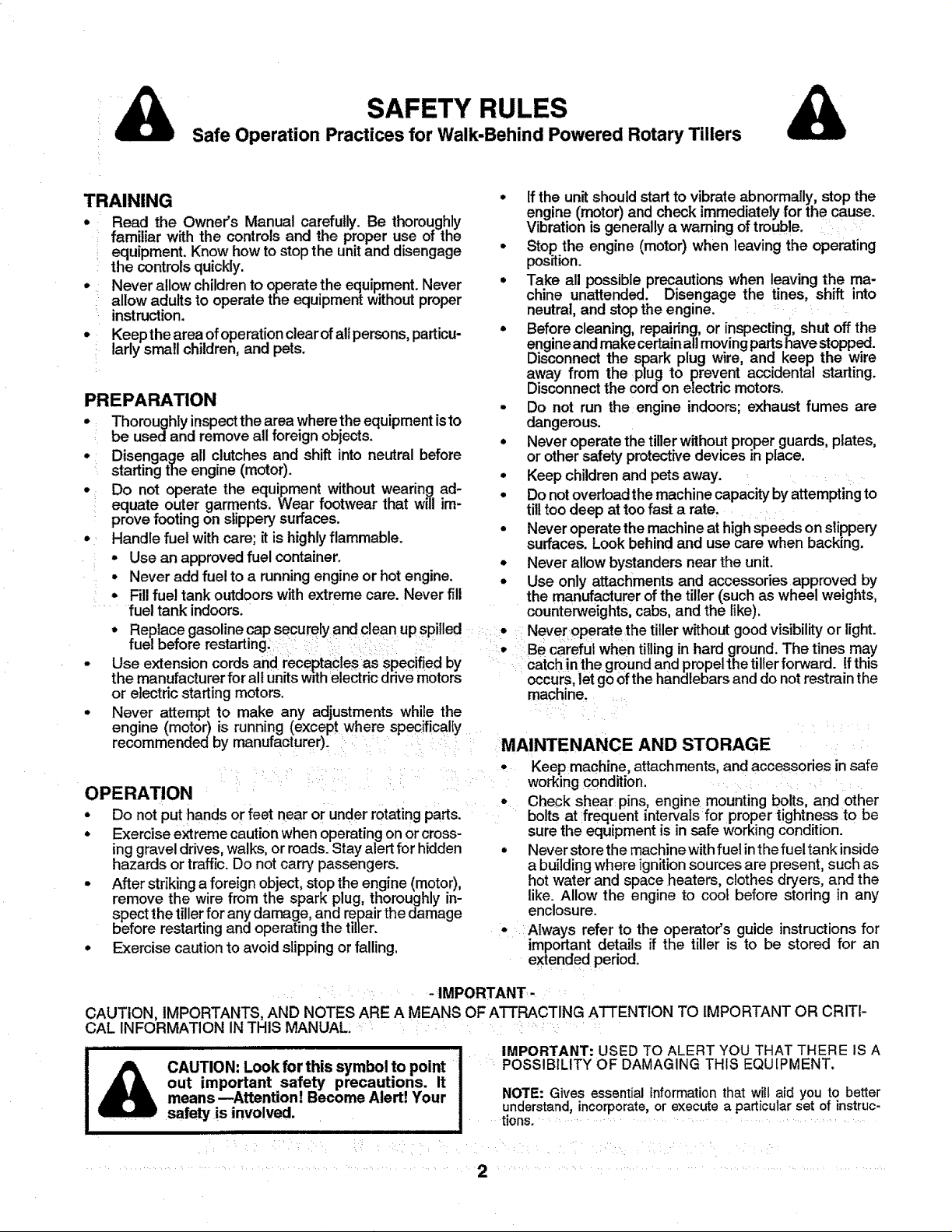
SAFETY RULES
Safe Operation Practices for Walk-Behind Powered Rotary Tillers
TRAINING
. Read the Owner's Manual carefully. Be thoroughly
familiar with the controls and the proper use of the
equipment. Know how to stop the unit and disengage
the controls quickly.
• Never allow children to operate the equipment. Never
allow adults to operate the equipment without proper
instruction.
• Keepthe area ofoperation clear of all persons, particu-
:: lady small children, and pets.
PREPARATION
• Thoroughlyinspectthearea where the equipment isto
be used and remove all foreignobjects.
• Disengage all clutches and shift into neutral before
starting the engine (motor).
• Do not operate the equipment without wearing ad-
equate outer garments. Wear footwear that will im-
prove footing on slippery surfaces.
• Handle fuel with care; it is highly flammable.
• Use an approved fuel container.
• Never add fuel to a running engine or hot engine.
• Fill fuel tank outdoors with extreme care. Never fill
fuel tank indoors.
° Replace gasoline cap securely and clean up spilled
fuel before restarting.
• Use extension cords and receptacles as specified by
the manufacturer for all units with electric drive motors
or electric starting motors.
• Never attempt to make any adjustments while the
engine (motor) is running (except where specifically
recommended by manufacturer).
OPERATION
, Do not put hands or feet near or under rotatingparts.
* Exercise extremecautionwhen operatingon orcross-
inggravel drives, walks, or roads.Stay alert for hidden
hazards or traffic. Do not carry passengers.
• After striking a foreign object,stop the engine (motor),
remove the wire from the spark plug, thoroughly in-
spect the tillerfor anydamage, and repairthe damage
before restartingand operatingthe tiller.
° Exercise cautionto avoid slipping or falling.
• If the unit should start to vibrate abnormally, stop the
engine (motor) and check immediately for the cause.
Vibration is generally a warning of trouble.
• Stop the engine (motor) when leaving the operating
position.
• Take all possible precautions when leaving the ma-
chine unattended. Disengage the tines, shift into
neutral, and stop the engine.
= Before cleaning, repairing, or inspecting, shut off the
engineand make certain all moving partshavestopped.
Disconnect the spark plug wire, and keep the wire
away from the plug to prevent accidental starting.
Disconnect the cord on electric motors,
• Do not run the engine indoors; exhaust fumes are
dangerous.
° Never operate the tiller without proper guards, plates,
or other safety protective devices in place.
° Keep children and pets away.
• Do not overload the machine capacity byattempting to
tilt too deep at too fast a rate.
= Never operate the machine at high speeds on slippery
surfaces. Look behind and use care when backing.
• Never allow bystanders near the unit.
• Use only attachments and accessories approved by
the manufacturer of the tiller (such as wheel weights,
counterweights, cabs, and the like).
• Never operate the tiller without good visibility or light.
• Be careful when tilling in hard ground. The tines may
catch in the ground and propel the tiller forward. If this
occurs, let go ofthe handlebars and do not restrain the
machine.
MAINTENANCE AND STORAGE
• Keep machine, attachments, and accessories insafe
wo_ing condition.
• Check shear pins, engine mounting bolts, and other
boltsat frequent intervals for proper tightness to be
sure the equipment isin safe workingcondition.
• Never store themachine withfuel inthe fueltank inside
a building where ignition sources are present, such as
hot water and space heaters, clothesdryers, and the
like. Allow the engine to cool before storing in any
enclosure.
• Always refer to the operator's guide instructionsfor
important details if the tiller is to be stored for an
extended period.
: : -IMPORTANT- :
CAUTION, IMPORTANTS, AND NOTES ARE A MEANS OF ATTRACTING ATTENTION TO IMPORTANT OR CRITI-
CAL INFORMATION IN THIS MANUAL: ........
IMPORTANT: USED TO ALERT YOU THAT THERE IS A
CAUTION: Look for this symbol to point
out important safety precautions. It
means--Attention! Become Alert! Your
.... safety is involved.
III
POSSIBILITY OF DAMAGING THiS EQU[PMENT.
NOTE: Gives essential information that will aid you to better
understand, incorporate, or execute a particular set of instruc-
tions. ................................................
CONGRATULATIONS onyour purchaseof a Sears Tiller.
It has been designed, engineered and manufacturedto
giveyou the best possible dependabilityand performance.
Should you experience any problems you cannot easily
remedy, please contact your nearest authorized Sears
Service Center/Department. They have competent,well-
trained technicians and the propertootstoserviceor repair
this unit. ....
Please read and retain this manual. The instructions will
enable you to assemble and maintain your tiller properly,
Always observe the "SAFETY RULES",
MODEL
NUMBER 917.299852
SERIAL
NUMBER
DATE OF
PURCHASE
THE MODEL AND SERIAL NUMBERS WILL BE
FOUND ON THE MODEL PLATE ATTACHED TO
THE TOP OF THE TRANSMISSION.
YOU SHOULD RECORD BOTH SERIAL NUMBER
AND DATE OF PURCHASE AND KEEP IN A SAFE
PLACE FOR FUTURE REFERENCE.
PRODUCT SPECIRCATIONS
HORSEPOWER,5.0,P
DISPLACEMENT: 12.57cu. in.
GASOLINECAPACITY: 3 Quarts :
UnleadedRegular
OIL: SAE 30W (Above32°F)
(CAPACITY:20oz.) SAE5W-30(Below32°F)
SPARKPLUG: Champion
(GAP: .030") RJ19LM
MAINTENANCE AGREEMENT
A SearsMaintenanceAgreement isavailable on thisprod-
uct. Contactyour nearest Sears store for details.
CUSTOMER RESPONSIBILITIES
• Read and observethe safety rules.
° Followaregularscheduleinmaintaining, caringfor and
usingyourtiller.
° Follow the instructions under the "Customer
Responsibilities"and "Storage" sections ofthisOwner's
Manual.
i i i II,H,H,,,HH,,,,III ,lUUlII III I I IIIII IIII
LIMITED TWO YEAR WARRANTY ON CRAFTSMAN TILLER
Fortwo yearsfrom date ofpurchase, when thisCraftsman Tiller is maintained,lubricated,and tuned up accordingto
the operating and maintenance instructions in the owner's manual, Sears will repair free of charge any defect in
materialor workmanship.
This Warranty does not cover:
• Expendable itemswhichbecome wornduring normal use,such as tines,spark plugs, air cleanersand belts.
• Repairs necessary because of operator abuse or negligence, includingbent crankshafts and the failure to
maintain the equipmentaccordingto the instructionscontainedinthe owner'smanual.
• If this Craftsman Tiller is usedfor commercialor rental purposes,this Warrantyapplies for only 30 days from the
date of purchase.
WARRANTY SERVICE tS AVAILABLE BY RETURNING THE CRAFTSMAN TILLER TO THE NEAREST SEARS
SERVICE CENTER/DEPARTMENT IN THE UNITED STATES. THIS WARRANTY APPLIES ONLY WHILE THiS
PRODUCT IS IN USEIN THE UNITED STATES.
This Warranty givesyouspecific legal rights,and you may also have otherrightswhichvaryfrom state to state.
SEARS, ROEBUCK AND CO., D/817 WA, HOFFMAN ESTATES, CHICAGO, ILLINOIS 60179
i
ilu ifll i i ill
- IMPORTANT-
This unitisequippedwithaninternalcombustionengine and shouldnotbe used onor near any unimprovedforest-covered,
brush-covered or grass covered land unless the engine's exhaust system is equipped with a spark arrester meeting
applicable local or state taws(if any). ifa spark attester is used, itshould be maintained in effective working order by the
operator. : i :
In the state of Californiathe above isrequired by law (Section4442 ofthe CaliforniaPublicResources Code). Other states
may have similarlaws. Federal lawsapplyon federal lands. See yourSears AuthorizedServiceCenter for sparkarrester.
Refer to the Repair Partssectionofthis manual for part number.
3
ill iiii ii iiii ii
LIiiiiiilll,ll,,l••;• • • ••• _ illii
TABLE OF CONTENTS
ill iiilll iiiill,,i i iii illl,llllll
SAFETY RULES ............................................................ 2
CUSTOMER RESPONSIBILITIES ...................... 3,13-15
PRODUCT SPECIFICATIONS ....................................... 3
WARRANT'/ ................................................................... 3
ACCESSORIES, ........................................................... 5
ASSEMBLY ................................................................ 6-8
MAINTENANCE SCHEDULE ...................................... 13
SERVICE & ADJUSTMENTS ................................. 15-18
STORAGE ..,................................................................. 19
TROUBLESHOOTING ;................................................ 20
REPAIR PARTS-TILLER ........................................ 21-26
REPAIR PARTS-ENGINE ....................................... 27-31
OPERATION .......................................................... ..9-12
INDEX
A Engine (cont'd)
Accessories ....................... ............... 5
Adjustments: Oil Type .............................. 11 14
Carburetor ............................... 18 Spark Plug ............................... 15
Depth Stake .............................. 10 Starting. ................................... 12
Handle Height ...:.........: ........:..:15 .... Stopping .i................................ 10
Side Shields ............................. 11 Storage :................................... 19
Throttle .................................... 18 Winter Operation ..................... 14
:Tines ................................... _:_...17 .....
V-Belt (Ground Drive) .............. 16 .....
Air Cleaner .......... _.................... 14 _ F
Belt: Type ......................................... 11
Belt Guard ............................... 16
Repair Parts ............................. 22
V-Be t (Ground Drive) .............. 16
Cooling System .............................. 14
Controls:
Choke ........................................ 9
Throttle ...................................... 9
Drive (Tines) .............................. 9
Cultivating. ..................................... 12
Customer Responsibilities:
Air Cleaner ............................... 14
Cooling System ....................... 14
Finish ....................................... 15
Maintenance Schedule ............ t3
Muffler .,..L.,..:..I:..._ ................. 15
Oil Change .......... :.................... 14
Spark Plug ............................... 15
TEnes........................................ 17
Transmission...; ....................... 15
V-Belt (Ground Drive) .............. 16
Depth Stake: Cultivatin_l ................................ 12 Troubleshooting .........:................... 20
Adjustment ............................... 10 Fill Fuel "l_'ank........................... 11
Repair Parts ............................. 25 Starting Engine _....................... 12 Transporting ................................... 11
: : _:_Stopping Tines & Engine ......... 10
• : E _ ..... Tilling ...:.,...:..: ......................... 10 i :: .... i: W :
En;'ine" Tilling Hints .............................. 12 Warranty ............ ""i ............... :....""..3
_-" "-' 14 Tine Operation ............. 10
AsrL;teaner................................. "........... 1 Wheels: :
Coolinn System 14 Transporting T,Iler.................... 1
FueIType ............,.,,... .......... ........ : i :ii: ..... : T"!'=,'",":"" ..... Repair Parts ............................. 23
" ....................... 11 : Winter Operation .... 14 Removal. ................................. 15
.... _ Lubrication _.............................. 14
..... Oil Level ................................... 11
Fuel: .....
B FillingTank .............................. 11
Storage .................................... 19
Finish: ^ .
- _ervlce"
Ma ntenance ............................ 15 - .
.......... _, ........ Sei_ice Record ........................ 13
:: _ : ..... Repair Parts ....................... 21-31
n
Handle:
Height Adjustment .................. 115
Repair Parts ............................. 21
L Gap ............................................ 3
Lubrication: Maintenance ............................ 15
Lubrication Chart .................... 13 Fuel System ............................. 19
Engine .................................. 14 Tiller._: ..................................... 19
M T
Muffler:
Maintenance 15 Tines: i
Spark Arrester ........................... 3 Arrangement/Replacement ......17
O
Oil:
Level ........................................ 11
D
Type .................................... t1,14
Operation:
Repair Parts:
Tiller .................................... 21-26
Engine ................................ 27-31
Rules for Safe Operation .................. 2
Service & Adjustments:
Carburetor ............................... 18
Handle Height .......................... 15
Side Shields ............................. 11
Throttle .................................... 18
Tines ........................................ 17
V-Belt (Ground Drive) .............. 16
Wheels ..................................... 15
Shear Pins:
Operation .................... i............ 12
Repair Parts ............................. 26
Spark Plug:
Storage:
Tilling ......................................... 10,12
Operation ................................. 10
Repair Parts ............................. 26
Shiraz:Pins ............................... 12
Transmission:
Maintenance ............................ 15
Repair Parts ............................. 24
R
:S
: i
4
A RIES
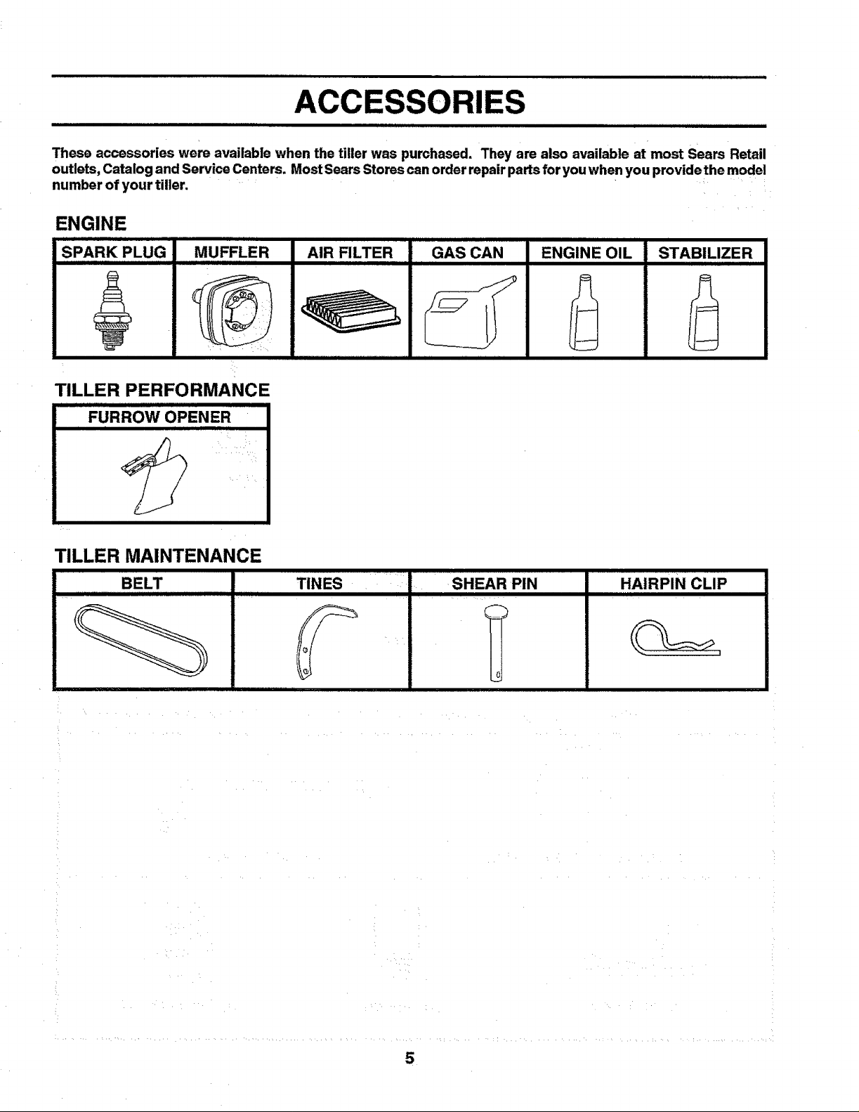
These accessories were available when the tiller was purchased. They are also available at most Sears Retail
outlets, Catalog and Service Centers. Most Sears Stores can order repair parts for you when you providethe model
number of your tiller.
ENGINE
SPARK PLUG MUFFLER AIR FILTER
TILLER PERFORMANCE
FURROW OPENER
TILLER MAINTENANCE
BELT
TINES iSHEAR PIN
IIIIII I
GAS CAN
ii iii
ENGINE OIL
IIIIIIIII IIIII
STABILIZER
HAIRPIN CLIP
_c
5
ASSEMBLY
(1) Utility knife
(1) Wire cutter
(1) Screwdriver
(1) Tire pressure gauge
(1) Pair of pliers
(1) 9/16" wrench (or 9/16" socket, ratchet, and exten-
sion;or adjustable wrench)
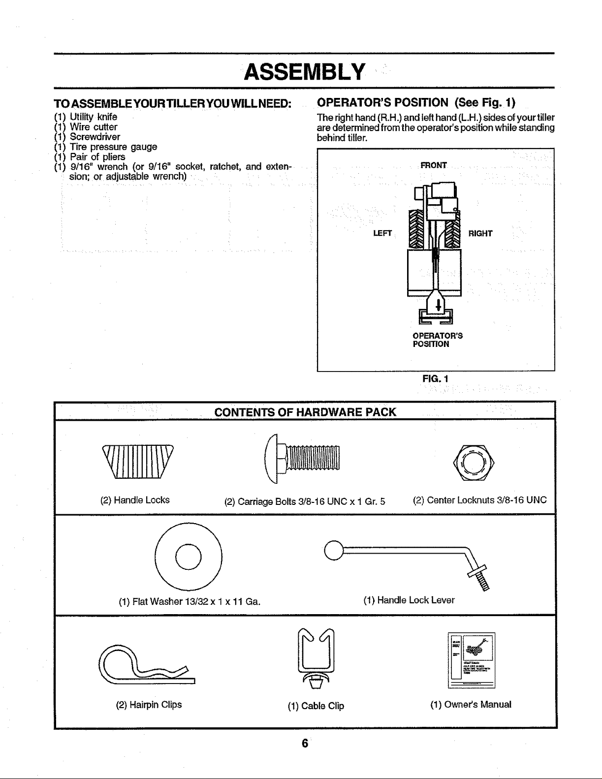
OPERATOR'S POSITION (See Fig, 1)
The righthand(R.H.) and left hand(L.H.) sides ofyourtiller
are determinedfromthe operator'spositionwhile standing
behind tiller.
FRONT
CONTENTS OF HARDWARE PACK
/IIIHIIIY
(2) Handle Locks
(2) Carriage Bolts 3/8-16 UNC x I Gr. 5 (2) Center Locknuts 3/8-16 UNC
i i r IIIIII
LEFT
RIGHT
OPERATOR'S
POSITION
FIG. 1
©
(1) Fiat Washer 13/32 x 1 x 11 Ga.
i
(1) Handle Lock Lever
U
(2) HairpinClips (1) Owners Manual
(1) Cable Clip
IIII IL II illl I I I I IIIII II I IIIIII
6:
ASSEMBLY
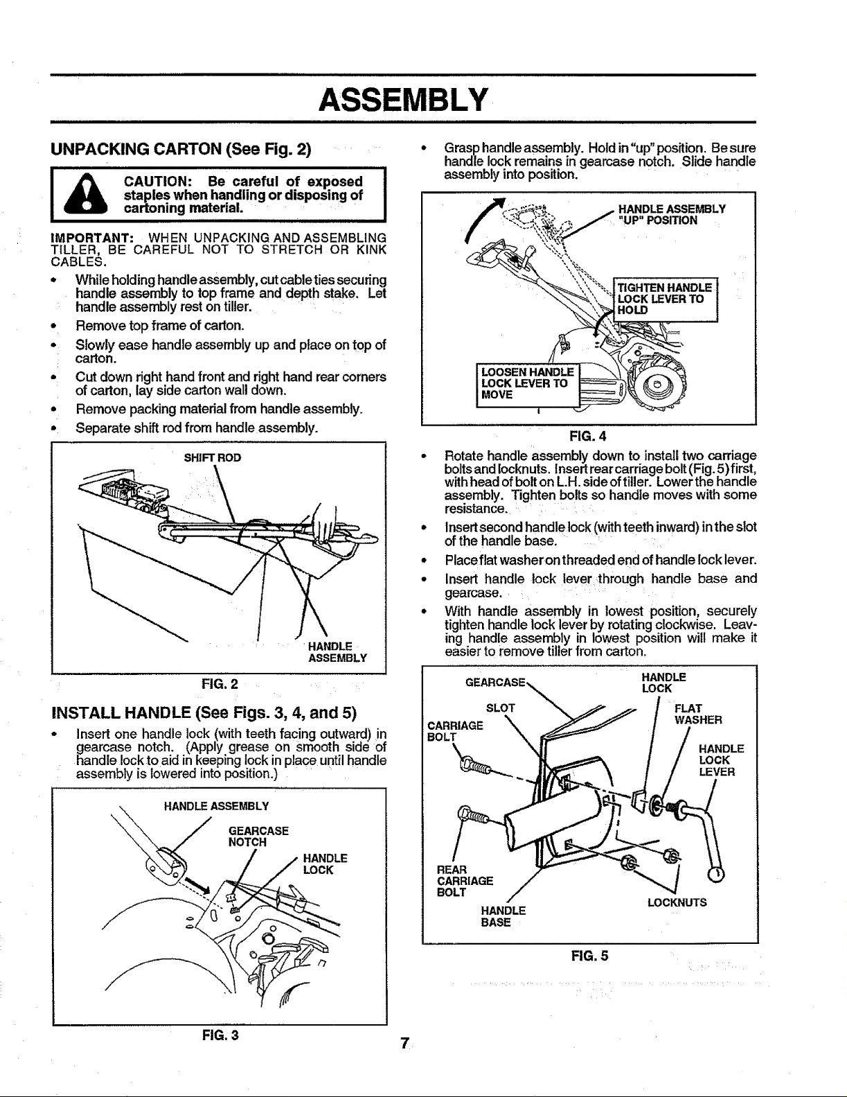
UNPACKING CARTON (See Fig. 2)
I_ CAUTION: Be careful of exposed
IMPORTANT: WHEN UNPACKING AND ASSEMBLING
TILLER, BE CAREFUL NOT TO STRETCH OR KINK
CABLES.
* While holding handle assembly, cut cableties securing
handle assembly to top frame and depth stake. Let
handle assembly rest on tiller.
Remove top frame of carton.
Slowly ease handle assembly up and place on top of
carton.
Cut down right handfront and righthand rear corners
of carton, lay side carton wall down.
Remove packing material from handle assembly.
Separate shift rod from handle assembly.
staples when handling or disposing of I
cartoning material.
SHIFT ROD
.... HANDLE
FIG. 2
ASSEMBLY
INSTALL HANDLE (See Figs. 3, 4, and 5)
- Insert one handle lock (with teeth facing outward)in
gearcase notch. (Apply grease on smooth side of
handle lock toaid in keeping lock in place untilhandle
assembly is lowered into position.)
Grasp handle assembly. Holdin "up" position. Be sure
handle lockremains in geamase notch. Slide handle
assembly into position.
I
HANDLE ASSEMBLY
"UP" POSITION
TIGHTEN HANDLE
LOCKLEVERTO
iHOLO
FIG. 4
• Rotate handle assembly down to install two carriage
boltsandIocknuts,Insert rear carriage bolt(Fig.5) first,
withhead ofbolton L.H.sideof tiller. Lowerthe handle
assembly. Tighten bolts so handle moves with some
resistance.
• Insertsecond handle]ock (with teethinward) in the slot
of the handle base.
° Placeflat washeron threaded end of handle Iocklever.
• Insert handle lock lever through handle base and
gearcase.
° With handle assembly in lowest position, securely
tighten handle lock lever by rotating clockwise. Leav-
ing handle assembly in lowest position will make it
easier to remove tiller from carton.
HANDLE
LOCK
SLOT FLAT
CARRIAGE WASHER
:BOLT
LOCK
HANDLE
LEVER
HANDLE ASSEMBLY
FIG, 3 7
REAR
CARRIAGE
BOLT
HANDLE
BASE
LOCKNUTS
FIG. 5
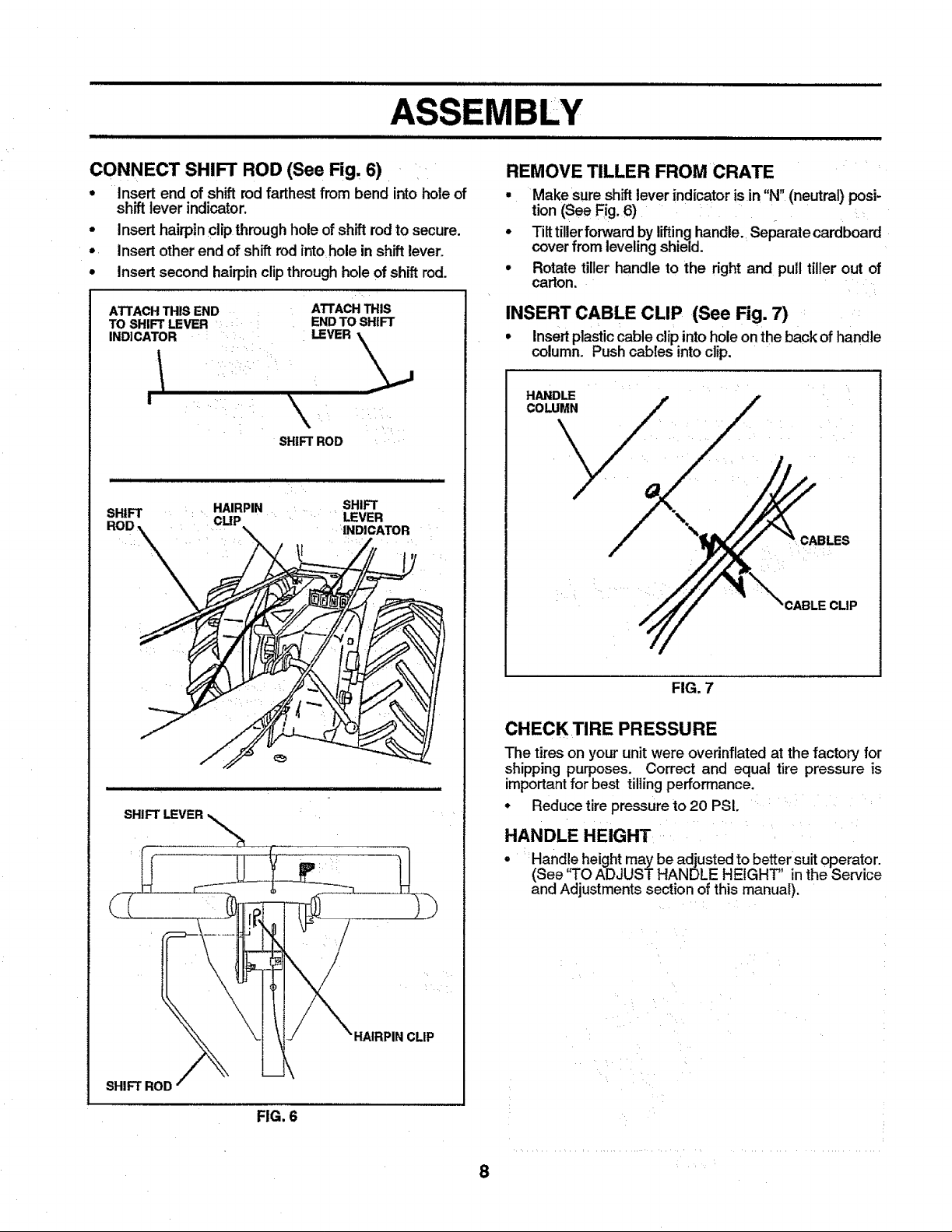
CONNECT SHIFT ROD (See Fig. 6)
. Insert end of shift rod farthest from bend into hole of
shift lever indicator,
• Insert hairpinclip through hole of shift rod to secure.
° insert otherend of shift rod into hole in shift lever.
° Insert second hairpinclipthroughholeof shift rod.
ATTACHTHISEND
TO SHIFT LEVER :
INDICATOR
I
illliH ii j ii ii llll i ii ...............
ATTACH THIS
END TO SHIFT
LEVER .\_,_
SHIFT ROD
REMOVE TILLER FROM CRATE
g
Make sure shift lever indicator isin "N" (neutral) posi-
tion (See Fig. 6)
Tilt tiller forward by lifting handle. Separate cardboard
cover from leveling shield.
Rotate tiller handle to the right and pull tiller out of
carton.
INSERT CABLE CLIP (See Fig. 7)
• Insert plastic cable clip intohole on the back of handle
column. Pushcables into clip.
SHIFT : _ HAIRPIN SHIFT
SHIFT LEVER
CLIP _ LEVER
INDICATOR
CABLECLIP
FIG. 7
CHECK TIRE PRESSURE
The tires on your unit were overinflated at the factory for
shipping purposes. Correct and equal tire pressure is
important for best tilling performance.
• Reduce tire pressure to 20 PSI.
HANDLE HEIGHT
• Hand!e height may be adjusted to better suit operator.
(See q'O ADJUST HANDLE HEIGHT' inthe Service
and Adjustments section of this manual).
SHIFT ROD
HAIRPINCLIP
FIG. 6
8

KNOW YOUR TILLER
READ THIS OWNER'S MANUAL AND SAFETY RULES BEFORE OPERATING YOUR TILLER.
Compare the illustrationswithyour til!ertofamiliarize yourselfwiththe location of various controlsand adjustments. Save
this manual for future reference. ......
DRIVE THROTTLE
BAR
DEPTH STAKE
LEVELING
SHIELD
OUTER
SIDE
SHIELD
CONTROL
r LEVER
SHIFT LEVER
INDICATOR
CHOKE CONTROL
RECOIL
STARTER
HANDLE
MEETS ANSI SAFETY REQUIREMENTS
Our tillers conform to the safety standards of the American National Standards Institute.
DRIVE CONTROL BAR - Used to engage tines.
DEPTH STAKE- Controls depth at whichtillerwilldig.
LEVELING SHIELD - Levelstilled soil.
OUTER SIDE SHIELD - Adjustable tOprotectsmall plants
from being buried.
THROTTLE CONTROL - Used to controlengine speed.
SAFETY DECAL
The decal shown below is located on the handle of your tiller.
FIG. 8
SHIFT LEVER - Used to shift transmission gears.
SHIFT LEVER INDICATOR - Shows which gear the
transmission is in.
RECOIL STARTER HANDLE - Used to start the engine.
CHOKE CONTROL - Used when starting a cold engine.
q I qlm Ill IIIIIJl I J IIIlllJ/JJ_lJ/gll/;ll JJJII II/IIqlIIIIHJHIH I I II III IIIIIIIIIII III II II
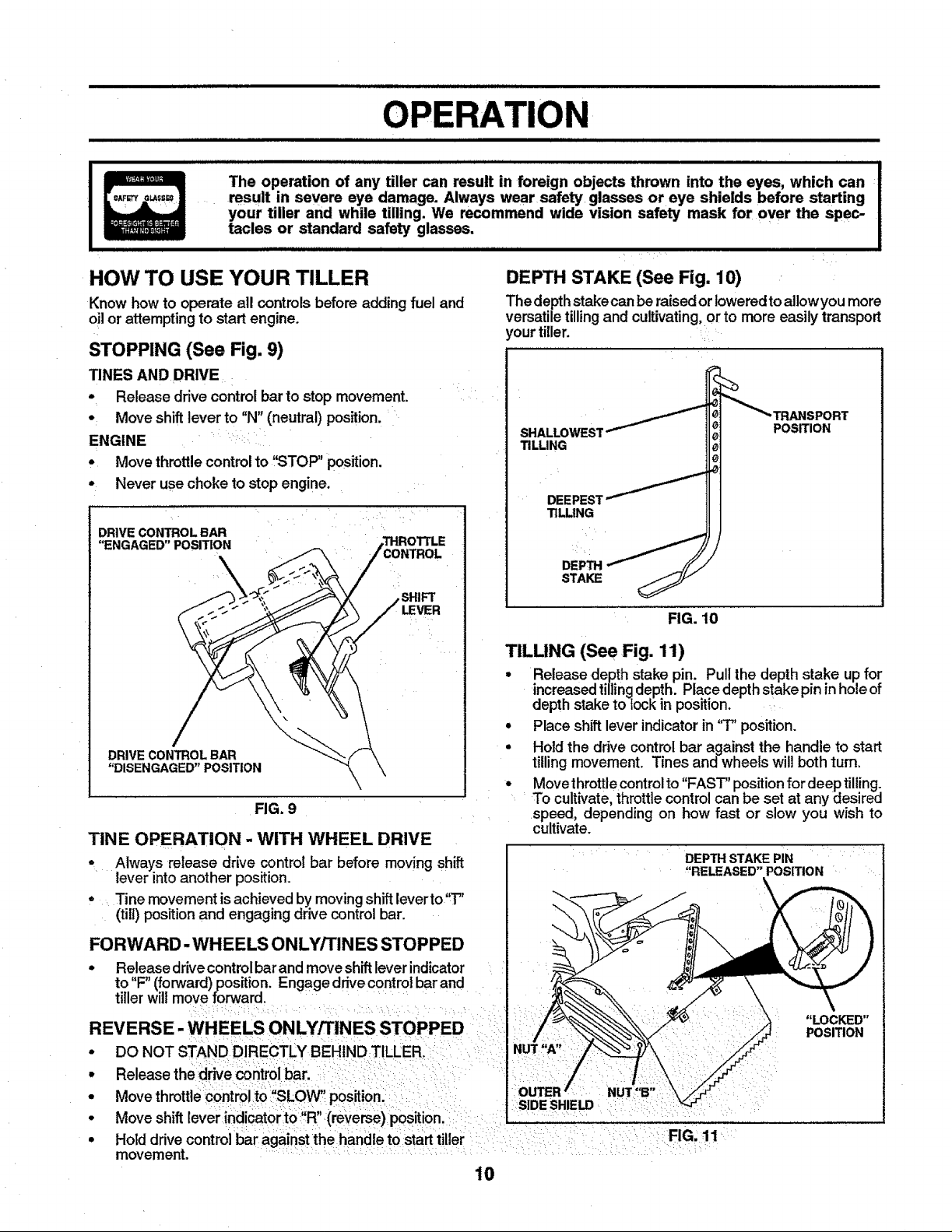
OPERATION
The operation of any tiller can result in foreign objects thrown into the eyes, which can
result in severe eye damage. Always wear safety glasses or eye shields before starting
your tiller and while tilling. We recommend wide vision safety mask for over the spec-
tacles or standard safety glasses.
i iiiii iiiiiiiiiii iii
HOW TO USE YOUR TILLER
Know how to operate all controlsbefore adding fuel and
oil or attemptingto start engine.
STOPPING (See Fig. 9)
TINES AND DRIVE
• Release drive control bar to stop movement.
• Move shiftlever to "N" (neutral) position.
ENGINE _ :
• Move throttlecontrolto "STOP" position.
• Never use choke to stop engine.
DRIVE CONTROL BAR
"ENGAGED" POSITION
,SHIFT
LEVER
DRIVECONTROLBAR
"DISENGAGED" POSITION
FIG. 9
TINE OPERATION - WITH WHEEL DRIVE
* Always release drive control bar before moving shift
lever into another position.
• Tine movement is achieved by moving shift leverto"T"
(till) position and engaging drive controlbar.
DEPTH STAKE (See Fig. 10)
The depthstakecan be raisedorloweredtoallowyou more
versatiletillingand cultivating,or to more easily transport
,ourtiller.
SHALLOWES1
TILLING
TILLING
POSITION
FIG. 10
TILLING (See Fig. 11)
• Release depth stake pin. Pull the depth stake up for
increased tilling depth. Place depth stake pin in hole of
depth stake to lock in position.
• Place shift lever indicator in '3" position.
• Hold the drive control bar against the handle to start
tilling movement. Tines and wheels wil! both turn.
• Move throtttecontrol to "FAST" position for deep tilling.
To cultivate, throttle control can be set at any desired
speed, depending on how fast or slow you wish to
cultivate.
DEPTHSTAKEPIN
"RELEASED"POSITION
\
FORWARD-WHEELS ONLY/TINES STOPPED
• Release drivecontrol bar and move shift lever indicator
to"F" (forward) position. Engage drive control barand
tiller will move forward.
REVERSE- WHEELS ONLY/TINES STOPPED
• DO NOT STAND DIRECTLY BEHIND TILLER.
• Release thedrive controlbar.
• Move throttlecontrolto "SLOW' position.
• Move shift lever indicatorto:,R" (reverse) position.
• Hold drivecontrolbar against the handle to starttiller
movement.
"LOCKED"
POSITION
NUT "A"
NUT"B"
SIDE SHIELD
FIG, 11
10
 Loading...