

Craftsman 917299642 Owner’s Manual
SWAURS
OWNER'S
MANUAL
MODEL NO,
917.299642
Caution:
Read and follow
all Safety Rules
and Instructions
Before Operating
This Equipment
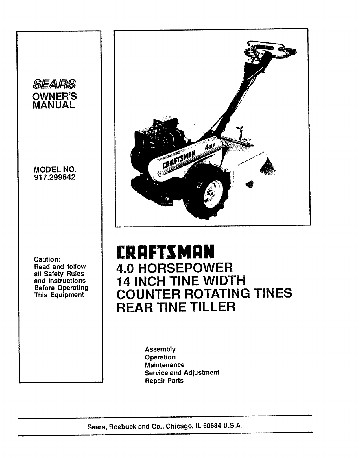
£RI:IFTSMI:IN
4.0 HORSEPOWER
14 INCH TINE WIDTH
COUNTER ROTATING TINES
REAR TINE TILLER
Assembly
Operation
Maintenance
Service and Adjustment
Repair Parts
Sears, Roebuck and Co., Chicago, IL 60684 U.S.A.
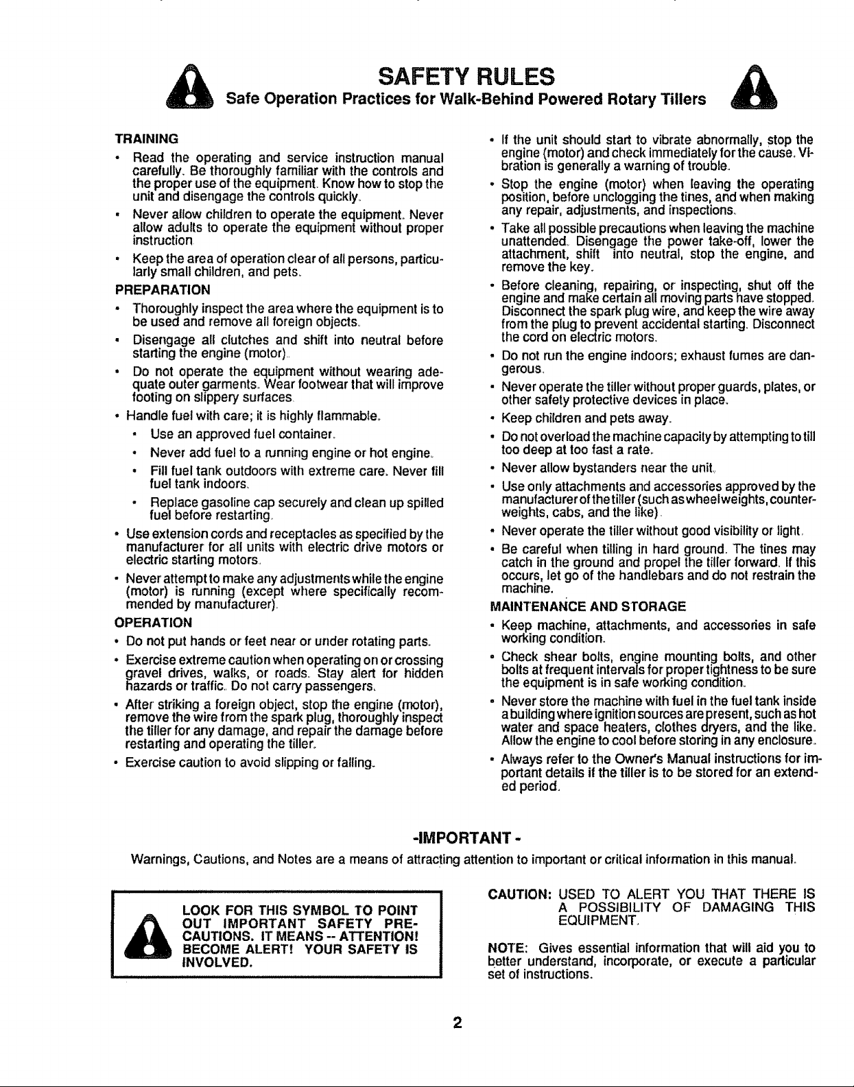
Safe Operation Practices for Walk-Behind Powered Rotary Tillers
SAFETY RULES
&
TRAINING
- Read the operating and service instructionmanual
carefully. Be thoroughlyfamiliar with the controls and
the proper use of the equipmentv Know howto stopthe
unit and disengage the controls quickly_
• Never allow children to operate the equipment° Never
allow adults to operate the equipment without proper
instruction
. Keep the area of operation clear of allpersons, particu-
larly small children, and pets_
PREPARATION
° Thoroughly inspectthe area where the equipment isto
be used and remove all foreign objects°
. Disengage all clutches and shift into neutral before
starting the engine (motor)..
= Do not operate the equipment without wearing ade-
quate outer garments.. Wear footwear that will improve
footing on slippery"surfaces.
. Handle fuel with care; it is highly flammable..
• Use an approved fuel container.,
• Never add fuel to a running engine or hot engine.
• Fillfuel tank outdoors with extreme care. Never fill
fuel tank indoors_
• Replace gasoline cap securely and clean upspilled
fuel before restarting
• Use extension cords andreceptaclesasspecified bythe
manufacturer for all units with electric drive motors or
electric starting motors.
• Never attempt to make any adjustments while the engine
(motor) is running (except where specifically recom-
mended by manufacturer),
OPERATION
. Do not put hands or feet near or under rotating parts.,
° Exercise extreme caution when operating on orcrossing
gravel drives, walks, or roads_ Stay alert for hidden
hazards or traffic, Do not carry passengers,
• After' striking a foreign object, stop the engine (motor),
remove the wire from the spark plug, thoroughly inspect
the tiller for any damage, and repair the damage before
restarting and operating the tillers.
• Exercise caution to avoid slipping or falling.
. If the unit should start to vibrate abnormally, stop the
engine (motor) and check immediately forthe cause°Vi-
bration is generally awarning of trouble.,
. Stop the engine (motor) when leaving the operating
position, before unclogging the tines, and when making
any repair, adjustments, and inspections,
° Take all possible precaufionswhen leaving the machine
unattended., Disengage the power take-off, lower the
attachment, shift into neutral, stop the engine, and
remove the key.
• Before cleaning, repairing, or' inspecting, shut off the
engine and make certain all moving parts have stopped_
Disconnect the spark plug wire, and keep the wire away
from the plug to prevent accidental starting Disconnect
the cord on electric motors.
° Do not run the engine indoors;exhaust fumesare dan-
gerous.
• Never operate the tillerwithout properguards, plates, or
other safety protective devices in place.
• Keep children and pets away.
• Donotoverload the machine capacity by attempting totill
too deep at too fast a rate.
• Never allow bystanders near the unit.,
• Use only attachments and accessories approved by the
manufacturer ofthetirler(such aswheelweights, counter_
weights, cabs, and the like).
• Never operate the tillerwithout good visibility or light,
• Be careful when tilling in hard ground. The tines may
catch in the ground and propel the tiller forward. Ifthis
occurs, let go of the handlebars and do not restrainthe
machine.
MAINTENANCE AND STORAGE
• Keep machine, attachments, and accessories in safe
workingcondition..
. Check shear bolts, engine mounting bolts, and other
bolts at frequent intervalsfor propertightnessto be sure
the equipmentisin safe workingcondition_
. Never storethe machine withfuel inthe fuel tankinside
abuildingwhere ignitionsourcesare present,suchas hot
water and space heaters, clothesdryers, and the like.
Allowthe enginetocoolbeforestoringinany enclosure.,
. Always refer to the Owner's Manual instructionsfor im-
portantdetails ifthe tiller isto be storedfor an extend-
ed period.
-IMPORTANT -
Warnings, Cautions, and Notes are a means of attracting attentionto importantor criticalinformationinthis manual.,
illll i ill i i illl illlllllllllllllll illlll
LOOK FOR THIS SYMBOL TO POINT
OUT IMPORTANT SAFETY PRE-
CAUTIONS. IT MEANS -- ATTENTION!
BECOME ALERT! YOUR SAFETY IS
INVOLVED.
CAUTION: USED TO ALERT YOU THAT THERE IS
A POSSIBILITY OF DAMAGING THIS
EQUIPMENT_
NOTE: Gives essential informationthat will aid you to
better understand, incorporate, or execute a particular
set of instructions.
2
CONGRATULATIONS on your purchase of a Sears
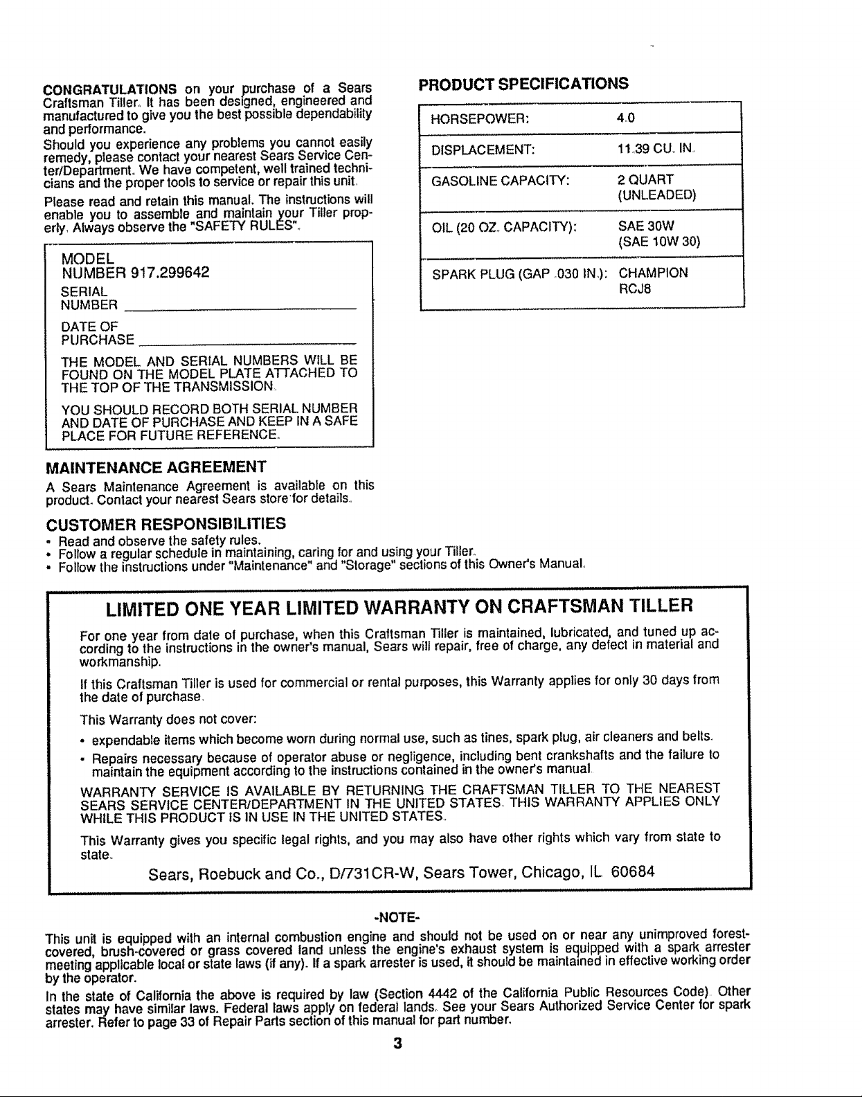
PRODUCT SPECIFICATIONS
Craftsman Tiller° it has been des=gned,engineered and
manufacturedto give you the bestpossibledependability
and performance.
Should you experience any problems you cannoteasily
remedy, please contactyournearest Sears Service Cen-
HORSEPOWER: 4_0
DISPLACEMENT: 11,39 CUoIN,,
teriDepartmentoWe have competent,well trainedtechni-
cians and the propertools to service or repairthisunit
GASOLINE CAPACITY: 2 QUART
Please read and retain this manual. The instructionswill
enable you to assembleand maintainyour Tiller prop-
erty, Always observe the SAFETY RULES
OIL (20 OZ. CAPACITY): SAE 30W
MODEL
NUMBER 917.299642
SPARK PLUG (GAP ,030 IN,): CHAMPION
SERIAL
NUMBER
DATE OF
PURCHASE
THE MODEL AND SERIAL NUMBERS WILL BE
FOUND ON THE MODEL PLATE ATTACHED TO
THE TOP OF THE TRANSMISSION,
YOU SHOULD RECORD BOTH SERIAL NUMBER
AND DATE OF PURCHASE AND KEEP IN A SAFE
PLACE FOR FUTURE REFERENCE,,
MAINTENANCE AGREEMENT
A Sears Maintenance Agreement is available on this
product. Contact your nearest Sears store'for details,
CUSTOMER RESPONSIBILITIES
. Read and observe the safety rules.
• Follow a regular schedule in maintaining, caring for and using your Tiller_
. Fo_towthe instructionsunder Maintenance" and "Storage" sections of thisOwner's Manual,,
(UNLEADED)
(SAE 10W 30)
RCJ8
LIMITED ONE YEAR LIMITED WARRANTY ON CRAFTSMAN TILLER
For one year from date of purchase, when this Craftsman Tiller is maintained, lubricated, and tuned up ac-
cording to the instructions in the owner s manual, Sears wilt repair, free of charge, any detect in material and
workmanship,,
If this Craftsman Tiller is used for commercial or rental purposes, this Warranty applies for only 30 days from
the date of purchase.
This Warranty does not cover:
• expendable itemswhich become worn during normal use, such as tines, spark plug, air cleaners and bells,
• Repairs necessary because of operator abuse or negligence, including bent crankshafts and the failure to
maintain the equipment according to the instructions contained in the owner's manual
WARRANTY SERVICE IS AVAILABLE BY RETURNING THE CRAFTSMAN TILLER TO THE NEAREST
SEARS SERVICE CENTER/DEPARTMENT IN THE UNITED STATES. THIS WARRANTY APPLIES ONLY
WHILE THIS PRODUCT iS IN USE IN THE UNITED STATES
This Warranty gives you specific legal rights, and you may also have other rights which vary from state to
state.,
Sears, Roebuck and Co., D/731CR-W, Sears Tower, Chicago, IL 60684
-NOTE-
This unit is equipped with an internalcombustion engine and should not be used on or near any unimprovedforest-
covered, brush-covered or grass covered land unless the engine's exhaust system is equipped with a spark arrester
meetingapplicablelocal or statelaws(if any). Ifa sparkarrester is used, it should be maintained in effectiveworkingorder
by the operator.
in the state of California the above is required by law (Section 4442 of the California Public Resources Code) Other
states may have similar laws. Federal laws apply on federal lands, See your Sears Authorized Service Center for spark
arrester. Refer to page 33 of Repair Partssection of this manualfor part number.
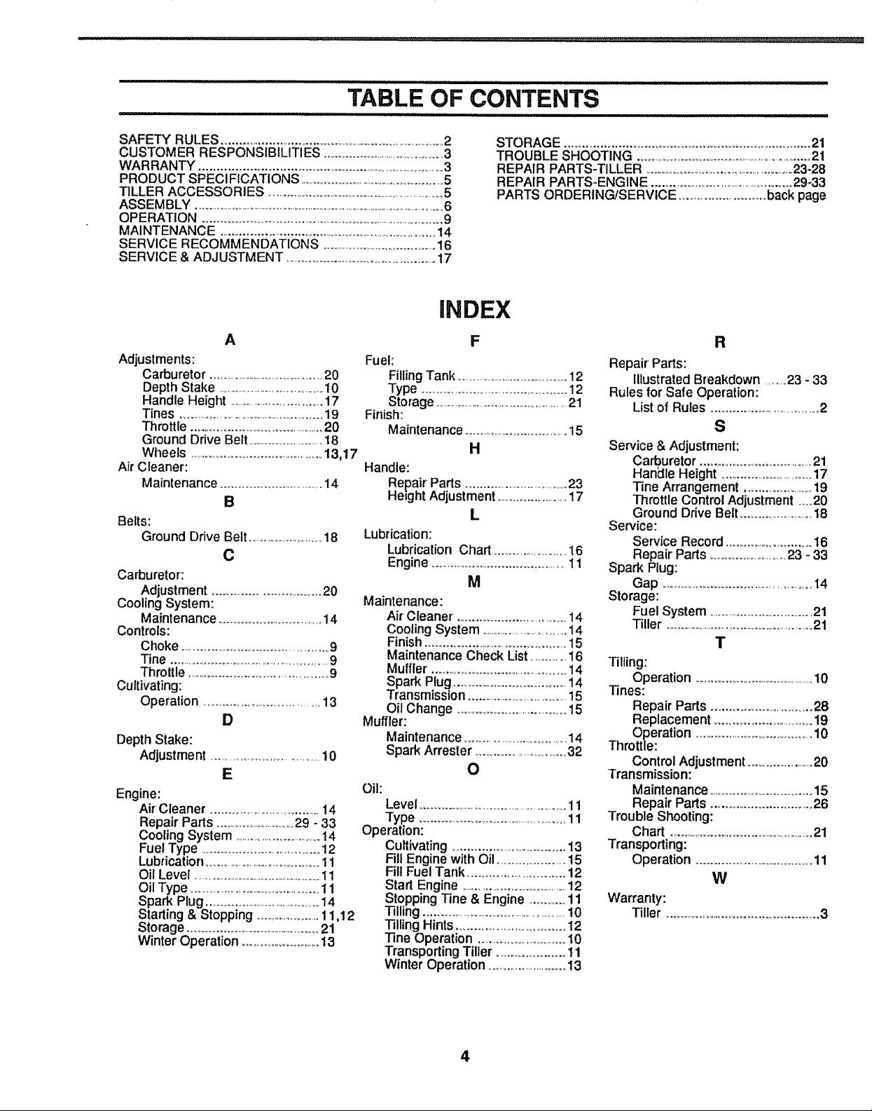
TABLE OF CONTENTS
, iii1,,Jl,Jll,,,Jlll,,Ji J, i, ,,ulJl, i,ii,llll,ll,,ii,u,lll iin iii i i ii i i i
SAFETY RULES ............................................................................ 2
CUSTOMER RESPONSIBILITIES ...............................................3
WARRANTY ...............................................................................3
PRODUCT SPECI FICATtONS ..................................................5
TILLER ACCESSORIES ........................................................................5
ASSEMBLY ...................................................................................................................6
OPERATION ............................................................................................9
MAINTENANCE .............................................................................14
SERVICE RECOMMENDATIONS ...........................................16
SERVICE & ADJUSTMENT ..............................................................17
A
Adjustments:
Carburetor ......................................................20
Depth Stake ...............................................10
Handle Height .....................................17
Tines .........................................................19
Throttle ...............................................20
Ground Drive Belt ................................18
Wheels ....................................................13,17
Air Cleaner:
Maintenance ......................................14
B
Belts:
Ground Drive Belt .................................18
C
Carburetor':
Adjustment ......................................20
Cooling System:
Maintenance.........................................14
Controls:
Choke ..................................................9
Tine .................................................................9
Throttle ..............................................9
Cultivating:
Operation ....................................13
D
Depth Stake:
Adjustme nt ..........................................10
Fuel:
Filling Tank ..................................................12
Type ................................................12
Storage ...........................................................21
Finish:
Maintenance ...........................................15
Handle:
Repair Parts .....................................23
Height Adjustment ........................17
Lubrication:
Lubrication Chart ..............................16
Engine .................................................11
Maintenance:
Air Cleaner. ...............................14
Cooling System ......................................14
Finish ................................................15
Maintenance Check List...............i6
Muffler ...................................................14
Spark Plug..........................................14
Transmission .................................15
Oil Change ..........................................15
Muffler:
Maintenance.....................................14
Spark Arrester ...............................32
E
Engine:
Air'Cleaner .....................................14
Repair Parts ..................................29 - 33
Cooling System .....................................14
Fuel Type ...........................................12
Lubrication.........................................11
Oil Level .........................................................11
Oil Type ..................................................11
Spark Plug ...............................................14
Starting & Stopping ..........................11,t2
Storage .................................................21
Winter Operation ................................13
Oil:
Level .........................................................11
Type .....................................................11
Operation:
Cultivating.....................................13
Fill Engine with Oil ......................15
Fill Fuel Tank ..............................12
Start Engine ....................................12
Stopping Tine & Engine ..............11
Tilling .....................................................10
Tilling Hints ..................................t2
Tine Operation ...................................10
Transporting Tiller ......................11
Winter Operation ..............................13
INDEX
F
H
L
M
O
STORAGE .................................................................... 21
TROUBLE SHOOTING .......................................................................21
REPAIR PARTS-TILLER ...........................................................23-28
REPAIR PARTS-ENGINE .......................................................29-33
PARTS ORDERING/SERViCE ................................back page
R
Repair Parts:
Illustrated Breakdown ........23 - 33
Rules for Safe Operation:
List of Rules .....................................2
S
Service & Adjustment:
Carburetor .......................................21
Han_lle Height ................................17
Tine Arrangement ..........................19
Throttle Control Adjustment ....20
Ground Drive Belt ............................I8
Service:
Service Record ...................................16
Repair Parts...........................23 - 33
Spark Plug:
Gap ........................................................t4
Storage:
Fuel System ...................................21
Tiller ........................................................21
T
Tilling:
Operation ....................................................10
Tines:
Repair Parts .................................28
Replacement ..................................19
Operation ...............................................10
Throttle:
Control Adjustment .....................20
Transmission:
Maintenance ..................................15
Repair Parts .................................26
Trouble Shooting:
Chart ..................................................21
Transporting:
Operation .........................................11
W
Warranty:
Tiller .......................................................3
4

TILLER ACCESSORIES
THESE ACCESSORIES WERE AVAILABLE WHEN THE TILLER WAS PURCHASED. THEY ARE ALSO AVAILABLE AT
MOST SEARS RETAIL OUTLETS, CATALOG AND SERVICE CENTERS. MOST SEARS STORES CAN ORDER REPAIR
PARTS FOR YOU, WHEN YOU PROVIDE THE MODEL NUMBER OF YOUR TILLER,
ENGINE
SPARK PLUG
MUFFLER
AIR FILTER GAS CAN
ENGINE OIL
STABILIZER
ill, lll,ii
TILLER PERFORMANCE
FURROW OPENER
TILLER MAINTENANCE
BELT TINES RETAINING PIN HAIRPIN CLIP
...................... , i............ ,i ....
%
,2
................. iii iljlllll I I II IIIIII1[
5
ASSEMBLY
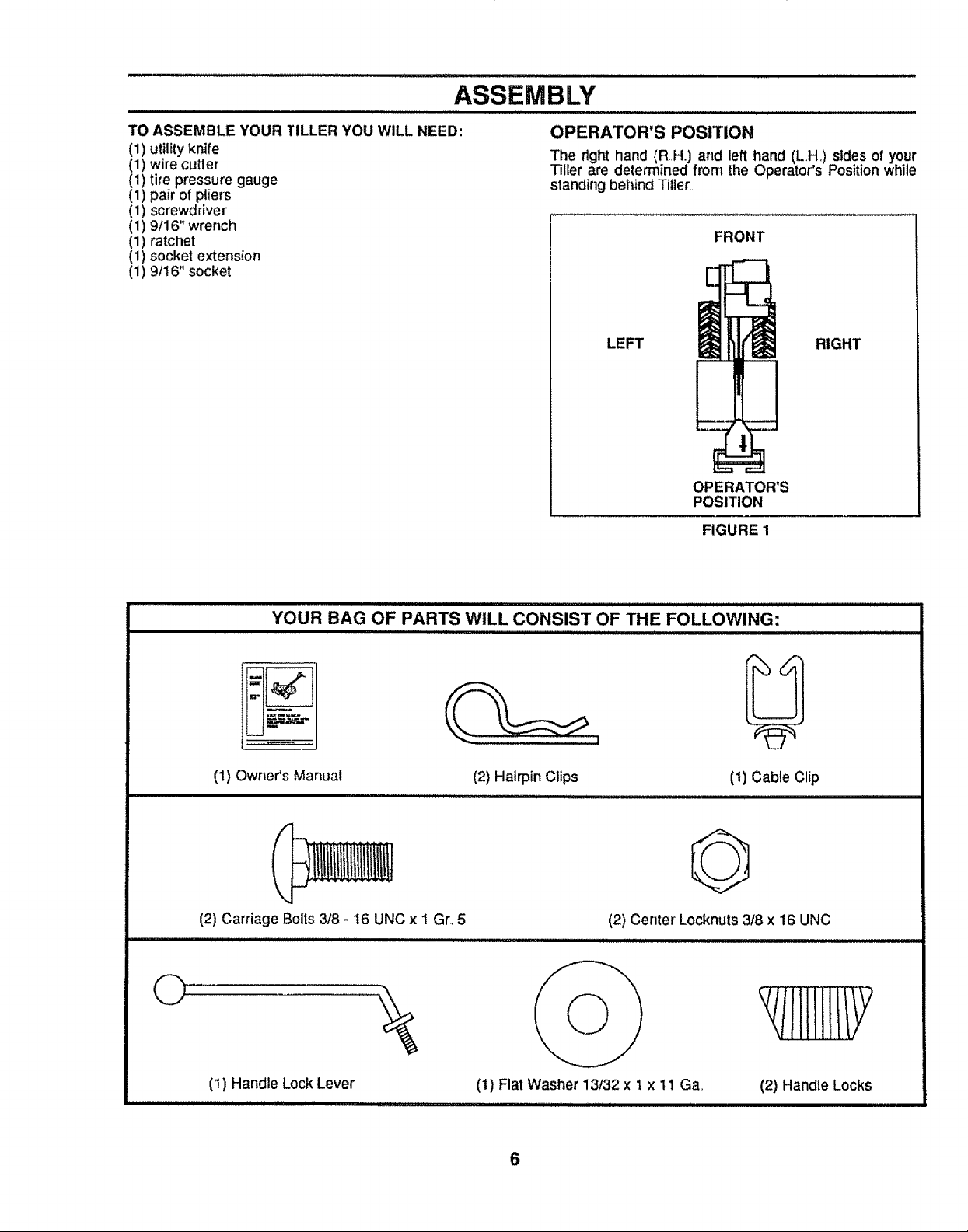
TO ASSEMBLE YOUR TILLER YOU WILL NEED:
(1) utility knife
(1) wire cutter
(1) tire pressure gauge
(1) pair of pliers
(1) screwdriver
(1) 9/16" wrench
(1) ratchet
(1) socket extension
(1) 9/16" socket
OPERATOR'S POSITION
The right hand (RH.) and left hand (LH,) sides of your
Tiller are determined from the Operator's Position while
standing beilind Tiller
FRONT
LEFT RIGHT
OPERATOR'S
POSITION
FIGURE 1
O
YOUR BAG OF PARTS WILL CONSIST OF THE FOLLOWING:
(1) Owner's Manual
IIIIIIIIIIIlUlIIIIIIIIIIIIIlUlUlIII I I III1'11'11'111111 I I I .....
(2) Carriage Bolts 3/8 - 16 UNC x 1 Gr..5
(2) Hairpin Clips (1) Cable Clip
O
(2) Center Locknuts 3/8 x 16 UNC
(1) Handle Lock Lever
iiiiiiii ilUl,ll,ll_UUll,i-iiiuiiii iiiii
(1) Fiat Washer 13/32 x 1 x 11 Ga.
iiiiiiiiiiiiii ii I iiiii I i i
6
(2) Handle Locks
ASSEMBLY
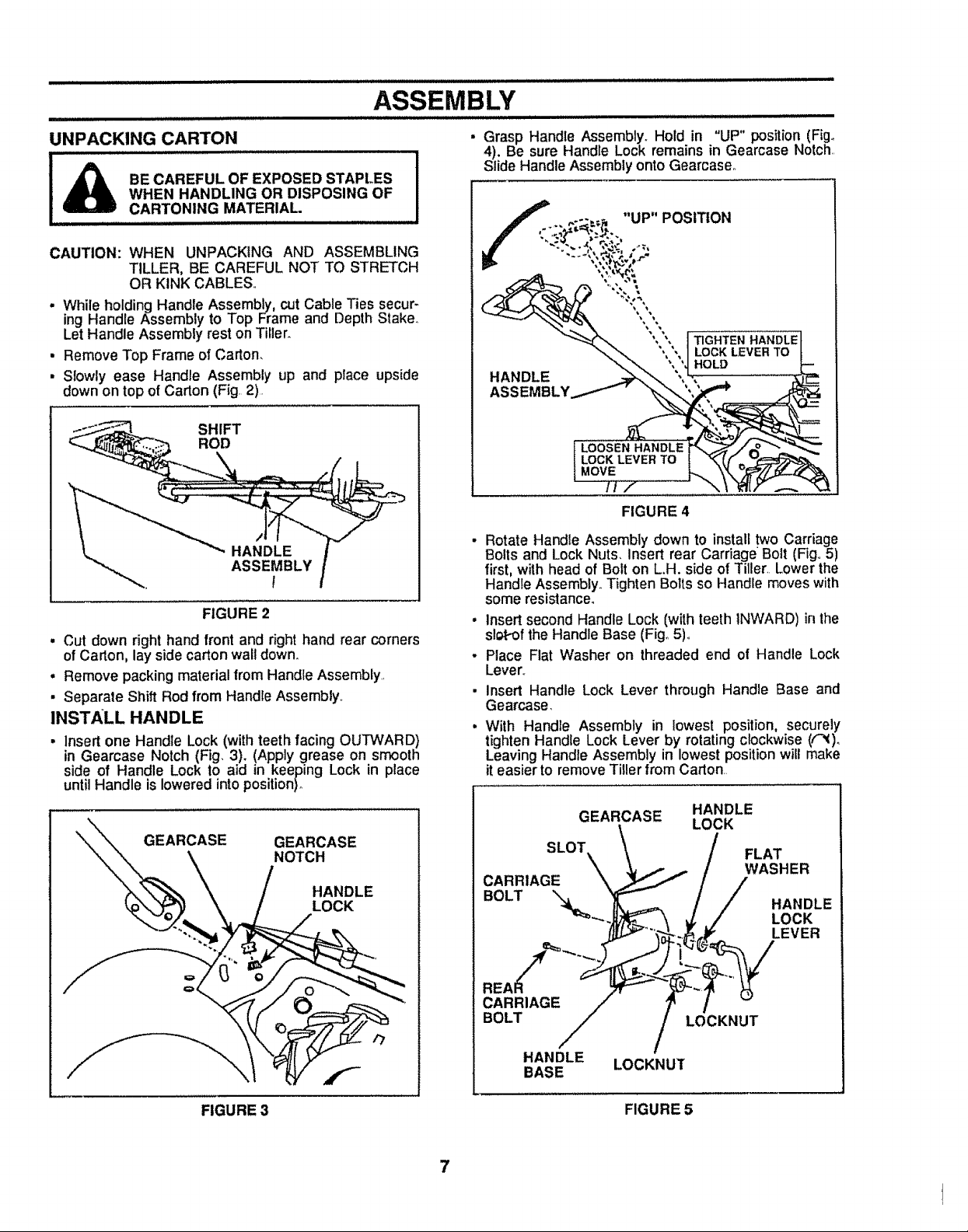
UNPACKING CARTON
WHEN HANDLING OR DISPOSING OF
BE CAREFUL OF EXPOSED STAPLES
CARTONING MATERIAL.
.... H,H,
CAUTION: WHEN UNPACKING AND ASSEMBLING
TILLER, BE CAREFUL NOT TO STRETCH
OR KINK CABLES,,
. While holding Handle Assembly, cut Cable Ties secur-
ing Handle Assembly to Top Frame and Depth Slake°
Let Handle Assembly rest on Tiller.
• Remove Top Frame of Carton.
• Slowly ease Handle Assembly up and place upside
down on top ofCarton (Fig. 2).
FIGURE 2
• Cut down right hand front and right hand rear corners
of Carton, lay side carton wall down.,
• Remove packing material from Handle Assembly,,
• Separate Shift Rod from Handle Assembly,
INSTALL HANDLE
• Insertone Handle Lock (with teeth facing OUTWARD)
in Gearcase Notch (Fig. 3). (Apply grease on smooth
side of Handle Lock to aid in keeping Lock in place
until Handle is lowered into position)°
Grasp Handle Assembly. Hold in "UP" position (Fig.
4), Be sure Handle Lock remains in Gearcase Notch,,
Slide Handle Assembly onto Gearcaseo
f ,...-..= "UP" POSITION
"": "" ', ', _GF'_'_EN HANDLE
"_._ "',", I LOCK LEVER TO
HANDLE ==,_'_. ', -, ....
• Rotate Handle Assembly down to install two Carriage
Bolts and Lock Nuts, Insert rear Carriage Bolt (Fig,,5)
first, with head of Bolt on L.H. side of Tiller, Lower the
Handle Assembly,,Tighten Bolts so Handle moves with
some resistance.
• Insert second Handle Lock (with teeth INWARD) inthe
slot-of the Handle Base (Fig,,5)°
- Place Flat Washer on threaded end of Handle Lock
Lever.,
• Insert Handle Lock Lever through Handle Base and
Gearcase.
• With Handle Assembly in lowest position, securely
tighten Handle Lock Lever by rotating clockwise ((_)o
Leaving Handle Assembly in lowest position wilt make
it easier to remove Tiller from Carton,
_?'_ " "t HOLD
z
FIGURE 4
GEARCASE GEARCASE
NOTCH
HANDLE
LOCK
FIGURE 3
GEARCASE HANDLE
\
SLOT \ / FLAT
LOCK
c,
BOLT / / .ANDLE
"_'_-.JJ_- _ _,./ LOCK
CARRIAGE / ? /
BOLT LOCKNUT
HANDLE LOCKNUT
BASE
FIGURE 5
7
ASSEMBLY
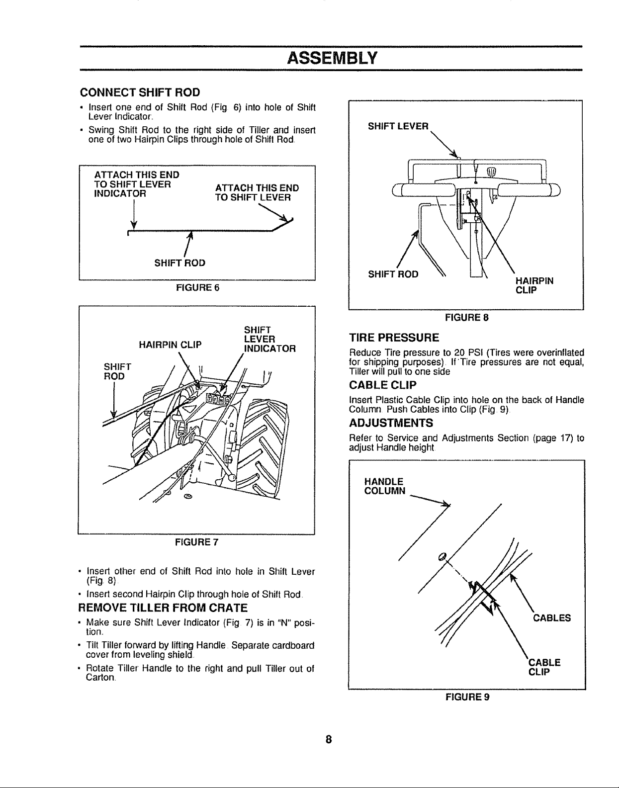
CONNECT SHIFT ROD
, Insert one end of Shift Rod (Fig 6) into hole of Shift
Lever Indicator..
• Swing Shift Rod to the right side of Tiller and insert
one of two Hairpin Clips through hole of Shift Rod.
ATTACH THIS END
TO SHIFT LEVER ATTACH THIS END
INDICATOR TO SHIFT LEVER
' /
SHIFT ROD
FIGURE 6
SHIFT
HAIRPIN CLIP
SHIFT
ROD
LEVER
INDICATOR
SHIFT LEVER
SHIFT ROD
FIGURE 8
TIRE PRESSURE
Reduce Tire pressure to 20 PSI (Tires were overinflated
for shipping purposes). If'Tire pressures are not equal,
Tillerwill pull to one side
CABLE CLIP
Insert Plastic Cable Clip into hoEeon the back of Handle
Column. Push Cables into Clip (Fig. 9)
ADJUSTMENTS
Refer' to Service and Adjustments Section (page 17) to
adjust Handle height
HAIRPIN
CLIP
FIGURE 7
. insert other end of Shift Rod into hole in Shift Lever
(Fig. 8)
• insert second Hairpin Clip throughhole of Shift Rod.
REMOVE TILLER FROM CRATE
• Make sure Shift Lever Indicator (Fig 7) is in "N" posi-
tion._
• Tilt Tiller forward by lifting Handle Separate cardboard
cover from leveling shield.
• Rotate Tiller Handle to the right and pull Tiller out of
Carton
HANDLE
COLUMN
CABLES
CLIP
FIGURE 9
8
- illl i lllU ill LLUIJLIIILILLII,,, " ........... II JlLILll i ,,.,... Illl ILLJLJLJ I,
OPERATION
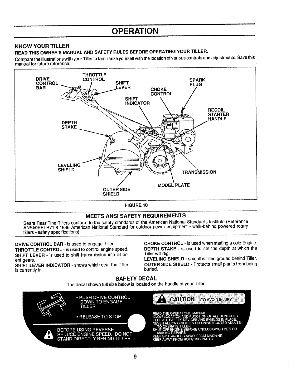
KNOW YOUR TILLER
READ THIS OWNER'S MANUAL AND SAFETY RULES BEFORE OPERATING YOUR TILLER.
ComparetheillustrationswithyourTitierto familiadze yourself-withthelocationofvariouscontrolsandadjustments Save this
manual forfuture reference°
DRIVE CONTROL
THROTTLE
DEPTH
STAKE
LEVELING
SHIELD
SHIFT PLUG
SPARK
LEVER CHOKE
CONTROL
SHIFT
INDICATOR
RECOIL
STARTER
HANDLE
TRANSMISSION
MODEL PLATE
OUTER SIDE
SHIELD
FIGURE 10
MEETS ANS! SAFETY REQUIREMENTS
Sears Rear Tine Tillers conform to the safety standards of the American National Standards Institute (Reference
ANSI/0PE! B71.8-1986 American National Standard for outdoor power equipment - walk-behind powered rotary
tillers- safety specifications),
DRIVE CONTROL BAR - isused to engage Tiller,
THROTTLE CONTROL- is used to control engine speed
SHIFT LEVER - is used to shift transmissioninto differ-
ent gears,
SHIFT LEVER INDICATOR - shows which gear the Tiller
is currently in.
CHOKE CONTROL - isused when starting a cold Engine_
DEPTH STAKE - is used to set the depth at which the
Tiller will dig.
LEVELING SHIELD - smooths tilled ground behind Tiller.
OUTER SIDE SHIELD - Protects small plants from being
buried..
SAFETY DECAL
The decal shown full size below is located on the handle of your Tiller.
9
OPERATION
The operationofany Tiller can resultinforeign objectsthrownintotheeyes, whichcanresultinsevere
eye damage. Always wear safety glasses oreye shields before starting your Tiller andwhile tilling. We
recommend Wide Vision Safety Mask for over the spectacles or standard safety glasses, available at
Sears Retail or Catalog Stores°
HOW TO USE YOUR TILLER
Know how to operate all controlsbeforeadding fuel and
oil or attempting to start Engine. (To stop Engine place
ThrottleControl in STOP position,)
TINE OPERATION - WiTH WHEEL DRIVE
• Always release Drive Control Bar before movingShift
Lever intoanother position,
- Tine movement is achieved by moving Shirt Lever to
"T" positionand engaging Drive ControlBar.,
FORWARD - WHEELS ONLY ! TINES STOPPED
• Release Drive Control Barand move Shift Lever Indi-
cator to "F" position, Engage Drive Control Bar and
Tiller will move forward
REVERSE - WHEELS ONLY / TINES STOPPED
. DO NOT STAND DIRECTLY BEHIND TILLER
• Release the Drive Control Bar
• Move Throttle Control to "SLOW" position..
• Move Shift Lever Indicator to "R" position,
. Hold Drive Control Bar against the Handle (Fig. 11) to
start Tiller movement.,
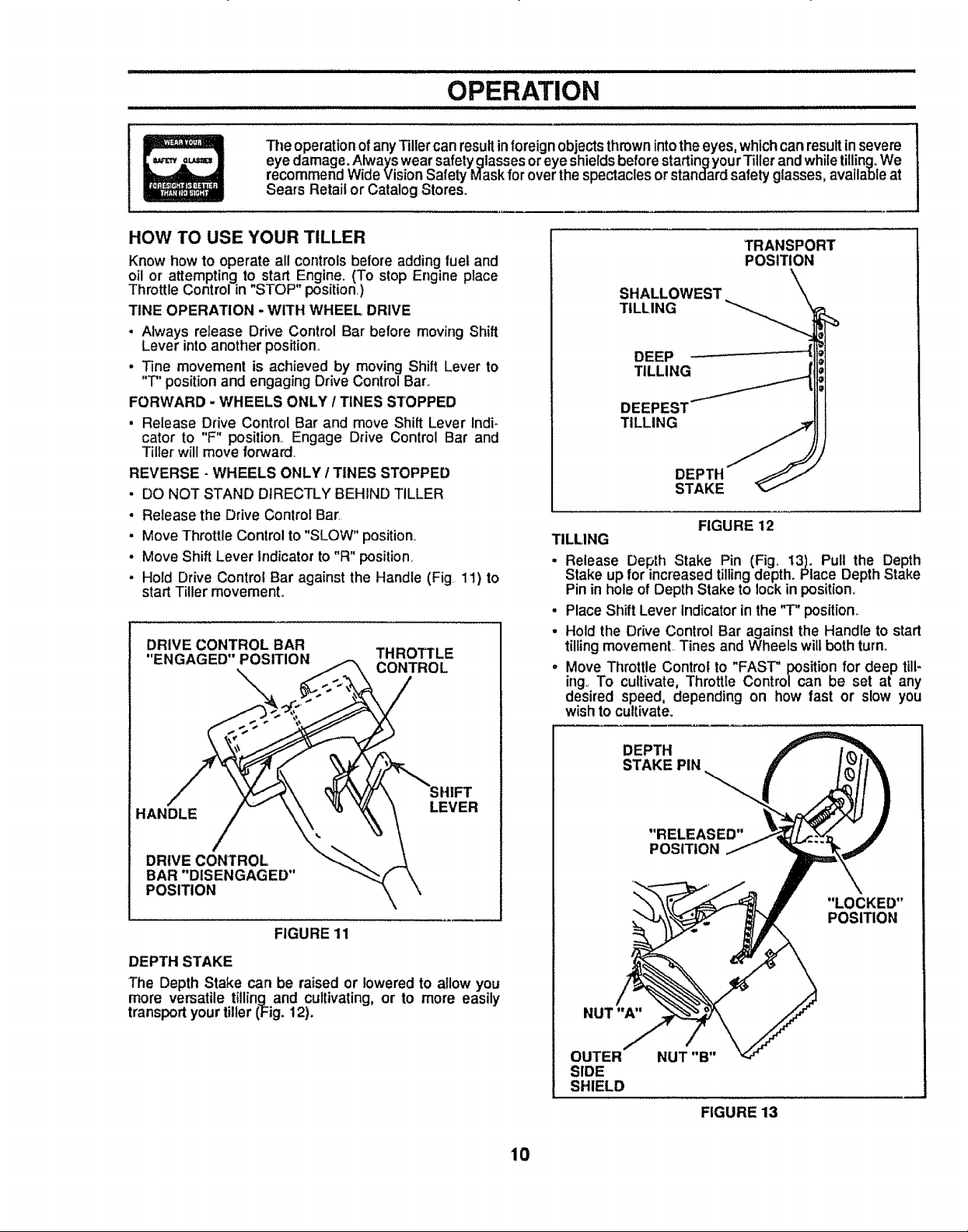
DRIVE CONTROL BAR
TRANSPORT
POSITION
SHALLOWEST
TILLING
DEEP
TILLING
TILLING
DEPTH
STAKE
FIGURE 12
TILLING
. Release Depth Stake Pin (Fig. 13). Pull the Depth
Stake up for increased tilling depth. Place Depth Stake
Pin in hole of Depth Stake to lockin position.
• Place Shift Lever Indicator inthe "T" position..
• Hold the Drive Control Bar against the Handle to start
tilling movement. Tines and Wheels will both turn.,
. Move Throttle Control to "FAST" position for deep till-
ing. To cultivate, Throttle Control can be set at any
desired speed, depending on how fast or slow you
wish to cultivate.
Z
BAR DISENGAGED _ \
POSITION _ \
FIGURE 11
DEPTH STAKE
The Depth Stake can be raised or lowered to allow you
more versatile tilling and cultivating, or to more easily
transportyour tiller (Fig. 12)°
10
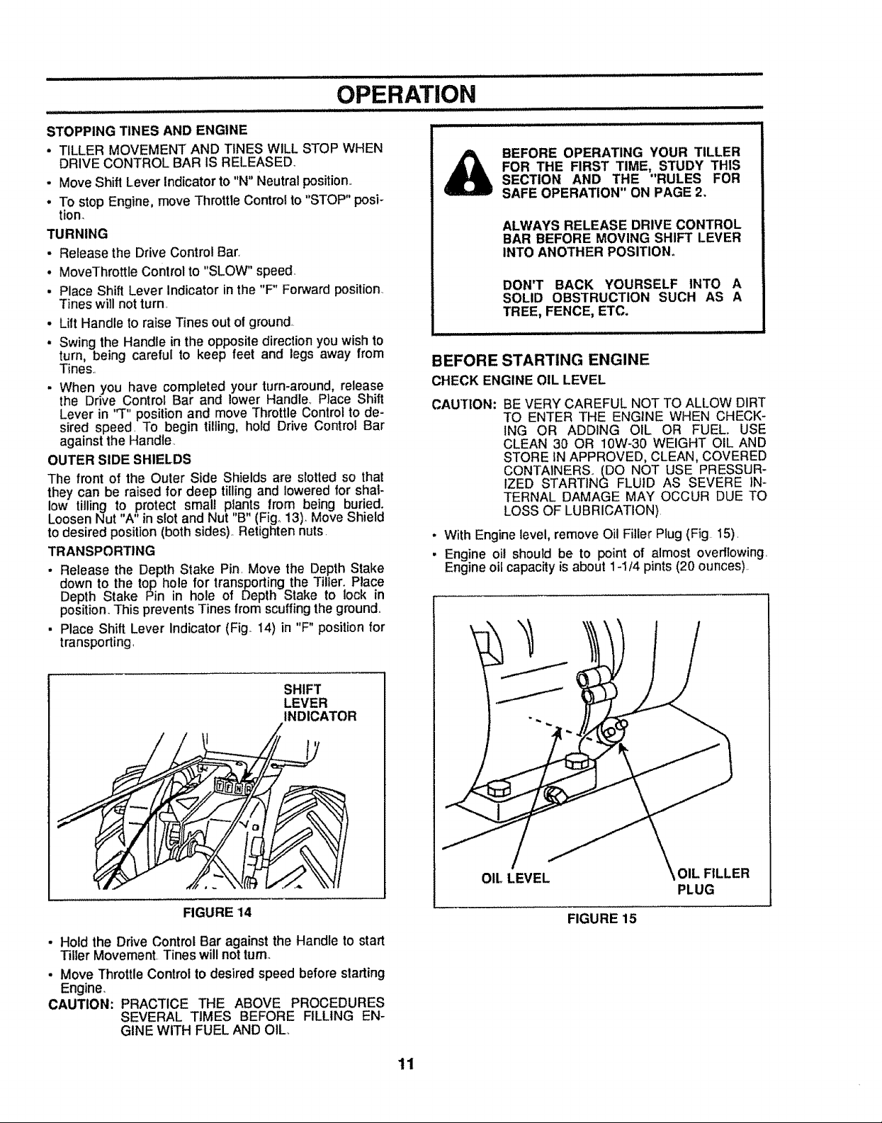
NUT "A"
OUTER
SIDE
SHIELD
DEPTH
STAKE PIN
"RELEASED"
POSITION
"LOCKED"
POSITION
NUT "B"
FIGURE 13
OPERATION
STOPPING TINES AND ENGINE
. TILLER MOVEMENT AND TINES WILL STOP WHEN
DRIVE CONTROL BAR iS RELEASED.
• Move Shift Lever Indicator to "N" Neutral position.,
• To stop Engine, move Throttle Control to "STOP" posi-
tion.
TURNING
• Release the Drive Contro! Bar.
• MoveThrottle Control to "SLOW" speed,
. Place Shift Lever Indicator in the "F" Forward position.
Tines will not turn,
• Lift Handle to raise Tines out of ground,.
• Swing the Handle in the opposite direction you wish to
turn, being careful to keep feet and legs away from
Tines,,
• When you have completed your turn-around, release
the Drive Control Bar and lower Handle., Place Shift
Lever in "T" positionand move Throttle Control to de-
sired speed, To begin tilling, hold Drive Control Bar
against the Handle.,
OUTER SIDE SHIELDS
The front of the Outer Side Shields are slotted so that
they can be raised for deep tilling and lowered for shal-
low tilling to protect small plants from being buried.
Loosen Nut "A" in slot and Nut "B" (Fig. 13). Move Shield
to desired position (both sides).,Retighten nuts.
TRANSPORTING
. Release the Depth Stake Pin, Move the Depth Stake
down to the top hole for transporting the Tiller. Place
Depth Stake Pin in hole of Depth Stake to lock in
position. This prevents Tines from scuffing the ground,,
• Place Shift Lever Indicator (Fig° 14) in "F" position for
transporting,
BEFORE OPERATING YOUR TILLER
FOR THE FIRST TIME, STUDY THIS
SECTION AND THE "RULES FOR
SAFE OPERATION" ON PAGE 2,
ALWAYS RELEASE DRIVE CONTROL
BAR BEFORE MOVING SHIFT LEVER
INTO ANOTHER POSITION°
DON'T BACK YOURSELF INTO A
SOLID OBSTRUCTION SUCH AS A
TREE, FENCE, ETC.
BEFORE STARTING ENGINE
CHECK ENGINE OIL LEVEL
CAUTION: BE VERY CAREFUL NOT TO ALLOW DIRT
TO ENTER THE ENGINE WHEN CHECK-
ING OR ADDING OIL OR FUEL. USE
CLEAN 30 OR 10W-30 WEIGHT OIL AND
STORE IN APPROVED, CLEAN, COVERED
CONTAINERS,, (DO NOT USE PRESSUR-
IZED STARTING FLUID AS SEVERE IN-
TERNAL DAMAGE MAY OCCUR DUE TO
LOSS OF LUBRICATION)
• With Engine level, remove Oil Filler Plug (Fig 15),
• Engine oil should be to point of almost overttowing,
Engine oil capacity is about 1-1/4 pints (20 ounces),
SHIFT
LEVER
INDICATOR
FIGURE 14
• Hold the Drive Control Bar against the Handle to start
Tiller Movement, Tines will not turn
• Move Throttle Control to desired speed before slarting
Engine.
CAUTION: PRACTICE THE ABOVE PROCEDURES
SEVERAL TIMES BEFORE FILLING EN-
GINE WITH FUEL AND OIL,,
OIL LEVEL OIL FILLER
PLUG
FIGURE 15
11
 Loading...