

Craftsman 917298560 Owner’s Manual
OWNER'S
MANUAL
MODEL NO.
917,298560
Caution:
Read and follow
all Safety Rules
and instructions
Before Operating
This Equipment
[RI:IFTXMAN
5.0 HP
17 INCH TINE WIDTH
REAR TINE TILLER WITH
COUNTER ROTATING TINES
Sears, Roebuck and Co., Hoffman Estates, IL 60179 U.S.A.
.............................. IlllllllllllUIUIIIIII
• Assembly
• Operation
° Customer Responsibilities
° Service and Adjustments
° Repair Parts
SAFETY RULES
Safe Operation Practices for Walk-Behind Powered Rotary Tillers
TRAINING
• Read the Owner's Manual carefully. Be thoroughly
familiar with the controls and the proper use of the
equipment. Know how to stop the unit and disengage
the controls quickly.
° Never allow childrentooperate the equipmenL Never
allow adults to operate the equipment without proper
instruction.
o Keepthe area ofoperation clear of al!persons,particu-
larly small children, and pets.
PREPARATION
° Thoroughlyinspectthe area where the equipment isto
be used and remove all foreign objects.
° Disengage all clutches and shift into neutral before
starting the engine (motor).
° Do not operate the equipment without wearing ad-
equate outer' garments. Wear footwear that witl im-
provefooting on slippery surfaces.
o Handle fuel with care; it is highly flammable.,
• Use an approved fuel container'.
,, Never add fuel to a running engine or hot engine_
° Rlt fuel tank outdoors with extreme care. Never fill
fuel tank indoors.
° Replace gasoline cap securely and clean up spilled
fuel before restarting.
° Use extension cords and receptacles as specified by
the manufacturer' for all unitswith electric drive motors
or electric starting motors.
o Never attempt to make any adjustments while the
engine (motor_ is running (except where specificaUy
recommended by manufacturer)_
OPERATION
o Do not put hands or feet near' orunderrotating parts°
• Exercise extreme caution when operating on or cross-
ing gravel drives, walks, or roads. Stay alert for hidden
hazards or traffic° Do not carry passengers.
° After striking a foreign object, stop the engine (motor),
remove the wire from the spark plug, thoroughly in-
spect the tiller for at,,y,damage, and repair the damage
before restarting and operating the tiller°
• Exercise cautionto avoid slipping or falling.
° if the unit should start to vibrate abnormally, stop the
engine (motor) and check immediately for' the cause,
Vibration is generally a warning of trouble.
° Stop the engine (motor) when leaving the operating
position°
° Take all possible precautions when leaving the ma-
chine unattended. Disengage the tines, shift into
neutral, and stop the engine.
o Before cleaning, repairing, or' inspecting, shut off the
engine andmakecertain all moving partshave stopped.
Disconnect the spark plug wire, and keep the wire
away from the plug to prevent accidental starting.
Disconnect the cordon electric motors°
• Do not run the engine indoors; exhaust fumes are
dangerous_
° Neveroperate the tillerwithout proper guards, plates,
or other safety protective devices in place,
° Keepchildren and pets away.
o Do notoverloadthe machinecapac_3'byattemptingto
tilltoo deep at too fast a rate.
= Never operate themachine at highspeeds on slippery
surfaces. Lookbehindand use care when backing.
o Never allow bystanders near the unit.
° Use only attachments and accessories approved by
the manufacturer of the tiller (such as wheel weights,
counterweights, cabs, and the like).
° Never operate the tiller without good visibility or light.
° Be careful when tillingin hard ground, The tines m.ay
catch inthe ground and propel the tiller forward. If this
occurs, let go ofthe handlebars and do not restrain the
machine_
MAINTENANCE AND STORAGE
• Keep machine, attachments, and accessoriesin safe
workingcondition.
° Check shear pins, engine mounting bolts, and other
bolts at frequent intervals for proper tightness to be
sure the equipmentis in safe workingcondition.
• Neverstore the machinewithfuel inthefuel tank inside
a buildingwhereignitionsourcesare present,such as
hot water and space heaters, clothesdryers, and the
like. Allow the engine to cool before storing in any
enclosure_
° Always refer'to the operator's guide instructionsfor'
important details if the tiller is to be stored for an
extended period°
- IMPORTANT -
CAUTION, IMPORTANTS, AND NOTES ARE A MEANS OF ATTRACTING ATTENTION TO IMPORTANT OR CRITI-
CAL INFORMATION IN THIS MANUAL.
IMPORTANT: USED TO ALERT YOU THAT THERE IS A
POSSIBILITY OF DAMAGING THIS EQUIPMENT,
out important safety precautions, it
means --Attention! Become Alert! Your
CAUTION: Look for this symbol to point
safety is involved.
NOTE: Gives essential information that will aid you to better
understand, incorporate, or execute a particular set of instruc-
ttoneo
2
CONGRATULATIONS on your purchase of a Sears Tiller.
it has been designed, engineered and manufactured to
giveyou the best possibledependability and performance°
Should you experience any problemsyou cannot easily
remedy, please contact your nearest authorized Sears
Service Center/Department. They have competent, weiF
trainedtechniciansand the propertoolsto serviceorrepair
this unit.
Please read and retain this manual° The instructionswill
enable you to assemble and maintain your tiller properiy_
Always observe the "SAFETY RULES'L
MODEL
NUMBER 917.298560
SERIAL
NUMBER
DATE OF
PURCHASE
THE MODEL AND SERIAL NUMBERS WILL BE
FOUND ON THE MODEL PLATE ATTACHED TO
THE "TOPOF THE TRANSMISSION_
YOU SHOULD RECORD BOTH SERIAL NUMBER
AND DATE OF PURCHASE ,&kiDKEEP INA SAFE
PLACE FOR FUTURE REFERENCE_
PRODUCT SPECIFICATIONS
HORSEPOWER: 5,0 HP
DISPLACEMENT: 12,,57cuoino
GASOLINE CAPACITY: 3 Quarts
Unleaded Regular
OIL : SAE 30W (Above 32°F)
(CAPACITY: 20 oz ) SAE 5W-30 (Below 32aF)
SPARK PLUG : Champion
(GAP: 030") RJ19LM (STD361458)
MAINTENANCE AGREEMENT
A Sears Maintenance Agreement isavailable onthisprod-
uct. Contact your nearest Sears store for details.
CUSTOMER RESPONSIBILITIES
* Read and observe the safety rules°
, Follow a regular schedule inmaintaining, caring for and
using your tiller_
° Follow the instructions under the "Customer
Responsibilities" and"Storage" sections ofthis Owner's
Manual.
LIMITED TWO YEAR WARRANTY ON CRAFTSMAN TILLER
Fortwo years from date ofpurchase,when thisCraftsman Tilleris maintained,lubricated,and tuned up accordingto
the operating and maintenance instructionsin the owner's manual, Sears will repair free of charge any defect in
material orworkmanship°
This Warranty does not cover:
, Expendable items which become worn during normal use, such as tines, spark plugs, air cleaners and belts.
o Repairs necessary because of operator abuse or negligence, including bent crankshafts and the failure to
maintain the equipment according to the instructionscontained in the owner's manual.
= tf this Craftsman Tiller is used for commercial or rental purposes, this Warranty applies for only 30 days from the
date of purchase.
WARRANTY SERVICE IS AVAILABLE BY RETURNING THE CRAFTSMAN TtLLER TO THE "NEAREST SEARS
SERVICE CENTER/DEPARTMENT IN THE UNITED STATES_ THIS WARRANTY APPLIES ONLY WHILE THIS
PRODUCT tS IN USE INTHE UNITED STATES.
This Warranty gives you specific legal rights,and youmay also have other rights whichvary from state to state.
SEARS, ROEBUCK AND CO., D/817 WA, HOFFMAN ESTATES, ILLINOIS 60179
- IMPORTANT-
This unit is equipped with an internal combustion engine and should not be used onor near any unimproved forest-covered,
brush-covered or grass covered land unless the engine's exhaust system is equipped with a spark arrester meeting
applicable local or state laws (if any). If a spark arrester is used, it should be maintained in effective working order by the
operator.
Inthe state of California the above ls required by law (Section 4442 of the California Public Resources Code). Other states
may havesimilar laws. Federallawsapplyon federallands. SeeyourSearsAuthorizedServiceCentedDepartmentforspark
arrester. Refer to the Repair Parts section of this manual for part number.
3
!.
TABLE OF CONTENTS
11,//u==Jl,,Ju,Jull,JH/,,,Ju,,HU,J,/,III,J,,,,J,,,,H=
SAFETY RULES ............................................................ 2
CUSTOMER RESPONSIBILITIES ...................... 3,13-15
PRODUCT SPECIFICATIONS ....................................... 3
WARRANTY ................................................................... 3
ACCESSORIES ............................................................. 5
ASSEMBLY ................................................................ 6-8
OPERATION ............................................................. 9-12
INDEX
A
Accessories ............................................5
Adjustments:
Carburetor. ............................... 18
Depth Stake ......................................10
Handle Height .......................... 15
Side Shields ......................................11
Throttle .................................... 18
Tines ........................................ 17
V-Belt (Ground Drive) .......................16
Air Cleaner ..........................................14
B
Belt:
Belt Guard .......................................16
Repair Parts...................................22
V-Belt (Ground Drive) .....................16
C
Cooling System ................................14
Controls:
Choke ...........................................................9
Throttle ..........................................9
Drive (Tines) ............................... 9
Cultivating ....................................... 12
Customer Responsibilities:
Air Cleaner. ...................................14
Cooling System ....................... 14
Finish ....................................... 15
Maintenance Schedule ............ 13
Muffler ........................................ 15
Oil Change ......................................14
S ark Plug 15
Trees ......................................... 17
Transmission .............................15
V-Belt (Ground Drive) ................16
D
Depth Stake:
Adjustment ...................................10
Repair Parts ....................................25
E
Engine:
Air Cleaner ................................ 14
Cooling System ............................14
Fuet Type ................................... 11
Engine (cont'd)
Lubrication...................................14
Oil Level.........................................11
Oit Type ...................................t 1,14
Spark Plug ................................ 15
Starting ...................................................12
Stopping ........................................10
Storage .........................................19
Winter Operation ..........................14
Fuel:
FillingTank .................................11
Storage ..............................................19
Type ..............................................11
Finish:
Maintenance ...............................15
Handle:
Height Adjustment ......................15
Repair Parts................................21
Lubrication:
Lubrication Chart ..........................13
Engine ....................................... 14
Muffler:
Maintenance ..............................t5
Spark Arrester, ............................3
Oil:
Level ......................................... 11
Type ...........................................11,14
Operation:
Cultivating ...................................12
Fill Fuel Tank ..................................11
Starting Engine ........................ 12
Stopping Tines & Engine ............10
Tilling............................................10
TillingHints...............................12
Tine Operation .................................t0
Transporting Tiller ....................11
Winter Operation ......................14
MAINTENANCE SCHEDULE ...................................... 13
SERVICE & ADJUSTMENTS ................................. 15-18
STORAGE .................................................................... 19
TROUBLESHOOTING ................................................. 20
REPAIR PARTS-TILLER ........................................ 21-27
REPAIR PARTS-ENGINE ................................ .......28-32
SERVICE/PARTS ORDERING ................ BACK COVER
R
RepairParts:
Tiller.................................................21-27
Engine ................................ 28-32
Rules for' Safe Operation .................. 2
S
Service & Adjustments:
F
H
L
M
O
Carburetor. ...............................18
HandleHeight..................................15
Side Shtetds .............................11
Throttle .......................................18
Tines................................................17
V.,Belt (Ground Drive) ...............16
Wheels ............................................15
Service:
Repair Parts .........................21-32
Service Record .............................13
Shear Pins:
Operation .........................................12
Repair Parts .............................. 26
Spark Plug:
Gap ................................................3
Mamtenance ............................ 15
Storage:
Fuel System ..............................19
Tiller ......................................... 19
T
Tilling....................................................i0,12
Tines:
Arrangement/Replacement ...... 17
Operation......................................I0
Repair' Parts ............................. 26
Shear'Pins...............................12
Transmission'.
Maintenance ...............................15
Repair Parts ............................. 24
Troubleshooting ..............................20
Transporting ..................................... 11
W
Warranty ...............................................3
Wheels:
Removal ................ ................... 15
Repair Parts.............................. 23
4
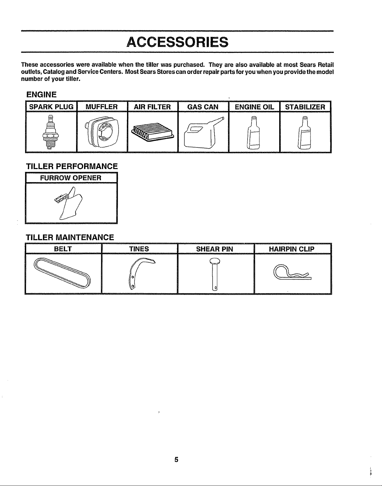
These accessories were available when the tiller was purchased. They are also available at most Sears Retail
outlets, Catalog and Service Centers. Most Sears Stores can order repair parts for you when you provide the model
number of your tiller.
ENGINE
SPARK PLUG
MUFFLER AIR FILTER GAS CAN
6
TILLER PERFORMANCE
FURROW OPENER
TILLER MAINTENANCE
,,, ,,,, ,, , ,,,
, , ,,, ,,,,,,,,, ,
TINES SHEAR PIN
'IIH" I
ENGINE OIL
"A="PmNCLIP
......................i1,1,
STABILIZER
0_
5
IViBLY
Your'new tiller has been assembled atthefactory withexception of thosepartsleft unassembled for shipping purposes. To
ensure safe and properoperation ofyourtillerall parts and hardware you assemble must be tightened securely, Use the
correcttools as necessary to insurepropertiglltness,
TOOLS REQUIRED FOR ASSEMBLY
A socketwrench set willmake assemblyeasier, Standard
wrench sizes are listed.
(t) Utilityknife
(1) Wire cutter
(1) Screwdriver
(1) Tire pressure gauge
(1) Pairof pliers
(1) 9/16" wrench
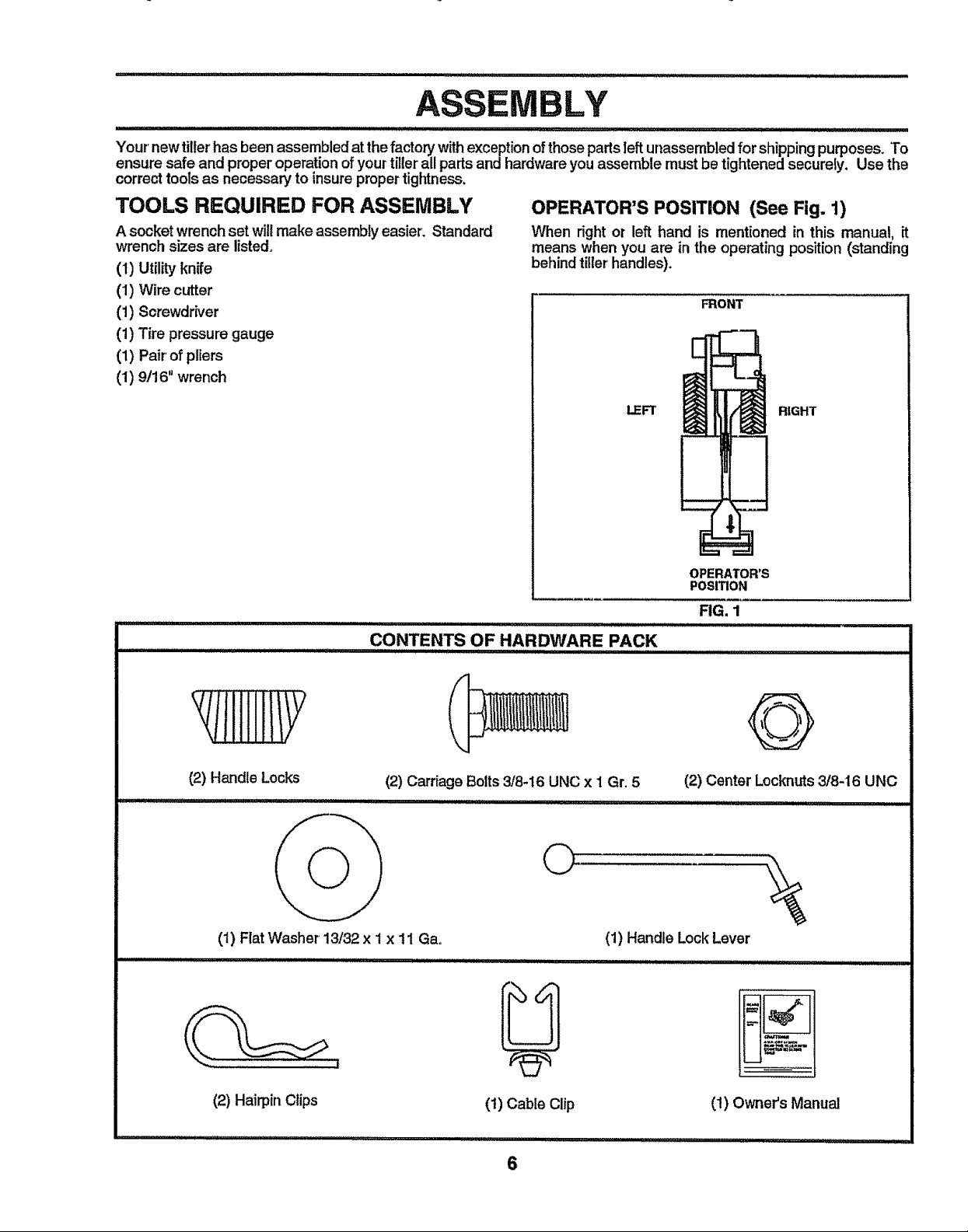
OPERATOR'S POSITION (See Fig. 1)
When right or left hand is mentioned in this manual, it
means when you are in the operating position (standing
behindtiller handles).
FRONT
LEFT RIGHT
CONTENTS OF HARDWARE PACK
(2) Handle Locks
(t) Fiat Washer 13/32 x 1x 11 Gao
_ 7 IIIIIIIIIIII IIII II II LJ
IIIIIIIIIIIIII II LI IIII I I I , iiiiiiii I i, II .....................................
(2) Carriage Bolts3/8-16 UNC x i Gr. 5
©
(1) Handle Lock Lever
OPERATOR'S
POSITION
FIG, 1
@
(2) Center Locknuts3/8-16 UNC
(2) Hairpin Clips
U
(!) Cable Clip
6
(1) Owner's Manual
i,iiiil,l,,i................
ASS
UNPACKING CARTON (See Fig. 2)
CAUTION: Be careful of exposed
l& ...........I
IMPORTANT: WHEN UNPACKING AND ASSEMBLING
TILLER, BE CAREFUL NOT TO STRETCH OR KINK
CABLES.
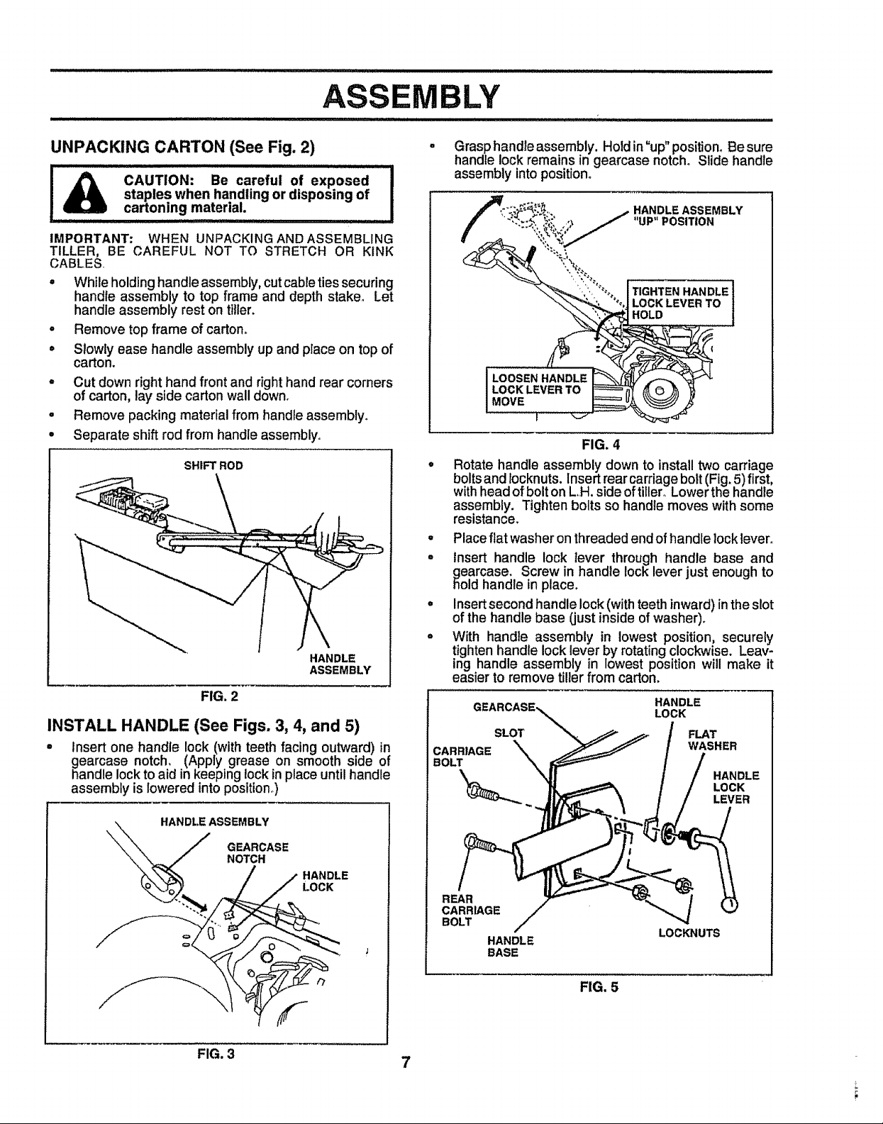
o Whileholdinghandleassembly, cutcabletiessecuring
handle assembly to top frame and depth stake. Let
handle assembly reston tiller.
• Remove top frame of carton.
= Slowly ease handle assembly up and place on top of
carton.
- Cut down right hand front and right hand rear corners
of carton, lay side carton wall down.
° Remove packing material from handle assembly.
° Separate shift rod from handle assembly°
INSTALL HANDLE (See Figs. 3, 4, and 5)
= Insert one handle lock (withteeth facing outward) in
gearcase notch. (Apply grease on smooth side of
handle locktoaid in keeping lockinplace untilhandle
assembly is lowered into position,)
staples when handling or disposing of
cartoning material.
SHIFT ROD
HANDLE
ASSEMBLY
FIG. 2
LY
Grasphandle assembly. Hold in"up"position° Be sure
handle lock remains in gearcase notch. Slide handle
assembly into position.
HANDLE ASSEMBLY
"UP" POSITION
TIGHTEN HANDLE]
LOCK LEVER TO /
HOLD |
FIG. 4
° Rotate handle assembly down to installtwo carriage
bolts and Iocknuts. Insertrearcarriagebolt(Fig.5) first,
withheadof bolt onL,H. side oftitlero Lower the handle
assembly. Tighten bolts so handle moves with some
resistance.
° Placeflat washer onthreaded endof handle locklever,
° Insert handle lock lever through handle base and
gearcase. Screw in handle lock lever just enough to
hold handlein place.
° Insertsecondhandle lock(withteethinward)inthe slot
of the handle base (just inside of washer).
° With handle assembly in lowest position, securely
tighten handle lock lever by rotatingclockwise. Leav-
ing handle assembly in lowest position will make it
easier to remove tillerfrom carton.
HANDLE
LOCK
SLOT
CARRIAGE
BOLT
FLAT
WASHER
HANDLE
LOCK
LEVER
_,,,..\ HANDLE ASSEMBLY
\"_\\. / GEARCASE
"-\ "--.._/ NOTCH
FIG. 3
7
REAR
CARRIAGE
BOLT
HANDLE
BASE
LOCKNUTS
FIG. 5
BLY
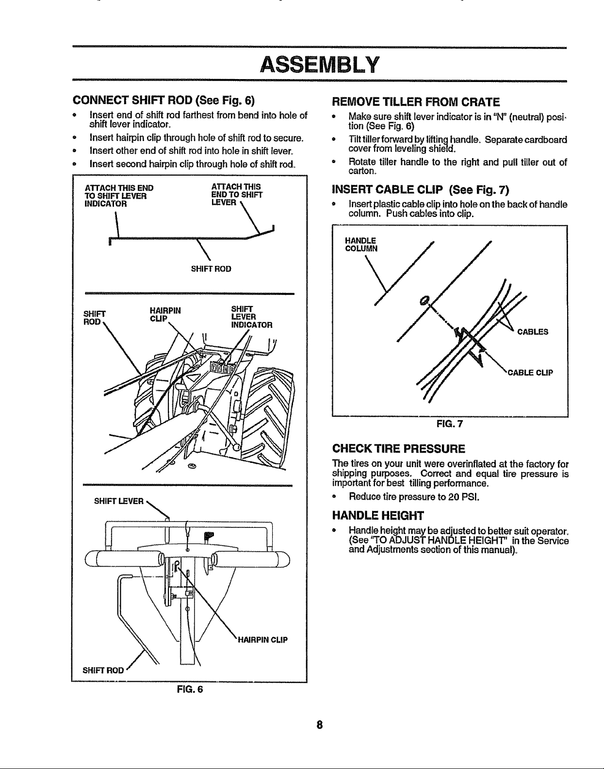
CONNECT SHIFT ROD (See Fig. 6)
,, Insert end of shift rod farthest from bend into hole of
shift lever indicator,.
= Insert hairpin clipthrough holeof shift rodto secure,
• Insert other end of shift rodintohole in shiftlever°
- Insert second hairpin clipthrough hole of shift rod.
ATTACHTHIS END
TO SHIFT LEVER
ATrACH THIS
ENDTO SHIFT
\
SHIFT ROD
SHIFT
H/IJRPIN
CUP
SHIFT
LEVER
INDICATOR
REMOVE TILLER FROM CRATE
• Make sure shiftlever indicator is in "N" (neutral) posi-
tion (See Fig. 6)
• Tilt tillerforward by liftinghandle, Separate cardboard
cover from levelingshield,
° Rotate tiller handle to the right and pull tiller out of
carton.
INSERT CABLE CLiP (See Fig. 7)
• Insertplasticcable clipintoholeon the back ofhandle
column, Pushcables intoclip.
SHIFTLEVER
SHIFT ROD
FIG. 7
CHECK TIRE PRESSURE
The tireson your unit were overinflated at the factory for
shipping purposes, Correct and equal tire pressure is
importantfor best tilling performance.
° Reduce tire pressure to 20 PSI.
HANDLE HEIGHT
Handle height may be adjusted to better suitoperator_
(See WO ADJUST HANDLE HEIGHT" in the Service
and Adjustmentssection of this manual)°
HNRPIN CLIP
FIG. 6
8
OPERATION
.........,,,,,.lll l ill,ll i ,,/,,,/
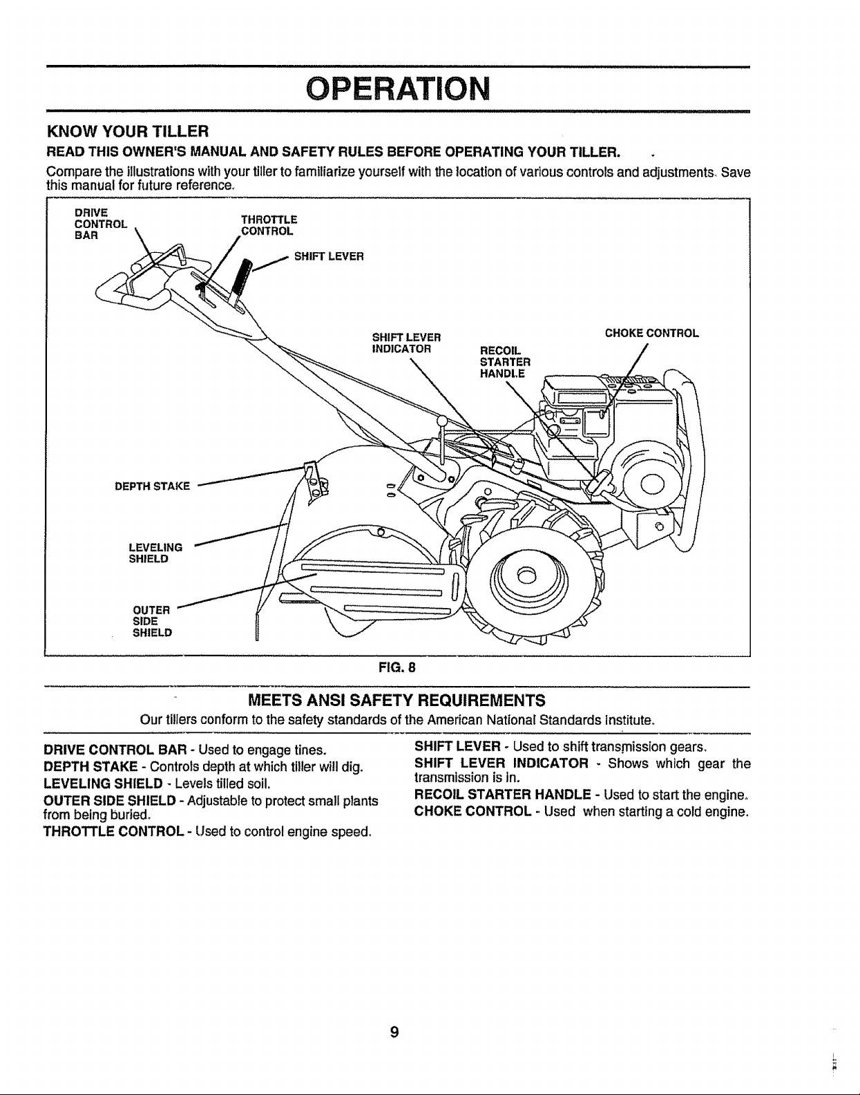
KNOW YOUR TILLER
READ THIS OWNER'S MANUAL AND SAFETY RULES BEFORE OPERATING YOUR TILLER.
Compare the illustrationswithyourtillerto familiarize yourselfwiththe location of variouscontrols and adjustments_ Save
this manual for future reference_
DRIVE
CONTROL THROTTLE
BAR CONTROL
SHIFT LEVER
SHIFT LEVER
INDICATOR
DEPTH STAKE
LEVELING
SHIELD
OUTER
SIDE
SHIELD
RECOIL
STARTER
HANDLE
FIG. 8
MEETS ANSI SAFETY REQUIREMENTS
Our tillersconformtothe safety standards of the American National Standards Institute°
CHOKE CONTROL
DRIVE CONTROL BAR - Used to engage tines.
DEPTH STAKE - Controls depth at which tiller will dig.
LEVELING SHIELD - Levels tilled soil.
OUTER SIDE SHIELD - Adjustable toprotect small plants
from being buried.
THROTTLE CONTROL- Used to control engine speed.
SHIFT LEVER - Used to shifttransmission gears,
SHIFT LEVER INDICATOR - Shows which gear the
transmissionis in,
RECOIL STARTER HANDLE - Usedto start the engine,
CHOKE CONTROL - Used when starting a cold engine,
9
OPE N
The operation of any tiller can result in foreign objects thrown into the eyes, which can
result in severe eye damage. Always wear safety glasses or eye shields before starting
your tiller and while tilling. We recommend wide vision safety mask for over the spec-
tacles or standard safety glasses.
HOW TO USE YOUR TILLER
Know flow to operate all controls before adding fuel and
oil or attempting to start engine.
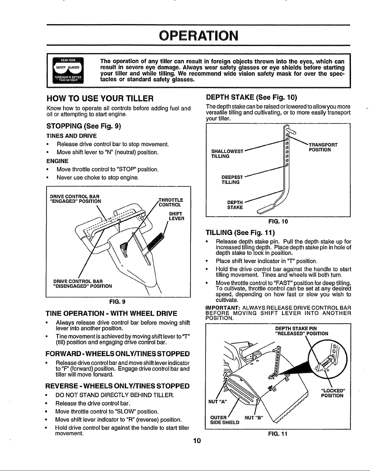
STOPPING (See Fig. 9)
"i"INESAND DRIVE
= Release drive control bar to stop movemenL
° Move shift lever to "N" (neutral) position_
ENGINE
° Move throttle controlto "STOP"position.
• Never use choke to stop engine.
TINE OPERATION - WITH WHEEL DRIVE
• Always release drive controlbar before moving shift
lever into another position,
• Tine movement isachieved bymovingshiftleverto=r'
(til!) position and engaging drive control bar.
FORWARD- WH EELS ONLY/TINES STOPPED
= Release drivecontrolbarand move shiftlever indicator
to"F" (forward)position. Engage drive controlbar and
tiller will move forward.
DEPTH STAKE (See Fig, 10)
The depthstake can be raised orloweredto allowyou more
versatiletillingand cultivating, or to more easily transport
rout tiller.
SHALLOWEST
TILLING
DEEPEST
TILLING
DEPTHSTAKE
FIG. 10
POSITION
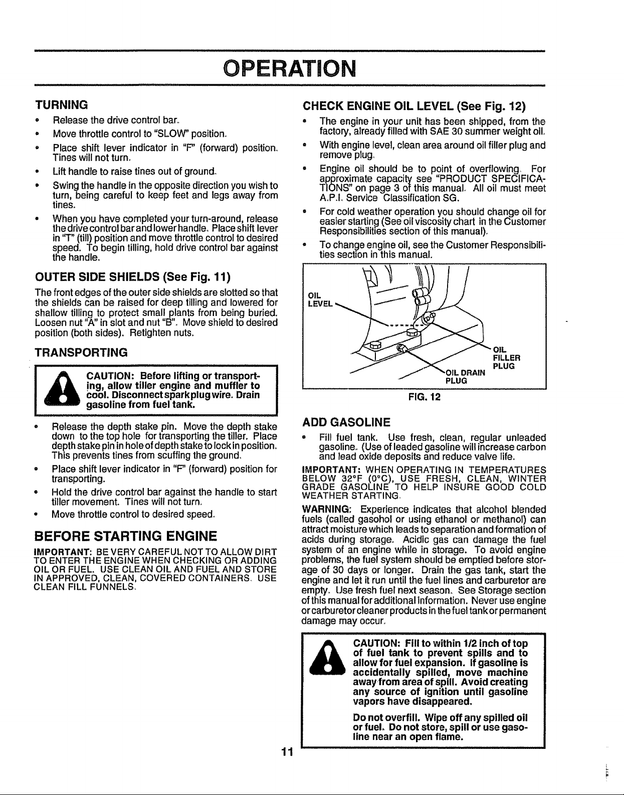
TILLING (See Fig. 11)
° Release depth stake pin. Pull the depth stake up for
increasedtillingdepth. Placedepth stakepinin hole of
depth stake to lockin position.
° Place shift lever indicator=in '3" position.
° Holdthe drive control bar against the handle to start
tilling movement. Tines and wheels willboth turn
° Movethrottlecontrolto"FAST" positionfor deep tilling.
To cultivate,throttlecontrol can be setat any desired
speed, depending on how fast or slow you wish to
cultivate.
IMPORTANT: ALWAYS RELEASE DRIVE CONTROL BAR
BEFORE MOVING SHIFT LEVER INTO ANOTHER
POSITION°
DEPTH STAKE PiN
"RELEASED" POSITION
\
\
REVERSE- WHEELS ONLY/TINES STOPPED
° DO NOT STAND DIRECTLY BEHIND TILLER.
° Release the drive control bar.
• Move throttlecontrolto "SLOW" position°
• Move shiftlever indicator to "R" (reverse) position.
o Hold drive controlbar against Lhehandle tostart tiller
movement,
"LOCKED"
POSITION
NUT"a"
SIDESHIELD
FIG. 11
10
OPERATION
TURNING
o Release the drive control bar°
o Move throttle control to "SLOW" position.
° Place shift lever indicator in "F" (forward) position_
Tines will not turn°
° Lift handteto raise tines out of ground°
= Swingthe handle in the oppositedirection youwishto
turn,being careful to keep feet and legs away from
tines,
• When you have completed yourturn-around, release
thedrivecontrolbarand lower handleoPlaceshiftlever
in "T" (till)positionand movethrottlecontroltodesired
speed. To begin tilling, hold drivecontrolbar against
the handle°
OUTER SIDE SHIELDS (See Fig. 11)
The front edges of the outer sideshieldsare slottedsothat
the shields can be raised for deep tillingand loweredfor
shallow tilling to protect small plants from being buried.
Loosen nut 'W' inslotand nut "B"oMove shieldto desired
position(both sides). Retighten nuts.
TRANSPORTING
ing, allow tiller engine and muffler to
_ CAUTION: Before lifting or transport-
tool. Disconnectsparkplugwireo Drain
gasoline from fue! tank,
- Release the depth stake pin, Move the depth stake
down to the top hole for transportingthe tiller. Place
depthstake pln inhole of depth stake to lock in position,
This prevents tines from scuffing the ground,
• Place shift lever indicator in "F" (forward) position for
transporting.
o Hold the drive control bar against the handle to start
tiller movement. Tines will not turn.
o Move throttle control to desired speed,
BEFORE STARTING ENGINE
IMPORTANT: BE VERY CAREFUL NOT TO ALLOW DIRT
TO ENTER THE ENGINE WHEN CHECKING OR ADDING
OIL OR FUEL. USE CLEAN OIL AND FUEL AND STORE
IN APPROVED, CLEAN, COVERED CONTAINERS. USE
CLEAN FILL FUNNELS,,
CHECK ENGINE OIL LEVEL (See Fig. 12)
• The engine in your unit has been shipped, from the
factory, aiready filled with SAE 30 summer weightoilo
= With engine level, clean area aroundoilfiller plug and
remove plugo
° Engine oil should be to point of overflowing, For
approx!mate capacity see "PRODUCT SPECIFICA-
TIONS on page 3 of this manual All oil must meet
AoP.IoService Classification SG.
= For cold weather operation you should change oil for
easier starting(See oilviscositychart in the Customer
Responsibilitiessectionof thismanual).
° To change engine oil, see the Customer Responsibili-
ties section in this manual.
OIL
OIL
FILLER
PLUG
PLUG
FIG. 12
ADD GASOLINE
° Fill fuel tank. Use fresh, clean, regular unleaded
gasoline,_ (Use of leaded gasoline will increase carbon
and lead oxide deposits and reduce valve life.
IMPORTANT= WHEN OPERATING IN TEMPERATURES
BELOW 32aF (0aC), USE FRESH. CLEAN, WINTER
GRADE GASOLINE TO HELP INSURE GOOD COLD
WEATHER STARTING,
WARNING: Experience indicates that alcohol blended
fuels (called gasohol or using ethanol or methanol) can
attractmoisturewhich leads to separationandformation of
acids during storage. Acidic gas can damage the fuel
system of an engine while in storage. To avoid engine
problems, the fuel system shouldbe emptied before stor-
age of 30 days or longer. Drain the gas tank, start the
engine and let it run untilthe fuellinesand carburetor are
empty° Use freshfuel next season. See Storage section
ofthismanualforadditionalinformation. Never useengine
orcarburetorcleanerproductsinthefuel tankorpermanent
damage may occur.
11
of fuel tank to prevent spills and to
CAUTION: Fill to within 1/2 inch of top
allow for fuel expansion. If gasoline is
accidentally spilled, move machine
away from area of spill. Avoid creating
any source of ignition until gasoline
vapors have disappeared.
Do not overfill. Wipe off any spilled oil
or fuel. Do not store, spill or use gaso-
line near an open flame.
 Loading...