

Craftsman 917298231 Owner’s Manual
_/A/,_
OWNER'S
MANUAL
MODEL NO.
917.298231
• / t_J f ___
Place Photo Here
Caution:
Read and follow
all Safety Rules
and Instructions
Before Operating
This Equipment
3,0 HORSEPOWER
17 RNCH Tt E WIDTH
FRONT TNNE TALLER
Assembly
Operation
Maintenance
Service and Adjustment
Repair Parts
Sears, Roebuck and Co,, Chicago, IL 60684 UoS.A,
SAFETY RULES
_2-'_} Safe Operation Practices for Walk-Behind Powered Rotaiy Tillel s _._,_l_._i},'_
]'RAINING
Read the operating and service instruction manual
carefully Be thoroughly familiar wilh the controls end
the proper use of the equipment Know how to slop the
unit and disengage the controls quickly
Never allow children to operate Ihe equipment Never
allow adults to operale the equipment without proper
instruction.
Keep the area of operation clear of all persons, particu-
larly small children, and pets
PREPARATION
• Thoroughly inspect the area where the equipment_isto
be used and remove all foreign objects.
Disengage all clutches and shill into neutral before
starting the engine (motor)
Do not operate the equipment without wearing ade-
quate outer garmenls. Wear footwear that will improve
footing on slippery s_daces.
• Handle fuel with:care; it is highly flammable
• Lisa an ap.prbved fue .con alner
Never add fuel to a running engine or hot engine.
Fill fuel tank outdoors with extreme care Never fill
fuel tank indoors
Replace gasoline cap securely and clean up spilled
fuel before restading.
• Use extension cords and receptacles as specified bythe
manufacturer for all units with electric drive motors or
electric starting motors.
• Never attempt to make any adjustments while the engine
(motor) is running (except where specifically recom-
mended by manutacturer).
OPERATION
• Do not put hands or feet near or under rotating parts
• Exercise extreme caution when operating on or crossing
gravel drives, walks, or roads Stay alert for hidden
hazards or traffic. Do not carry passengers.
• After striking a foreign object, stop the engine (motor),
remove the wire from the spark plug, thoroughly inspect
the tiller for any damage, and repair the damage before
restariing and operating the tiller.
• Exercise caution to avoid slipping or failing
• !l the unit should stad to vibrate abnomlally, stop the
engine (motor) and check immediately for the cause Vi-
bration is generally a warning of trouble.
• Slop the engine (motor) when leaving the operating
position, before unclogging the tines, and when making
any repair, adjuslments, and inspections
• "Fakeall possible precautions when leaving the machine
unattended Disengage Ihe power take-off, lower the
attachment, shift into neutral, stop the engine, and
remove the key
• Before cleaning, repairing, or inspecting, shut off [he
engine and make certain all moving parts have stoppe&
Disconnect the spark plug wire, and keep thewire away
from the plug lo prevent accidental starting. Disconnec!
the cord on electric molors.
• Do not run the engine indoors; exhaust fumes are dan-
gerous.
• Never operate the tiller wilhout proper guards, plates, or
other safety protective devices in place
• Keep children and pets away
• Donot overload the machine capacity by attempting totill
too deep at too fast a rate
• Never allow bystanders near the unit
• Use only attachments and accessories approved by the
manufacturer ofthetiller (such aswheelweighls, co_ "-
weights, cabs, and the like).
• Never operate the tiller without good visibilily or light
, Be careful when tilling in hard ground. Tile tines may
catch in the ground and propel the tiller forward. If this
occurs, let go of the hand!ebars and do not restrain the
machine.
MAINTENANCE ANDSTORAGE
• Keep machine, attachments, and accessories in safe
working condition_
• Check shear bolts, engine mounting bolts, and other
bolts at frequenl intervals lor proper tightness to be sure
the equipment is in safe working condition.
• Never store the machine with fuel in the fuel lank inside
abuilding where ignition sources are present, such as hol
waler and space heaters, clothes dryers, and the like
Allow the engine to cool before storing in any enclosure
• Always refer to the operalor's guide instructions for
important details ifthe tiller is tobe stored for an extended
period
-IMPORTANT
Warnings, Cautions, and Notes are a means of attracting altention to important or critical information in this manual
LOOK FOR THIS SYMBOL TO POINT
OUT IMPOR'rANT SAFETY PRE-
CAUTIONS. IT MEANS -- ATTENTION!
BECOME ALERT! YOUR SAFETY IS
INVOLVED.
CAUTION: USED TO ALERT' YOU THAT ]'HERE IS
NOTE: Gives essential information that will aid you to
better understand, incorporate, or execute a particular
set of instructions
2
A POSSIBILITY OF DAMAGING ':
EQUIPMENT
CONGRAI_ULATIONS on your purchase of a Sears
Craftsman "Filler. il has been designed, engineered and
manufactured to give you the best possible dependabilily
and pedormance
Should you experience any problems you cannot easily
remedy, please contact your nearest Sears Service Cen-
ter/Depadment We have compelenl, well trained techni-
cians and the proper tools to service or repair this unit
Please read and retain this manual. The instructions will
enable you to assemble and maintain your Tiller prop-
erly Always observe the "SAFETY" RULES"
MODEL
NUMBER 917 298231
SERIAL
NUMBER
DATE OF
PLtRCHASE
THE MODEL AND SERIAL NUMBEFiS WILL BE
FOUND ON THE MODEL PLATE ATTACHED TO
THE RIGHT HAND ENGINE BRACKET_
YOU SHOULD RECORD BOTH SERIAL NUMBER
AND DATE OF PURCHASE AND KEEP tN A SAFE
PLACE FOR FUTURE REFERENCE.
MAINTENANCE AGREEMENT
A Sears Maintenance Agreement is available on this
product. Contact your nearest Sears store for delails
CUSTOMER RESPONSIBILITIES
. Read and observe the safety rules.
• Fellow a regutar schedule in maintaining, caring for and using your Tiller,
• Follow the instructions under "Maintenance" and "Storage" sections of this Owner's Manuat,
PRODUCT SPECIFICATIONS
HORSEPOWER: 30 HP
DISPLACEMENT: 7 75 CU IN
GASOLINE CAPACITY: 2 QUART
OIL (20 OZ CAPACITY): SAE 30W
SPARK PLUG (GAP 030 IN): CHAMPION
(UNLEADED)
(SAE 10W 30)
RCJ8
LIMITED ONE YEAR WARRANTY ON CRAFTSMAN TILLER
For one year from date o purchase when this Craftsman Tiller is maintained lubricated, and tuned up ac-
cording to the instructions in the owner s manual, Sears will repair, free of charge, any defect in material and
workmanship.
If this Craftsman Tiller is used for commerc[a! or rental purposes, this Warranty applfes for only 30 days from
the date of purchase
This Warranty does not cover:
• expendable items which became worn during normal use, such as tines, spark plug, air cleaners and belts.
- Repairs necessary because of operator abuse or negligence, including bent crankshafts and the failure to
maintain the equipment according to the instructions contained in the owner's manual
WARRANTY SERVICE IS AVAILABLE BY RETURNING THE CRAFTSMAN TILLER TO THE NEAREST
SEARS SERVICE CENTER/DEPARTMENT IN THE UNITED STATES THIS WARRANTY APPLIES ONLY
WHILE THIS PRODUCT IS IN USE IN THE UNITED STATES.
This Warranty gives you specific legal rights, and you may atso have other rights which vary from state to
state
Sears, Roebuck and Co, D/731CR-W, Sears Tower, Chicago, IL 60684
-NOTE-
Th sun t s equipped w th an in erna con busl on engine and should not be used on or near any unimproved forest-
covered brush-covered or grass covered and unless he eng ]es exhaust system is equipped with a spark arrester
meeting applicable local or state aws (any) t a spark arrester is used, it should be maintained in effect ve working order
by the operator
In the state of California the above is required by law (Section 4442 of the California Public Resources Code) Other
s ares may have similar laws. Federal laws apply on federal lands See your Sears Aulhodzed Service Cenler for spark
attester Refer 1opage 31 of Repair Pads section of lhis manual for part number
3
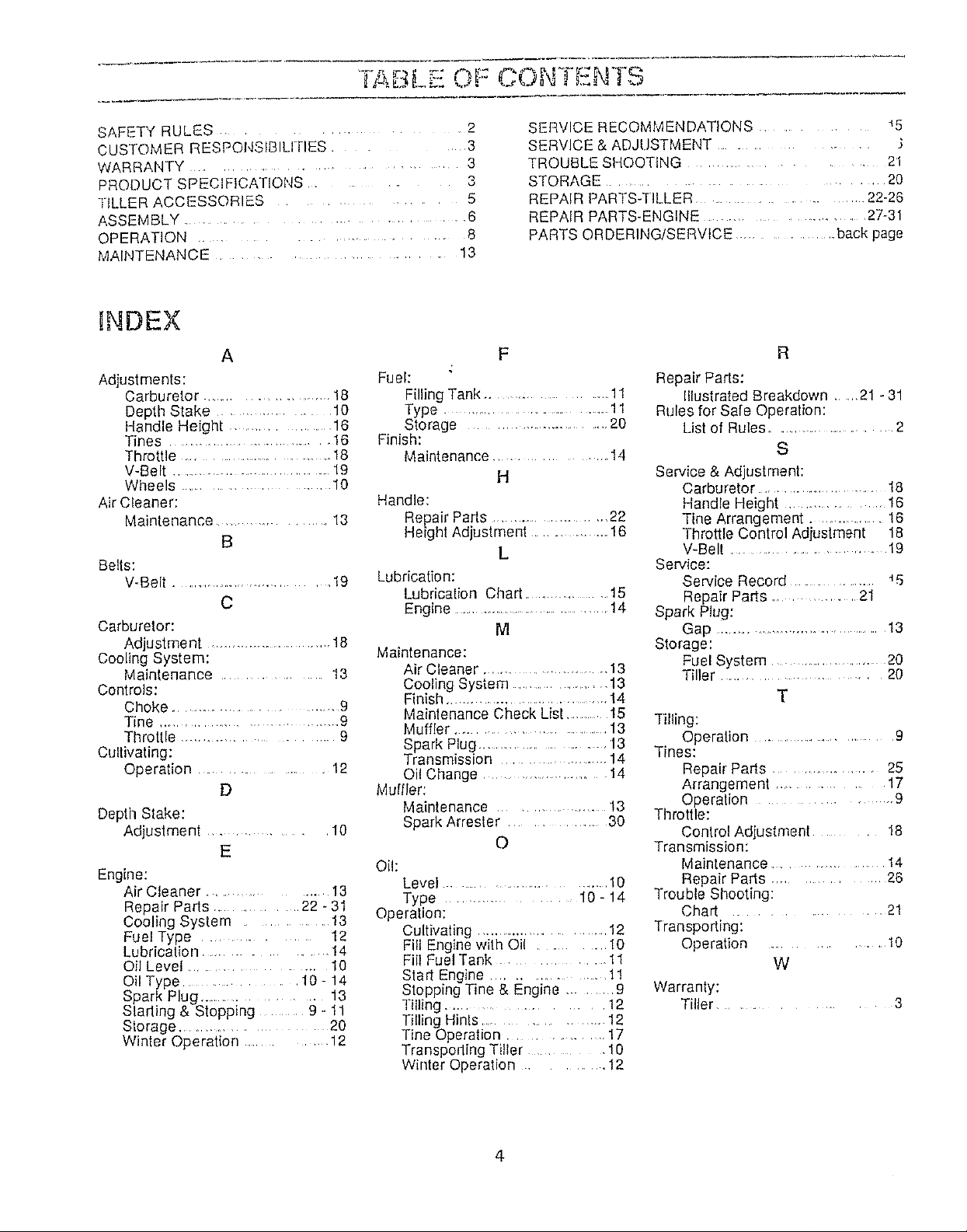
ABL . OF C(aN I=NTS
SAFETY RULES ............ 2
cuSTOMER RESPONStBILI RES ............ 3
WARRANTY .............................
PRODUCT SPECIFICATIONS .................. 3
TILLER ACCESSORIES ........... 5
ASSEMBLY .............................................. 6
OPERATION ............................. 8
MAINTENANCE ......................... 13
HNDEX
A
Adjustments:
Carburetor .......................... 18
Depth Stake ................ 10
Handle Height .................... 16
Tines .................................. 16
Throttle ...................................... 18
V-Belt .................................. 19
Wheels ...................................... 10
Air Cleaner:
Maintenance ................ 13
B
Belts:
V-Belt .............................. 19
C
Carburetor:
Adjustment ............................... 18
Cooling System:
Maintenance ............ 13
Controls:
Choke .............................. 9
Tine ................................... 9
Throttle ................................... 9
Cultivating:
Operation .................. 12
D
Depth Stake:
Adjustment ............. 10
E
Engine:
Air Cleaner ............... I3
Repair Parts .......... 22 - 31
Cooling System .............. 13
Fuel Type ....................... 12
Lubrication .............. !4
Oil Level ............................. 10
Oil Type ................. 10- 14
Spark Plug ................. 13
Stading & Stopping .... 9 - 11
Storage .................... 20
Winler Operation ............ 12
Fuel:
Filling Tank ................. 11
Type ................................................! 1
Storage ................................... 20
Finish:
Maintenance .................. 14
Handle:
Repair Parts ......................... 22
Heigh! Adjuslment ............. 16
Lubrication:
Lubrication Chart ........................15
Engine ..................................... 14
Maintenance:
Air Cleaner ....................... 13
Cooling System .................... 13
Finish ...................................... 14
Maintenance Check List ...........15
Muffler ............................ 13
Spark Plug ...................... 13
Transmission ..................... 14
Oil Change ...................... 14
Muffler:
Maintenance ................... 13
Spark Arrester .............. 30
Oil:
Level .............................. 10
Type ................. 10 - 14
Operation:
Cultivating ............................ 12
Fill Engine with Oil .......... t0
Fill Fuel Tank ........... 11
Start Engine .............. 1!
Stopping Tine & Engine ...... 9
Tilling .................... 12
Tilling Hinls .............. 12
Tine Operation. 17
Transporting Tiller .................. 10
Winter Operation ............. 12
SERVICE RECOMMENDATIONS .................. 45
SERVICE & ADJUSTMENT ............................ .}
3
TROUBLE SHOOTING ........................... 21
STORAGE ....................................... 20
REPAIR PARTS-TILLER ..................... 22-26
REPAIR PARTS-ENGINE ......................... 27-31
PARTS ORDERING/SERVICE ................. back page
R
Repair Parts:
Illustrated Breakdown ..... 21 - 31
Rules for Safe Operation:
List of Rules ........................ 2
S
H
L
M
Service & Adjustment:
Carburetor .......................... 18
Handle Height ................. 16
Tine Arrangement .............. 16
Throttle Control Adjustment 18
V-Belt ........................... 19
Service:
Service Record ..................... _5
Repair Parts ................ 21
Spark Plug:
Gap ...................................... 13
Storage:
Fuel System ..................... 20
Tiller ......................... 20
T
Tilling:
Operation ....................... 9
Tines:
Repair Parts ..................... 25
Arrangement .................... 17
Operation .......................... 9
Throttle:
O
Control Adjustment ............ 18
Transmission:
Maintenance ................... t 4
Repair Parts ............. 26
Trouble Shooting:
Chart .............. 21
Transporting:
Operation ............... 10
W
Warranty:
Tiller ....................... 3
4
TILLER AOt, ESSOR]Eo
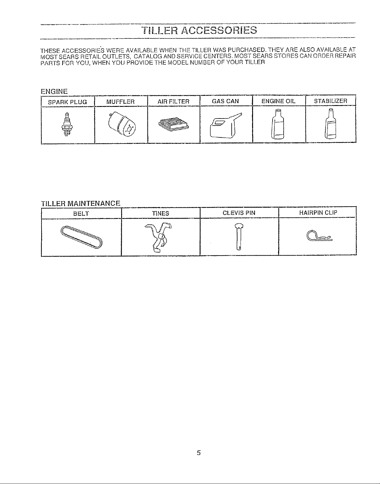
THESE ACCESSORIE_S WERE AVAILABLE WHEN FHE TILLER WAS PURCHASED. THEY ARE ALSO AVAILABLE AT
IviOST SEARS RETAfL OUTLETS, CATALOG AND SERVICE CENTERS. MOST SEARS STORES CANORDER REPAIR
PARTS FOR YOU, WHEN YOU PROVIDE THE MODEL NUMBER OF YOUR TILLER
ENGINE
SPARK PLUG MUFFLER
AIR FILTER GAS CAN ENGINE OIL STABILIZER
L
"ILLER MAINTENANCE
BELT TINES
CLEVIS PIN HAIRPIN CLIP
TO ASSEMBLE YOUR TILLER YOU WILL NEED:
(1) utility knife
(1) 1/2" wrench
(1) ratchet
(1) socket extension
(1) 1/2" socket
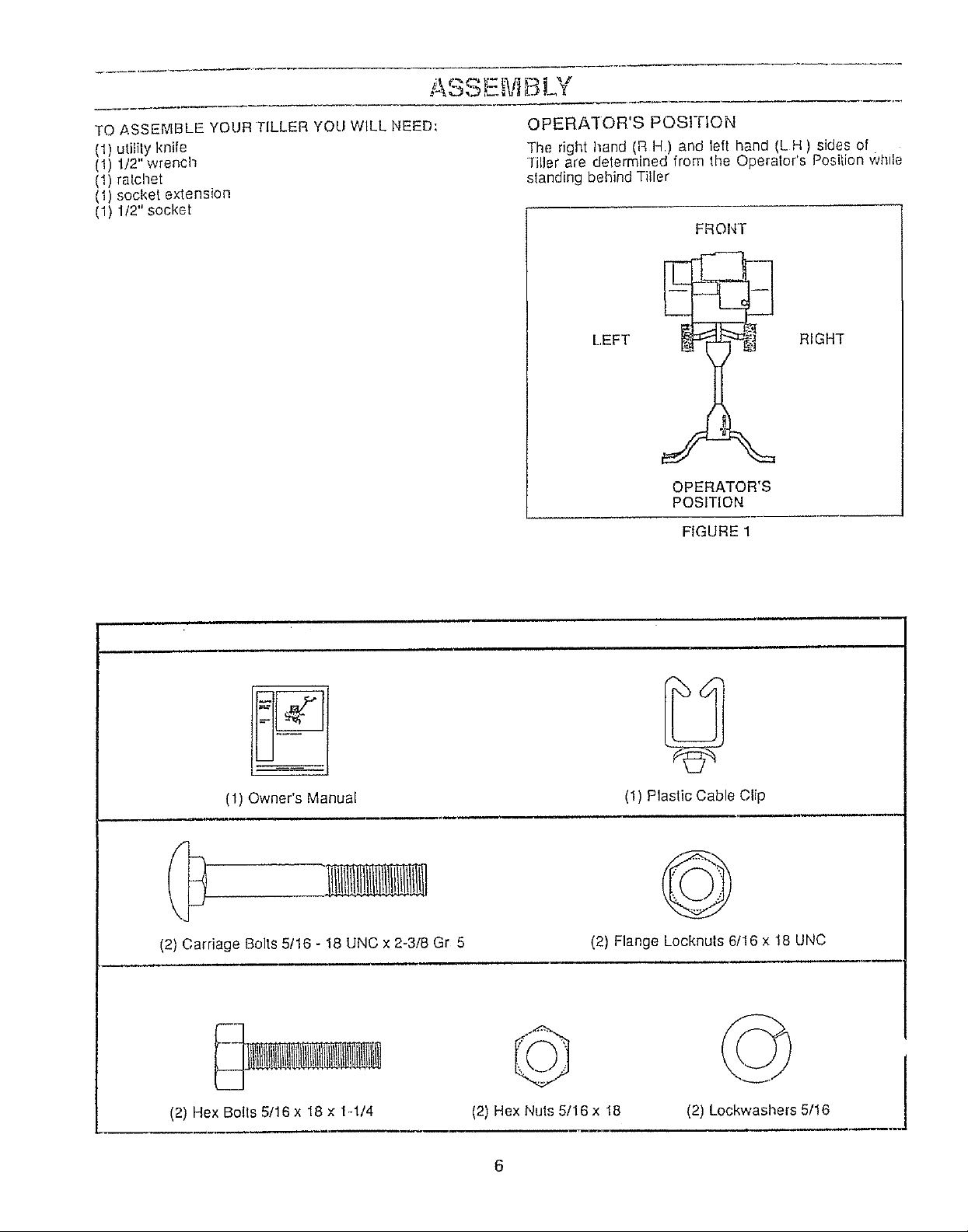
OPERATOR'S POSITION
]'he right hand (R H.) and left hand (L H ) sides of
*filler are determined from the Operelor's Position while
standing behind Tiller
FROI,,IT
LEFT RIGHT
OPERATOR'S
POSITION
FIGURE 1
(1) Owner's Manual
(2) Carriage Bolts 5!16 - 18 UNC x 2-3/8 Gr 5
(2) Hex Bolts 5/16 x 18 x 1-1/4
(2) Flange Locknuts 6/16 x 18 UNC
(2) Hex Nuts 5/16x 18
6
(1) Plastic Cable Clip
©
(2) Lockwashers 5/16
!
E,.ViBLV
UNPACK CARTON & INSTALL HANDLE
_ BE CAREFUL OF EXPOSED STAPLES
WHEN HANDLING OR DISPOSING OF
CAR'i'ONING MATERIAL°
CAUTION: Wt4EN UNPACKING AND ASSEMBLING
TILLER, BE CAREFUL NOT TO STRETCH
OR KINK CABLES
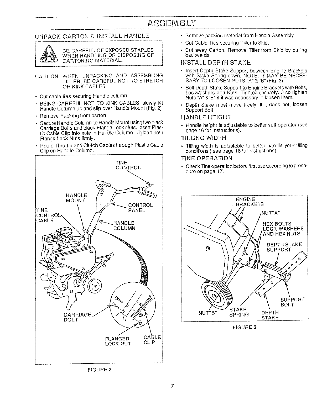
• Cut cable ties securing Handle column
• BEING CAREFUL NOT TO KINK CABLES, slowly lift
Handle Column up and slip over Handle Mounl (Fig, 2)
• Remove Packing from carton
• Secure HandleColumn to Handle Mounlusinglwoblack
Carriage Bolts and black Flange Lock Nuts, Insert Plas-
tic Cable Clip into hole in Handle Column Tighten bolh
Flange Lock Nuls limlly.
• Roule Throttle and Clulch Cables through Plastic Cable
Clip on Handle Column.
TINE
CONTROL,
• Remove packing matedal from Handle Assembly
o Cut Cable Ties securing Tiller to Skid
• Cut away Carlon Remove Tiller lrom Skid by pulling
backwards
INSTALL DEPTH S'I-AKE
• Insed Depth Slake Support beh*zeenEngine Brackets
with Stake Spring down, NOTE: IT MAY BE NECES_
SARY TO LOOSEN NUTS "A" & "B" (Fig. 3)
• Boll Depth Stake Support Io Engine Brackets with Bolls,
Lockwashers and Nuls Tighten securely. Also lighten
Nuts "A" &"B" if it was necessary fo loosen Ihem_
• Deplh Stake must move freely, If it does not, loosen
Support Bolt
HANDLE HEIGHT
• Handle height is adjustable to better suit operator (see
page 16 for instructions),
TILLING WIDTH
• Tilling width is adjuslable to beller handle your tilling
conditions ( see page 16 for instructions)
TINE OPERATION
• Check Tine operation before first useaccording to proce-
dure on page 17
HANDLE
MOUNT
CONTROL
TINE PANEL
COLUMN
CARRIAGE
BOLl"
FLANGED CABLE
LOCK NUT CLiP
ENGINE
BRACKETS
STAKE
NUT"B" SPRING
FIGURE 3
: BOLTS
SUPPORT
BOLT
DEPTH
STAKE
FIGURE 2
7
OPERATION
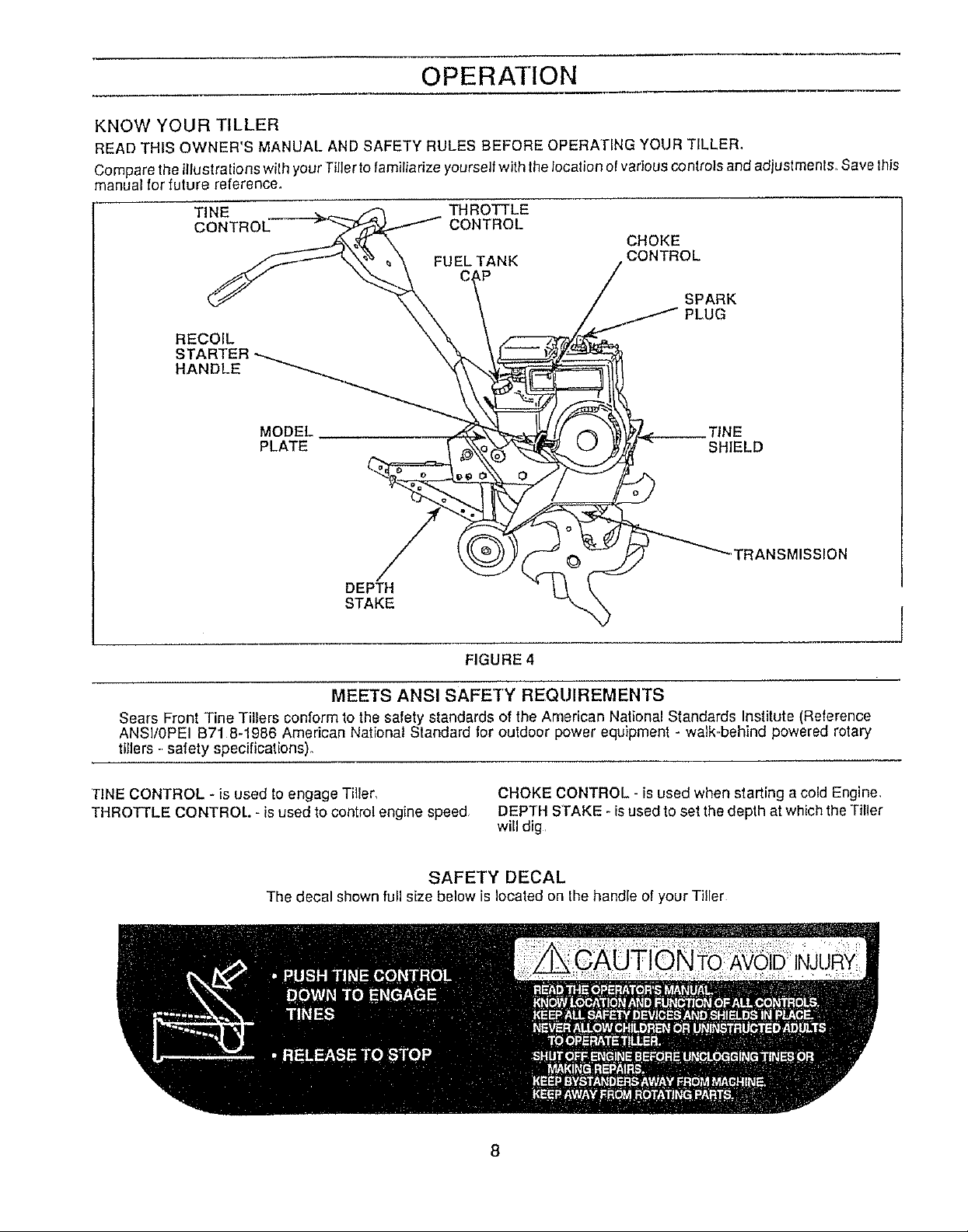
KNOW YOUR TILLER
READ THIS OWNER'S MANUAL AND SAFETY RULES BEFORE OPERATING YOUR TILLER,
Compare the illustrations with your Tiller to familiarize yourself with the location el various controls and adjustment& Save this
manual for future reference.
TINE THROTTLE
CONTROL CONTROL
FUEL TANK
RECOIL
HANDLE
MODEl. __TINE
PLATE SHIELD
CHOKE
CONTROL
SPARK
JG
""TRANSMISSION
DEPTH
STAKE I
FIGURE 4
MEETS ANSI SAFETY REQUIREMENTS
Sears Front Tine Tillers conform to lhe safety standards of the American Nalional Standards Institute (Reference
ANSI/0PEI B71 8-1986 American National Standard for outdoor power equipment - walk..behind powered rotary
tillers -safety specifications).
TINE CONTROL - is used to engage Tiller,
THROTTLE CONTROL. - is used to control engine speed
SAFETY DECAL
The decal shown full size below is Iocaled on the handle of your Tiller
CHOKE CONTROL - is used when starting a cold Engine,
DEPTH STAKE - isused to set the depth at which the Tiller
will dig
8
OPERATION
....... Fheoperalion of any Tiller can result inforeign objects thrown intotile eyes, which can result in severe
recommend Wide Vision Safely Mask for over Ihe speclacles or standard safely glasses, available at
eye damage, Always wear safety glasses or eyeshields before starting you rTiller and while lilling We
Sears Retail or Catalog Stores
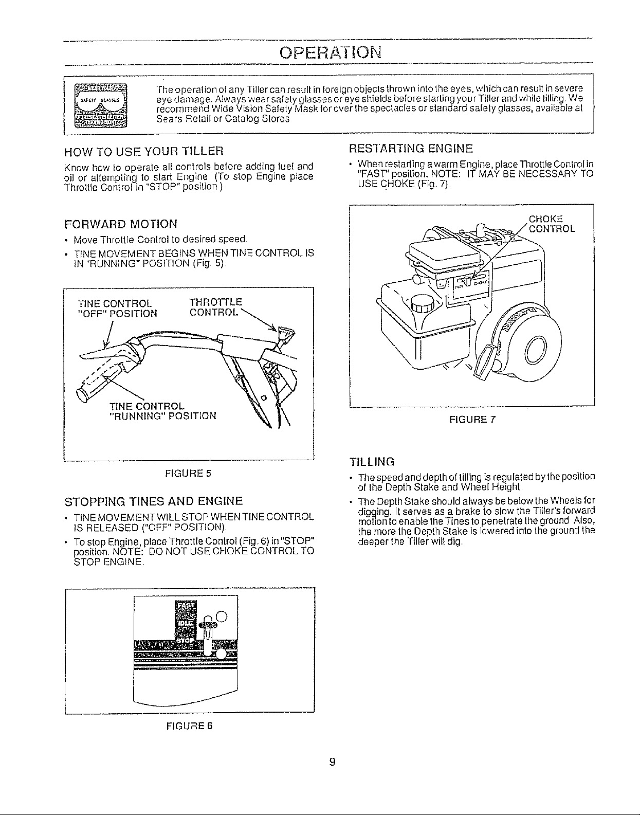
HOW TO USE YOUR TILLER
Know how Io operate all controls before adding fuel and
oil or attempting to start Engine (To stop Engine pIace
Throttle Control in "STOP" position )
FORWARD MOTION
• Move Throtlle Control to desired speed
• TINE MOVEMENT BEGINS WHEN TINE CONq-ROL IS
tN "RUNNING" POSITION (Fig 5)
TINE CONTROL
"OFF" POSITION
TINE CONTROL
"RtJNNING" POSITION
THROTTLE
CONTROL'_.4_
RESTARTING ENGINE
• When restading awarm Engine, ptace Throttle Conlrol in
"FAST" position NOTE: IT MAY BE NECESSARY TO
USE CHOKE (Fig 7)
CHOKE
ONTROL
FIGURE 7'
FIGURE 5
STOPPING TINES AND ENGINE
• TINE MOVEMENTWILL STOP WHEN TINE CONTROL
IS RELEASED ( OFF POSIT ON),
• To stop Engine, place Throttle Control (Fig, 6) in"STOP"
position, NOTE: DO NOT USE CHOKE CONTROL TO
STOP ENGINE
FIGURE 6
TILLING
• The speed and depth of tillingis regulated bythe position
of the Depth Stake and Wheel Height
• The Depth Stake should always be below theWheels for
digging, It serves as a brake to slow the Tiller's fonNard
motion toenable the Tines to penetrate theground Also,
the more the Depth Stake is lowered into the ground the
deeper the Tiller will dig
OPERATION
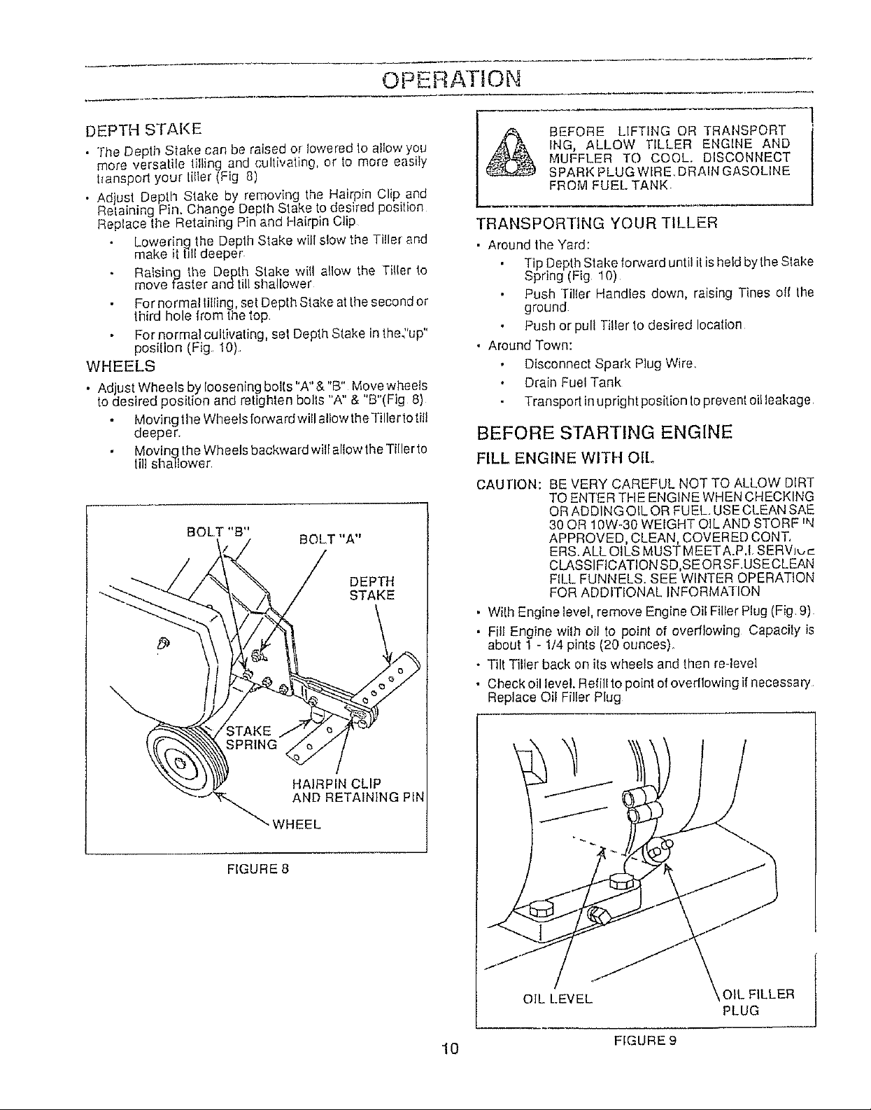
DEPTH STAKE
• "[he Dep "_Sake can be raised or lowered to allow you
more versatile lifting and cultivating, or _omore easily
hanspod your titier (Fig 8)
• Ad ust Depth Stake by removing the Hairpin Clip and
Retan ng Pin. Change Depth Stake to desired position
Replace the Retaining Pin and Hairpin Clip
Lowering the Depth Stake will slow the Tiller and
make it till deeper
Raising the Depth Stake will allow the Tiller to
move faster andtill shallower
For normal lilting, set Depth Stake at the second or
third hole from the top
For normal cultivating, set Depth Stake in the"up"
post{ion (Fig 10)
WHEELS
. Adjust Wheels by loosening bolts "A" & "B" Move wheels
to desired position and retighten bolts "A" & "B"(Fig 8)
Moving the Wheels forward will allow the Tiller'iotil!
deeper
Moving the Wheels backward will allow the Tiller to
till shallower
BOLT "B"
BOLT "A"
DEPTH
STAKE
BEFORE LIFTING OR TRANSPORT
ING, ALLOW TILLER ENGINE AND
MUFFLER TO COOL. DISCONNECT
SPAR}( PLUG WIRE, DRAIN GASOLINE
FROM FUEL TANK.
TRANSPORTING YOUR TILLER
• Around the Yard:
Tip Depth Stake forward until it ishefdby the Stake
Spring (Fig 10)
Push Ti]{er Handles down, raising Tines oil the
ground
Push or pull Tiller to desired location
• Around Town:
Disconnect Spark Plug Wire
Drain Fuel Tank
Transport in upright position to prevent of!leakage
BEFORE STARTING ENGINE
FILL ENGINE WITH OIL
CAUTION: BE VERY CAREFUL NOT TO ALLOW DIRT
TO ENTER THE ENGINE WHEN CHECKING
ORADDING OIL OR FUEL USE CLEAN SAE
30 OR 10W-30 WEIGHT OIL AND STORF rN
APPROVED, CLEAN, COVERED CONT,
ERS. ALL OILS MUST MEET A.P.! SERVJ,-,c
CLASSIFICATION SD,SE OR SF.USECLEAN
FILL FUNNELS. SEE WINTER OPERATION
FOR ADDITIONAL INFORMATION
• With Engine level, remove Engine Oil Filler Plug (Fig 9)
• Fill Engine with oil to point of ovedlowing Capacity is
about 1 - 1/4 pints (20 ounces)_
• Tilt Tiller back on its wheels and then re-level
• Check oil level. Refill to point of ovedlowing if necessary
Replace Oil Filler Plug
"WHEEL
FIGURE 8
HAIRPIN CLIP
AND RETAINING PIN
10
OIL LEVEL OIL FILLER
PLUG
FIGURE 9
J
 Loading...