

Craftsman 917297350 Owner’s Manual
,_EA/_S
OWNER'S
MANUAL
MODEL NO.
917.297350
Place Photo Here
Caution:
Read and follow
all Safety Rules
and Instructions
Before Operating
This Equipment
CRRFTXMRN°
5.0 HP
26 INCH TINE WIDTH
FRONT TINE TILLER
• Assembly
° Operation
° Customer Responsibilities
oService and Adjustments
° Repair Parts
Safe Operation Practices for Walk-Behind Powered Rotary Tillers
SAFETY RULES
TRAINING
* Read the Owner's Manual carefully. Be thoroughly
fam!Iiar with the controls and the proper use of the
equipment. Know how to stop the unit and disengage
the controls quickly°
* Never allow children to operate the equipment. Never
allow adufts to operate the equipment without proper
instruction.
• Keep the area of operation clear of all persons, particu-
larly small children, and pets.
PREPARATION
• The roughly inspect the area where the equipment is to
be used and remove all foreign objects.
• Disengage ail clutches and shift into neutral before
starting the engine (motor).
• Do not operate the equipment without wearing ad-
equate outer garrnents_ Wear footwear that will im-
prove footing on slippery surfaces,
• Handle fuel with care; it is highly flammable_
• Use an approved fuel container.
• NevJ add fuel to a running engine or hot engine.
° Fill fuel tank outdoors with extreme care. Never fill
fuel tank indoors.
• Replace gasoline cap securely and clean up spilled
fuel before restarting.
• Use extension cords and receptacles as specified by
the manufacturer for all units with electric drive motors
or eiectdc starting motors.
• Never attempt to make any adjustments while the
engine (motor) is running (except where specifically
recommended by manufacturer).
OPERATION
• Do not put hands or feet near or under rotating parts.
o Exercise extreme caution when operating on or cress-
mg gravel drives, walks, or roads. Stay alert for hidden
hazards or traffic. Do not carry passengers.
° After striking a foreign object, stop the engine (motor),
remove the wire from the spark plug, thoroughly in-
spect the tiller for any damage, and repair the damage
before restarting and operating the tiller°
• Exercise caution to avoid slipping or falling.
• If the unit should start to vibrate abnormally, stop the
engine (motor) and check immediately for the cause.
Vibration is generally a warning of trouble.
• Stop the engine (motor) when leaving the operating
position.
• Take all possible precautions when Ieaving the ma-
chine unattended. Disengage the tines, shift into
neutral, and stop the engine.
• Before cleaning, repairing, or inspecting shut off the
eng ne and make certain all moving parts have stopped.
Disconnect the spark plug wire, and keep the wire
away from the plug to prevent accidental starting.
Disconnect the cord on electric motors.
• Donot run the engine indoors; exhaust fumes are
dangerous.
• Never operate the tiller' without proper guards, plates,
or other safety protective devices in place.
• Keep children and pets away.
• Do not overload the machine capacity by attempting to
till too deep at too fast a rate°
• Never operate the machirTe at high speeds on slippery
surfaces. Look behind an# use care when backing_
° Never allow bystanders near the unit.
• Use only attachments and accessories approved by
the manufacturer of the tilIer (such as wheat weights,
counterweights, cabs, and the like).
- Never operate the tiller without good visibility or light.
• Be careful when tilling in hard ground_ The tines may
catch in the ground and propel the tiller forward, tf this
occurs, let go of the handlebars and do not restrain the
machine.
MAINTENANCE AND STORAGE
• Keep machine, attachments, and accessories in safe
workingcondition.
• Check shear pins, engine mounting bolts, and other
bolts at frequent intervals for proper tightness to be
sure the equipment is in safe working condition.
o Never store the machine with fuel in the fuel tank inside
a building where ignition sources are present, such as
hot water and space heaters, clothes dryers, and the
like. A_low the engine to cool before storing in any
enctosure_
• Always refer to the operator's guide instructions for
important details if the tiller is to be stored for an
extended period.
- IMPORTANT -
CAUTIONS, tMPORTANTS, AND NOTES ARE A MEANS OF A'i-t'RACTING ATTENTION TO IMPO RTANT OR CRITICAL
INFORMATION IN "THIS MANUAL.
CAUTION: Look for this symbol to point
out important safety precautions. It
means--Attention! Become Alert! Your
safety is involved.
IMPORTANT: USED TO ALERT YOU THAT THERE tS A
POSSIBILITY OF DAMAGING THIS EQUIPMENT.
NOTE: Gives essential information that wi]l aid you to better
understand, incorporate, or execute a particular set of instruc-
tions.
CONGRATULATIONS on your purchase of a Sears Tiller.
It has been designed, engineered and manufactured to
t_ive yoL the best possible dependability and performance.
Should you experience any problems you cannot easily
remedy, piease contact your nearest authorized Sears
Service Center/Department. They have competent, well-
trained technicians and the proper tools to service or repair
this unit.
Please read and retain this manual. The instructions witl
enable you to assemble and maintain your tiller properly.
Always observe the "SAFETY RULES",
MODEL
NUMBER 917,297350
SERIAL
NUMBER
DATE OF
PURCHASE
THE MODEL AND SERIAL NUMBERS WILL BE
FOUND ON THE MODEL PLATE ATTACHED TO
THE RIGHT HAND ENGINE BRACKET°
YOU SHOULD RECORD BOTH SERtAL NUMBER
AND DATE OF PURCHASE AND KEEP IN A SAFE
PLACE FOR FUTURE REFERENCE.
PRODUCT SPECIFICATIONS
HORSEPOWER: 5.0 HP
DISPLACEMENT: 12..57 cu. in.
GASOLINE CAPACITY: 3 Quarts
Unleaded Regular
OIL (API-SG): SAE 30W (Above 32°F)
(CAPACITY: 20 oz.. [0..6L]) SAE 5W-30 (Betow 32°F)
SPARK PLUG : Champion
(GAP: _030" [076mini) RJ19LM (STD361458)
MAINTENANCE AGREEMENT
A Sears Maintenance Agreement is available on this prod-
ucto Contact your nearest Sears store for details.
CUSTOMER RESPONSIBILITIES
* Read and observe the safety rules,,
- Fo!Iow a regular schedule in maintaining, cadng for and
using your tilter.
- Follow the instructions under "Customer
Responsibilities" and "Storage" sections of this Owner's
Manual
IMPORTANT: THIS UNIT 1S EQUIPPED WITH AN INTERNAL COMBUSTION ENGINE AND SHOULD NOT BE USED ON
OR NEAR ANY UNIMPROVED FOREST-COVERED, BRUSH-COVERED OR GRASS COVERED LAND UNLESS THE
ENGINE'S EXHAUST SYSTEM IS EQUIPPED WITH. A SPARK ARRESTER MEETING APPLICABLE LOCAL OR STATE
LAWS (IF ANY). IFA SPARKARRESTER IS USED, IT SHOULD BE MAINTAINED IN EFFECTIVE WORKING ORDER BY
THE OPERATOR.
IN THE STATE OF CALIFORNIA THE ABOVE IS REQUIRED BY LAW (SECTION 4442 OF THE CALIFORNIA PUBLIC
RESOURCES CODE). OTHER STATES MAY HAVE SIMILAR LAWS. FEDERAL LAWS APPLY ON FEDERAL LANDS.
SEE YOUR SEARS AUTHORIZED SERVICE CENTER/DEPARTMENT FOR SPARK ARRESTER. REFER TO THE REPAIR
PARTS SECTION OF THIS MANUAL FOR PART NUMBER.
LIMITED TWO YEAR WARRANTY ON CRAFTSMAN TILLER
For two (2) years from date of purchase, when this Craftsman Tiller is maintained, lubricated, and tuned up
according to the operating and maintenance instructions in the owner's manual, Sears will repair free of charge any
defect in material or workmanship.
This Warranty does not cover:.
° Expendable items which become worn during normal use, such as tines, spark plugs, air cleaners and belts.
o Repairs necessary because of operator abuse or negligence, including bent crankshafts and the failure to
maintain the equipment according to the instructions contained in the owner's manual
• If this Craftsman Tiller is used for commercial or rental purposes, this Warranty applies for only thirty (30) days
from the date of purchase.
WARRANTY SERVICE IS AVAILABLE BY RETURNING THE CRAFTSMAN TILLER TO THE NEAREST SEARS
SERVICE CENTEPJDEPARTMENT IN THE UNITED STATES. THIS WARRANTY APPLIES ONLY WHILE THIS
PRODUCT 1S IN USE IN THE UNITED STATES.
This Warranty gives you specific legal rights, and you may also have other rights which vary from state to state.
SEARS, ROEBUCK AND COo, D/817 WA, HOFFMAN ESTATES, IL 60179
TABLE OF CONTENTS
,,,,=JH,=,,,,n i ,, ,,, , ii,=l i=l i
SAFETY RULES ........................................................... 2
CUSTOMER RESPONSIBILITIES ..................... 3, 12-14
PRODUCT SPECIFICATIONS ....................................... 3
WARRANTY ................................................................... 3
ACCESSORIES ............................................................. 5
ASSEMBLY ................................................................ 6-7
OPERATION ............................................................. 8-11
INDEX
A
Accessories ...........................................5
Adjustments:
Carburetor ............................... 17
Depth Stake ............................... 9
Handle Height .......................... 14
Tines ................................... 14-15
V-Belt ......................................... 16
Wheels ......................................... 9
Air Cleaner ...................................... 13
B
Belt, V-:
Belt Guard ........................ :...... 17
Repair Parts ............................. 21
V-Belt Replacement ........... _..... 16
C
Cooling System .............................. 13
Controls:
Choke ........................................ 8
Throttle ...................................... 8
Tines .......................................... 8
Cultivating ...................................... 11
Customer Responsibilities:
Air Cleaner ............................... 13
Cooling System ....................... 13
Finish ....................................... 14
Maintenance Schedule ............ 12
Muffler ...................................... 14
Oil Change ................................ 13
Spark Ptug ............................... 14
Transmission ........................... t4
D
Depth Stake:
Adjustment ................................. 9
Repair Parts ............................. 22
E
Engine:
Air Cleaner ................................ 13
Cooling System ....................... 13
Fuel Type ................................. 10
Lubrication ............................... 13
Oil Level ................................... 10
Oil Type ...................................t0,13
Repair Parts .......................... 26-30
Spark Plug ................................. 14
Starting ...................................... 10
Stopping ...................................... 9
Storage .................................... 18
Winter Operation ..................... 13
Fuel:
Filling Tank ................................. 10,
Storage ..................................... 18
Type ............................................. 10"
Finish:
Maintenance ............................. 14
Handle:
Height Adjustment .................... 14
Repair Parts ............................. 20
Lubrication:
Lubrication Chart .................... 12
Engine ...................................... 13
Muffler:
Maintenance ............................ 14
Spark Arrester ........................... 3
Oil:
Leve! ........................................ 10
Type .................................... 10,13
Operation:
Cultivating ................................ 1t
Fill Fuel _lank ........................... 10
Starting Engine ........................ 10
Stopping Tines & Engine ........... 9
Tilling ......................................... 9
Tilling Hints .............................. 11
line Operation ........................... g
Transporting Tiller .................... 10
Winter Operation ..................... 13
MAINTENANCE SCHEDULE ...................................... 12
SERVICE & ADJUSTMENTS ................................. 14-17
STORAGE .................................................................... 18
TROUBLESHOOTING ................................................. 19
REPAIR PARTS-TILLER ........................................ 20-25
REPAIR PARTS-ENGINE ....................................... 26-30
SERVICE/PARTS ORDERING .................... Back Cover
R
Repair Parts
Tiller ....................................... 20-24
Engine ................................ 26-30
Rules for Safe Operation ......................2
S
F
H
L
M
O
Service & Adjustments:
Carburetor ................................ 17
Handle Height ........................... 14
Tines ...................................... 14-15
V-Belt ......................................... 16
Wheels ...................................................9
Service:
Repair Parts ........................ 20-30
Service Record ......................... 12
Spark Plug:
Gap ............................................. 3
Maintenance ............................ 14
Storage:
Fuel System ............................. 18
Tiller ......................................... 18
T
Tilling ............................................... 9,11
Tines:
Arrangement ........................ 14-15
Operation ................................... 9
Repair Parts .............................. 23
Replacement .............................. 15
Transmission:
Maintenance .............................. 14
Repair Parts .............................. 24
Troubleshooting ................................ 19
Transporting ................................... 10
W
Warranty ........................................... 3
Wheels:
Adjustments ............................... 9
Repair Parts ............................. 22
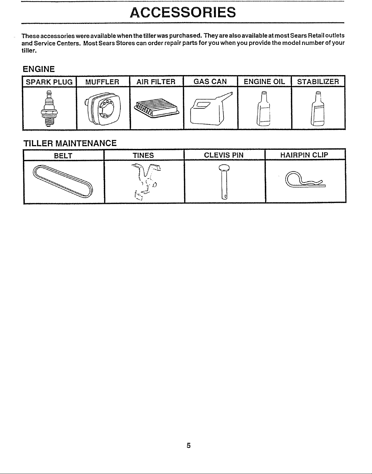
These accessories were available when the tiller was purchased. They are also available at most Sears Retail outlets
and Service Centers. Most Sears Stores can order repair parts for you when you provide the model number ofyour
tiller.
ENGINE
SPARK PLUG MUFFLER
TILLER MAINTENANCE
BELT
ii i ii
AIR FILTER GAS CAN ENGINE OIL STABILIZER
TINES
CLEVIS PIN
,,,,,,,,,,,,,,,,,,,,,,,,,,,,,,,,,,,
HAIRPIN CLIP
0
t:.r->
5
ASSEMBLY
i i,i i ii,ll ,i,illl i lllllll , ill l i ii i i i,,,u,ill,,i,, ,lllllll
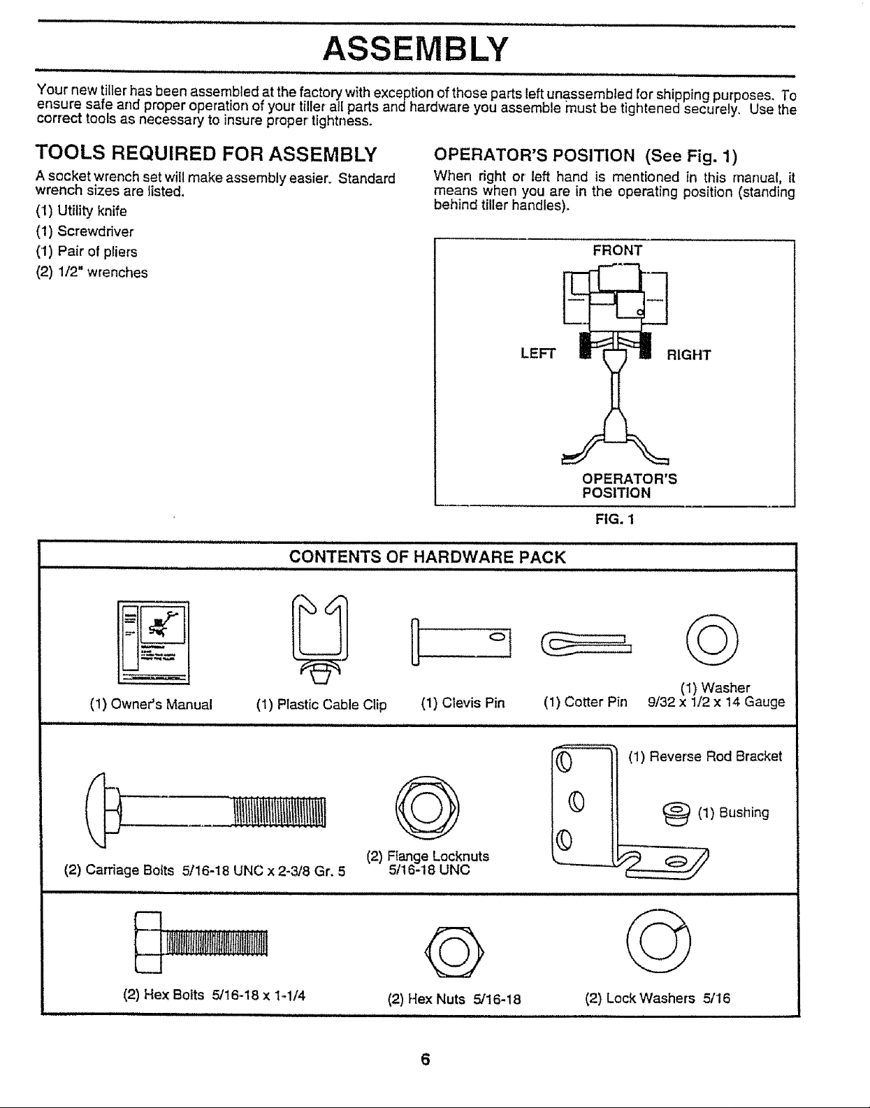
Your new tiller has been assembled at the factory with exception of those parts left unassembled for shipping purposes. To
ensure safe and proper operation of your tiller all parts and hardware you assemble must be tightened securely, Use the
correct tools as necessary to insure proper' tightness.
TOOLS REQUIRED FOR ASSEMBLY
A socket wrench set will make assembly easier. Standard
wrench sizes are listed,
(1) Utility knife
(1) Screwdriver
(1) Pair of pliers
(2) 1/2" wrenches
CONTENTS OF HARDWARE PACK
OPERATOR'S POSITION (See Fig. 1)
When dght or left hand is mentioned in this manual, it
means when you are in the operating position (standing
behind tiller handles).
FRONT
LEFT
OPERATOR'S
POSITION
FIG. 1
IGHT
(1) Owner's Manual (1) Plastic Cable Clip (1) Clevis Pin
Q
(2) F{ange Locknuts
(2) Carriage Bolts 5/16-18 UNC x 2-3/8 Gr. 5
i,,i Niiiiillllllllll ii
i!iti { jJil,imiitisi!tnria {li J!
(2) Hex Bolts 5/16-18 x 1,-t/4
5/16-18 UNC
Q
(2) Hex Nuts 5/16-18
I,IHI lll l
(1) Cotter Pin
©
(1) Reverse Rod Bracket
©
©
(2) Lock Washers 5/16
©
(1) Washer
9/32 x 1/2 x 14 Gauge
(_(1) Bushing
6
UNPACKCARTON
ASSEMBLY
! _ CAUTION: Be careful of exposed
ii ,,H,IH H III
cartoning material.
IMPORTANT: WHEN UNPACKING AND ASSEMBLING
TILLER, BE CAREFUL NOT TO STRETCH OR KINK
CABLE(S).,
- Cut cable ties securing handle column°
o Slowly lift handle column and iay it over tiller°
. " Remove packing from carton. Hardware pack isfound
in folded cardboard packing.
= S!]de handle cotumn onto handle mount,.
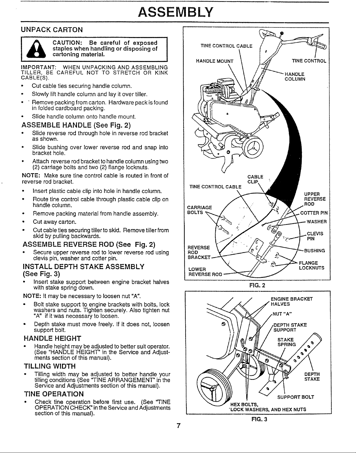
ASSEMBLE HANDLE (See Fig. 2)
staples when handling or disposing of
= Slide reverse rod through hote in reverse rod bracket
as shown.
• Slide bushing over lower reverse rod and snap into
bracket hole.
• Attach reverse rod bracket to handle column using two
(2) carriage bolts and two (2) flange tocknuts.
NOTE: Make sure tine control cable is routed in front of
reverse rod bracket.
• Insert plastic cable clip into hole in handle column.
• Route tine control cable through plastic cable clip on
handle column,
• Remove packing material from handle assembly.
• Cut away carton.
o Cut cable ties securing tiller to skid. Remove tiller from
skid by pulling backwards.
ASSEMBLE REVERSE ROD (See Fig. 2)
o Secure upper reverse rod to lower reverse rod using
clevis pin, washer and cotter pin.
INSTALL DEPTH STAKE ASSEMBLY
(See Fig. 3)
• Insert stake support between engine bracket halves
with stake spring down,
NOTE: It may be necessary to loosen nut "A"°
• Bolt stake support to engine brackets with bolts, {ock
washers and nuts. Tighten securely. Also tighten nut
"A" if itwas necessary to loosen.
° Depth stake must move freely, if it does not, loosen
support bolt.
HANDLE HEIGHT
TINECONTROLCABLE
HANDLE MOUNT
TINE CONTROL CABLE
CARRIAGE
BOLTS
REVERSE
ROD
LOWER
REVERSEROC
TINE CONTROL
COLUMN
CABLE
UPPER
REVERSE
ROD
CLEVIS
PIN
FLANGE
LOCKNUTS
FIG. 2
ENGINE BRACKET
_LVES
DEPTH STAKE
IUPPORT
• Handle height may be adjusted to better suit operator.
(See HANDLE HEIGHT" in the Service and Adjust-
ments section of this manual).
TILLING WIDTH
• Tilling width may be adjusted to better handle your
tilting conditions (See "FINE ARRANGEMENT" in the
Service and Adjustments section of this manual).
TINE OPERATION
• Check tine operation before first use. (See "TINE
OPERATION CHECK" inthe Service and Adjustments
section of this manual).
DEPTH
STAKE
SUPPORT BOLT
HEXBGLTS,
'LOCK WASHERS, AND HEX NUTS
RG. 3
OPERATION
,,,,,, ,,,Hi, i,,,, i , ,,,,,,,,,,,i,,, J, , ,i ................... ,,,,,,,,,,,,,,,,,,,,,, ,,,,
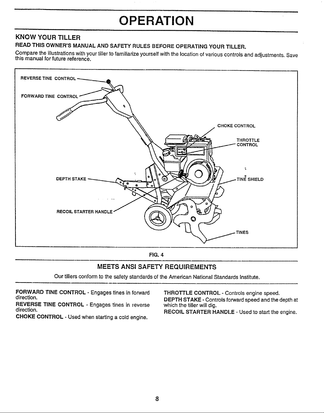
KNOW YOUR TILLER
READ THIS OWNER'S MANUAL AND SAFETY RULES BEFORE OPERATING YOUR TILLER.
Compare the illustrations with your tiIler to familiarize yourself with the location of various controls and adjustments° Save
this manual for future reference.
FORWARD 33NE CONTROL
CHOKE CONTROL
THROTTLE
DEPTH STAKE
RECOILSTARTERHANDLE
MEETS ANSI SAFETY REQUIREMENTS
Our tillers conform to the safety standards of the American National Standards Institute.
FORWARD TINE CONTROL - Engages tines in forward
direction.
REVERSE TINE CONTROL - Engages tines in reverse
direction.
CHOKE CONTROL - Used when starting a cold engine.
O
FIG. 4
THROTTLE CONTROL- Controls engine speed.
DEPTH STAKE - Controls forward speed and the depth at
which the tiller will dig.
RECOIL STARTER HANDt.E - Used to start the engine.
OPERATIO
The operation of any tiller can result in foreign objects thrown into the eyes, which can
result in severe eye damage. Always wear safety glasses or eye shields before starting
your tiller and while tilling. We recommend a wide vision safety mask for over the spec-
tacles or standard safety glasses.
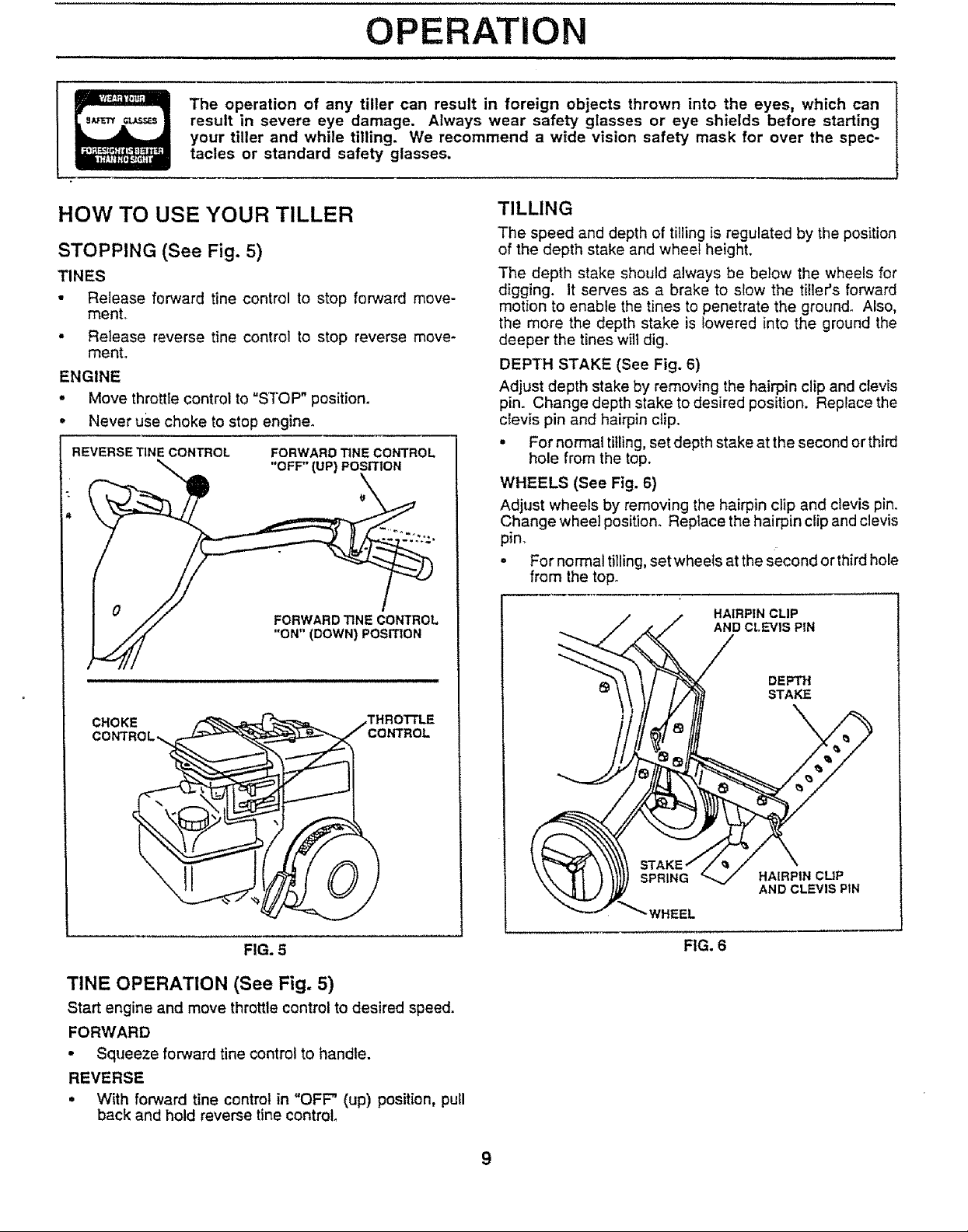
HOW TO USE YOUR TILLER
STOPPING (See Fig. 5)
TINES
• Release forward tine control to stop forward move-
menL
• Release reverse tine control to stop reverse move-
ment.
ENGINE
- Move throttle control to "STOP" position.
- Never use choke to stop engine.
REVERSE TINE CONTROL FORWARD TINE CONTROL
\-_ "OFF" (UP) POSITION
__,L
,_ "ON" (DOWN) POSITION
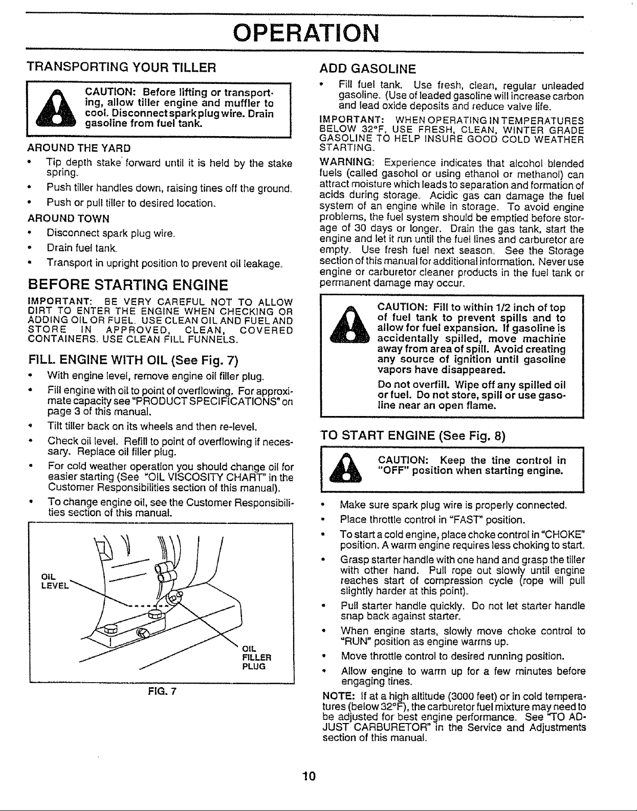
TILLING
The speed and depth of tilling is regulated by the position
of the depth stake and wheel height.
The depth stake should always be below the wheels for
digging. It serves as a brake to slow the tiller's forward
motion to enable the tines to penetrate the ground, Also,
the more the depth stake is lowered into the ground the
deeper the tines will dig°
DEPTH STAKE (See Fig. 6)
Adjust depth stake by removing the hairpin clip and clevis
pin. Change depth stake to desired position. Replace the
clevis pin and hairpin clip.
• For normal tilling, set depth stake at the second or third
hole from the top.
WHEELS (See Fig. 6)
Adjust wheels by removing the hairpin clip and clevis pin.
Change wheel position. Replace the hairpin clip and clevis
pin.
• For normal tilling, set wheels at the second or third hole
from the top_
HAIRPIN CLIP
AND CLEVIS PIN
DEPT_{
STAKE
CHOKE ,THROTTLE
FIG. 5
T1NE OPERATION (See Fig. 5)
Start engine and move throttle control to desired speed.
FORWARD
• Squeeze forward tine control to handle.
REVERSE
• With forward tine control in =OFF" (up) position, pull
back and hold reverse tine control.
SPRING
_"WHEEL
HAIRPIN CLIP
AND CLEVIS PiN
FIG. 6
,lull, ,,i i
OPERATION
TRANSPORTING YOUR TILLER
ILi,ii , ,i illllll i
CAUTION: Before lifting or transport.
ing, allow tiller engine and muffler to
cool. Disconnect spark plug wire. Drain
gasoline from fuel tank.
AROUND THE YARD
• Tip depth stake forward until it is held by the stake
spring°
• Push tiller handles down, raising tines off the ground.
- Push or pull tiller to desired Iocation_
AROUND TOWN
• Disconnect spark plug wire,
• Drain fuet tank°
• Transport in upright position to prevent oil leakage.
BEFORE STARTING ENGINE
iMPORTANT: BE VERY CAREFUL NOT TO ALLOW
DIRT TO ENTER THE ENGINE WHEN CHECKING OR
ADDING OILOR FUEL. USE CLEAN OIL AND FUEL AND
STORE IN APPROVED, CLEAN, COVERED
CONTAINERS. USE CLEAN FILL FUNNELS.
FILL. ENGINE WITH OIL (See Fig. 7)
• With engine level, remove engine oil filler plug.
• Fitl engine with oil to point of overflowing. For approxi-
mate capacity see "PRODUCT SPECIFICATIONS" on
page 3 of this manual.
• Tilt tiller back on its wheels and then re-leveL
• Check oil level. Refill to point of overflowing if neces-
sary. Replace oil filler plug.
• For cold weather operation you should change oil for
easier starting (See OIL VISCOSITY CHART" in the
Customer Responsibilities section of this manual).
• To change engine oil, see the Customer Responsibili-
ties section of this manual.
OIL
OIL
FILLER
PLUG
FIG. 7
ADD GASOLINE
• Fill fuel tank. Use fresh, clean, regular unleaded
gasoline. (Use of leaded gasoline will increase carbon
and lead oxide deposits and reduce valve life.
iMPORTANT: WHEN OPERATING IN TEMPERATURES
BELOW 32°F, USE FRESH, CLEAN, WINTER GRADE
GASOLINE TO HELP INSURE GOOD COLD WEATHER
STARTING
WARNING: Experience indicates that atcohol blended
fuels (called gasohol or using ethanol or methanol) can
attract moisture which leads to separation and formation of
acids during storage. Acidic gas can damage the fuel
system of an engine while in storage. To avoid engine
problems, the fuel system should be emptied before stor-
age of 30 days or longer, Drain the gas tank, start the
engine and let it run until the fuel lines and carburetor are
empty. Use fresh fuel next season° See the Storage
section of thismanual for additional inforrnation. Never use
engine or carburetor cleaner products in the fuel tank or'
lermanent damage may occur.
of fuel tank to prevent spills and to
allow for fuel expansion, if gasoline is
CAUTION: Fill to within 112 inch of top
accidentally spilled, move machin'e
away from area of spill. Avoid creating
any source of ignition until gasoline
vapors have disappeared.
Do not overfill. Wipe off any spilled oil
or fuel. Do not store, spill or use gaso-
line near an open flame.
HHHH, nHH, '1 I
TO START ENGINE (See Fig. 8)
I ...... CAUTION:'"'""Keep the tine control in I
&
i "OFF" position when starting engine.
• Make sure spark plug wire is properly connected.
• Place throttle control in "FAST" position.
• To start a cold engine, place choke control in"CHOKE"
position. A warm engine requires less choking to start.
• Grasp starter handle with one hand and grasp the tiller
with other hand. Pull rope out slowly until engine
reaches start of compression cycle (rope will pull
sfightly harder at this point).
• Pull starter handle quickly. Do not let starter' handle
snap back against starter°
• When engine starts, slowly move choke control to
=RUN" position as engine warms up.
• Move throttle control to desired running position.
• Allow engine to warm up for a few minutes before
engaging tines_
NOTE: If at a high altitude (3000 feet) or in co_d tempera-
lures (below 32°F), the carburetor fuel mixture may need to
be adjusted for best engine performance° See "TO AD-
JUST CARBURETOR" in the Service and Adjustments
section of this manual.
I
10
 Loading...