

Page 1

Operator's Manual
(RRFT$1ViRN°
GAR TRACTO
26.0 HR* 54" Mower
Electric Start
6 Speed Transaxle
Model No.
917.28945
, Espaflol, p. 36
This product has a low emission engine which operates
differently from previously built engines. Before you start the
engine, read and understand this Owner's Manual.
IMPORTANT:
Read and follow all Safety
Rules and Instructions before
operating this equipment.
SEARS, ROEBUCK AND COo, HOFFMAN ESTATES, IL 60179 U.S.A.
Visit our Craftsman website:www_sears.com/craftsman *As rated by the engine manufacturer
For answers to your questions
about this product, Call:
1-800 =659-5917
Sears CraftsmanHelp Line
5 am - 5 pm, Mon - Sat
426114 Rev. 1
Page 2

Warranty .................................................. 2
Safety Rules ............................................ 3
Product Specifications ................................... 6
Assembly/Pre-Operation ......................... 8
Operation ............................................... 13
Maintenance Schedule .......................... 20
CRAFTSMAN FULL WARRANTY
TWO YEARS ON RIDING EQUIPMENT
When operated and maintained according to all supplied instructions, if this riding equipment
fails due to a defect in material or workmanship within two years from the date or purchase,
call 1-800-4-MY-HOME® to arrange for free repair.
Also, when operated and maintained according to all supplied instructions, Warranty will
also cover defects in material and workmanship of the Frame and Front Axle for five years
from the date of purchase
Maintenance .......................................... 20
Service and Adjustments ....................... 25
Storage .................................................. 30
Troubleshooting ..................................... 31
Sears Service ........................... Back Cover
This warranty covers ONLY defects in material and workmanship. Sears will NOT
pay for:
. Expendable items that become worn during normal use, including but not limited to
blades, spark plugs, air cleaners, belts, and oil filters.
° Standard maintenance servicing, oil changes, or tune-ups.
° Tire replacement or repair caused by punctures from outside objects, such as nails,
thorns, stumps, or glass.
- Tire or wheel replacement or repair resulting from normal wear, accident, or improper
operation or maintenance.
• Repairs necessary because of operator abuse, including but not limited to damage
caused by towing objects beyond the capability of the riding equipment, impacting
objects that bend the frame or crankshaft, or over-speeding the engine.
° Repairs necessary because of operator negligence, including but not limited to, electrical
and mechanical damage caused by improper storage, failure to use the proper grade
and amount of engine oil, failure to keep the deck clear of flammable debris, or failure to
maintain the riding equipment according to the instructions contained in the operator's
manual.
• Engine (fuel system) cleaning or repairs caused by fuel determined to be contaminated or
oxidized (stale). In general, fuel should be used within 30 days of its purchase date.
- Normal deterioration and wear of the exterior finishes, or product label replacement.
All riding equipment and batter,.# warranty coverage is void if this product is ever used for
commercial or rental purposes.
This warranty applies only while this product is within the United States.
This warranty gives you specific legal rights, and you may also have other rights which
vary from state to state,
Sears, Roebuck and Co., Hoffman Estates, IL 60179
2
Page 3
_IbDANGER:This cutting machine is capable of amputating hands and feet and
throwing objects. Failure to observe the following safety instructions could result
in serious injury or death,
_WARNING" In order to prevent acciden-
tal starting when setting up, transporting,
adjusting or making repairs, always discon-
nect spark plug wire and place wire where
it cannot contact spark plug.
_WARNING: Do not coast down a hill in
neutral, you may lose control of the tractor.
,_WARNING: Tow only the attachments
that are recommended by and comply with
specifications of the manufacturer of your
tractor. Use common sense when towing.
Operate only at the lowest possible speed
when on a slope. Too heavy of a toad, while
on a slope, is dangerous. Tires can lose
traction with the ground and cause you to
lose control of your tractor.
,_WARNING: Engine exhaust, some of
its constituents, and certain vehicle compo-
nents contain or emit chemicals known to the
State of California to cause cancer and birth
defects or other reproductive harm.
_IbWARNING: Battery posts, terminals and
related accessories contain lead and lead
compounds, chemicals known to the State of
California to cause cancer and birth defects
or other reproductive harm, Wash hands
after handling.
I. GENERAL OPERATION
• Read, understand, and follow all instruc-
tions on the machine and in the manual
before starting.
• Do not put hands or feet near rotating
parts or under the machine. Keep clear
of the discharge opening at all times.
• Only allow responsible adults, who are
familiar with the instructions, to operate
the machine.
• Clear the area of objects such as rocks,
toys, wire, etc., which could be picked
up and thrown by the blades°
• Be sure the area is clear of bystanders
before operating. Stop machine ifanyone
enters the area.
• Never carry passengers_
• Do not mow in reverse unless absolutely
necessary_ Always look down and behind
before and while backing°
° Never direct discharged materialtoward
anyone. Avoid discharging material
against a wall or obstruction. Material
may ricochet back toward the operator.
Stop the blades when crossing gravel
surfaces.
• Do not operate machine without the en-
tire grass catcher, discharge chute, or
other safety devices in place and working.
• Slow down before turning.
• Never leave a running machine unat-
tended. Always turn off blades, set
parking brake, stop engine, and remove
keys before dismounting.
• Disengage blades when not mowing.
Shut off engine and wait for all parts to
come to a complete stop before cleaning
the machine, removing the grass catcher,
or unclogging the discharge chute.
• Operate machine onlyin daylightorgood
artificial light.
• Do not operatethe machine while under
the influence of alcohol or drugs.
, Watch for traffic when operating near or
crossing roadways_
• Use extracarewhen Ioadingor unloading
the machine into a trailer or truck.
. Always wear eye protectionwhen operat-
ing machine.
° Data indicates that operators, age 60
years and above, are involved in a large
percentage of riding mower-related inju=
ries. These operators should evaluate
their ability to operate the riding mower
safely enough to protect themselves and
others from serious injury.
• Follow the manufacturer's recommen-
dation for wheel weights or counter-
weights.
• Keep machine free of grass, leaves or
other debris build-up which can touch hot
exhaust / engine parts and burn. Do not
allow the mower to plow leaves or other
debris which can cause build-up to oc-
cur. Clean any oil or fuel spillage before
operating or storing the machine. Allow
machine to cool before storage.
3
Page 4
!1. SLOPE OPERATION
Slopes are a major factor related to loss of
control and tip-over accidents, which can
result in severe injury or death. Operation
on all slopes requires extra caution. If you
cannot back up the slope or ifyou feel uneasy
on it, do not mow it.
• Mow up and down slopes, not across.
• Watch for holes, ruts, bumps, rocks, or
other hidden objects. Uneven terrain
could overturn the machine. Tail grass
can hide obstacles.
° Choose a low ground speed so that you
will not have to stop or shift while on the
slope.
• Do not mow on wet grass, Tires may lose
traction.
Always keep the machine in gear when
going down slopes. Do not shift to neutral
and coast downhill.
, Avoid starting, stopping, or turning on a
slope, tfthe tires Iosetraction, disengage
the blades and proceed slowly straight
down the slope.
° Keep all movement on the slopes slow
and gradual. Do not make sudden
changes in speed or direction, which
could cause the machine to roll over.
° Use extra care while operating machine
with grass catchers or other attachments;
they can affect the stability of the ma-
chine. Do no use on steep slopes.
° Do not try to stabilize the machine by
putting your foot on the ground.
, Do not mow near drop-offs, ditches,
or embankments. The machine could
suddenly roll over if a wheel is over the
edge or if the edge caves in.
!11,CHILDREN
Tragic accidents can occur if the operator
is not alert to the presence of children.
Children are often attracted to the machine
and the mowing activity. Never assume
that children will remain where you last
saw them.
• Keep children out of the mowing area
and in the watchful care of a responsible
adult other than the operator.
• Be alert and turn machine off if a child
enters the area.
• Before and while backing, look behind
and down for small children.
• Never carry children, even with the
blades shut off° They may fall off and
be seriously injured or interfere with safe
machine operation, Children who have
been given rides in the past may suddenly
appear in the mowing area for another
ride and be run over or backed over by
the machine.
. Never allow children to operate the ma-
chine.
, Use extra care when approaching blind
corners, shrubs, trees, or other objects
that may block your view of a child.
IV, TOWING
° Tow only with a machine that has a hitch
designed for towing. Do not attach towed
equipment except at the hitch point.
° Followthemanufacturer'srecommenda-
tion for weight limits for towed equipment
and towing on slopes,
° Never allow children or others in or on
towed equipment.
. On slopes,the weight of the towed equip-
ment may cause loss of traction and loss
of control,
. Travel slowly and allow extra distance to
stop.
V. SERVICE
SAFE HANDLING OF GASOLINE
To avoid personal injury or property dam-
age, use extreme care in handling gasoline.
Gasoline is extremely flammable and the
vapors are explosive.
• Extinguish all cigarettes, cigars, pipes,
and other sources of ignition.
- Use only approved gasoline container.
• Never remove gas cap or add fuel with
the engine running. Allow engine to cool
before refueling.
, Never fuelthe machine indoors.
• Never store the machine or fuel container
where there is an open flame, spark, or
pilot light such as on a water heater or
other appliances°
• Never fill containers inside a vehicle or
on a truck or trailer bed with plastic liner.
Always place containers on the ground
away from your vehicle when filling_
• Remove gas-powered equipment from
the truck or trailer and refuel it on the
ground° If this is not possible, then refuel
such equipment with a portable container,
rather than from a gasoline dispenser
nozzle.
4
Page 5
• Keep the nozzle in contact with the rim
of the fuel tank or container opening at
all times until fueling is complete. Do not
use a nozzle lock-open device°
° iffuelisspilled on clothing, change cloth-
ing immediately.
, Never overfilt fuel tank. Replace gas cap
and tighten securety_
GENERAL SERVICE
, Never operate machine in a closed
area.
° Keep all nuts and bolts tightto be sure the
equipment is in safe working condition.
, NevertamperwithsafetydevicesoCheck
their proper operation regularly.
• Keep machine free of grass, leaves, or
other debris build-up, Clean oil or fuel
spillage and remove any fuel-soaked de-
bris. Allow machine to cool before storing.
• If you strike a foreign object, stop and
inspect the machine. Repair, if necessary,
before restarting.
• Never make any adjustments or repairs
with the engine running.
• Checkgrasscatchercomponentsandthe
discharge chute frequently and replace
with manufacturer's recommended parts,
when necessary.
• Mower blades are sharp. Wrapthe blade
or wear gloves, and use extra caution
when servicing them.
• Check brake operation frequently. Adjust
and service as required.
• Maintain or replace safetyand instruction
labels, as necessary.
, Be sure the area is clear of bystanders
before operating. Stop machine ifanyone
enters the area.
• Never carry passengers.
° Do not mowin reverse unless absolutely
necessary. Always look down and behind
before and while backing.
, Never carry children, even with the
blades shut off. They may fall off and
be seriously injured or interfere with safe
machine operation. Children who have
been given rides in the past may suddenly
appear in the mowing area for another
ride and be run over or backed over by
the machine,
• Keep children out of the mowing area
and in the watchful care of a responsible
adult other than the operator.
• Be alert and turn machine off if a child
enters the area.
° Before and while backing, look behind
and down for small children.
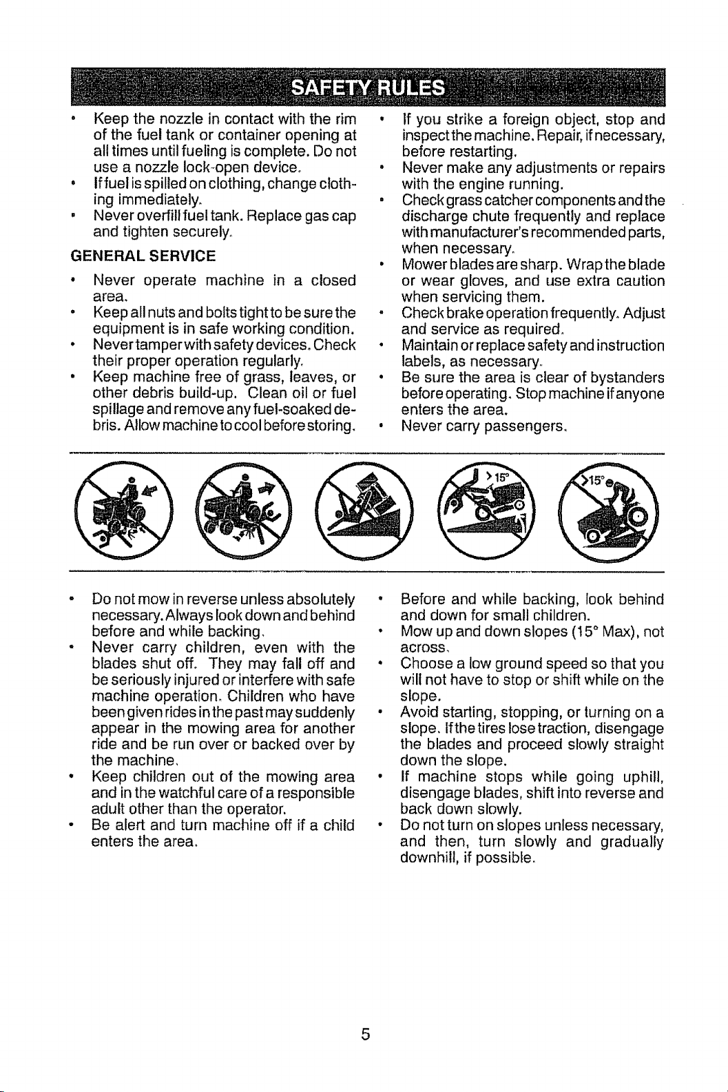
• Mow up and down slopes (15 ° Max), not
across_
• Choose a low ground speed so that you
will not have to stop or shift while on the
slope.
• Avoid starting, stopping, or turning on a
slope. Ifthetires lose traction, disengage
the blades and proceed slowly straight
down the slope.
• If machine stops while going uphill,
disengage blades, shift into reverse and
back down slowly.
• Do notturn on slopes unless necessary,
and then, turn slowly and gradually
downhill, if possible.
5
Page 6

PRODUCT SPECIFICATIONS
Gasoline Capacity 4 Gallons
and Type: Unleaded Regular
Oil Type SAE 10W30(above 32°F)
(API-SG-SL): SAE 5W30(below 32°F
Oil Capacity: 64 oz
Spark Plug: Champion RC12YC
(Gap: .030")
Ground Speed For,_Jard:
(MPH):
Charging System: t5 Amps @ 3600 RPM
Battery: AmpiHr: 28
Blade Bolt Torque: 45-55 Ft. Lbso
CONGRATULATIONS on your purchase of
a new tractor, it has been designed, engi-
neered and manufactured to give you the best
possible dependability and performance.
Should you experience any problem you
cannot easily remedy, please contact a
Sears or other qualified service center. We
have competent, well-trained technicians
and the proper tools to service or repair
this tractor.
Please read and retain this manual. The
instructions will enable you to assemble
and maintain your tractor properly. Always
observe the "SAFETY RULES".
CUSTOMER RESPONSIBILITIES
• Read and observe the safety rules.
• Follow a regular schedule in maintaining,
caring for and using your tractor.
• Follow the instructions under "Mainte-
nance" and "Storage" sections of this
owner's manual.
AI_WARNING: This tractor is equipped with
an internal combustion engine and should not
be used on or near any unimproved forest-
covered, brush-covered or grass-covered
land unless the engine's exhaust system is
equipped with a spark arrester meeting ap-
plicable local or state laws (if any) o if a spark
arrester is used, it should be maintained in
effective working order by the operator_
1st 1.0
2nd 1.4
3rd 2.1
4th 3.1
5th 4.0
6th 5,1
Reverse: 1.6
Mino CCA: 230
Case size: U1R
Inthe state of California the above is required
by law (Section 4442 of the California Public
Resources Code). Other states may have
similar laws. Federal laws apply on federal
lands. A spark arrester for the muffler is
available through your nearest Sears set€ice
center (See REPAIR PARTS manual).
REPAIR PROTECTION
AGREEMENTS
Congratulations on making a smart purchase.
Your new Craftsman@ product is designed
and manufactured for years of dependable
operation. But like all products, it may require
repair from time to time. That's when having
a Repair Protection Agreement can save you
money and aggravation.
Purchase a Repair Protection Agreement
now and protect yourself fiom unexpected
hassle and expense.
Here's what's included in the Agreement:
• Expert service by our 12,000 profesional
repair specialists.
• Unlimited service and no charge for parts
and labor on all covered repairs,
, Product replacement if your covered
product can't be fixed°
• Discount of 10% from regular price of ser-
vice and service-related parts not covered
by the agreement; also, 10% off regular
price of preventive maintenance check.
• Fast help by phone - phone support from
a Sears representative on products requir-
ing imhome repair, plus convenient repair
scheduling.
Once you purchase the Agreement, a
simple phone call is all that it takes for you
to schedule service_ You can call anytime
day or night, or schedule a service appoint-
ment online.
Sears has over 12,000 professiona! repair
specialists, who have access to over 4.5
million quality parts and accessories_ That's
the kind of professionalism you can count on
to help prolong the life of your new purchase
for years to come. Purchase your Repair
Protection Agreement todayE
Some limitations and exclusions apply.
For prices and additional information call
1-800-827-6655.
SEARS INSTALLATION SERVICE
For Sears professional installation of home
appliances, garage door openers, water
heaters, and other major home items, in the
U_S.A, call 1-800-4-MY-HOME®
6
Page 7
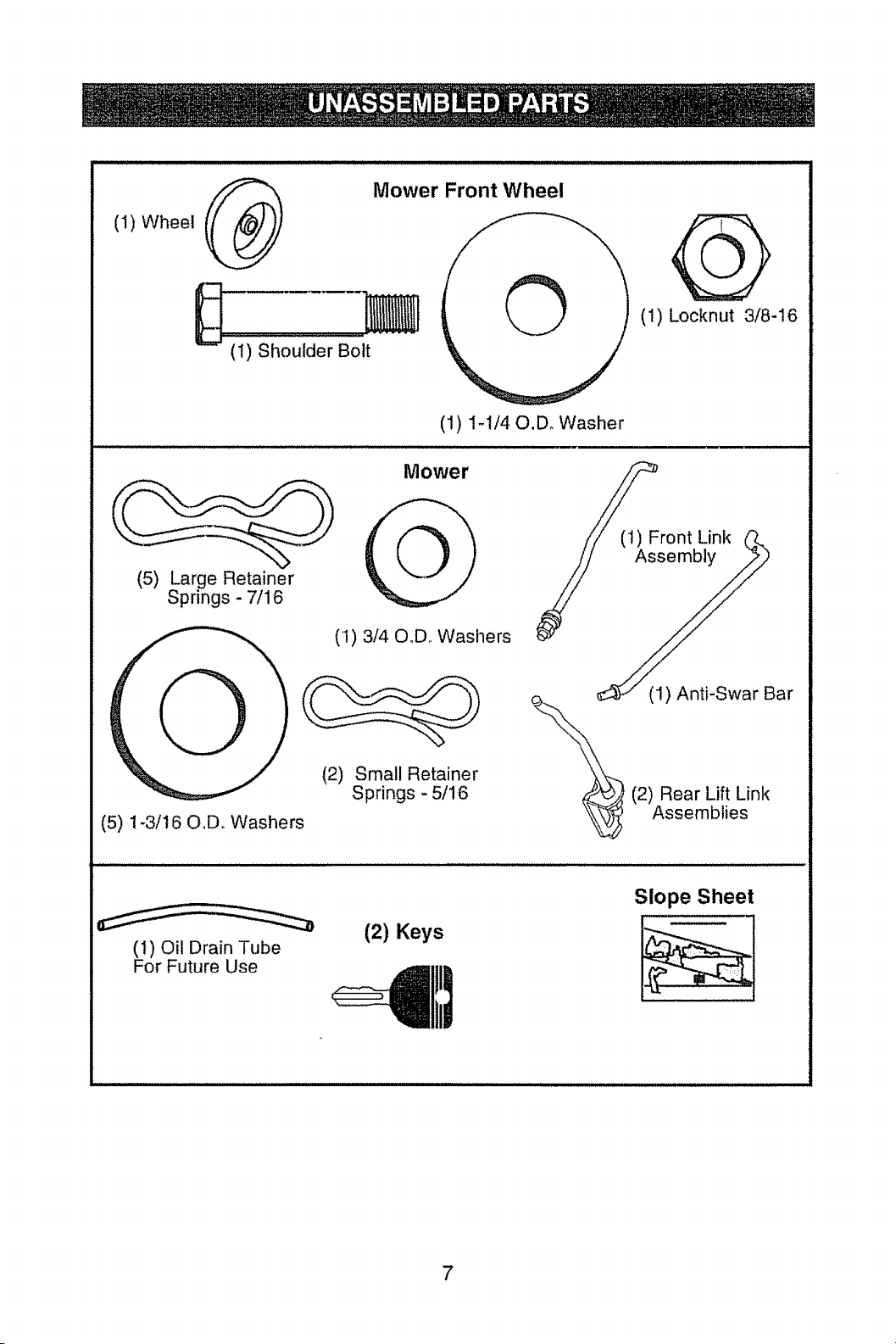
(I) Wheel _1_'_ Mower Front Wheel
(1) Shoulder Bolt
(1) 1-1/40,D. Washer
Mower
(5) Large Retainer
Springs - 7/1 6
(I) 314 O.Do Washers
(1) Locknut 3/8-16
_(t) Front Link (J_.
S __j. (1) Anti-Swar Bar
(5) 1-3/16 O,Do Washers
(i) Oil Drain Tube
For Future Use
(2) Small Retainer
Springs - 5/16
(2) Keys
(2) Rear Lift Link
Assemblies
Slope Sheet
7
Page 8
Your new tractor has been assembled at the factory with exception of those parts left
unassembled for shipping purposes. To ensure safe and proper operation of your tractor
all parts and hardware you assemble must be tightened securely. Use the correct tools
as necessary to insure proper tightness_
TOOLS REQUIRED FOR ASSEMBLY
A socket wrench set will make assembly
easier. Standard wrench sizes are listed.
(2) 7/16" wrenches Utility knife
(1) 1/2" wrench Tire pressure gauge
(1) 3/4" wrench Pliers
(1) 3/4" socket w/drive ratchet
When right or left hand is mentioned in this
manual, itmeanswhenyou are inthe operating
position (seated behind the steering wheel).
TO REMOVE TRACTOR FROM
CARTON
UNPACK CARTON
. Remove all accessible loose parts and
parts cartons from carton.
o Cut along dotted lines on all four panels
of carton. Remove end panels and lay
side panels flat.
• Remove mower and packing materials.
• Check for any additional loose parts or
cartons and remove.
BEFORE REMOVING TRACTOR
FROM SKID
TO CHECK BATTERY
1, Uf_ hood to raised position.
NOTE: If this battery is put into service after
month and year indicated on label (label is
located between terminals) charge battery
for minimum of one hour at 6-10 amps, (See
"BATTERY" in Maintenance section of this
manual for charging instructions),
• Forbatteryand batterycableinstatlationsee
"R EPLACING BATTERY" inthe "Service
and Adjustments" section in this manual.
Label
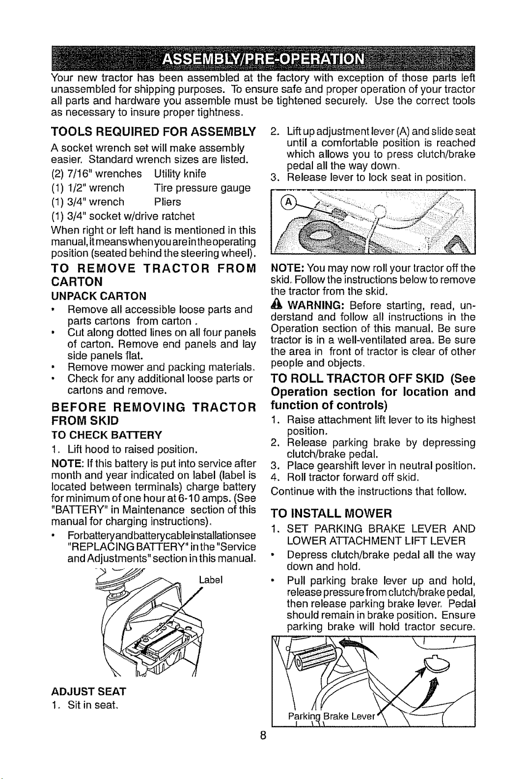
2. Lift up adjustment lever (A) and slide seat
until a comfortable position is reached
which allows you to press clutch/brake
pedal all the way down.
3. Release lever to lock seat in position.
NOTE: You may now roll your tractor off the
skid° Follow the instructions below to remove
the tractor from the skid.
d_, WARNING: Before starting, read, un-
derstand and follow all instructions in the
Operation section of this manual. Be sure
tractor is in a well-ventilated area° Be sure
the area in front of tractor is clear of other
people and objects.
TO ROLL TRACTOR OFF SKID (See
Operation section for location and
function of controls)
I. Raise attachment lift lever to its highest
position,
2. Release parking brake by depressing
clutch/brake pedal,
3. Place gearshift lever in neutral position,
4. Roll tractor forward off skid.
Continue with the instructions that follow.
TO INSTALL MOWER
I. SET PARKING BRAKE LEVER AND
LOWER ATTACHMENT LIFT LEVER
Depress clutch/brake pedal all the way
down and holdo
Pull parking brake lever up and hold,
release pressure from clutch!brake pedal,
then release parking brake lever. Pedal
should remain in brake position. Ensure
parking brake wilt hold tractor secure.
1. Sit in seat.
Brake
Page 9
_CAUTION: Lift lever is spring loaded 3.
Have a tight grip on lift lever, lower it slowly
and engage in lowest position° Lift lever is •
located on left side of fender.
Lift
Lever
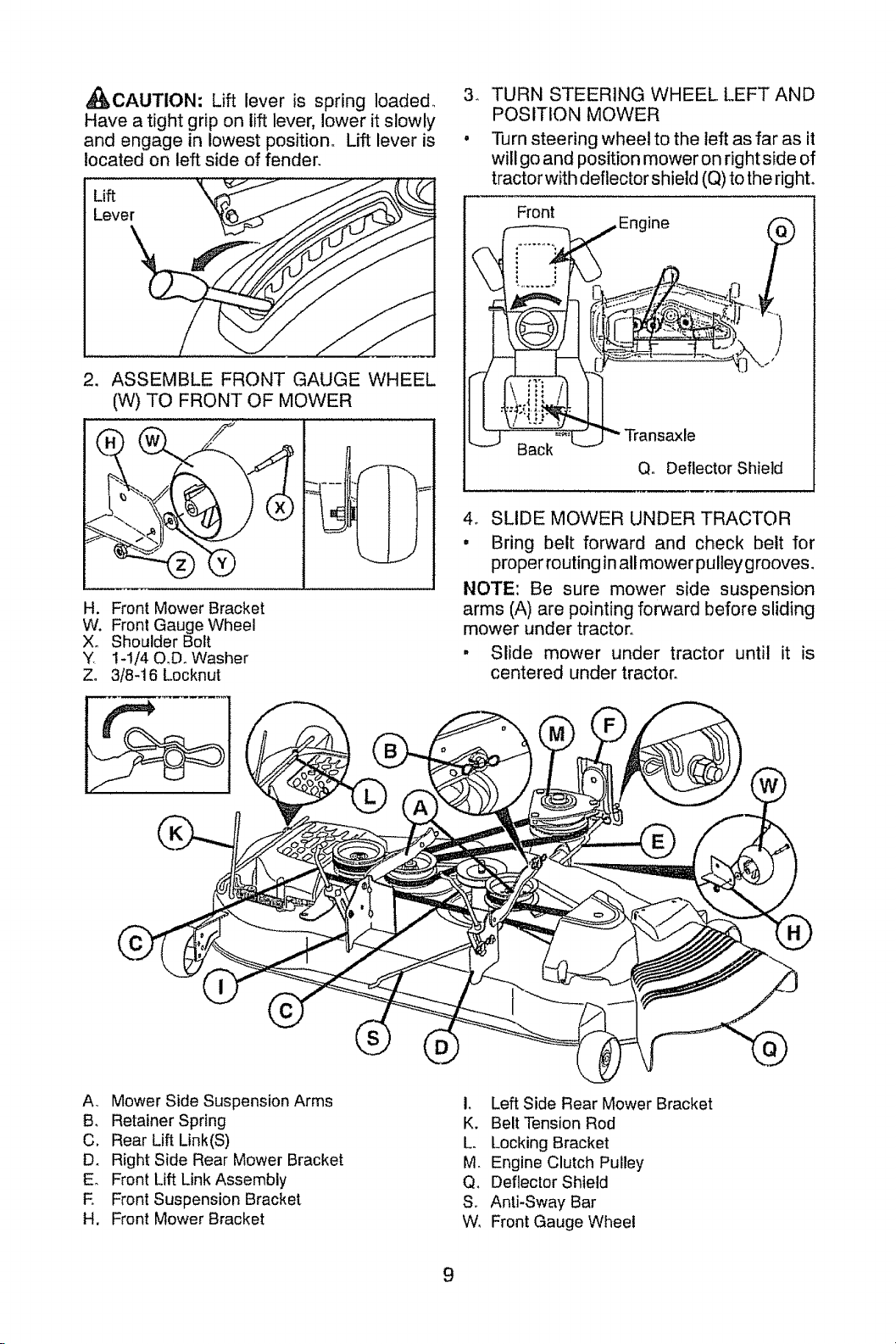
. ASSEMBLE FRONT GAUGE WHEEL
(W) TO FRONT OF MOWER
-®
H. Front Mower Bracket
W. Front Gauge Wheel
Xo Shoulder Bolt
¥ 1-I/40,D. Washer
Z. 3/8-16 Locknut
TURN STEERING WHEEL LEFT AND
POSITION MOWER
Turn steering wheel to the left as far as it
will go and position mower on right side of
tractor with deflector shield (Q) to the right.
Front
(
,)
Back
Q. Deflector Shield
4. SLIDE MOWER UNDER TRACTOR
• Bring belt forward and check belt for
proper routing in all mower pulley grooves _
NOTE: Be sure mower side suspension
arms (A) are pointing forward before sliding
mower under tractor.
° Slide mower under tractor until it is
centered under tractor.
A, Mower Side Suspension Arms
B, Retainer Spring
C. Rear Lift Link(S)
Dr Right Side Rear Mower Bracket
E. Front Lift Link Assembly
E Front Suspension Bracket
H. Front Mower Bracket
I, Left Side Rear Mower Bracket
K. Belt Tension Rod
L. Locking Bracket
M Engine Clutch Pulley
Q, Deflector Shield
S. Anti-Sway Bar
W, Front Gauge Wheel
9
Page 10
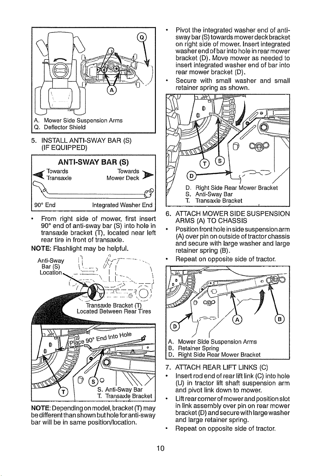
A. Mower Side Suspension Arms
Qo Deflector Shield
5. INSTALLANTI-SWAY BAR (S)
(IF EQUIPPED)
Towards Towards
i_ ANTI-SWAY BAR (S)
Transaxle Mower Deck
° Pivot the integrated washer end of anti-
sway bar (S) towards mower deck bracket
on right side of mower. Insert integrated
washer end of bar into hole in rear mower
bracket (D), Move mower as needed to
insert integrated washer end of bar into
rear mower bracket (D).
. Secure with small washer and small
retainer spring as shown,
90° End
From right side of mower, first insert
90 ° end of anti-sway bar (S) into hole in
transaxte bracket (T), located near left
rear tire in front of transaxle,
NOTE: Depending on model, bracket (T) may
be different than shown but hole for anti-sway
bar will be in same position/location,
Integrated Washer End
T. Transaxle Bracket
6. ATTACH MOWER SIDE SUSPENSION
ARMS (A) TO CHASSIS
• Position front hole inside suspension arm
(A) over pin on outside of tractor chassis
and secure with large washer and large
retainer spring (B).
, Repeat on opposite side of tractor.
A, Mower Side Suspension Arms
B, Retainer Spring
D. Right Side Rear Mower Bracket
7, ATTACH REAR LIFT LINKS (C)
• Insert rod end of rear lift link (C) into hole
(U) in tractor lift shaft suspension arm
and pivot link down to mower,
• Lift rear corner of mower and position slot
in link assembly over pin on rear mower
bracket (D) and secure with large washer
and large retainer spring,
• Repeat on opposite side of tractor,
I0
Page 11
,./
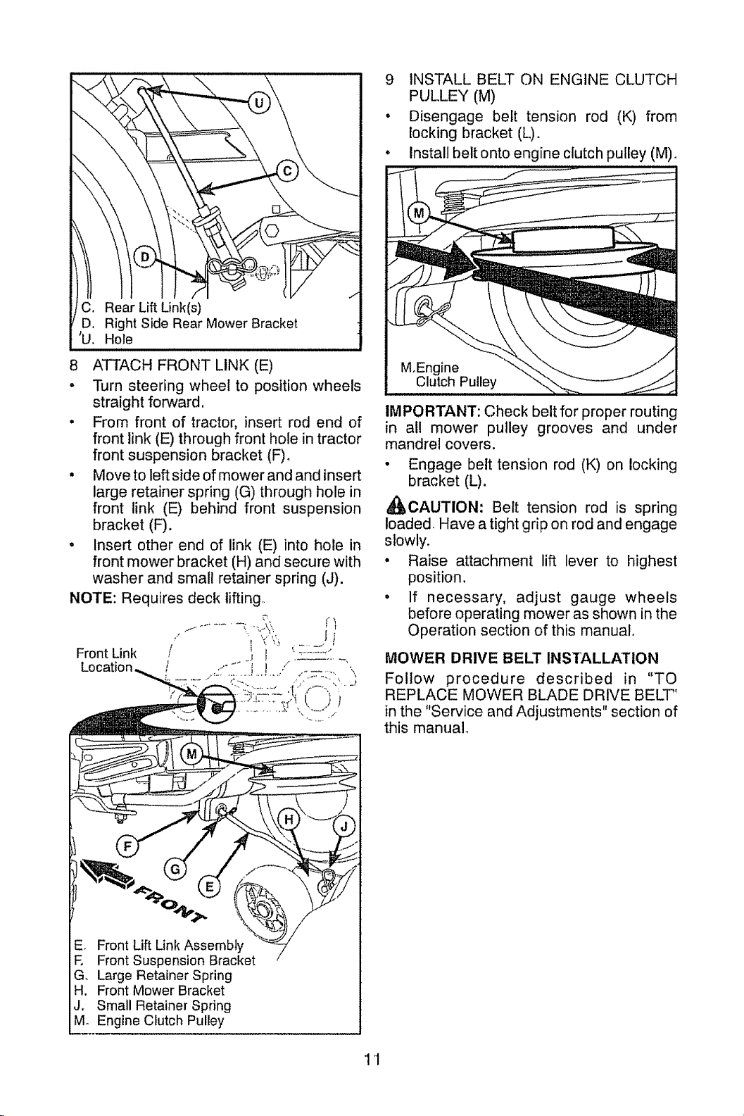
ar Lift Link(s)
I/ D. Right Side Rear Mower Bracket
[ 'U. Hole
8 ATTACH FRONT LINK (E)
• Turn steering wheel to position wheels
straight forccard.
• From front of tractor, insert rod end of
front tink (E) through front hole in tractor
front suspension bracket (F),
• Moveto left side of mower and and insert
large retainer spring (G) through hole in
front link (E) behind front suspension
bracket (F).
. Insert other end of link (E) into hole in
front mower bracket (H) and secure with
washer and small retainer spring (J).
NOTE: Requires deck lifting
.... ! ,(,:_:_....... J;
Front Link / ' ' "
/ .,_°.....i I ./ ...........'\
.....;.......;:................... ..........(,,.;
9 INSTALL BELT ON ENGINE CLUTCH
PULLEY (M)
- Disengage belt tension rod (K) from
locking bracket (L),
- Install belt onto engine clutch pulley (M),
M°Engine
Clutch Pulley
IMPORTANT: Check belt for proper routing
in all mower pulley grooves and under
mandrel covers.
• Engage belt tension rod (K) on locking
bracket (L).
_CAUTION: Belt tension rod is spring
loaded. Have a tight grip on rod and engage
slowty.
• Raise attachment lift lever to highest
position.
° If necessary, adjust gauge wheels
before operating mower as shown in the
Operation section of this manual,
MOWER DRIVE BELT INSTALLATION
Follow procedure described in "TO
REPLACE MOWER BLADE DRIVE BELT"
in the "Service and Adjustments" section of
this manual_
"_'_O4_ _"- %
Front Lift Link Assembly
E Front Suspension Bracket--
G. Large Retainer Spring
H. Front Mower Bracket
t_ Small Retainer Spring
. Engine Clutch Pulley
11
Page 12
CHECK TIRE PRESSURE
The tires on your tractor were over-inflated
at the factory for shipping purposes. Correct
tire pressure is important for best cutting
performance.
• Reduce tire pressure to PSt shown on tires.
CHECK DECK LEVELNESS
For best cutting results, mower housing
should be properly leveled. See "TO LEVEL
MOWER" in the Service and Adjustments
section of this manual.
CHECK FOR PROPER POSITION OF
ALL BELTS
See the figures that are shown for replacing
motion and mower blade drive belts in the
Service and Adjustments section of this man-
ual. Verify that the belts are routed correctly.
CHECK BRAKE SYSTEM
After you learn how to operate your tractor,
check to see that the brake is operating prop-
erlyo See"TO CHECK B RAKE"in the Service
and Adjustments section of this manual.
_'CHECKLIST
Before you operate your new tractor, we
wish to assure that you receive the best
performance and satisfaction from this
Quality Product°
Please review the following checklist:
J" All assembly instructions have been
completed.
J" No remaining loose parts in carton.
_/" Battery is properly prepared and
charged.
_/' Seat is adjusted comfortably and tight-
ened securely.
All tires are properly inflated. (For ship-
ping purposes, the tires were overinflated
at the factory).
Vf Be sure mower deck is properly leveled
side-to-side/front-to-rear for best cutting
results. (Tires must be properly inflated
for leveling).
J" Check mower and drive belts. Be sure
they are routed properly around pulleys
and inside all belt keepers.
J" Check wiring, See that all connections
are still secure and wires are properly
clamped.
While learning how to use your tractor, pay ex-
tra attention to the following important items:
_/' Engine oil is at proper level°
J' Fueltank is filled with fresh, clean, regular
unleaded gasoline.
J" Become familiar with all controls, their
location and function. Operate them
before you start the engine.
v# Besure brake system is in safe operating
condition.
J" Be sure Operator Presence System and
Reverse Operation System (ROS) are
working properly (See the Operation and
Maintenance sections in this manual).
12
Page 13

These symbols may appear on your tractor or in literature supplied with the product,
Learn and understand their meaning,
R N H L
REVERSE NEUTRAL HIGH LOW
CHOKE FAST SLOW
IGNITION SWITCH
ENGINE OFF REVERSE ENGINE ON ENGINE START
LIGHTS ON
ATTACHMENT ATTACHMENT DANGER_ KEEP HANDS
CLLrrCH DISENGAGED CLUTCH ENGAGED AND FEETAWAY
(Autom,_tlc Models only)
OPERATION
SYSTEM EROS)
FUEL
FREE WHEEL
BATTERY REVERSE FORWARD
A
Failure to follow instructions
could result in serious injury or
death. The safety alert symbol
is used to identify safety inform-
ation about hazards which can
result in death, serious injury
and/or property damage,
lm=_====l
PARKING BRAKE MOWER HEIGHT
;r
t
KEEP AREA CLEAR SLOPE HAZARDS
(SEE SAFETY RULES SECTION)
DANGER indicates a hazard wf_ich,if not avoided,
will result in death or serious injury.
WARNING indicates a hazard which, if not avoided,
could result in death or serious injury.
CAUTION indicates a hazard which, if not avoided,
might result in minor or moderate injury.
CAUTION when used without the alert symbot,
indicates a situation that could result in damage
to the tractor and/or engine.
HOT SURFACES indicates a hazard which,
if not avoided, could result in death, serious injury
and/or property damage,
FIRE indicates a hazard wllich, if ROtavoided,
could result In death, serious injury andlor
property damage.
MOWER LIFT
13
Page 14
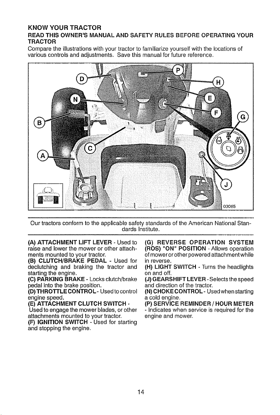
KNOW YOUR TRACTOR
READ THIS OWNER'S MANUAL AND SAFETY RULES BEFORE OPERATING YOUR
TRACTOR
Compare the illustrations with your tractor to familiarize yourself with the locations of
various controls and adjustments_ Save this manual for future reference_
::
O3O65
Our tractors conform to the applicable safety standards of the American National Stan-
dards Institute°
(A) ATTACHMENT LIFT LEVER - Used to
raise and lower the mower or other attach-
ments mounted to your tractor°
(B) CLUTCH/BRAKE PEDAL- Used for
declutching and braking the tractor and
starting the engine.
(C) PARKING BRAKE - Locks clutch/brake
pedal into the brake position.
(D) THROTTLE CONTROL- Used to control
engine speed.
(E) ATTACHMENT CLUTCH SWITCH -
Used to engage the mower blades, or other
attachments mounted to your tractor.
(G) REVERSE OPERATION SYSTEM
(ROS) "ON" POSITION - Allows operation
of mower or other powe red attachment while
in reverse.
(H) LIGHT SWITCH - Turns the headlights
on and off.
(J) GEARSHIFT LEVER *Selects the speed
and direction of the tractor.
(N) CHOKE CONTROL- Used when starting
a cold engine_
(P) SERVICE REMINDER / HOUR METER
- Indicates when service is required for the
engine and mower°
(F) IGNITION SWITCH - Used for starting
and stopping the engine.
14
Page 15
The operation of any tractor can result in foreign objects thrown into the
eyes, which can result in severe eye damage. Always wear safety glasses
or eye shields while operating your tractor or performing any adjustments
or repairs. We recommend standard safety glasses or a wide vision safety
mask worn over spectacles.
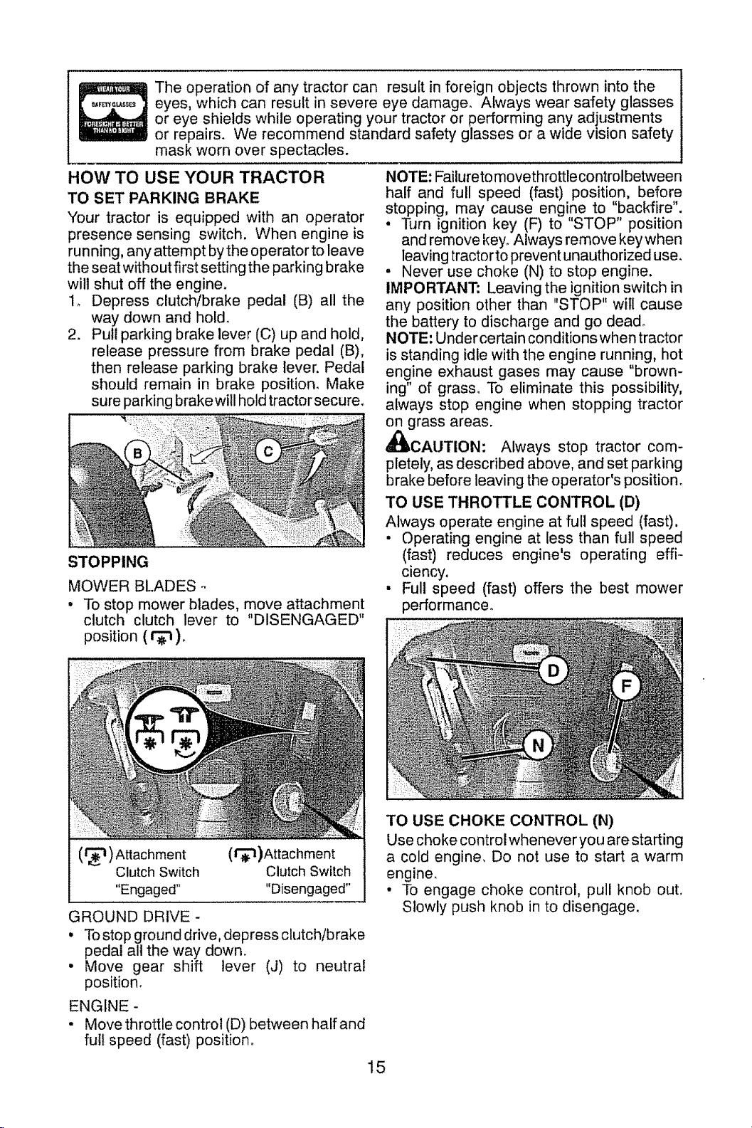
HOW TO USE YOUR TRACTOR
TO SET PARKING BRAKE
Your tractor is equipped with an operator
presence sensing switch, When engine is
run ning, any attempt by the operator to leave
the seat without first setting the parking b rake
will shut off the engine.
1. Depress clutch/brake pedal (B) all the
way down and hol&
2, Pull parking brake lever (C) up and hold,
release pressure from brake pedal (B),
then release parking brake lever. Pedal
should remain in brake position_ Make
sure parking brake will hold tractor secure.
STOPPING
MOWER BLADES o
- To stop mower blades, move attachment
clutch clutch lever to "DISENGAGED"
position ( r_ )_
NOTE: Failureto movethrottle control between
half and full speed (fast) position, before
stopping, may cause engine to "backfire".
• Turn ignition key (F) to "STOP" position
and remove key. Always remove key when
leaving tractor to prevent unauthorized use_
, Never use choke (N) to stop engine.
IMPORTANT: Leaving the ignition switch in
any position other than "STOP" will cause
the battery to discharge and go dead°
NOTE: Under certain conditions when tractor
is standing idle with the engine running, hot
engine exhaust gases may cause "brown-
ing" of grass° To eliminate this possibility,
always stop engine when stopping tractor
on grass areas.
_IbCAUTION: Always stop tractor com-
pletely, as described above, and set parking
brake before leaving the operator's position°
TO USE THROTTLE CONTROL (D)
Always operate engine at full speed (fast).
• Operating engine at less than full speed
(fast) reduces engine's operating effi-
ciency,
• Full speed (fast) offers the best mower
performance.
(_) Attachment
Clutch Switch
"Engaged"
GROUND DRIVE-
o To stop ground drive, depress clutch/brake
pedal all the way down.
• Move gear shift lever (J) to neutral
position,
ENGINE -
- Move throttle control (D) between half and
full speed (fast) position.
(l'_)Attachment
Clutch Switch
"Disengaged"
TO USE CHOKE CONTROL (N)
Use choke controtwhenever you are starting
a cold engine, Do not use to start a warm
engine.
• To engage choke control, pull knob out,
Slowly push knob in to disengage.
15
Page 16
TO MOVE FORWARD AND BACKWARD
The direction and speed of movement is
controlled by the gearshift lever (J).
1, Start tractor with clutch/brake pedal
depressed and gearshift lever in neutral
position.
2. Move gearshift lever to desired position.
3. Slowly release clutch/brake pedal to start
movement.
IMPORTANT: Bringtractorto acompletestop
before shifting orchanging gears° Failure to do
so will shorten the useful fife of your transaxle.
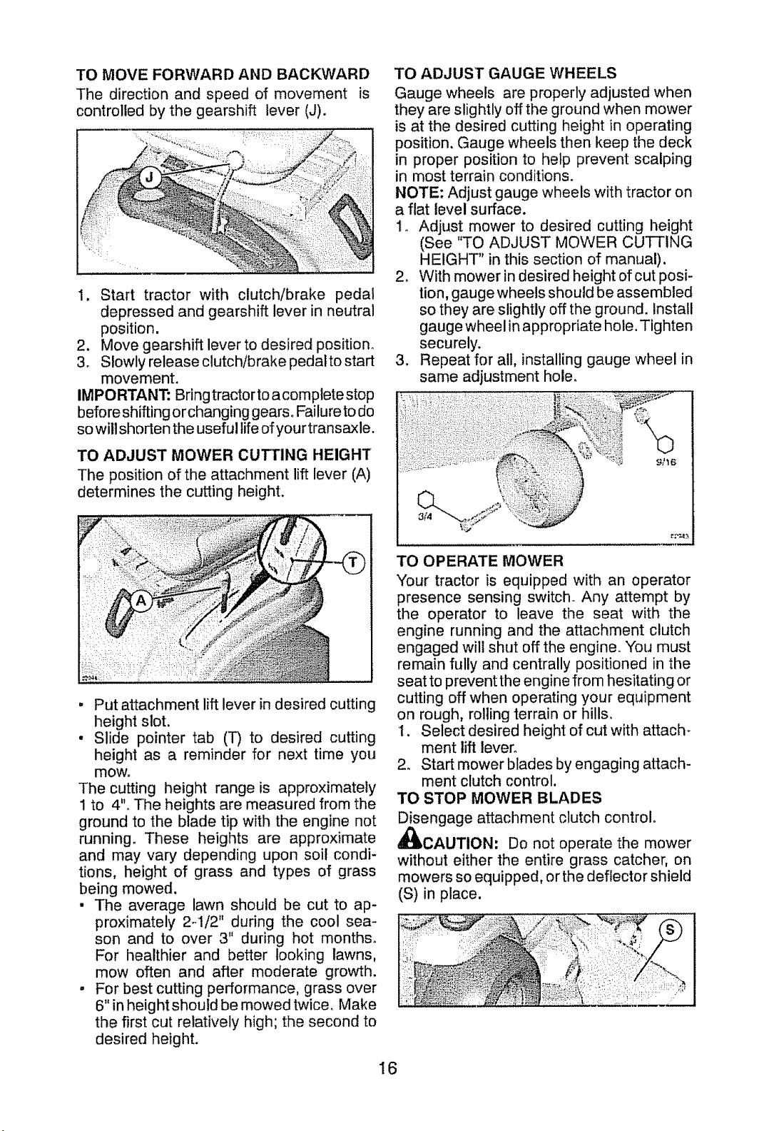
TO ADJUST MOWER CUTTING HEIGHT
The position of the attachment lift lever (A)
determines the cutting height.
TO ADJUST GAUGE WHEELS
Gauge wheels are properly adjusted when
they are slightly off the ground when mower
is at the desired cutting height in operating
position, Gauge wheels then keep the deck
in proper position to help prevent scalping
in most terrain conditions.
NOTE: Adjust gauge wheels with tractor on
a flat level surface.
1o Adjust mower to desired cutting height
(See "TO ADJUST MOWER CUTTING
HEIGHT" in this section of manual),
2, With mower in desired height of cut posi-
tion, gauge wheels should be assembled
so they are slightly off the ground. Install
gauge wheel in appropriate hole. Tighten
securely.
3, Repeat for all, installing gauge wheel in
same adjustment hole,
, Put attachment lift lever in desired cutting
height slot.
• Slide pointer tab (T) to desired cutting
height as a reminder for next time you
mow.
The cutting height range is approximately
1 to 4"° The heights are measured from the
ground to the blade tip with the engine not
running. These heights are approximate
and may vary depending upon soil condi-
tions, height of grass and types of grass
being mowed.
• The average lawn should be cut to ap-
proximately 2q/2" during the cool sea-
son and to over 3" during hot months°
For healthier and better looking lawns,
mow often and after moderate growth.
, For best cutting performance, grass over
6" in height should be mowed twice, Make
the first cut relatively high; the second to
desired height,
TO OPERATE MOWER
Your tractor is equipped with an operator
presence sensing switch_ Any attempt by
the operator to leave the seat with the
engine running and the attachment clutch
engaged will shut off the engine You must
remain fully and centrally positioned in the
seat to prevent the engine from hesitating or
cutting off when operating your equipment
on rough, rolling terrain or hills.
1. Select desired height of cut with attach-
ment lift lever°
2o Start mower blades by engaging attach-
ment clutch control.
TO STOP MOWER BLADES
Disengage attachment clutch control.
A
_CAUTION: Do not operate the mower
without either the entire grass catcher, on
mowers so equipped, or the deflector shield
(S) in place.
16
Page 17
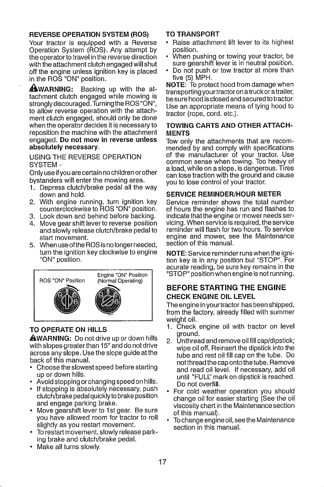
REVERSE OPERATION SYSTEM (ROS)
Your tractor is equipped with a Reverse
Operation System (ROS). Any attempt by
the operator to travel in the reverse direction
with the attachment clutch engaged will shut
off the engine unless ignition key is placed
in the ROS "ON" position.
•_WARNING: Backing up with the at-
tachment clutch engaged while mowing is
strongly discou raged, Turning the ROS "ON",
to allow reverse operation with the attach-
ment clutch engaged, should only be done
when the operator decides it is necessary to
reposition the machine with the attachment
engaged. Do not mow in reverse unless
absolutely necessary,
USING THE REVERSE OPERATION
SYSTEM o
Only use ifyou are certain no children or other
bystanders will enter the mowing area,
1, Depress clutch/brake pedal all the way
down and hold,
2. With engine running, turn ignition key
counterclockwise to ROS "ON" position,
3_ Look down and behind before backing,
4, Move gear shift lever to reverse position
and slowly release clutch/brake pedal to
start movement.
5, When use ofthe ROS isno longerneeded,
turn the ignition key clockwise to engine
"ON" position,
ROS "ON" Position
TO OPERATE ON HILLS
_WARNING: Do not drive up or down hills
with slopes greater than 15 0and do not drive
across any slope° Use the slope guide atthe
back of this manual.
• Choose the slowest speed before starting
up or down hills,
• Avoid stopping or changing speed on hills.
, if stopping is absolutely necessary, push
clutch/brake pedal quickly to brake position
and engage parking brake,
• Move gearshift lever to 1st gear. Be sure
you have allowed room for tractor to roll
slightly as you restart movement,
. ]b restart movement, slowly release park-
ing brake and clutch/brake pedal,
• Make all turns slowly,
Engine "ON" Position
(Norrnal Operating)
TO TRANSPORT
• Raise attachment lift lever to its highest
position.
. When pushing or towing your tractor, be
sure gearshift lever is in neutral position.
• Do not push or tow tractor at more than
five (5) MPH_
NOTE: To protect hood from damage when
transporting your tractor on a truck or atrailer,
be sure hood is closed and secured to tractor
Use an appropriate means of tying hood to
tractor (rope, cord, etc,),
TOWING CARTS AND OTHER ATTACH-
MENTS
Tow only the attachments that are recom_
mended by and comply with specifications
of the manufacturer of your tractor. Use
common sense when towing, Too heavy of
a load, while on a slope, is dangerous, Tires
can lose traction with the ground and cause
you to lose control of your tractor,
SERVICE REMINDER/HOUR METER
Service reminder shows the total number
of hours the engine has run and flashes to
indicate that the engine or mower needs ser-
vicing, When service is required, the service
reminder will flash for two hours° To service
engine and mower, see the Maintenance
section of this manual,
NOTE: Service reminder runs when the igni-
tion key is in any position but "STOP", For
acurate reading, be sure key remains in the
"STOP" position when engine is not running.
BEFORE STARTING THE ENGINE
CHECK ENGINE OIL LEVEL
The engine in yourtractor has been shipped,
from the factory, already filled with summer
weight oil,
1_ Check engine oil with tractor on level
ground.
2, Unthread and remove oil fill cap/dipstick;
wipe oil off. Reinsert the dipstick into the
tube and rest oil fill cap on the tube. Do
not thread the cap onto the tube. Remove
and read oil level, If necessary, add oil
until "FULL' mark on dipstick is reached,
Do not overfill,
• For cold weather operation you should
change oil for easier starting (See the oil
viscosity chart in the Maintenance section
of this manual)_
• To change engine oil, see the Maintenance
section in this manual.
17
Page 18
ADD GASOLINE
" Fill fuel tank to bottom of filler neck. Do
not overfill, Use fresh, clean, regular
unleaded gasoline with a minimum of
87 octane° (Use of leaded gasoline will
increase carbon and lead oxide deposits
and reduce valve life)_ Do not mix oil with
gasoline. Purchase fuel in quantities that
can be used within 30 days to assure fuel
freshness.
_CAUTION: Wipe off any spilled oil or fuel.
Do not store, spill or use gasoline near an
open flame.
IMPORTANT: When operating in tempera-
tures below32°F(0°C), use fresh, clean winter
grade gasoline to help ensure good cold
weather starting.
CAUTION: Alcohol blended fuels (called
gasohol or using ethanol or methanol) can
attract moisture which leads to separation
and formation of acids during storage. Acidic
gas can damage the fuel system of an engine
while in storage. To avoid engine problems,
the fuel system should be emptied before
storage of 30 days or longer. Drain the gas
tank, start the engine and let it run until the
fuel lines and carburetor are empty° Use fresh
fuel next season, See Storage Instructions
for additional information. Never use engine
or carburetor cleaner products in the fuettank
or permanent damage may occur.
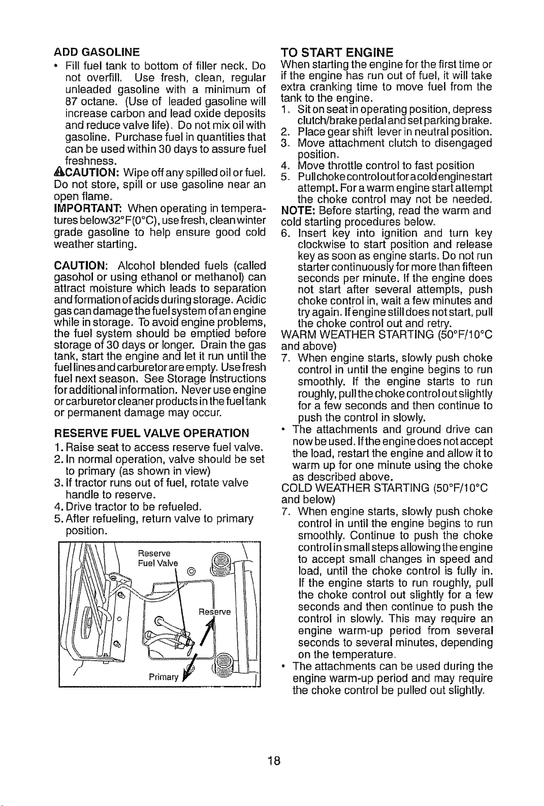
RESERVE FUEL VALVE OPERATION
1. Raise seat to access reserve fuel valve.
2. In normal operation, valve should be set
to primary (as shown in view)
3. If tractor runs out of fuel, rotate valve
handle to reserve.
4. Drive tractor to be refueled.
5. After refueling, return valve to primary
position.
Reserve
Fuel VaDe
@
Primary
TO START ENGINE
When starting the engine for the first time or
if the engine has run out of fuel, it will take
extra cranking time to move fuel from the
tank to the engine.
I. Siton seat in operating position, depress
clutch/b rake pedal and set parking brake.
2. Place gear shift lever in neutral position.
3. Move attachment clutch to disengaged
position.
4. Move throttle control to fast position
5. Pullchoke controloutfor a cold enginestart
attempt. For awarm engine start attempt
the choke control may not be needed.
NOTE: Before starting, read the warm and
cold starting procedures below.
6. insert key into ignition and turn key
clockwise to start position and release
key as soon as engine starts. Do not run
starter continuously for more than fifteen
seconds per minute. If the engine does
not start after several attempts, push
choke control in, wait a few minutes and
try again. If engine still does not start, pull
the choke control out and retry.
WARM WEATHER STARTING (50°F/10°C
and above)
7. When engine starts, slowly push choke
control in until the engine begins to run
smoothly. If the engine starts to run
roughly, pull the choke control out slightly
for a few seconds and then continue to
push the control in slowly,
° The attachments and ground drive can
now be used. if the engine does not accept
the load, restart the engine and allow it to
warm up for one minute using the choke
as described above.
COLD WEATHER STARTING (50°F/10°C
and below)
7. When engine starts, slowly push choke
control in until the engine begins to run
smoothly. Continue to push the choke
control in small steps allowing the engine
to accept small changes in speed and
load, until the choke control is fully in.
if the engine starts to run roughly, pull
the choke control out slightly for a few
seconds and then continue to push the
control in slowly. This may require an
engine warm-up period from several
seconds to several minutes, depending
on the temperature.
• The attachments can be used during the
engine warm-up period and may require
the choke control be pulled out slightly.
18
Page 19
NOTE; If at a high altitude (above 3000
feet) or in cold temperatures (below 32°F)
the carburetor fuel mixture may need to be
adjusted for best engine performance. See
"TO ADJUST CARBURETOR" in the Service
and Adjustments section of this manual.
MOWING TIPS
, Tire chains cannot be used when the
mower housing is attached to tractor.
• Mowershould be properly leveled for best
mowing performance_ See "TO LEVEL
MOWER HOUSING" in the Service and
Adjustments section of this manual.
• The left hand side of mower should be
used for trimming.
• Drive so that clippings are discharged
onto the area that has already been cut.
Have the cut area to the right of the tractor,
This will result in a more even distribution
of clippings and more uniform cutting.
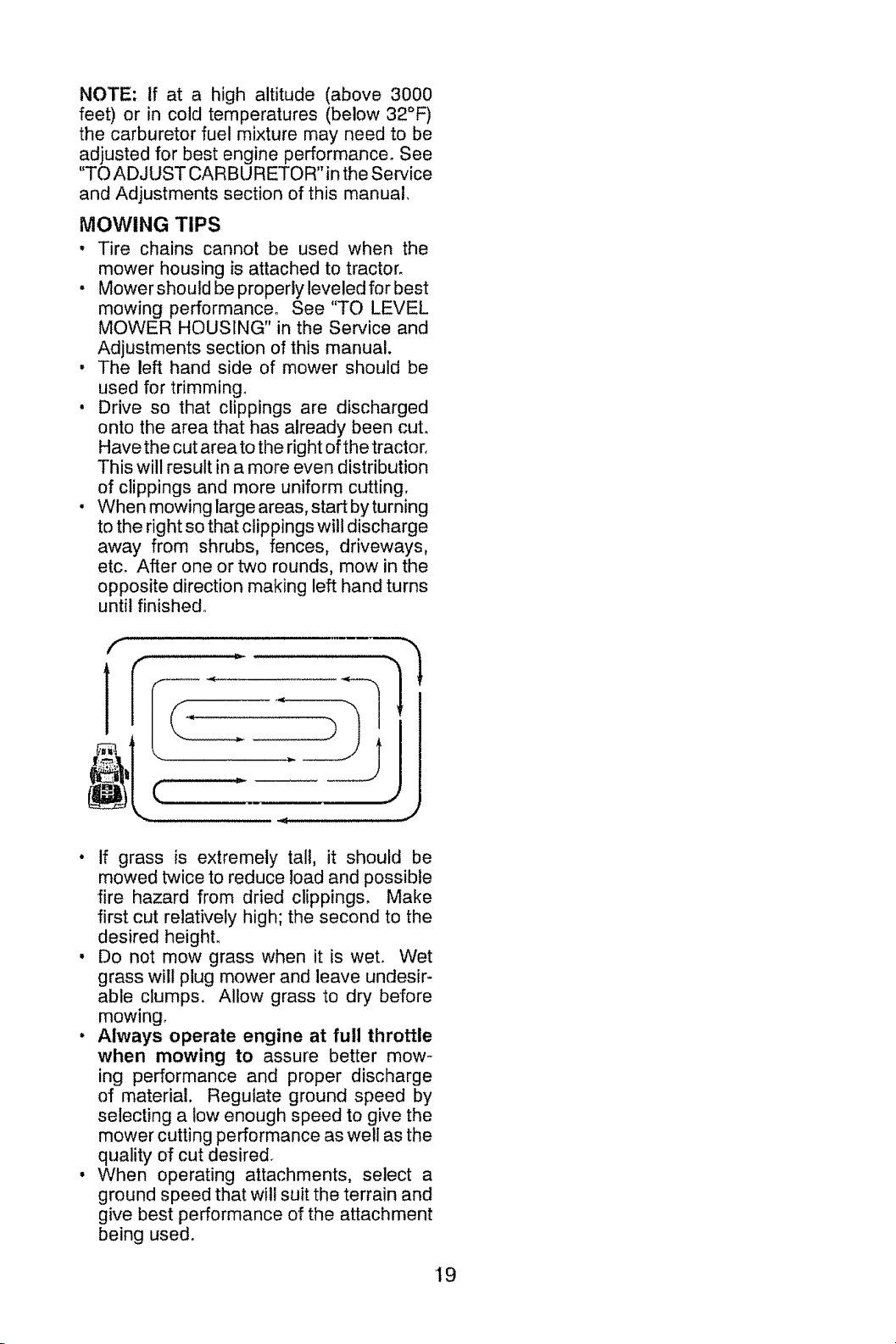
• When mowing large areas, start by turning
to the right so that clippings will discharge
away from shrubs, fences, driveways,
etc. After one or two rounds, mow in the
opposite direction making left hand turns
until finished.
f
• If grass is extremely tall, it should be
mowed twice to reduce load and possible
fire hazard from dried clippings. Make
first cut relatively high; the second to the
desired height.
• Do not mow grass when it is wet. Wet
grass will plug mower and leave undesir-
able clumps. Allow grass to dry before
mowing,
• Always operate engine at full throttle
when mowing to assure better mow-
ing performance and proper discharge
of material. Regulate ground speed by
selecting a low enough speed to give the
mower cutting performance as well as the
quality of cut desired_
• When operating attachments, select a
ground speed that will suit the terrain and
give best performance of the attachment
being used.
'19
Page 20
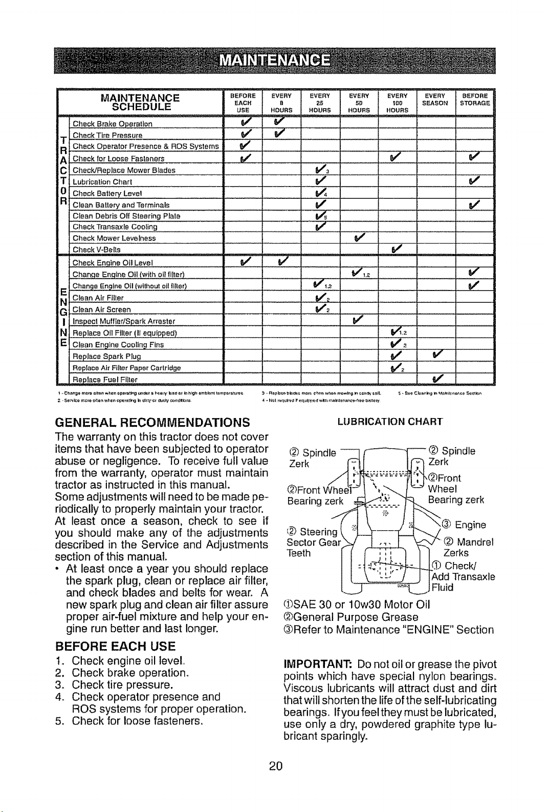
MAINTENANCE B'E_o'RE'" EVEn'l EVEm' EVERY EVERY EVERY BEFORE
SCHEDULE EACH _ 25 51:} t_0 SEASON STORAGE
Check Brake Operation 6_
U_;E HOURS HOURS HOURS HOURS
CheckT_roP,eosoro V" _ t _iiii] i iiiiiiiiiiii]iiiiiiiiiiiiiii/iiii
T CheekOperatorPresence&ROSsystems! _ i I I f I
R I , I I ilLi::iil:iliii "
A
C V'_
Check/Replace Mower Blades ..................
T Lubrication Chart 6/'
0 CheckB.fie,_.LeVe, V'.
R Clean Batlery andTermi,nals _' V I
Clean Debris Off Steering Plate
Check Transaxfe Cooling .............. _ ' ' '
Check Mower Levelness
Check V-Bells rvf
Check Eng!ne O!! Leve! _
Change Engine Oil (with oil [liter) .................... !_l,z ........... !_
E Change Engine Oil (wil!)ou! 0tl i!!!#r ) ...............................................
N C!ea# A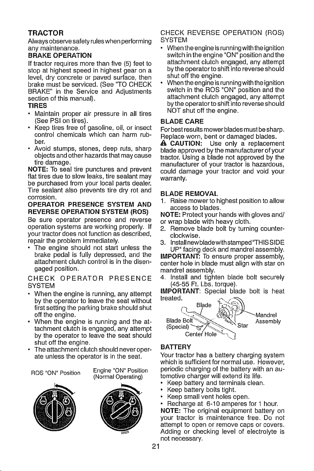
TRACTOR
Always observe safety rules when performing
any maintenance,
BRAKE OPERATION
if tractor requires more than five (5) feet to
stop at highest speed in highest gear on a
level, dry concrete or paved surface, then
brake must be serviced. (See "TO CHECK
BRAKE" in the Service and Adjustments
section of this manual).
TIRES
- Maintain proper air pressure in all tires
(See PSI on tires).
° Keep tires free of gasoline, oi!, or insect
control chemicals which can harm rub-
bero
° Avoid stumps, stones, deep ruts, sharp
objects and other hazards that may cause
tire damage.
NOTE: To sea! tire punctures and prevent
flat tires due to slow leaks, tire sealant may
be purchased from your local parts dealer,
Tire sealant also prevents tire dry rot and
corrosion.
OPERATOR PRESENCE SYSTEM AND
REVERSE OPERATION SYSTEM (ROS)
Be sure operator presence and reverse
operation systems are working properly. If
your tractor does not function as described,
repair the problem immediately_
• The engine should not start unless the
brake pedal is fully depressed, and the
attachment clutch control is in the disen-
gaged position.
CHECK OPERATOR PRESENCE
SYSTEM
, When the engine is running, any attempt
by the operator to leave the seat without
first setting the parking brake should shut
off the engine.
• When the engine is running and the at_
tachment clutch is engaged, any attempt
by the operator to leave the seat should
shut off the engine.
o The attachment clutch should never oper-
ate unless the operator is in the seat.
ROS "ON" Position
Engine "ON" Position
(Normal Operating)
CHECK REVERSE OPERATION (ROS)
SYSTEM
, When the engine is running with the ignition
switch in the engine "ON" position and the
attachment clutch engaged, any attempt
by the operator to shift into reverse should
shut off the engine.
• When the engine is running with the ignition
switch in the ROS "ON" position and the
attachment clutch engaged, any attempt
by the operator to shift into reverse should
NOT shut off the engine.
BLADE CARE
For best results mower blades must be sharp.
epface worn, bent or damaged blades.
CAUTION: Use only a replacement
blade approved by the manufacturer of your
tractor. Using a blade not approved by the
manufacturer of your tractor is hazardous,
could damage your tractor and void your
warranty.
BLADE REMOVAL
1o Raise mowerto highest position to allow
access to blades°
NOTE: Protect your hands with gloves and/
or wrap blade with heavy cloth.
2. Remove blade bolt by turning counter-
clockwise.
3. Install newbladewith stamped"THIS SIDE
UP" facing deck and mandrel assembly.
IMPORTANT: To ensure proper assembly,
center hole in blade must align with star on
mandrel assembly.
4. install and tighten blade bolt securely
(45-55 Ft. Lbs. torque).
IMPORTANT: Special blade bolt is heat
treated.
Blade
Blade Assembly
(St Star
BATTERY
Your tractor has a battery' charging system
which is sufficient for normal use° However,
periodic charging of the battery with an au-
tomotive charger will extend its life.
° Keep battery and terminals clean.
, Keep battery botts tight.
• Keep small vent holes open_
, Recharge at 6-10 amperes for t hour.
NOTE: The original equipment battery on
your tractor is maintenance free° Do not
attempt to open or remove caps or covers.
Adding or checking level of electrolyte is
not necessary_
21
Page 22
TOCLEANBATTERYANDTERMINALS
Corrosionanddirtonthe batteryandtermi-
nalscancausethe batteryto"leak"power.
1o Removeterminalguard.
2. DisconnectBLACKbattery cablefirst
then RED battery cable and remove
batteryfromtractor°
3. Rinsethebatterywithplainwateranddry.
4. Cleanterminalsandbatterycableends
withwire brushuntilbright.
5. Coatterminalswithgreaseorpetroleum
jelly.
6o Reinstall battery (See "REPLACING
BATTERY"in the SERVICEAND AD-
JUSTMENTSsectionofthis manual).
TRANSAXLE COOLING
Keep transaxle free from build-up of dirt and
chaff which can restrict cooling.
V-BELTS
Check V-belts for deterioration and wear after
! 00 hours of operation and replace if neces-
sary. The belts are not adjustable. Replace
belts if they begin to slip from wear.
ENGINE
LUBRICATION
Only use high quality detergent oil rated with
AP1 service classification SG-SL. Selectthe
oil's SAE viscosity grade according to your
expected operating temperature.
BA£ VISCOSIT_GRADES
I
F '._0 0 30 32 _;0 60 _ ,DO
TEMPERATURE RANGE ANTICIPATED BEFORE NEXT OIL CHANGE
Change the oil after every 50 hours of opera-
tion or at least once a year if the tractor is
not used for 50 hours in one year.
Check the crankcase oil level before starting
the engine and after each eight (8) hours of
operation.
TO CHANGE ENGINE OIL
Determine temperature range expected
before oil change. All oil must meet API
service classification SG-SL.
• Be sure tractor is on level surface.
• Oil wil! drain more freely when warm°
• Catch oil in a suitable container.
1. Remove oil fill cap/dipstick. Be careful
not to allow dirt to enter the engine when
changing oil.
2. Remove yellow cap from end of drain
valve and install the drain tube onto the
fitting.
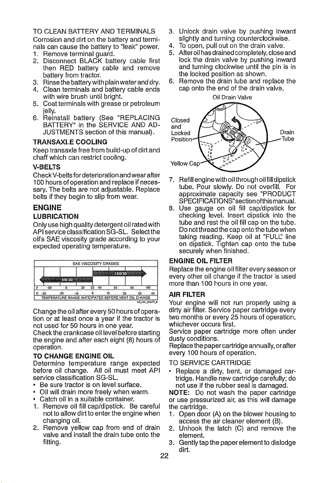
3o Unlock drain valve by pushing inward
slightly and turning counterclockwise.
4. To open, pull out on the drain valve.
5. Aftereil hasdrained completely, close and
lock the drain valve by pushing inward
and turning clockwise until the pin is in
the locked Position as shown.
6. Remove the drain tube and replace the
cap onto the end of the drain valve,
oil Drain Valve
Closed _ _
Locked I _._ _ _ Drain
Position."'_._ .% __ J......_Tube
7. Refill engine with oilthrough oilfill dipstick
tube. Pour slowly. Do not overfill. For
approximate capacity see "PRODUCT
SPECIFICATIONS"section ofthis manual
8. Use gauge on oil fill cap/dipstick for
checking level insert dipstick into the
tube and rest the oil fill cap on the tube.
Do not thread the cap onto the tube when
taking reading. Keep oil at "FULl/' line
on dipstick. Tighten cap onto the tube
securely when finished.
ENGINE OIL FILTER
Replace the engine oil filter every season or
every other oil change if the tractor is used
more than 100 hours in one year.
AIR FILTER
Your engine will not run properly using a
dirty air filter` Service paper cartridge every
two months or every 25 hours of operation,
whichever occurs first.
Service paper cartridge more often under
dusty conditions_
Replace the paper cartridge annually, or after
every 100 hours of operation.
TO SERVICE CARTRIDGE
, Replace a dirty, bent. or damaged car-
tridge. Handle new cartridge carefully; do
not use if the rubber seal is damage&
NOTE; Do not wash the paper cartridge
or use pressurized air. as this wilt damage
the cartridge.
1_ Open door (A) on the blower housing to
access the air cleaner element (B).
2. Unhook the latch (C) and remove the
element.
3. Gently tap the paper elementto dislodge
dirt_
22
Page 23

4. Cleanallaircleanercomponentsofany
accumulateddirt or foreign material,
Prevent any dirt from entering the throat
of carburetor.
5. Install cleaned or new element on the
base and secure with latch.
6. Close and latch the door,
CLEAN AIR SCREEN
Air screen must be kept free of dirt and chaff
to prevent engine damage from overheating,
Clean with a wire brush or compressed airto
remove dirt and stubborn dried gum fibers.
CLEAN AIR INTAKE/COOLING AREAS
To ensure proper cooling, make surethe grass
screen, cooling fins, and other external sur-
faces of the engine are kept clean at all times.
Every 100 hours of operation (more often
under extremely dusty, dirty conditions),
remove the blower housing and other cooling
shrouds. Clean the cooling fins and external
surfaces as necessary. Make sure the cooling
shrouds are reinstalled.
NOTE: Operating the engine with a blocked
grass screen, dirty or plugged cooling fins,
and/or cooling shrouds removed will cause
engine damage due to overheating.
MUFFLER
Inspect and replace corroded muffler and
spark arrester (if equipped) as it could create
a fire hazard and/or damage.
SPARK PLUG(S)
Replace spark plug(s) at the beginning of
each mowing season or after every 100
hours of operation, whichever occurs first.
Spark plug type and gap setting are shown
in "PRODUCT SPECIFICATIONS" section
of this manual.
IN-LINEFUEL FILTER
The fuel filter should be replaced once each
season, If fuel filter becomes clogged, ob-
structing fuel flow to carburetor, replacement
is required.
1o With engine cool, remove filter and plug
fuel line sections°
2, Place new fuel filter in position in fuel line
with arrow pointing towards carburetor.
3o Be sure there are no fuel line leaks and
clamps are properly positioned.
4. Immediately wipe up any spilled gasoline,
Clam___._ amp
Fuel Filter ------__/
CLEANING
, Clean engine, battery, seat, finish, etc.
of all foreign matter.
• Clean debris from steering plate.
Debris can restrict clutch/brake pedal
shaft movement, causing belt slip and
loss of drive.
_, CAUTION: Avoid all pinch points and
movable parts
_.____ Clutch/brake pedaI_o _,_
Clean j °_/_..__. ,,
Steering l
P
_: .... I A(_,_.ei?chI
F_ l_otShown IAr_ PointsI
, Keep finished surfaces and wheels
free of all gasoline, oil, etc_
• Protect painted surfaces with automo-
tive type wax.
We do not recommend using a garden hose
or pressure washer to clean your tractor
unless the engine and transmission are
covered to keep water out. Water in engine
or transmission will shorten the useful life of
your tracton Use compressed air or a leaf
blower to remove grass, leaves and trash
from tractor and mower°
23
Page 24

DECK WASHOUT PORT
'(our tractor's deck is equipped with a
washout port on its surface as part of its
deck wash system+ It should be utilized af-
ter each use.
1+ Drive the tractor to a level, clear spot
on your lawn, near enough to a water
spigot for your garden hose to reach.
IMPORTANT: Make certain the tractor's
discharge chute is directed AWAY from your
house, garage, parked cars, etc+ Remove
bagger chute or mulch cover if attached.
2+ Makesuretheattachmentclutch control
is in the "DISENGAGED" position, set
the parking brake, and stop the engine.
3. Thread the nozzle adapter (packaged
with your tractor's Operator's Manual)
onto the end of your garden hose.
4+ Pull back the lock collar of the nozzle
adapter and push the adapter onto the
deck washout port at the left end of the
mower deck. Release the lock collar to
lock the adapter on the nozzle.
9. Pull back the lock collar of the nozzle
adapter to disconnect the adapter from
the nozzle washout port+
I0+ Move the tractor to a dry area, prefer-
ably a concrete or paved are& Place
the attachment clutch control in the
"ENGAGED" position to remove excess
water and to help dn/before putting the
tractor away,
_WARHING: A broken or missing washout
fitting could expose you or others to thrown
objects from contact with the blade.
• Replace broken or missing washout fitting
immediately, prior to using mower again.
, Plug any holes in mower with bolts and
Iocknuts.
IMPORTANT: Tug hose ensuring connec-
tion is secure.
5+ Turn the water on+
6. While sitting in the operator's position
on the tractor, re+start the engine and
place the throttle lever in the Fast ",,_"
position.
IMPORTANT: Recheck the area making
certain the area is clear.
7. Move the tractor's attachment clutch
control to the "ENGAGED" position.
Remain in the operator's position
with the cutting deck engaged until the
deck is cleaned.
8+ Move the tractor's attachment clutch
control to the "DISENGAGED" posi-
tion. Turn the ignition key to the STOP
position to turn the tractor's engine off.
Turn the water off.
24
Page 25

WARNING: TO AVOID SERIOUS INJURY, BEFORE PERFORMING ANY
SERVICE OR ADJUSTMENTS:
1. Depress clutch/brake pedal fully and set parking brake.
2, Place gearshift lever in neutral position.
3, Place attachment clutch in "DISENGAGED" position,
4. Turn ignition key to "STOP" and remove key,.
5, Make sure the blades and all moving parts have completely stopped.
6o Disconnect spark plug wire from spark plug and place wire where it cannot
come in contact with plugo
TO REMOVE MOWER
1. Place attachment clutch
GAGED" position.
2.
Lower attachment lift lever to its lowest
position.
3,
Disengage belt tension rod (K) from lock
bracket (L).
CAUTION; Belt tension rod is spring
loaded. Have a tight grip on rod and release
slowly.
4. Remove mower belt from electric clutch
pulley (M),
5. Disconnect front link (E) from mower -
remove retainer spring and washer.,
6. Go to either side of mower and disconnect
mower suspension arm (A) from chas-
sis and rear lift link (C) from rear mower
bracket (D) -remove retainer springs and
washers_
7. Go to others!de ofmowerand disconnect
the suspension arm and rear lift link_
in "DISEN-
_h, CAUTION: After rear lift links are discon-
nected, the attachment lift lever will be spring
loaded. Have a tight grip on lift lever when
changing position of the lever.
8, From right side of mower, disconnect
anti-sway bar (S) from right rear mower
bracket (D) - remove retainer spring and
washer and pull mower toward you until
the bar falls from the hole in bracket.
9. Turn tractor steering wheel to the left as
far as it will go,
10oSlide mower out from under right side of
tracton
TO INSTALL MOWER
Follow procedure described in "INSTALL
MOWER AND DRIVE BELT" in the Assembly
section of this manual,
25
Page 26

TO LEVEL MOWER
Make sure tires are properly inflated to the
PSI shown on tires. If tires are over or under
inflated, it may affect the appearance of your
lawn and lead you to think the mower is not
adjusted properly.
VISUAL SIDE-TO-SIDE ADJUSTMENT
1. With al! tires properly inflated and if your
lawn appears unevenly cut, determine
which side of mower is cutting lower.
NOTE: As desired, you can raise the low
side of mower or lower the high side°
2. Go to side of mower you wish to adjust.
3_ With a 3/4" or adjustable wrench, turn
lift link adjustment nut (A) to the left to
lower the mower, or, to the right to raise
the mower_
4. if adjustment is necessary, see steps 2
and 3 in Visual Adjustment instructions
above.
5o Recheck measurements, adjust if neces-
sary until both sides are equal.
FRONT-TO-BACK ADJUSTMENT
IMPORTANT: Deck must be level side-
to-sideo
To obtain the best cutting results, the mower
blades should be adjusted so the front tip is
1/6" to 1/2" lower than the rear tip when the
mower is in its highest position.
,_ CAUTION: Blades are sharF Protect
your hands with gloves and/or wrap blade
with heavy cloth.
• Raise mower to highest position.
• Position any blade so the tip is pointing
straight forward° Measure distance (B) to
the ground at front and rear tip of the blade.
Turn nut rig
to raise mower
NOTE: Each full turn of adjustment nut will
change mower height about 3/16".
4. Test your adjustment by mowing some
uncut grass and visually checking the
appearance. Readjust, if necessary, until
you are satisfied with the results.
PRECISION SIDE-TO-SIDE ADJUSTMENT
1. With alltires properly inflated, park tractor
on level ground or driveway.
•(_ CAUTION: Blades are sharp. Protect
your hands with gloves and/or wrap blade
with heavy cloth.
2. Raise mower to its highest position.
3. At both sides of mower, position blade at
side and measure the distance (A) from
bottom edge of blade to the ground. The
distance should be the same on both sides.
Turn nut left
to Dowermower
• If front t!p of blade is not 1/8" to 1/2" lower
than the rear tip, go to the front of tractor.
• With an 11/16" or adjustable wrench,
loosen jam nut A several turns to clear
adjustment nut B.
• With a 3/4" or adjustable wrench, turn
front link adjustment nut (B) clockwise
(Itighten) to raise the front of mower, or,
counterclockwise (loosen) to lower the
front mower.
Tighten adjust nut
B to raise mower
Loosen jam nut A first
NOTE: Each full turn of the adjustment nut
will change mower height about 1/8".
° Recheck measurements, adjust if neces-
sary until front tip of blade is 1/8" to t/2"
lower than the rear tip.
° Hold adjustment nut in position with wrench
and tighten jam nut securely against ad-
justment nut.
Loosen adjust
nut B to lower
26
mower
Page 27

TO REPLACE MOWER DRIVE BELT
MOWER DRIVE BELT REMOVAL
I, Park tractor on a level surface, Engage
parking brake,
2, Lower attachment lift lever to its lowest
position.
3, Disengage belt tension rod (K) from lock
bCracket (L),
AUTION: Belt tension rod is spring load-
ed, Have afirm grip on rod and release slowly,
4, Remove screws (P) from Roll, and L.H.
mandrel covers and remove covers (Q) o
5. Remove any dirt or grass clippings which
may have accumulated around mandrels
and entire upper deck surface°
6. Remove belt from electric clutch pulley
(M), both mandrel pulleys (R) and all idler
pulleys (S).
MOWER DRIVE BELT INSTALLATION
1_ Install belt around both mandrel pulleys
(R) and around idler pulleys (S) as shown.
2. Install belt onto electric clutch pulley (M).
IMPORTANT: Check belt for proper routing
in all mower pulley grooves_
3. Reassemble R.H. and L.H. mandrel cov-
ers (Q). Securely tighten all screws.
4. Engage belt tension rod (K) on locking
bracket (L).
CAUTION: Belt tension rod is spring load-
ed, Have atight grip on rod and engage slowly,
5. Raise attachment lift lever to highest
position,
BELT REMOVAL-
t. Remove mower (See "TO REMOVE
MOWER" in this section of manual).
NOTE: Observe entire motion drive belt
and position of all belt guides and keepers°
2. Disconnect clutch wire harness (A).
3_ Remove anti-rotation link (B) on right
side of tractor.
4. Remove belt from stationary idler (C)
and clutching idler (D).
5. Remove belt from centerspan idler (E).
6. Pull belt slack toward rear of tractor.
Remove belt upwards from transaxle
input pulley (F)_
7. Remove belt downward from engine
pulley and around electric clutch (G).
8. Slide belt toward rear of tractor, off the
steering plate (H) and remove from tractor.
BELT INSTALLATION -
1. Install new belt from tractor rear to
front, over the steering plate (H) and
above clutch brake pedal shaft (J).
2. Pull belt toward front of tractor and roll
belt around electric clutch and onto
engine pulley (G)o
3. Pull belt toward rear of tractor° Care-
fully work belt down around transaxle
input pulley (F)o Be sure belt is inside
the belt keeper.
4. Install belt on centerspan idler (E)o
5. Install belt through stationary idler (C)
and clutching idler (D).
6_ Reinstall anti-rotation link (B) on right
side of tractor. Tighten securely.
7o Reconnect clutch harness (A)_
8. Make sure belt is in all pulley grooves
and inside all belt guides and keepers.
9. Install mower (See "TO INSTALL
MOWER" in this section of manual).
I
TO REPLACE MOTION DRIVE BELT
Park the tractor on level surface. Engage
parking brake. For assistance, there is a
belt installation guide decal on bottom side
of left footrest.
27
Page 28

TRANSAXLE GEAR SHIFT LEVER NEU-
TRAL ADJUSTMENT
The transaxle should be in neutral when the
gear shift lever is in neutral (N) (lock gate)
position, The adjustment is preset at the
factory; however, if adjustment is needed,
proceed as follows:
1, Make sure transaxle is in neutral (N),
NOTE: When the tractor rear wheels move
freely, the transaxle is in neutral
2, Loosen adjustment bolt in front of the
right rear wheel.
3, Position the gear shift lever in the neutral
(N) position,
4. Tighten adjustment bolt securely.
NOTE: If additional clearance is needed to
get to adjustment bolt, move mower deck
height to the lowest position.
Gearshift Adjustment Bolt
Lever
,,.,_ :ral
/ _,__ '! Lock Gate
TO REMOVE WHEEL FOR REPAIRS
i. Block up axle securely_
2. Remove axle cover, retaining ring and
washers to allow wheel removal (rear
wheels have a square key - Do not Iose)_
3. Repair tire and reassemble.
NOTE: On rear wheels only: align grooves in
rear wheel hub and axle. Insert square key.
4. Reptacewashers and snap retaining ring
securely in axle groove,
5. Replace axle cover.
NOTE: To seal tire punctures and prevent
flat tires due to slow leaks, purchase and
use tire sealant from Sears. Tire sealant also
prevents tire dry rot and corrosion,
Washers
Retaining
Axle
Cover
TO CHECK BRAKE
tf tractor requires more than five (5) feet to
stop at highest speed in highest gear on a
level, dry concrete or paved surface, then
brake must be serviced.
You may also check brake by:
!. Parktractoron alevel, dryconcreteor paved
surface, depress clutch/brake pedal all
the way down and engage parking brake.
2. Place gear shift lever in neutral position.
The rear wheels must lock and skid when
you try to manually push the tractor forward.
If the rear wheels rotate, then the brake
needs to be serviced. Contact a Sears or
other qualified service center.
TO START ENGINE WITH A WEAK BAT-
TERY
_IbWARNING: Lead-acid batteries gener-
ate explosive gases_ Keep sparks, flame
and smoking materials away from batteries.
Always wear eye protection when around
batteries,
Ifyour battery is too weak to start the engine, it
should be recharged. (See "BATTERY" in the
MAINTENANCE section of this manual).
if "jumper cables" are used for emergency
starting, follow this procedure:
IMPORTANT: Your tractor is equipped with
a 12 volt system, The other vehicle must also
be a i 2 volt system_ Do not use your tractor
battery to start other vehicles°
TO ATTACH JUMPER CABLES
I. Connect one end ofthe RED cable to the
POSITIVE (+) terminal of each battery(A-
B), taking care notto short against tractor
chassis.
2. Connect one end of the BLACK cable
to the NEGATIVE (_) terminal (C) of fully
charged battery.
3. Connect the other end of the BLACK
cable (D) to good chassis ground, away
from fuel tank and battery.
TO REMOVE CABLES, REVERSE
ORDER
I. BLACK cable first from chassis and then
from the fully charged battery.
2. RED cable last from both batteries.
Square
Key ly.
(Rear Wheel Only) -='_-
Weak or Dead Fully Charged
Battery Battery
28
Page 29

REPLACING BATTERY
,_WARNING: Do notshort battery terminals
by allowing a wrench or any other object to
contact both terminals at the same time.
Before connecting battery, remove metal
bracelets, wristwatch bands, rings, etc,
Positive terminal must be connected first to
prevent sparking from accidental grounding.
1. Lift hood to raised position.
2o Disconnect BLACK battery cable (A)then
RED battery cable and carefully remove
battery from tractor.
3. Install new battery with terminals in same
position as old battery.
4. First connect RED battery cable (B) to
positive (+) battery terminal with hex bolt
and keps nut as shown. Tighten secu rely.
Slide terminal cover (C) over terminal
5. ConnectBLACKgrounding cableto neg-
ative (-) battery terminal with remaining
hex bolt and keps nut. Tighten securely.
6. Close hood.
_ Negative
(Black)
Cable
TO REPLACE HEADLIGHT BULB
I. Raise hood.
2. Remove bulb holder from the hole in the
backside of the grill.
3. Replace bulb in holder and install bulb
holder securely back into the hole in the
backside of the grill.
4. Close hood.
TO REMOVE HOOD & GRILL ASSEMBLY
1. Raise hood.
2. Unsnap headlight wire connector.
3o Stand in front of tractor. Grasp hood at
sides, tilt toward engine and lift off of
tractor.
4. When replacing hood, be sure to recon-
nect the headlight wire connector.
Hood
Headlight Wire
Connector
Positive
(Red)
Cable
FRONT WHEEL TOE-IN/CAMBER
'(our new tractor front wheel toe-in and cam-
ber is set at the factory and is normal. The
front wheel toe-in and camber are not adjust-
ableo If damage has occurred to affect the
factory set front wheel toe-in or camber, con-
tact a Sears or other qualified service center.
INTERLOCKS AND RELAYS
Loose or damaged wiring may cause your
tractor to run poorly, stop running, or prevent
it from starting.
• Check wiring.
TO REPLACE FUSE
Replace with 30 amp automotive-type plug-
in fuse° The fuse holder is located behind
the dash.
p,
ENGINE
Maintenance, repair, or replacement of the
emission control devices and systems, which
are being done at the customers expense,
may be performed by any non-road engine
repair establishment or individual Warranty
repairs must be performed by an authorized
engine manufacturer's service outlet,
CARBURETOR
If your engine does not operate properly due
to suspected carburetor problems, take your
tractor to a Sears or other qualified service
center for repair and/or adjustment.
High speed stop is factory adjusted. Do not
adjust - damage may result.
IMPORTANT: Never tamper with the engine
governor, which is factory set for proper
engine speed_ Overspeeding the engine
above the factory high speed setting can be
dangerous. If you think the engine-governed
high speed needs adjusting, contact aSears
or other qualified service center,, which has
proper equipment and experience to make
any necessary adjustments°
29
Page 30

Immediately prepare your tractor for storage
at the end of the season or if the tractor will
t be used for 30 days or more°
WARNING: Never store the tractor with
gasoline in the tank inside a building where
fumes may reach an open flame or spark.
Allow the engine to cool before storing in
any enclosure_
TRACTOR
Remove mower from tractor for winter
storage, When mower is to be stored for a
period of time, clean it thoroughly, remove
all dirt, grease, leaves, etc° Store in a clean,
dry area.
1. Clean entire tractor (See "CLEANING"
in the Maintenance section of this
manual).
2. Inspect and replace belts, if necessary
(See belt replacement instructions in the
Service and Adjustments section of this
manual).
3. Lubricate as shown in the Maintenance
section of this manual.
4. Be sure that all nuts, bolts and screws
are securely fastened° Inspect moving
parts for damage, breakage and wear.
Replace if necessary.
5. Touch up all rusted or chipped paint
surfaces; sand lightly before painting.
BATTERY
• Fully charge the battery for storage.
• After a period of time in storage, battery
may require recharging.
, To help prevent corrosion and power
leakage during long periods of storage,
battery cables should be disconnected
and battery cleaned thoroughly (see "TO
CLEAN BATTERY AND TERMINALS" in
the Maintenance section of this manual).
, After cleaning, leave cables disconnected
and place cables where they cannot come
in contact with batter,/terminals.
• If battery is removed from tractor for
storage, do not store battery directly on
concrete or damp surfaces.
ENGINE
FUEL SYSTEM
IMPORTANT: It is important to prevent
gum deposits from forming in essential fuel
system parts such as carburetor, fuel hose,
or tank during storage. Also, alcohol blended
fuels (called gasohol or using ethanol or
methanol) can attract moisture which leads
to separation and formation of acids during
storage. Acidic gas can damage the fuel
system of an engine while in storage.
° Empty the fueltank by starting the engine
and letting it run until the fuel lines and
carburetor are empty.
• Never use engine or carburetor cleaner
products in the fuel tank or permanent
damage may occur.
• Use fresh fuel next season.
NOTE: Fuel stabilizer is an acceptable
alternative in minimizing the formation of
fuel gum deposits during storage. Add
stabilizer to gasoline in fuel tank or storage
container. Always follow the mix ratio found
on stabilizer container. Run engine at least
10 minutes after adding stabilizer to allow
the stabilizer to reach the carburetor. Do not
empty the gas tank and carburetor if using
fuel stabilizer.
ENGINE OIL
Drain oil (with engine warm.) and replace
with clean engine oil. (See "ENGINE" in the
Maintenance section of this manual)_
CYLINDER(S)
1. Remove spark plug(s)_
2. Pourone ounce ofoil through spark plug
hole(s) into cylinder(s).
3. Turn ignition key to start position for a
few seconds to distribute oil.
4. Replace with new spark plug(s).
OTHER
• Do not store gasoline from one season to
another.
, Replace your gasoline can if your can
starts to rust. Rust and/or dirt in your
gasoline will cause problems.
, If possible, store your tractor indoors and
cover itto give protection from dust and dirt.
• Cover your tractor with a suitable protec-
tive cover that does not retain moisture.
Do not use plastic_ Plastic cannot breathe
which allows condensation to form and
will cause your tractor to rusL
IMPORTANT: Never cover tractor while
engine and exhaust areas are still warm.
3O
Page 31

TROUBLESHOOTING CHART:
See appropriate section in manual unless directed to Sears service center
.........................!............] .................- -- c°""'CT!°"
Will not start 1 Out of fuel,, 1 Fill fuel tank.
Hard to start
2 Engine not "CHOKED" properly, 2 See "TO START ENGINE" in
3 Engine flooded. 3 Wait several minutes before
4 Bad spark plugo 4 Replace spark plug.
5 Dirty air filter_ 5 Clean/replace air filter_
6 Dirty fuel filter,, 6 Replace fue! filter.
7 Water infuel. 7 Empty fuel tank and carburetor,
8 Loose or damaged wiring,, 8 Check atl wiring,
9 Carburetor out of adjustment, 9 Sea"To Adjust Carburetor" in
i10 Engine valves out of adjustment. 10 Contact a Sears or other qualified
1 Dirty air filter.,
2 Bad spark plugo
3 Weak or dead battery.
4 Dirty fuel filter.
5 Stale or dirty fuel.
6 Loose or damaged wiring.
Operation section,
attempting to start,,
refill tank with fresh gasoline and
replace fuel filter.,
Service and Adjustments section.
service center,
1 Clean!replace air filter.
2 Replace spark plugo
3 Recharge or replace battery
4 Replace fuel fi_ter_
5 Empty fuel tank and refill tank witt_
fresh, clean gasoline.
6 Check allwiring_
Engine will not 1
turn over
7 Carburetor out of adjustment.
8 Engine valves out of adjuslmenL
Clutch/brake pedal not depressed.
2
Attachment clutch ts engaged.
3
Weak or dead battery_
4
Blown fuse,
5
Corroded battery terminals.,
6
Loose or damaged wiring.
7
Faulty ignition switch_
8
Faulty sotenoid or starter.
9
Faulty operator presence
switch(es),
31
7 See "To Adjust Carburetor" in
Service and Adjustments section.
8 Contact a Sears or other qualified
service center.
m_
1 Depress clutch/brake pedal,
2 Disengage attachment clutch.
3 Recharge or replace battery°
4 Replace fuse.
5 Clean battery terminals.
6 Check altwiring_
7 Check!replace ignition switch.
8 Check/replace solenoid or starter°
9 Contact a Sears or other qualified
service center.
Page 32

TROUBLESHOOTING CHART:
See appropriate section in manual unless directed to Sears service center
PROBLEM
Engine clicks but
will not start
Loss of power
Excessive vibration
CAUSE
1
Weak ordead battery+
2
Corroded battery terminals_
3
Loose or damaged wiring+
4
Faulty solenoid or starter+
1
Cutting too much grass/too fast.
2
Throttle in "CHOKE" position.
3
Build-up of grass, leaves and
trash under mower,.
4
Didy air filter,,
5
Low oil level/dirty oil,.
6
Faulty spark plug,
7
Dirty fuel filter°
8
Stale or dirty fuel.
9
Water in fuel+
10
Spark plug wire loose.
11
Dirty engine air screen/fins+
12
Dirty/clogged muffler.
13
Loose or damaged wiring+
14
Carburetor out of adjustment,
15
Engine valves out of adjustment,,
1
Worn, bent or loose blade.
2
Bent blade mandrel.
CORRECTION
1
Recharge or replace battery.
2
Clean battery terminals°
3
Check all wiring.
4
Check/replace solenoid or starter.,
1
Raise cutting height/reduce
speed+
2
Adjust throttle control.
3
Clean underside of mower
housing_
4
Clean/replace air filter+
5
Check oil level/change oil.,
6
Clean and regap or change spark
plug,
7
Replace fuel filter.
B
Empty fuel tank and refill tank with
fresh, clean gasoline,,
9
Empty fuel tank and carburetor,
refill tank with fresh gasoline and
replace fuel filter.
10
Connect and tighten spark plug
wire,
11
Clean engine air screen/fins_
12
Clean/replace muffler.
13
Check all wiring_
14
See "To Adjust Carburetor" in
Service and Adjustments sectiom
15
Contact a Sears or other qualified
service center.
1
Replace blade_ Tighten blade bolt.!
2
Contact a Sears or other
Engine continues to
run when operator
leaves seat with
attachment clutch
engaged
3
Loose/damaged part(s)+
1
Faulty operator-safety presence
control system°
32
qualified service center,
3
Tighten loose part(s).
Replace damaged parts.
+
1
Check wiring, switches and
connections, If not corrected,
contact a Sears or other
Page 33

TROUBLESHOOTING CHART:
See appropriate section in manual unless directed to Sears service center
IPROBLEM CAUSE
Poor cut - uneven 1
cutting 2
Worn, bent or loose blade,
Mower deck not level,,
3
Buildup of grass, leaves, and
trash under mower.
4
Bent blade mandrel,
Clogged mower deck vent from
build-up of grass, leaves, and
trash around mandrels,,
Mower blades will 1 Obstruction in clutch mechanism.. 1
not rotate
2 Worn/damaged mower drive belt, 2
3 Frozen idler pulley 3
4 Frozen blade mandrel 4
Poor grass 1 Engine speed too slow., 1
discharge
2 Travel speed too fast, 2
3 Wet grass. 3
4 Mower deck not level 4
CORRECTION
1 Replace blade. Tighten blade bolto
2 Level mower deck.
3 Clean underside of mower
housing_
4 Contact a Sears or other
qualified service center.
5 Clean around mandrels to
open vent holes.
Remove obstruction,,
Replace mower drive bell
Replace idler pulley,,
Contact a Sears or other
qualified service center.
Place throttle control in "FAST"
position,,
Shift to slower speed,
Allow grass to dry before mowing,
Level mower deck°
Headlight(s) not
working
(if so equipped)
5 Low/uneven tire air pressure. 5
6 Worn, bent or loose blade. 6
7 Buildup of grass, leaves and 7
trash under mower.
8 Mower drive belt worn,, 8
9 Blades improperly installed, 9
10 Improper blades used, 10
1'1 Clogged mower deck vent holes 11
from buildup of grass, leaves, and
trash around mandrels.
1 Light switch is "OFF".
2 Bulb(s) or lamp(s) burned out.
3 Faulty light switch_
4 Loose or damaged wiring.
5 Blown fuse,
Check tires for proper PSt_
Replace/sharpen blade° Tighten
blade bolt,
Clean underside of mower
housing,
Replace mower drive bell
Reinstall blades sharp edge down,
Replace with blades listed in
this manual,,
Clean around mandrels to
open vent holes.
1 Turn light switch "ON"_
2 Replace bulb(s) or lamp(s),
3 Check/replace light switch°
4 Check wiring and connections°
5 Replace fuse_
33
Page 34

TROUBLESHOOTING CHART:
See appropriate section in manual unless directed to Sears service center
PROBLEM
CAUSE CORRECTION
Battery will not 1
charge 2
...... .
Loss of drive 1
Engine "backfires"
when turning
engine "OFF"
Poor cable connections. ! 2 I Checklclean all connections_
3
Fault,] regulator (if so equipped) ! 3 I Replace regulator
Faulty alternator_ ! 4 I Replace allernator_
Debris on steering plate (if 1 See "CLEANING" in the
equipped), maintenance section,
2
Motion drive belt worn, damaged, 2 Replace motion drive belt,
or broken.
3
Axle key missing. 3 Install axle key at rear wheel, See
t Engine throttle control not sel 1
between half and ful! speed (fast)
position before stopping engine
Engine dies when 1 Reverse operation system (ROS) I
tractor is shifted is not "ON" while mower or other
into reverse
attachment is engaged,
1 I
! |
"TO REMOVE WHEEL" in the
Service and Adjustments section,
Move throttle control between
half and ful! speed (fast) position
before stopping engine,
Turn ignition key to ROS "ON"
position, See Operation section°
NEED MORE HELP?
You'll find the answer and more on managerayhome.com -, for free!
- Find this and a[t your other product manuats on[ineo
, Get answers from our team of home experts.
, Get a personalized maintenance plan for your home.
• Find _nformation and toots to hel.pw_th home projects.
manage home
brought to youby Seam
34
I;'::
.=
Page 35

/
/
/
!
i
I
I
/
/
m
O_
-4
m
0
C
0
m
/
Oo
-4
m
Z
0
O0
0
"0
m
/
/
!
I
/
/
/
/
/
o_
0
Oo
"rl
m
0
"0
m
:o
35
m
0
z
Page 36

Garantia .................................................................36
Reglas de Seguridad ..........................................37
Especificaciones del Producto ..............................40
MontajeiPre Operaci6n ..................................... 41
Operaci6n ..................................................................47
Mantenimiento .................................................. 54
GARANTiA COMPLETA DE CRAFTSMAN
DOS AI;tOS PARA EL EQUIPO TRACTOR
Cuando se opera y mantiene de acuerdo con todas las instrucciones que se suministran, si este
equipo tractor falla debido a un defecto de material omano de obra dentro de los dos a5os posteriores
a la fecha de compra, tlame al tel_fono 1-800-4-MY-HOME® para solicitar la reparaciSn gratuitao
Adem&s, cuando se opera y mantiene de acuerdo con todas las instrucciones que se suministran,
la garantia tambi6n cubre defectos de material y mano de obra del bastidor y de[ eje delantero por
cinco aSos a partir de la fecha de compra.
Programa de Mantenimiento ..............................54
Servicio y Ajustes ........................................... 59
Almacenamiento ..............................................................64
Identificaci6n de Problemas .................................65
Servicio Sears .........................................Contratapa
Esta garantia cubre UNICAMENTE defectos de material y mano de obra. Sears NO
pagara:
. Componentes de desgaste que se desgasten durante el uso normal, incluso (pero sin limitarse
a elto) hojas, bujias, filtros de aire, correas y filtros de aceite.
• Servicios de mantenimiento est#.ndar, cambios de aceite o afinaciones.
• Reemplazo o reparaci6n de neum#,ticos por pinchazos causados por objetos externos como
clavos, espinas, tocones o vidrioso
• Reemplazo o reparaci0n de neum#.ticos o ruedas por el desgaste normal, accidentes o por
operaciSn o mantenimiento incorrectos..
• Reparaciones necesarias por abuso del operador, incluso (pero sin limitarse aetlo) daSos causados
por remolcar objetos que superen la capacidad del equipo tractor, chocar contra objetos que
deblen el bastidor o el cigQeSal o por sobrepasar la velocidad del motor.
• Reparaciones necesarias por negligencia del operador, incluso (pero sin limitarse a etlo) daSos
el_ctricos y mec&nicos causados per el almacenamiento incorrecto, pot no usar el grado y la
cantidad correctos de aceite de motor, por no mantener del muelle libre de residuos inflamables
o por no mantener el equipo tractor de acuerdo con las instrucciones que contiene el manual del
operadoro
• Limpieza o reparaciones dei motor (sistema de combustible) cuando se determina que se us6
combustible contaminado y oxidado (sarro). En general, el combustible debe usarse dentro de
los 30 dias posteriores a su compra.
• Deterioro y desgaste normal de los acabados exteriores o sustituci6n de r6tulos de productos.
Toda cobertura de garantia del equipo tractor y la bateria queda nula si este producto se utiliza
alguna vez con fines comerciales o de alquiler.
Esta garantia se aplica s6Io mientras el producto se encuentre dentro de los EEolJU,,
Esta garantia le otorga derechos legales especificos, y usted tambi6n puede tener otros derechos
que varfan de un estado a otro_
Sears, Roebuck and Co., Hoffman Estates, IL 60179
36
Page 37

_PELIGRO: Esta Maquina cortadora es capaz de amputar las manosy los pies y de lanzar
objetos, si no se observan las instrucciones de seguridad siguientes se pueden produclr
lesiones graves o ta muerte.
_DVERTENCIA: Siempre desconecte el alam-
bre de la bujia y p6ngalo donde no pueda entrar
en contacto con la bujia, para evitar el arranque
por accidente, durante la preparaci6n, el trans-
porte, el ajuste o cuando se hacen reparaciones_
_DVERTENCIA: Noavance cuesta abajo a pun-
to muerto ya que podria perder el control del tractor°
_ADVERTENClA: Remolque solamente los
accesorios recomendados y conformes a las
caracteristicas indicadas por el fabricante de su
tractor. Tenga cuidado y prudencia al utilizar el
tractor. Cuando se encuentre en un declive, oper
utilizando exclusivamente lavelocidad m&sbajao
En caso de un declive una carga excesiva podria
resultar peligrosao Los neum_ticos pueden
perder la tracci6n con el suelo y hacerle perder
et control de su tractor.
,_ADVERTENCIA" El tubo de escape del motor,
algunos de sus constituyentes y algunos com-
ponentes del vehiculo contienen o desprenden
productos qufmicos conocidos en el Estado de
California como causa de c,_ncer y defectos al
nacimiento u otros dafios reproductivos_
_I_kDVERTENCIA: Los bornes, terminales y ac-
cesorios relativos de la baterJa contienen plomo
o compuestos de plomo, productos quimicos
conocidos enel Estado de California como causa
de c_ncer y defectos al nacimiento u otros dafios
reproductivos, Lavar las manos despu_s de
manipularlos.
I. FUNCIONAMIENTO GENERAL
• Leer, entender y seguir todas las instrucciones
sobre la m&quina yen el manual antes de
empezar_
• No poner las manos o los pies cerca de parIes
giratorias o debajo de ta m_,quinaomantener
siempre limpia la abertura de descarga.
• Permitir el funcionamiento de la m&quina s61o
a adultos que tengan familiaridad con las
instrucciones.
• Limpiar el &rea de objetos como piedras,
juguetes, cables, etc. que pueden ser recogi-
dos y disparados con las cuchillas,,
• Asegurarse de que el &rea est6 libre de otras
personas antes de ponerla en marcha. Parar
la m#.quina si alguien entra en el &rea,
• Nunca Ilevar pasajeros.
. No cortar marcha atr&s al no ser absolu-
tamente necesarioo Mirar siempre abajo y
defante mientras se procede atr&s.
, Nunca dirigir el material descargado hacia ha-
die, Evitar descargar material contra paredes
u obstruccioneso El material podria rebotar
hacia el operador. Parar las cuchitlas cuando
se pasan superficies de gravao
• No maneje la m&quina si no tiene la trampa
para c_sped completa, ta canaleta de descarga
u otros dispositivos de seguridad en su lugar
yen funcionamientoo
• Ralentizar antes de giraro
. Nunca dejar una m&quina encendida sin vigi-
lancia. Apagar siempre las cuchillas, porter et
freno de estacionamiento, parar el motor, y
quitar las Ilaves antes de bajar.
• Desenganche las hojas cuando no est6
cortando c_spedo Apague el motor y espere
hasta que todas tas partes se detengan por
completo antes de limpiar la m&quina, retirar
ta trampa para c_sped o destapar la canaleta
de descarga.
• Hacer funcionar la m&quina s61ocon ia tuz del
dia o luz artificial buena,,
. No hacer funcionar la m&quina estando bajo
los efectos de alcohol o droga.
. Porter atenci6n al tr&fico cuando se opera
cerca de calles o se cruzano
• Poner la m&_ima atenci6n al cargar o descar-
gar ta m&quina en una caravana o cami6n.
• LIevar siempre galas de protecciSn cuando se
hace funcionar la m&quina,
• Los datos indican que los operadores a partir
de los 60 afios est&n afectados por un gran
porcentaje de heridas retativas a ia conducci6n
del cortac_sped, Estos operadores tendrJan
que evaluar su habilidad de hacer funcionar
el cortac6sped de modo Io bastante seguro
para proteger a si mismos y a otras personas
de heridas graves.
• Seguir las recomendaciones del fabricante
para los pesos y contrapesos de las ruedas.
. Mantener la m&quina libre de hierba, hojas
u otros escombros que pueden tocar el
tubo de escape / partes del motor calientes
y quemarse. No permitir que el puente det
cortac_sped cargue hojas u otros residuos
que pueden causar acumulaciones. Limpiar
toda salpicadura de aceite o carburante antes
de hacer operaciones sobre la m&quina o
guardarla. Dejarla enfriar antes de guardada.
!!. FUNClONAMIENTO EN PENDIENTES
Las pendientes son el mayor factor de acci-
dentes relativos a la p_rdida de control y vuelco,
que pueden causar severas heridas o muerte.
El funcionamiento en pendientes requiere una
atenci6n extra_ Si no es posible hacer marcha
atr,_sen una pendiente o si te sientes incomodo,
no la cortes.
. Cortar hacia arriba y abajo de una pendiente,
no de modo horizontal,,
• Poner atenciones a los hoyos, las raices, los
bultos, las piedras u otros objetos escondidos.
EI terreno irregular puede volcar la m&quina,
La hierba alta puede esconder obst&culos.,
37
Page 38

• Escogerunavelocidaddemarchabajade
modequenoseanecesariopararseocambiar
estandoenunapendiente°
• Nocortartahierbamojada.Lasruedaspueden
perdertracciSno
Ponersiempreunamarchacuandoseest#,
enpendientes_Noponerenpuntomuertoe ir
cuesta abajo.
• Evitar arrancar, pararse o girar en una pendi-
ente_Si las ruedas pierden tracci6n, desconec-
tar las cuchillas y preceder despacio cuesta
abajo en la pendiente.
, Mantener todo los movimientos en las pen-
dientes tentos y gradual. No hacer cambies
repentinos de vetocidad o direcci6n, ya que
pueden causar el escape de la m&quina°
• Poner la m&_ima atenci6n cuando la m&quina
funciona con captadores de hierba u otros
dispositivos enganchados; pueden afectar la
estabilidad de la m&quina. No usar en pendi-
entes empinados,
• No intentar estabitizar lam&quina poniendo el
pie en el terreno.
, No cedar cerca de bajadas, cunetas y oriltas.
Las m&quina puede volcarse improvisamente
si una rueda est& en el borde o se hunde.
III, NII_IOS
Si el operador no pone atenciSn a la presencia
de los nifios pueden ocurrir accidentes tr_gicos.
Los nifios a menudo est&n atraidos per la m&qui-
nay fas actividad de co[tar. No dar per hecho
de que los nifios se queden adonde estaban la
t_itimavez que los visteso
• Mantener los nifios fuera del &rea de corte y
vigilados per un adulto responsable que no sea
el operador,
• Estar alerta y apagar la m&quina si un niSos
entra en el &reao
• Antes y durante la marcha air&s, mirar adelante
y abajo para ver si hay nifios pequefios.
• Nunca llevar nifios, incluso si hay las cucl3illas
apagadas. Poddan caer y herirse seriamente
o intefferir con et funcionamiento seguro de la
m&quina, los nifios que se hart Ilevado prec-
edentemente pueden aparecer de pronto en el
&rea de corte per otto paseo y ser atropellados
o tumbados per la m&quinao
, Nunca dejar que los nifios manipulen la
m_,quina.
• Tener el m#,ximo cuidado cuando se acerca a
cantos ciegos, arbustos, &rboles u otros obje-
tos que pueden impedir la vista de niflos.
IV. REMOLQUE
• Remolcar s6Io con una m&quina que tenga un
gancho disefiado para remolcar,, Enganchar el
equipo o remotcar s61o en el punto dispuesto
al efecto.
• Seguir las recomendaciones del productor con
respecto a los limites del equipo per remelcar
y el remolque en pendientes.
• Nunca permitir que nifios u otras personas
est_n dentro del equipo per remotcar.
• En pendientes, el peso del equipo remolcado
puede causar la p6rdida de tracci6n y la p6r-
dida de control,
• Viajar despacio y dejar m&s distancia para
frenar.
V. SERVlClO
MANIPULAOION SEGURA DE LA GASOLINA
Para evitar heridas personales o dafios a las
cosas, poner el m#,ximo cuidado a la hera de ma-
nipular la gasolina, La gasolina es extremamente
inflamable y los vapores son explosives.
• Apagar todos los cigarrillos, cigarros, pipas y
otras fuentes de ignici6n.
, Usar s61ocontenedores para gasolina aproba-
dos°
, Nunca quitar el tap6n de la gasolina o afiadir
carburante con et motor en marcha, dejar
enfriar el motor antes del abastecimiento de
la gasolina.
• Nunca abastecer la m&quina al interiorde un
local.
• Nunca guardar la m&quina o el contenedor
de! carburante deride haya una llama abierta,
chispas o una luz piloto come un calentador
de agua u otros dispositivos.
• Nunca Ilenar los contenedores al interior de
un vehiculo o en una caravana o cami6n
recubiertos con un forro de pl&sticm Colocar
siempre los contenedores en el terreno lejos
del vehiculo cuando se est,_Ilenando.
, Quitar el equipo de gas del cami6n o caravana
y abastecerlo en el terreno. Si no es posible,
abastecer dicho equipo con un contenedor por-
t&til, m&s bien que de un surtidor de gasolina.
• Mantener la boquilla a contacto del borde
del dep6sito de carburante o la abertura del
contenedor durante toda la operaci6n de
abastecimiento, No utilizar un dispositivo con
boquilla cerrada-abierta..
• Si se vierte carburante sobre la ropa, cambi-
arse fa ropa inmediatamente.
, Nunca Ilenar et dep6sito mrs de Io debido_
Volver a colocar el tap6n del gas y cerrar de
mode firme.,
OPERACIONES DE SERVICIO GENERALES
• Nunca hacer funcionar ta m_quina en un _rea
cerrada.
, Mantener todas las tuercas y pernos apretados
para asegurarse de que trabaja en condiciones
seguraso
, Nunca modificar los dispositivos de seguridad.
Controlar su correcto funcionamiento regular-
mente.
38
Page 39

o Mantener la m&quina libre de hierba, hojas
u otros residuos acumulados_ Limpiar las
salpicaduras de aceite o carburante y quitar
cualquier cosa mojada con carburante. Dejar
que la m_quina se enfrle antes de guardarla,
• Si se golpea un objeto ajeno, hay que pararse
e inspeccionar ta m_.quina. Reparar, si es nec-
esario, antes de votver a poner en marcha.
• Nunca hacer ningQn ajuste o reparaciSn con
el motor en funci6m
• Verifique los componentes de la trampa para
c_sped y la canaleta de descarga con frecuen-
ciay sustituya con repuestos recomendados
por el fabricante cuando sea necesario.
• Las cuchillas del cortac6sped son afiladas,
Envolver la cuchilta, ponerse guantes y poner
la m_txima atenci6n cuando se hacen opera-
clones en elias.
• Controlar el funcionamiento del freno frecuent-
emente. Ajustar y hacer las operaciones de
mantenimiento cuando eso sea necesario°
, Mantener y sustituir las etiquetas de seguridad
e instrucciSn, cuando sea necesario.
• Asegurarse de que el &tea est_ libre de otras
personas antes de ponerla en marcha, para la
m&quina si alguien entra en et &rea,
• Nunca Ilevar pasajeros.
. Nocortar marcha atr&s al no set absolutamente
necesario_ Mirar siempre abajo y delante
mientras se procede atr&s_
• Nunca Ilevar niSos, incluso si hay las cuchillas
apagadas. Podrian caer y hefirse seriamente
o interferir con el funcionamiento seguro de la
m&quina, los ni_os que se han ilevado prec-
edentemente pueden aparecer de pronto en et
_rea de corte por otro paseo y ser atropellados
o tumbados per ia m&quina_
• Mantener los nitros fuera del &rea de corte y
vigilados por un adulto responsable que nosea
el operador,
° Estar alerta y apagar la m&quina si un niSos
entra en el &rea,,
• Antes y durante la marcha atr&s, mirar adelante
y abajo para ver si hay niSos pequeSos,
• Cortar hacia arriba y abajo de una pendiente
(15° M&x), no de modo horizontal.
, Escoger una velocidad de marcha baja de
modo que no sea necesario pararse o cambiar
estando en una pendienteo
• Evitar arrancar, pararse o girar en una pendi-
ente. Si las ruedas pierden tracciSn, desconec-
tar las cuchillas y proceder despacio cuesta
abajo en la pendiente,
• Si la m&quina se para mientras va cuesta
arriba, desconectar las cuchillas, poner fa
marcha atr&s y ir hacia atr&s despacio.
• No girar estando en pendientes si no es nec-
esario, y luego girar despacio y gradualmente
cuesta abajo, si es posible.
39
Page 40

ESPECIFICACIONES DEL PRODUCTO
Capacidad y Tipo
de gasolina:
Tipo de Aceite:
(API-SG-SL)
Capacidad de
Aceite:
BujJa:
Vefocidad de
Recarrido
(MPH/KPH):
Sistema de Carga: 15 Amps @3600 RPM
Bateria: AmpiHr: 28
Torsi6n del
Perno de la Cuchilla: 45.55 Ft. Lbso
FELIOITACIONES por la compra de su tractorr
Ha sido diseBado, planificado y fabricado para
darle tamejor confiabilidad y el mejor rendimiento
posibte.
En el caso de que se encuentre con cualquier
problema que no pueda solucionar f&cilmente,
haga et favor de ponerse en contacto con un
centro de servicio Sears o con un otro centro de
servicio cualificadoo Cuenta con t#cnicos bien
capacitados y competentes y con las herramien-
tas adecuadas para darle servicio o para reparar
este tractor,
Haga el favor de leer y de guardar este manual°
Estas instruc-ciones le permitir&n montar y man°
tener su unidad en forma adecuada. Siempre
observe las "REGLAS DE SEGURIDADo"
RESPONSABIUDADES DEI CUENTE
• Lea y observe las reglas de seguridado
• Siga un programa regular de mantenimbnto,
cuidado y uso de su tractor,
• Siga las instrucciones descdtas en las sec-
ciones "Mantenimiento" y 'Almacenamiento"
de este Manual del DueBo.
_lbADVERTENCIA: Este tractorviene equipado
con un motor de combusti6n interna y no se debe
usar sobre, ocerca, de un terreno no desarrollado
cubierto de bosques,
de arbustos o de c6sped, o menos que el sistema
de escape del motor venga equipado con un
amortiguador de chispas que cumpla con las
byes locales o estatales (siexisten). Si se usa un
amortiguador de chispas, eloperador debe man-
tenerlo en condiciones de trabajo eficientes,
4 Galones (15,1L)
Regular Sin Plomo
SAE 10W30 (Sobre 32°F)
SAE 5W30 (Deba]o 32°F)
64 ozo
Champion RC12YC
(Abertura: _030")
Marcha Hacia Adelante:
1st 1,0/1.6
2nd 1o4/2.3
3rd 2ol/3,,4
4th &1/5ot
5th 4_0/6.4
6th 5ol/8o2
Marcha Atr&s: t.6/2,6
Min. CCA: 230
Case Size: UIR
En el estado de California, ta ley exige Io anterior
(Secci6n 4442 del "California Public Resources
Code")° Otros estados pueden contar con otras
leyes parecidas. Las leyes federales se apiican en
latierras federales. Su centro de Servicio m&s cer-
cano tiene disponible amortiguadores de chispas
para el silenciador,, (Vea la secci6n de Partes de
Repuesto en el manual Ingles del due5oo)
ACUERDOS DE PROTECCION PARA
LA REPARACION
Congratulaciones por su buena compra.
Su nuevo producto Craftsman® est& diseSado
y fabricado para funcionar de modo fiable por
muchos aSosoPero como todos los productos,
puede necesitar alguna reparaci6n de tanto
en tanto. En este caso tener un Acuerdo de
Protecci6n para la Reparaci6n puede hacerles
ahorrar dinero y fastidios.
Compre ahora un Acuerdo de Protecci6n para
la Reparaci6n y prot_gese de molestias y gastos
inesperados,
Un Acuerdo incluye los puntos siguientes:
• Servlcio experto de nuestros 12o000especia-
listas profesionales en la reparaci6n.
• Servicio ilimitado sin cargo alguno para
las partes y la mano de obra sobre todas las
reparaciones garantizadas.
• Sustituei6n dei producto si su producto
garantizado no puede ser arreglado.
• Descuento del 10% sobre el precio cordente
del servicio y de las partes relativas al servbio
no cubiertas por el acuerdo; tambi6n el I0%
menos sobre el precio corriente de un control
de mantenimiento preventivo_
• Ayuda r_pida por tel6fono- soporte telef6nico
por parte de un representante Sears sobre
productos que requieren un arreglo en casa, y
adem&s una programaci6n sobre los arreglos
m&s convenientes.
Cuando se ha comprado el Acuerdo, basta con
una ilamada telef6nica para programar elservicio.
Puede llamar cuando quiera, dla y noche o
fijar en linea una cita para obtener el servicio,
Sears tiene m#,s de 12_000 especialistas
profesionales en la reparaci6n, que tienen
acceso a m&s de 4°5 mitlones de partes y
accesorios de calida&
Este es el tipo de profes!onalidad con que puede
contar para ayudar a alargar la vida del pro-
ducto que acaba de comprar, por muchos afloso
tCompre hoy su Acuerdo de Protecci6n para la
Reparaci6nl
Se aplican algunas limitaciones y exclusiones.
Para conocer los precios y tener m_s Infor-
macibn, game al 1_800_827.,6655.
SERVtCIO DE INSTALACION SEARS
Para lainstalaciSn profesional Sears de aparatos
de casa, puertas de garaje, calentadores de agua
y otros impodantes
art]culos para la casa, en USA Ilamar a
I-B00-4-M¥-HOME®
4O
Page 41

Rueda delantera de la segadore
(5) Resorte de Retenci6n
Q
(1) Tuerca de
Seguridad 3/8-16
(1) 1-1/40.D. Arandela
Segadora
I) Barra
AntioscilaciOn
(1) 3/40.D. Arandela
(5) 1-3/t 60.D. Arandela
(2) Llaves
(1) Tubo de desag_e
(2) Resorte de Retenci6n
_ (1) Montaje de la pieza
de uniSn deantera
(2) Rear Lift Link
Assemblies
Hoja de pendiente
41
Page 42

Su tractor nuevo ha side montado en laf&brica con ta excepciSn de aquellas pades que no se han mon-
tado por razones de envioo Para asegurarse que su tractor funcione en forma adecuada y segura todas
las partes y los artfculos de ferreteria que se monten tienen que ser apretados en forma segura. Use fas
herramientas correctas, seg6n sea necesario, para asegurarse de que est6n apretados en forma segura_
HERRAMIENTAS NECESARIAS PARA
EL MONTAJE
Un juego de Ilaves de tubo facilitar_, el montaje_
A continuaci6n se enumeran los tamaSos de las
Ilaves est&ndar.
(2) Llaves de 7/16" Cuchillo
(1) Llaves de 1/2" Medidor de presi6n
(1) Llave de 3/4" Pinzas
(1) Montura de 3/4 pulgocon mando de trinquete
Cuando en este manual se mencionan lost6rminos
"mano derecha" o "mano izquierda" se refiere a
cuando usted se encuentra enlaposici6n de oper-
aci6n (sentadoia detr&s del votante de direcci6n).
PARA REMOVER EL TRACTOR DE LA
CAJA DE CARTON
DESEMPAQUE LA CAJA DE CARTON
, Remueva todas las partes sueltas que est_n
accesibles, y las cajas de pades, de la caja
de cart6n grandeo
• Cortar aIolargo de las I[neasde puntos entodos
los cuatro paneles de cart6n. Remover los pa-
neles de cierre y aplanar los paneles taterales.
• Remueva ta segadora y los materiales del
embalage,
• Revise si hay partes sueltas adicionales o
cart6n y remu_valaso
ANTES DE REMOVER EL TRACTOR DE
LA CORREDERA
VERIFIQUE LA BATERiA
1o Levante del capota a la posici6n levantada_
AVISO: Siesta bateria esta utilizada despu_s del
mes y afio indicado sobre la etiqueta (la etiqueta
que se encuentra entre los terminales), cargue la
bateria por un minimo de una hora a 6-10 amps.
(Vea "BATERIA" en la secci6n de Mantenimento
de este manual).
• Para instale la bateria, y cable de la
baterla, realice el procedimiento descrito en
"REEMPLAZAR LA BATER[/_'del capltulo de
Servicio y Ajustes de este manual.
3o Desconecte la palanca para trabar el asiento
en la posici6m
AVISO: Ahora puede rodar su tractor fuera de ta
corredera. Siga las siguientes instruccionespara
remover el tractor de la correderao
ADVERTENCIA: Antes de empezar, leer, en-
tender y seguir todas las instruccionespresentes
en la secci6n Operaciones de este manual
Asegurarse que el tractor est6 en un _rea bien
ventilada. Asegurarse que la zona detante def
tractor est_ libre de otras personas y objetos.
PARA HACER RODAR EL TRACTOR FUERA
DE LA CORREDERA (VEA LA SECCION DE
LA OPERACION PARA LA LOCALIDAD Y LA
FUNCI6N DE LOS CONTROLES)
1. Levante la palanca de ievantamiento del ac_
cesorio a su posici6n m&s alta.
2. Suelte el freno de estacionamiento presio-
nando el pedal del embrague/freno.
3. Ponga la palanca de cambios en la posici6n
de neutro.
4. Haga rodar el tractor hacia delante fuera de
la corre-dera.
Continuar con las siguientes instrucciones.
INSTALE LA SEGADORA
!. ACCIONE LA PALANCA DEL FRENO
DE ESTACIONAMIENTO Y LA PALANCA
DE LEVANTAMIENTO DEL ACCESORIO
INFERIOR
• Presione el pedal de embrague/freno
completamente hasta abajo y mant6ngalo
apretado.
• Tire y mantenga la palanca del freno de esta-
cionamiento hacia arriba, libere la presiSn del
pedal de embrague/freno y, luego, suelte la
palanca del freno de estacionamiento.. Etpedal
debe permanecer en posici6n de frenado°
AsegQrese de que el freno de estacionamiento
mantendr& asegurado el tractor,
Etiqueta _ ,,
AJUSTE EL ASIENTO
1o Si6ntese sobre el asiento.
2. Levante la palanca del ajuste (A) hacia arriba
y mueva el asiento hasta que alcance una
posici6n c6moda que lepermita presionar com-
pletamente sobre el pedal del embrague/freno.
42
Page 43

_,_PRECAUCl0N:Lapatancadelevantamiento
est_.accionadaporresorte_Sost_ngalafirmemente
apretada,b_jelatentamentey eng&nchelaenla
posici6nm&sbaja,Lapalancadelevantamientose
encuentraenelladoizquierdodeladefense,
PalancaDe
2. ARMELARUEDACALIBRADORADELAN-
TERA(W)ENLAPARTEDELANTERADE
LACORTADORADECESPED
H EscuadraDeLaCortadoraDeC6sped
Delantera
W.RuedaCalibradoraDelantera
X, PernoConResalto
'(, ArandefaDei-'1/4
Z. TuercaDeSeguridadDe3/8-16
3, GIREELVOLANTEHACIALAIZQUIERDA
Y UBIQUELACORTADORADEClaSPED
ENSULUGAR
• Gire el volantecompletamentehaciala
izquierday ubiquelacorladoradec_sped
enelladoderechodeltractorconelblindaje
deflector(Q)aladerechao
ParteDelantera
Motor _.
?
e
Parte Trasera Q. Blindaje Deflector
4. DESLICE LA CORTADORA DE CE_SPED
DEBAJO DEL TRACTOR
• Lteve la correa hacia adelante y verifique que
sutrayectoria sea correcta entodos rossurcos
de la polea de la cortadora de c_sped,
NOTA: Asegt)rese de que los brazos de
suspensi6n lateral de la cortadora de c_sped (A)
est6n orientados hacia adelante antes de deslizar
la cortadora de c6sped debajo del tractor,,
• Deslice la cortadora de c_sped debajo del
tractor haste que se encuentre centrada
debajo del tractor,
A, Brazos De Suspensi6n Lateral De La
Cortadora De C6sped
B, Resorte De Retenci6n
C, Eslabones De Levantamiento Traseros
DoEscuadra Trasera Derecha De La Cortadora
De C_sped
E, Conjunto De Eslabones De Levantamiento
De!anteros
E Escuadra De Suspensi6n Delantera
H. Escuadra De La Cortadora De C_sped
Delantera
t, Escuadra Trasera Izquierda De La
Cortadora De Cesped
K. Varilta Tensora De La Correa
L, Escuadra De Bloqueo
M_Polea Del Embrague Del Motor
Q, Blindaje Deflector
S. Barra Antibalanceo
W. Rueda Callbradora Delantera
43
Page 44

A.
Brazos De Suspensi6n Lateral De La
Cortadora De C#sped
Q.
Blindaje Deflector
5,
SI LA TIENE, INSTALE LA BARRA
ANTIBALANCEO (S)
BARRA ANTIBALANCEO (S)
_.4 Hacia E! Hacia La Plataforma
Transeie De La Cortadora _1_
Extremo
En 90°
• Desde el lado derecho de la cortadora de
c_sped, inserte primero el extremo en90°dela
barra antibalanceo (S) dentro del agujero de la
escuadra de transeje (T),ubicado cerca de la
rueda trasera izquierda adelante deltransejeo
NOTA: Puede resuitar t_til usar una hterna.
Ubicaci6n "i _'
De La Barra I /_"J"/_'_ ..................-.,
Antibalanceo
Extremo Con
Arandela Integrada
v .
* Haga oscilar el extremo con la arandela
integrada de la barra antibalanceo (S) hacia
la escuadra de la plataforma de la cortadora
de c#sped en el lado derecho de fa cortadora_
Inserte el extremo con la arandela integrada
de la barra en el agujero de la escuadra
trasera de la cortadora de c6sped (D). Mueva
la cortadora de c_sped seg_n sea necesario
para insertar el extrerno con la arandela
integrada de la barra en la escuadra trasera
de la cortadora de c_sped (D)o
, Asegure con una arandela pequeSay un res-
orte de retenci6n pequefio, como se itustra.
(
D. Escuadra Trasera Derecha De La
Cortadora De C6sped
S_ Barra Antibalanceo
T. cuadra
6o INSTALE LOS BRAZOS DE SUSPENSION
LATERAL DE LACORTADORA DE CESPED
(A) EN EL CHASIS
• Ubique el agujero delantero del brazo de
suspensi6n lateral (A) sobre la chaveta en la
parte exterior det chasis del tractor y asegure
con una arandeta grande y un resorte de
retenci6n grande (B).
• Repita en el lado opuesto del tractor.
t r " ' ---_
Escuadra De Transeje (T)
Ubicada Entre Las Ruedas
Escuadra Transeje
NOTA: Dependiendo del modelo, la escuadra (T)
puede set diferente de la que se ilustra, pero el
agujero para la barra antibatanceo estar_, en la
misma posici6niubicaci6n,
A, Brazos De Suspensi6n Lateral De ka
_ f
Cortadora De C_sped
B° Resorte De Retenci6n
D. Escuadra Tras-Era Derecha De La
Cortadora De C6sped
, tNSTALE LOS ESLABONES DE LEVAN-
TAM1ENTO TRASEROS (C)
Inserte el extremo de varilla det estab6n de
levantamiento trasero (C) dentro del agujero
(U)en el brazo de suspensi6n deleje de levan-
tamiento del tractor y haga oscilar et eslab6n
hacia abajo hacia la cortadora de c_sped.
44
Page 45

• Levante la esquina trasera de lacortadora de
c6sped y ubique laranura enel conjunto de es-
labones sobre lachavetaen laescuadratrasera
de la cortadora (D); asegure con unaarandela
grande y un resorte de retenci6n grandeo
° Repita en el lado opuesto deltractor,
8. INSTALE EL ESLABON DELANTERO (E)
° Gire el volante hasta ubicar las ruedas dere-
chas en posici6n de avanceo
, Desde la parte delantera de ltractor, inserte el
extremo devarilla del eslab6n delantero (E) a
trav6s del agujero delantero de la escuadra
de suspensi6n delantera del tractor (F).
Ubicaci6n ,_'
Del Eslab6n / "t _k:._
Detantero, / _...... , i / "
• Mu_vase basra el lado izquierdo de la coda-
dora e inserte un resorte de retenci6n grande
(G) a tray,s del agujero del eslab6n delantero
(E) detr#,s de la escuadra de suspensi6n
delantera (F),.
• Inserte el otro extremo det eslab6n (E) en el
agujero de la escuadra derecha de lacortadora
de c_sped (H) y asegure con una arandela y
un resorte de retenci6n pequefio (J),
NOTA: Requiere levantar la ptataforma,
9, INSTALE LA CORREA EN LA POLEA DEL
EMBRAGUE DEL MOTOR (M)
* Desenganche la varilla tensora de la correa
(K) de la escuadra de bloqueo (L),
, Instale la correa en la polea del embrague
del motor (M)
M. Polea Del
Embrague
Del Motor
IMPORTANTE: Verifique que la trayectoria de
la correa sea correcta en todos los surcos de la
polea de la cortadora de c6sped y debajo de las
cubiertas de mandril.
• Enganche la varilla tensora de la correa (1<)
en la escuadra de bloqueo (L).
,_ PRECAUCiON: la varitla tensora de la correa
est& accionada por resorte. Sostenga la varilla
firmemente apretada y eng&nchela lentamente,
. Eteve la palanca de levantamiento del ac-
cesorio hasta la posici6n m_ima,
• Si es necesario, ajuste las rueditas del calibre
antes de poner en funcionamiento la coda-
dora, como se ilustra en elcapitulo de Manejo
de este manual
R Escuadra De Suspensi6n Delantera
Go Resorte De Retenci6n Grande
H_ EscuadraDeLaCortadora DeC_spedDelantera
J+ Resorte De Retenci6n Pequefio
M. Polea Del Embrague Del Motor
PARA REEMPLAZAR LA CORREA
DE LA SEGADORA
Realice el procedimiento descrito en "PARA
REEMPLAZAR LA CORREA DE LA CUCHILLA
DE LA SEGADOR,_' del capitulo de Servicio y
Ajustes de este manual.
45
Page 46

REVISION DE LA PRESION DE LAS
LLANTAS
Las Ilantas en su unidad fueron infladas de-
masiado en la f&brica por razones de envio. La
presi6n de las llantas correctas es imporlante
para obtener el mejor rendimiento en el corte.
. Reduzca la presibn de los neum&ticos a taPSI
que se indica en estos,
REVISION DE LA NIVELAClON DEL
CONJUNTO
Paraobtener losrnejores resuttados en elcorte, la
caja de lasegadora tiene que estar nivelada en ta
forma adecuada. Vea"PARA NIVELAR LA CAJA
DE LA SEGADOR_' en la secci6n de Servicio y
Ajustes de este manual,
REVISION DE LA POSICION ADECUADA
DE TODAS LAS CORREAS
Vea ias figuras que aparecen para cambiar tas
correas de impulsi6n de la cuchilla de la sega-
dora y de movimiento en la secci6n de Sewicio y
Ajustes deeste manual° Verifique que las correas
sigan su paso correcto.
REVISION DEL SISTEMA DE FRENOS
Una vez que usted haya aprendido a manejar su
tractor, verifique que el freno funcione correcta-
mente, Vet "PARA VERIFICAR St FUNCtONA
BIEN EL FRENO" en el capJtulo de servicio y
ajustes de este manual.
_'LISTA DE REVISION
Antes de operar y de disfrutar de su tractor nuevo,
ie deseamos que reciba el mejor rendimiento y la
mayor satisfaccion de este producto de calidad_
Haga el favor de revisar la iista a continuacion:
¢f Se han completado todas las instruccionesde
montaje_
v/ No quedan partes sueltas en la caja de cart6n,
vf La bateria est& preparada y cargada en forma
adecuada,
v/ El asiento hasido ajustado en forma c6moda
y apretado en forma segura,,
v/" Todas las llantas hart sido infladas en forma
adecuadao (Parafines de envio, las Ilantas se
inflaron demasiado en la f&brica.)
Vf Asegt_rese que el conjunto segador est_
nivelado en forma adecuada, de tado a lado
y desde adelante hacia atr&s, para obtener los
mejores resultados en el corte, (Las llantas
tienen que estar infladas en forma adecuada
para ia nivelaci6n.)
if Revise las correas de impulsi6n y de la
segadora, Asegurese que recorran el paso
adecuado alrededor de las poleas y dentro
de todos los fijadores de las correas,
vz" Revise el alambrado. Fijese que todas las
conexiones todavia est6n seguras y que los
alambres est6n sujetos en forma adecuada.
AI mismo tiempo que aprende a como usar su
tractor, preste atenci6n extra a los puntos de
importancia que se presentan a continuaci6n:
V( El aceite de! motor tiene que ilegar al nivel
adecuado.
Vf El estanque de combustible tiene que estar Ileno
con gasolina sin plomo regular, nueva y limpiao
J" Familiarfcese con todos los controtes -su
ubicaci6n y su funci6n,, Op6retos antes de
hacer arrancar el motor.
J" Asegurese que el sistema de frenos est_ en
una condici6n de operaci6n segurao
v( Asegurarse de que el Sistema de Presencia
del Operador y el Sistema de Funcionamiento
Atr&s (ROS) funcionan de modo adecuado
(Ver ]as Secciones de Funcionamiento y
Mantenimiento en este manual).
46
Page 47

Estos simbolos pueden aparecer sobre su tractor o en la literatura proporcionada con el producto.
Aprenda y comprenda sus significados.
R N H L
MARCHA ATRAS NEUTRO ALTO BAJO
ESTRANGU- R,&.PIDO LENTO
LACI(JN
" 6
MOTOR
APAGADO
LUCES
EHSENDIDAS
ACCESORtO DEL
EMBRAGUE
ENGANCHADO
RUEDA LIBRE
(Solamente para los
modelos ,_ulomalico)
_'_ MOTOR MOTOR
StSTEMA ENCENmDO ENMARCRA
FUNCIONAMIENTO
ATRAS (ROS)
COMBUSTIBLE BATER{A
ACCESORIO DEL
EMBRAGUE
DESENGANCHAOO
MARC, HA MARCHA PALANCA DE MANDO
ATRAS HACIA ADELANTE CRUCERO
PELfGRO. GUARDE LAS
MANOS Y LOS PIES LEJOS MANTENGA EL PELIGROS DE
&
No seguir las siguientes instrucciones :_
puede provocar heridas o muerle_ Los
s{mbolos de aviso de seguridadse utilizan
para identificar informacionesde seguridad Y_,
relativas a peiigros que puedenprovocar la
muerte, heridas graves ylo daSos a la
m_quina.
@)
FRENO DE ALTURA DE LA
ESTACIONAMIENTO SEGADORA
LEVANTAMIENTO
DE LA SEGADORA
PEDAL DE FRENO I
DE EMBRAGUE
®@@@@
AREA DESPEJADA PENDIENTES
(Veala seccl6nde_asreglasdesegurldad)
PELIGRO }ndica un peligro que, si no se evita,
provoca muerte o lestones graves,
ADVERTENCIA indica un peligro que, si no se evita,
puede provocar muerte o tesiones graves,
PRECAUCION indica un peligro que, si no se evita,
puede provocar leslones ligeras o moderadas.
PRECAUCK_)N cuando se uliliza sin el stmbolo de aviso,
indica una situaci6n que puede provocar dafios al
tractor y/o al motor.
SUPERFICIES CALIENTES indica un peligro que,
si no se evita, puede provocar la muerte, leslones
graves y/o danos a ta m_quina.
FUEGO tndicaun peligro que, si no se evita, puede
provocar la muerte, lesiones graves y/o danos
a la m_quina,
47
Page 48

FAMILIARICESE CON SU TRACTOR
LEA ESTE MANUAL DEL DUEllO ¥ LAS REGLAS DE SEGURIDAD ANTES DE OPERAR
SU TRACTOR
Compare las ilustracionescon su tractor para famitiarizarse con las ubicaciones de los diversos
controles y ajusteso Guarde este manual para referencia en eEfuturo,_
Nuestros tractores cumpfen con los est&ndares de seguridad del
American National Standard Institute.
(A) PALANCA DEL LEVANTAMIENTO DELAC-
CESORIO - Se usa para levantar, bajar y ajustar
el conjunto segador 0 los demos accesorios
montados en su tractor.
(B) PEDAL DEL EMBRAGUEiFRENO - Se usa
para desembragar y frenar el tractor y para hacer
arrancar el motor.
(C) PALANCA DEL FRENO DE ESTACIONA*
MIENTO - Asegura el pedal del embrague!freno
en la postciSn det freno.
(D) CONTROL DE ACELERACI6N -Se usa para
controlar la velocidad del motor,
(E) INTERRUPTOR DEL EMBRAGUE DELAC-
CESORIO - Se usa para enganchar las cuchillas
segadoras, 0 los demos accesorios montados
en su tractor.
(F) INTERRUPTOR DE IGNiClON - Se usa para
hacer arrancar 0 hacer parar el motor.
o3o65
(G) SISTEMA DE FUNClONAMIENTO HAClA
ATRAS (ROS) en posici6n "ON" -Permite la
operaci6n del conjunto segador 0 otro accesorio
accionado mientras que en rev_s.
(H) INTERRUPTOR DE LA LUZ- Enciende y
apaga las luces delanteras,,
(J) PALANCA DE MANDO CRUCERO -Se
utiliza para fijar el movimiento hacia adelante del
tractor a lavelocidad deseada sin apretar el pedal
de marcha arras.
(N) CONTROL DE ESTRANGULACION - Se usa
cuando se hace arrancar un motor frio.
(P) DISPOSITIVO DE AVISO DE SERVICIO /
CRONOMETRO - Indica cu_ndo hay que hacer-
les el servicio al motor y a la cortadora.
48
Page 49

La operaci6n de cualquier tractor puede hacer que salten objetos extraSos dentro
de sus ojos, Io que puede producir dal_os graves en 6stoso Siempre use anteojos
de seguridad o protecciones para los ojos mientras opere su tractor o cuando
haga ajustes o reparaciones. Recomendamos galas de seguridad o una m&scara
de visiSn amplia de seguridad usada sobre las galas.
COMO USAR SU TRACTOR
PARA AJUSTAR EL FRENO DE ESTACIONA-
MIENTO
Su tractor viene equipado con un interruptor sen-
sor que exige lapresencia del operador. Cuando
el motor est& funcionando, si el operador trata de
bajarse del asiento sin primero aplicar el freno de
estacionamiento, se apagar& et motor.
1. Presione el pedal (D) del freno completa-
mente y sostengalo.
2. Jale hacia arriba la palanca del freno de mano
(C)y mant6ngala en esa posici6n; suelte grad-
ualmente el pedal del embragueifreno (D), y
luego suelte la patanca det freno de manoo
El pedal tiene que quedar en la posici6n de
freno. Asegurese que el freno de estaciona-
miento va a sujetar el tractor en forma segurao
PARADA
CUCHtLLAS DE LA SEGADORA-
• Mueva el interruptor del embrague del
accesorio a la posiciSn desenganchado
(disengaged)( _ ).
MOTOR -
• Mover la palanca (D) de mando entre la
posiciSn de velocidad media y m&xima
(r&pida).
AVtSO:Si no se mueve la palanca de mando
entre la posici6n de velocidad media y m,_xima
(rApida), antes de pararse, se puede causar un
"retorno de llama" del motor.
. Gire la Ilave de ignici6n (F) a la posici6n
de apagado "STOP" y remueva la ltave al
abandonar el tractor para evitar el uso no
autorizado.
• Nunca use la estrangulaci6n (N) para parar
el motor,
IMPORTANTE: Dejando el interruptor de la
ignici6n en cualquier posici6n otra que "STOP"
causar i que la bateda se descargue (muerta).
AVtSO: Bajo ciertas condiciones, cuando el
tractor est& parado con el motor andando en
vacio, los gases de escape del motor caliente
pueden hacer que el c6sped se ponga "car&"
Para eliminar esta posibilidad, siempre pare
el motor cuando pare et tractor en #.teas con
c6sped_
_tbPRECAUCl6N: Siempre pare el tractor
completamente, segQn se ha descrito ante-
riormente, antes de abandonar la posici6n del
operador.
PARA USAR EL CONTROL DE LA ACELER-
ACION (D)
Siempre opere el motor a una aceleraci6n
completao
• Si el motor funciona auna velocidad inferior a la
m&xima (r&pida), su rendJmiento disminuyeo
• El rendimiento 6ptimo se obtiene a la velocidad
m&xima (r&pida).
(?) Interruptor De{
Embrague
Del Accesodo
"Enganchar"
(r_) Interruptor del
Embrague del
Accesoflo
"Desenganchado"
IMPULSION DE RECORRIDO -
• Para parar el mecanismo impulsor, presione
el pedal del freno/embrague completamente.
• Mueva ta palanca de cambios a la posici6n
(J) de neutro.
PARA USAR EL CONTROL DE
ESTRANGULACI6N (N)
Use el control de estrangulaci6n cuando est_
haciendo arrancar un motor frio. No Io use para
hacer arrancar un motor calienteo
• Para enganchar el control de estrangulaciSn,
tire la manilla hacia afuera,. Lentamente,
empuje la manitla hacia adentro para desen-
ganchaflo.
49
Page 50

PARA MOVERSE HACIA ADELANTE Y
HACtA ATRAS
La direcciSn y la velocidad del movimiento son
controladas por medio de la palanca de cambio (J)o
1, Haga arrancar el tractor con el pedal del
embrague/freno presionado y con ta palanca
de cambio en la posiciSn de neutro.
2_ Mueva la palanca de cambio a la posiciSn
deseadao
3, Lentamente suelte el pedal de embrague/
freno para empezar con el movimiento_
IMPORTANTE: Haga que el tractor pare com-
pteteamente antes de hacer cambios o de cam-
biar de engranajes. Si no se hace to anterior se
acortara la duraciSn util de su transeje.
PARA AJUSTAR LA ALTURA DE CORTE DE
loA SEGADORA
La posiciSn de la palanca elevadora (A) determina
a qu6 altura se cortar_, el c6sped_
PARA AJUSTAR LAS RUEDAS CALIBRA-
DORAS
Las ruedas calibradoras est_.n bien ajustadas
cuando se encuentran un poco a distancia del
terreno al mismo tiempo que la segadora est_ a
la altura de corte deseada. Entonces tas ruedas
calibradoras mantienen el conjunto segador en
pesiciSn para prevenir e[ corte raspeo en casi
todos los terrenos.
AVISO" Ajuste las ruedas catibradoras con el
tractor en una superficie nivelada ptana.
1. Ajuste la segadora a la altura de corte
deseada con la manilla de ajuste de al-
tura (Vea "PARA AJUSTAR LA ALTURA DE
CORTE DE LA SEGADOR_' en ta secciSn
de OperaciSn de este manual).
2o Con ia segadora a la altura deseada para ta
posiciSn de corte, se tienen que montar las
ruedas calibradoras de modo que queden
un poco sobre el suelo, fnstale las ruedas
calibradoras en et agujero adecuado con el
perno con resalto, la arandela de 3/8, y la
tuerca de seguridad de 3/8-16 y apri_tetos
en forma segura,
3. Repita el procedimiento para el lado opuesto
instatando la rueda calibradora en el mismo
agujero de ajuste_
• Coloque la palanca elevadora en la ranura de
la altura deseadao
, Deslice et puntero de sefializaciSn (T) hasta
esa aftura, de modo de recordarla la prSxima
vez que corte el c6spedo
La gama de la altura de corte es de aproxima-
damente 1 a 4 pulgadas. Las alturas se miden
desde el suelo a la punta de la cuchilla cuando
el motor no est& funcionandoo Estas atturas son
aproximadas y pueden variar dependiendo de las
condiciones det suelo, de la altura del c6sped y
del tipo del c6sped que se est& segando.
, El c6sped promedio debe cortarse aproximada-
mente a 2-1/2 pulgadas durante latemporada
fria y sobre 3 pulgadas durante los meses
calurosos. Para obtener un c6sped m&s salud-
able y de mejor apariencia, siegue a menudo
y despu_s de un crecimiento moderadoo
• Para obtener el mejor rendimiento de code,
el c6sped que tiene m&s de 6 pulgadas de
altura debe segarse dos veceso Haga el primer
corte relativamente alto; el segundo a la altura
deseada.
PARA OPERAR LA SEGADORA
Su tractor viene equipada con un interruptor
sensor que exige ta presencia del operador. Si
el motor est& funcionando y el embrague del ac-
cesorio est& enganchado y el operador trata de
bajarse del asiento, se apagar_ el motor_ Tiene
que mantenerse sentado completa y centrafmente
en el asiento para impedir que el motor vacile o
se apague cuando se opere su equipo en terreno
disparejo, _,spero o en cerros.
1, Elija a qu_ altura cortar,_ el c6sped por medio
de la palanca elevadora,
2. Haga a[rancar tas cuchillas de la segadora
enganchando el control del embrague del
accesorio.
PARA PARAR LAS CUCHILLAS DE LA SEGA-
DORA- desenganche el control del embrague
del accesorio,
_PRECAUCI6N: No opere la segadora sin,
ya sea, el recogedor de c_sped completo en las
segadoras asf equipadas o con la protecciSn
contra la descarga en su lugar,
5O
Page 51

FUNCIONAMIENTO ATR/_S
Tu tractor est#, equipado con el Sistema de
Funcionamiento Arras (ROS), Cualquier tenta-
tiva del operador de viajar marcha atr&s con el
embrague puesto apagar& el motor a rnenos que
la Ilave de ignbi6n se ponga en la posici6n de
"ON" del ROS.
ATENCION: Ir marcha atr_s con el embrague
puesto para cortar, no es recomendabte. Po-
niendo el ROS en posiciSn "ON", para permitir el
funcionamiento atr&s con elembrague puesto, se
tiene que hacer s61ocuando el operador 1oconsF
dera necesario para reposicionar tam_quina con
el dispositivo embragado. No siegue en rev_s a
menos que sea absolutamente necesario,
USAR EL SISTEMA DE FUNCIONAMIENTO
ATR,&S -
Utilice el tractorsolamente si est,. seguro de que
no ingresar#,n nifios ni otras personas o animates
al #,tea donde se va a cortar el c6sped.
!o Presionar el pedal embrague/freno hasta el
fondo y mantenerlo apretadoo
2. Con el motor en marcha, girar la tlave del
interruptor de la ignici6n en el sentido inverso
al de las agujas del reloj hasta la posici6n
"ON",
3. Mire hacia abajo y hacia atr&s no s61oantes
de ir marcha atr&s, sino mientras est6 yendo
marcha atr&s.
4. Mover la palanca det carnbio en la posici6n
atr&s (R) y soltar despacio el pedal del em-
brague/freno para empezar el movimiento°
5, Cuando etuso del ROSes m#,snecesado, d_
vuelta a la llave de ignici6n en el sentido de
las agujas del reloj hasta la posici6n "ON"o
PosiciSn ROS "ON" Molor en posici6n "ON"
PARA OPERAR EN CERROS
_ADVERTENClA: No maneje hacia arriba o ham
cia abajo en cerros con pendientes superiores a
15° y no maneje atravesando ninguna pendiente.
Utilice la guia de la pendiente proporcionada en
la parte posteriora de este manual.
, Escoja la velocidad m&s lenta antes de arran-
car hacia arriba o hacia abajo en cerros.,
• Evite parar o cambiar la velocidad en cerros.
, Si es absolutamente necesario el parar, empuje
el pedal del embrague/freno r&pidamente a
ta posici6n de freno y enganche el freno de
estacionamiento..
• Mueva la palanca de cambio a primera.
Asegurese que ha dejado suficiente lugar para
que el tractor pueda rodar un poco cuando
vuelva a empezar el movimiento_
• Para volver a empezar el movimiento, suette
lentamente el freno de estacionamiento y el
pedal del embrague/freno.
• Gire siempre lentamente,
PARA TRANSPORTAR
• Levante la patanca de levantamiento del ac-
cesorio a su posici6n m&s alta.
• Cuando empuje o arrastre su tractor asegurese
que la palanca de cambio est# en la posici6n
neutro.
• No empuje o arrastre le tractor a m&s de cinco
(5) MPHo
AMISO: Para proteger et cap6 contra et dafio
cuando transporte su tractor en un cami6n o
remolcador, asegt_rese que el cap6 est_ cerrado
y asegurado al tractor. Use los medios apro-
piados para amarrar el cap6 al tractor (cuerdas,
cordeles, etc_).
REMOLQUE DE CARRETILLAS O OTROS
ACCESORIOS
Remolque solamente los accesorios recomenda-
dos y especificados pot el fabricante del tractor.
Use sentido com_n cuado este remolcando, Las
cargas pesadas, cuando este yendo sobre una
pendiente, son peligrosas, las tlantas pueden
perder su tracci6n con el terreno y pueden oca-
sionar que pierda el control de su tractor.
MECAt-|ISMO DE AVISO DE SERVIClO /
CRONOMETRO
El mecanismo de aviso de servicio muestra el
nOmero total de horas que ha estado en fun-
cionamiento el motor, y se enciende y se apaga
de manera intermitente cuando el motor o la
cortadora necesitan servicio. Cuando se requiere
ser¢icio, el mecanismo de aviso de ser,ticio se
enciende y se apaga intermitentemente por un
lapso de dos horas, Para hacerles el servicio al
motor y a la cortadora, lea el capitulo de Manten-
imiento de este manual.
NOTA: El dispositivo de aviso de servicio fun-
ciona cuando la llave de ignici6n o arranque
se encuentra en cualquier posici6n menos en
"STOP" ("PARE'). A fin de garantizar la precisi6n
de la lectura, asegQrese de que el arranque per-
manezca en la posici6n "STOP" cuando el motor
est_ apagadoo
ANTES DE HACER ARRANCAR
EL MOTOR
REVISE EL NIVEL DE ACEITE DEL MOTOR
El motor en su tractor ha sido enviado desde la
f#,brica Ifeno con aceite de calidad para verano.
1. Revise el aceite del motor con el tractor en
terreno nivelado.
2 Destornitley remueva latapa!varilia indicadora
de nivel de relleno de aceite, limpie el aceite,
Vuelva a insertar la varilla indicadora de nivet
en el tubo, y haga descansar la tapa del rel-
fenodel aceite en eltubo. No enrosque la tapa
en el tubo_ Remueva y lea el nivel det aceite.
Si es necesario, agregue aceite hasta se
Ilegue a lamarca de Ileno (FULL) en la varilla
indicadora de nivet. No lo Ilene demasiadoo
• Para la operaci6n en clima frio, debe cambiar
el aceite para poder arrancar m&s f&cifmente
(Vea "Tabla de Viscosidad Del Aceite" en la
secci6n de Mantenimento de este manual)..
• Para cambiar elaceite del motor, vea la secci6n
de Mantenimiento en este manual
51
Page 52

AGREGUE GASOLINA
• Llene el estanque de combustible° Llene
hasta la parte inferior del cuello de retleno det
estanque de gasotina. No 1oIfene demasiado°
Use gasolina regular, sin plomo, nueva y limpia
con el minimo de 87 octanes. (E! use de gasoli-
na con plomo aumentar& los dep6sitos de 6xido
de plomo y carbono y se reducir& la duraci6n de
lav__lvula).No mezcle el aceite con la gasolina.
Para asegurar que la gasolina utilizada sea
fresca compre estanques los cuales puedan
ser utilizados durante los primeres 30 d[as.
_I_PRECAUOION: Limpie elaceite o el combus-
tible derramado, No almacene, derrame o use
gasolina cerca de una llama expuesta.
IMPORTANTE: Cuando se opere en tempera-
turas per debajo de 32°F (0°C) use gasolina de
invierno limpia y nueva para auedar a asegurar
un buen arranque en clima frio°
PRECAUCION: Combustibles mezclados con
alcohol (conocidos come gasohol, o el use de
etanol o metanol) pueden atraer la humedad,
la que conduce a la separaci6n y formaci6n de
&cidos durante el almacenamientoo La gasolina
acidica puede dafiar el sistema del combustible
de un motor durante el almacenamiento. Para
evitar los problemas con et motor, se debe vaciar
el sistema de combustible antes de guardarlo per
un periodo de 30 dias o m_.s. Vacie e! estanque
de combustible, haga arrancar el motor y h&galo
funcionar hasta que las !lneas del combustible y el
carburador queden vacios. La pr6xima temporada
use combustible nuevoo Vea las Instrucciones
para el Almacenamiento para m&s informaci6no
Nunca use productos de limpieza para el motor o
para el carburador en el estanque del combustible
pues se pueden producir dafios permanentes.
PARA OPERAR DE LA VALVULA DE
GASOLINA DE RESERVA
1. Levantan el asiento per acceso a valvula
de gasolina de reserva_
2. Per operaci6n normal, Valvula esta deberia
en posici6n "Primario" (segQn se muestra).
3. Si et tractor esta sin gasotina, mueva la
manija de valvula a posici6n "Reserca'L
4. Conduzca el tractor y consiga m&s gasolina.
5. Despu_s de reabastecimiento de gasolina,
mueva la manija de valvula a posici6n
"Primario"°
Valvula De
Gasolina De
Reserva (_
Primario
PARA HACER ARRANCAR EL MOTOR
AI hacer arrancar el motor per la primera vez o si
se ha acabado el combustible del motor, se neces-
itar& tiempo para el arranque extra para mover el
combustible desde el estanque hasta el motor,,
1o Si6ntase en el sill6n en la posici6n de oper-
aci6n, suelte el pedal del embrague/
freno y ponga el freno de estacionamiento.
2. Ponga la palanca de cambio en la posici6n
de neutro.
3,, Mueva e! embrague del accesorio a ta
posici6n desenganchado disengaged,
4, Mueva el control de la aceleraci6n a la
posici6n de r#,pidoo
5. Tire el control de estrangulaci6n a ta posici6n
de estrangulaci6n para el arranque de un
motor frio, Para elarrancar un motor catiente
el use del control de la estrangulacidn puede
que no sea necesario.
AVlSO: Antes de arrancar, lea las instrucciones
siguientes para el arranque en clima frio y tem-
plado.
6. Inserte la Ilave en la ignici6n y gire la Ilave
en el sentido que giran las manillas del reloj
a la posici6n de arranque start, y suelte la
Ilave tan pronto come arranque et motor° No
haga funcionar el arrancador continuamente
per m&s de quince segundos per minute. Si
el motor no arranca despu6s de varies inten-
tarlos, mueva el control de ta estrangulaci6n
hacia adentro, espere unos cuantos minutes y
trate de nuevo. Si el motor sigue sin funcionar,
estire del control de la estrangulaci6n y bate
de nuevo.
ARRANQUE CON TIEM POTEN PLADO (50°/I 0°
Y MAS)
7. Cuando arranque el motor, empuje el control
de la estrangulaci6n hasta que el motor emp-
iece afuncionar m&ssuavemente. Si el motor
empieza a funcionar mal, estire del control de
la estrangulaci6n un poco per unos cuantos
segundos y entonces continu6 a empujar
lentamente el control,
• Los accesorios y el embrague de suelo ahora
puede ser utilizados, Si el motor no acepta esta
carga, vuelva a arrancar el motor para per-
mitirle que se caliente per un minute, utilizando
el estrangulador come describido arriba.
ARRANQUE CON TIEMPO FRIO(50°/10 °
Y MENOS)
7. Cuando arranque el motor, empuje lentam-
ente el control de la estrangulaci6n hacia ad_
entre hasta que el motor empiece afuncionar
suavemente. Siga empuj&ndolo poco a poco
permitiendo que el motor acepte pequefios
cambios de velocidad ycarga, hasta que este
completamente hacia adentro. Si el motor
empieza a funcionar mal, estire del control de
la estrangulaci6n un poco per unos cuantos
segundos y continue a empujar el control
hacia adentroo Esto puede requerir que el
motor se caliente per unos cuan[os minutes,
depende de la temperatura.
52
Page 53

, Los accesorios pueden ser utilizados durante
el periodo del recalentamiento del motor y
pueden requerir que el control de la estrangu-
laci6n sea estirado un poco.
AVlSO: Si se encuentra a mucha altura (sobre
3000 pies) o en clima frio (por debaio de 32°F
[0°C]), la mezcla del combustible del carburador
debe ser ajustada para el mejor rendimiento det
motor.. (Vea "PARA AJUSTAR EL CARBURA-
DOR" en la secci6n de Servicio y Ajustes de
este manual).
CONSEJOS PARA SEGAR
, No se pueden usar lascadenas para las !Iantas
cuando la caja de la segadora est&adjunta al
tractor..
, La segadora debe estar nivelada en forma
adecuada para obtener el mejor rendimiento
al segar. Vea "PARA NIVELAR LA CAJA DE
LA SEGADORA_' en la secci6n de Servicio y
Ajustes de es_e manual.
, El lado izquierdo de la segadora se debe usar
para recorte.
- Maneje de modo que los recortes se descar-
guen en el b.rea que ya ha sido cortada. Mah-
tenga el &rea de corte a laderecha del tractor.
Esto producir& una distribuci6n m&s pareja de
los recortes y un corte m&s uniforme.
° AI segar las &rea grandes, empiece girando a
la derecha de modo que los recortes se des-
carguen, alej&ndose de los arbustos, cercos,
entradas de autom6viles, etc. Despu_s de una
o dos vueltas, siegue en la direcci6n opuesta,
haciendo virajes a la izquierda, hasta que
termine_
Cuando opere con accesorios, seleccione una
vetocidad de recorddo que se acomode al ter-
reno y le permita obtener el mejor rendimiento
del accesorio que se est& usando,
f
c----.¸¸ J
, Si el c6sped est& demasiado alto, se debe
segar dos veces para reducir la carga y los
posibles peligros de incendio debido a los
recortes secos. Haga el primer corte retativa-
mente alto; el segundo a la altura deseada,
. No siegue el c_sped cuando est& mojado, El
c_sped mojado taponar& la segadora y dejar&
montones indeseables, Permita que se seque
et c_sped antes de segarlo,,
• Siempre opere el motor con una aceleracibn
completa cuando siegue para asegurarse
de conseguir un mejor rendimiento y una
descarga apropiada de los materiales. Regule
la velocidad de recorrido seleccionando un
cambio Iosuficientemente bajo para obtener un
rendimiento de corte de parte de su segadora
y tambi_,n la calidad del corte deseadao
53
Page 54

MANTENIMIENTO CADAUSO 8 25 50 100 rEL,tPORAOAiALU,_CEr,=A_','_{EI_TC
ROv#;at b opemc_n do! lmno if
Revi_r b pre_i6n de l_,stI_ntas _ _ , ,
T '_'_';ili_,.,command° de presence = _ ..........
a d'op_mlaur B la _istgm_ d ROS
C Alibt/¢_mbi_r I_ ouch}Ires de la segttdom _. :.... . ....
0 n_vi_a__r_,ivol ............... _ .....
HDRAS HORAB HORAS HORAS
R ..... .... , V' , , v"
Revism' e[ enPinmionlo dol _tnnseje V r
_=== ; ................... ;................... ;....... ; ; _. :
Cum_ruebo Lt_NIvt_bt:f_n °of Ct_t_z=_pudo_ if
In;p_:c{eno bs corre_s tr_pezt_tdales _ _ _ ,
Revtsa_el °fret d_t acel_e del reeler = _
oo=,o,o, . . . 1 I 1 i
O Umpt=r el tt!lm de .Ire V#_
0 Inspom:iotl_r oI _Iiono_ndo¢
R ,_r",_!!,it_,uEd°__ o_l_p_o .....
' I .......L ' " i
Cambiar b buj{, V # _#_ ':
;°mhlar 0I coat,the do pnp_l de1511_0do afro = , , V@_
Cambiar el {$!It°do combu._t_bb
RECOMENDACIONES GENERALES
La garantia de este tractor no cubre los artlcu-
los que ha° estado sujetos al abuse o ala neg-
ligencia del operador. Para recibir todo el valor
de la garanfia, el operador tiene que mantener
la segadora seg_n las instruccionesdescritas
eneste manual.
Hay algunos ajustes que se tienen que hacer
en forma peri6dica par° poder mantener su
tractor adecuadamente.
At menos una vez cada estaci6n comprobar
si es necesario efectuar los adjustes des°rites
en las secciones de Servicio y Ajustes de este
manual°
• Una vez al abe, cambie la bujia, limpie o
cambie el filtro de aire y revise si tas cuchil-
tas y las correas est&n desgastadas° Una bu-
jia nueva y un filtro de aire limpio aseguran
una mezcla de aire-combustible adecuada y
le ayudan a que su motor fun°ion° meier y
que dure m_s.
ANTES DE CADA use
1. Revise el nivel det aceite del motor.
2. Revise la operaci6n de los #enos.
3. Revise la presi6n de las Ilantas.
4. Verifique que el sistema de presencia del
operado y ROS funcionen adecuatamente.
5. Revise si hay sujetadores sueltos.
TABLA DE LUBRICACI_N
_ Accesorio de --
Grasa del Arbol
de Grasa del
Rodamiento de
la Rued°
Delantera
(_)Accesorio
de Grasa deI
Arbol
£'_)Accesorie
de Grasa del
Rodamiento de
del engranaje
de Sector de
Direcci6n
_') Accesoflo
Reviser
Agregar Fluide
delTranseje
de grasa
del mandril
_) Aceite de motor SAE 30 or 10W30
(2_Grasa de proposito general
Refi6rase ala secci6n del "MOTOR" en Man
tenimiento
IMPORTANTE: No aceite o engrase los puntos
pivot°s, los que tienen rodamientos de nil6n
especiales. Los lubricantes viscosos atraer&n
polvo y mugre, Io que acortara la duraci6n de
los rodamientos° Si cree que lubricarse, use so-
lament° un lubricant° tipo grafito de polvo seco
en forma moderada.
54
la Rueda
Delantera
Page 55

TRACTOR
Siempre observe las reglas de seguridad cuando
d6 mantenimiento.
OPERACION DEL FRENO
Si el tractor necesita m_s de cinco (5) pies para
detenerse a la m&xima velocidad al cambio m&s
alto en una superficie nivetada, de hormigSn o
pavimentada, hay que hacerle el servicio atfreno.
Ver "PARA VERtF1CAR SI FUNCIONA BIEN EL
FRENO" en el capituIo de Servicio y ajustes de
este manual.
LLANTAS
• Mantenga todos los neum&ticos con la presiSn
de aire adecuada (Ver la PSI que se indica en
estos).
• Mantenga las Ilantas sin gasolina, aceite o
substancias qufmicas para control de insectos
que pueden daSar la goma.
• Evite los tocones, las piedras, las grietas pro-
fundas, losobjetos afitados y otros peligros que
pueden daSar alas tlantas.
AVISO: Para arreglar las Ilantas perforadas
y p_ra prevenir que tenga Ilantas pinchadas a
causa de pequeSas fugas, puede comprar el
sello para Ilantas de su comerciante de partes de
repuesto m,_s cercano_ ElseUo previene que las
llantas se sequen y tambi_n la corrosiSn_
SlSTEMA PRESENClA OPERADOR YSlSTEMA
FUNCIONAMIENTO ATRA,S (ROS)
Asegurarse de que el sistema de presencia del
operador, el sistema de trabajo y el sistema fun-
cionamiento atr_s funcionen bieno Si tu tractor
no funciSn como descrito, reparar el problema
inmediatamente.
• Et motor no arrancar& si el pedal de embra-
gue/freno est_ completamente presionado y
el mando det embrague del accesorio est&
desconectado:
VI_R1FII_ZSISTEMA PRESENCIA OPERADOR
• Cuando et motor est_ en marcha, cualquier
tentativa del operador de abandonar el asiento
sin haber puesto el freno de estacionamiento
primero, apagar& et motor.
• Cuando el motor esta en marcha y et embra-
gue del accesorio est& conectado, cualquier
tentativa del operador deabandonar el asiento,
apagar& el motor.
• Elembrague del accesodo notendria que funcio-
nar nunca si el operador no est& en su asiento_
PosiciSn ROS "ON"
Motor en p'6"sT_
(OperactSn Normal)
VI_RIFII_ZSISTEMA FUNC!ONAMIENTO ATRAS
(ROS)
• Cuando et motor est& en marcha con el inte-
rruptor de Ilave en posiciSn de motor "ON" y el
embrague del accesorio conectado, cuatquier
tentativa del operador de viajar marcha atr&s,
apagar_, el motoc
• Cuando el motor est& en marcha con el inte-
rruptor de Ilave del sistema de funcionamiento
atrb,s (ROS) en la posici6n "ON" y el embrague
del accesorio conectado, cualquier tentativa del
operador de viajar marcha atr&s, NO apagar&
el motor_
CUIDADO DE LA CUCHILLA
Para obtener resultados 5ptimos, lascuchillas de
la cortadora deben estar afiladas, Reemplace las
chillas que est6n gastadas, dobladas o daSadas.
PRECAUClON: Usar solamente la hojas
de repuesto aprobada por el fabricante de su
cortac_sped. Usar una hoja no aprobada por el
fabricante de su cortac_sped es peligroso, puede
daSar su cortac6sped y anular su garantia,
REMOCION DE LA CUCHILLA
1, Levante la segadora a su posici6n m&s atta
para permitir el acceso alas cuchillas.
AVISO: Proteja sus manos con guantes y/o
envuelva la cuchilla con una tela gruesa.
2. Remueva elperno de la cuchilla dandolevuellas
en el sentido inverso alde las agujas del reloj.
3, Instale la nueva cuchilla o cuchilla afilada con
el estampado "THIS SIDE UP" en la direccion
de la segadora y del conjunto del mandril,
IMPORTANTE: Para asegurar la instalacion ap-
ropiada, posicione el agujero central de lacuchilla
con la estretla del conjunto del mandril.
4. lnstale y apriete el perno de la cuchilla firme-
mente (Par 45-55 piesilibras)o
IMPORTANTE: El perno de ia cuchilla es tratado
a calo. Si es necessario sustituir los pernos, sus-
tituirlos s61ocon pernos aprobados mostrados en
Pades de ReparaciSn,
Conjun/odel
Cuchilla Mandril
Aguiero
Central
ta
Cuchilla
BATERIA
Su tractor cuenta con un sisterna de carga de la
bateria que es suficiente para et uso normal. Sin
embargo, si se carga la bateria peri6dicamente,
con un cargador de autom6viles, se prolongar_.
su duraci6n.
• Mantenga la bateria y los terminales iimpios_
• Mantenga los pernos de la bateria apretados.
• Mantenga los agujeros de ventilaci6n peque-
5os abiertos.
• Vuelva a cargar de 6-10 amperes pot 1 hora.
AV1SO: La bateria del equipo original de su
tractor no becesita servicio. No intente abrir o
remover las tapas o cubiertas,. No esnecesario
aSadir o verificar el nivet del electr61ito.
55
Page 56

PARA LIMPIAR LA BATERiA Y LOS TERMfNALES
La corrosiSn y ta mugre de la bateria y de los
terminales pueden producir"escapes" de potencia
en la baterfa_
1. Remueva la protecci6n de los terminales.
2. Desconecte el cable de la bateria NEGRO
primero y luego el cable de la bateria ROJO
y remueva la bateria del tractor°
3. Enjuague la bateria con agua corriente y
s_quela.
4o Limpie los terminates y los extremos del cable
de la bateria con un cepitlo de alambre hasta
que queden brillantes.
5o Cubra los terminales con grasa o parafina,,
6. Reinstale la bateria (Vea "Reemplazar la
Bateria" en la secci6n de Servicio y ajustes
de este manual).
ENFRIAMIENTO DEL TRANSEJE
Mantenga el transeje sin acumulaci6n de mugre
o paja que puede restringir el enfriamiento.
CORREAS V
Revise las correas V para verificar si existe
deterioro y desgaste despu6s de 100 horas de
operaci6n y c&rnbietas si es necesario. Las cor_
reas no son ajustableso Cambie las correas si
empiezan a deslizarse debido al desgaste.
MOTOR
LUBRICACION
Use solamente aceitededetergente dealia calidad
clastficado con la clasificaci6n SG-SL de servicio
API. Seteccione la calidad deviscosidad del aceite
SAE seg_n su temperatura de operaci6n esperada.
CALIDADES DE VISCOSIDAD DE SAE
I
_ MBiI_t_mW_BtB,
....F -2_ D 30 3_ 40 g0 gt) lo_
_A),_IA DE TE_APEP, A_RA AHTICIPA[_A At_TE5 DEL PFIOX|t.AD CAh'_BIC)DE ACEITE
Cambie et aceite despu6s de 50 horas de oper-
aci6n o por io menos una vez al a5o si el tractor
se utiliza menos 50 horas el ahoo
Revise el nivel del aceite del carter antes de ar-
rancar etmotor y despu6s de cada ocho (8) horas
de uso continuado,
PARA CAMBIAR EL ACEITE DEL MOTOR
Determine la gama de la temperatura esperada
antes de cambiar el aceite. Todo el aceite debe
cumplir con iaclasificaci6n de servicio API SG-SL
• AsegZ_reseque e!tractor est_ en una superficie
nivelada.
. Et aceite se drenar& m&s f&citmente cuando
est6 calienteo
• Recoja et aceite en un envase adecuado.
1. Remueva la tapaivarilla indicadora de nivel
para relleno del aceite. Tenga cuidado de
no permitir que la mugre entre en el motor
cuando cambie el aceiteo
2. Quite el casquilto amarillo de la parte inferior
de tav&Ivula de desagi3e e instale et tubo de
desagZ}e sobre la guarnici6n.
3. Abra la v&lvula de desagC_eempujando hacia
dentro y dando vuelta a la izquierdao
VAlvula de desagL_edel aceite
Posici6n
cerrada y
bloqueada
CBB(
desagSe
4. Para abrirse, tire hacia fuera la v&lvula de
desagCeo
5. Despu6s de que el aceite haya drenado
totalmente, cerrar y bloquee la v&lvuta de
desag_e empujando hacia dentro y dando
vuelta en sentido de las agujas de un reloj
hasta que la clavija est.-4,en ]a posici6n blo-
queada segt_n Io mostrado.
6. Remueva el tubo de desag0e y substituya
el casquillo sobre la guamici6n inferior de la
v&lvula de desagLie.
7. Vuelva a Ilenar el motor con aceite a trav6s
del tubo de la vadlla indicadora de nivel para
relleno deI aceite. Vacielo lentamente. No lo
llene demasiadoo Para la capacidad aproxi-
mada vea las "Especificaciones del Producto"
secciSn de este manual
B, Use un medidor en la tapa/varilla indicadora
del nivel para relleno del aceite para revisar el
nivel, lnserte la varilla indicadora de nivel en
el tubo, y haga descansar la tapa del depSsito
para relleno del aceite en el tubo al leer las
medidaso No enrosque el tap6n cuando este
tomando una lectura. Mantenga el nivel de1
aceite en la marca de Ileno (FULL) en favarilla
indicadora de niveL Apriete la tapa en el tubo
en forma segura cuando termineo
FILTRO DE ACEITE DEL MOTOR
Cambie el filtro de aceite del motor cada tempo-
rada ovez por medio que cambie el aceite, si el
tractor se usa m&s de 100 horas en un aflo.
FILTRO DE AIRE
Su motor no va a funcionar en forma adecuada
sf usa un filtro sucio. Inspeccione el cartucho de
papet cada dos meses o despu6s de 25 horas de
operaciSn, el cual suceda primeroo
D61eservicio al filtro de aire mAs a menudo si se
usa en condiciones polvorosas.
Reemplace el cartucho de pape! cada aho, o
despu6s de cada 100 horas de operaciSn.
PARA DAR SERVIClO AL CARTUCHO
• Cambie un cartucho que est6 sucio, doblado
o dafiadoo Maneje el cartucho nuevo cuida-
dosamente; no Io utilice si el sello de goma
esta dahado
AVlSO: No lave el cartucho de papeFo use aire
a presiSn, pues esto dafiar& el cartucho.
1. Abra la puerla (A) en la caja det ventilador
para obtener acceso al elemento de filtro de
aire (B)_
2. Libere el cierre (C) y rernueva el elemento.
56
Page 57

3, Gelpee {igeramente el elemento de papel para
desalojar la suciedad.
4. Limpie todos las partes del filtro de aire de
cualquier suciedad o material acumulada_
5. Evite que cualquier suciedad entre en ta
abertura del carburador. Instale el elemento
limpiado o nuevo en fa base y asegOreio con
el cierre.
6. Cierre con el picaporte la pueda.
LIMPIEZA DE LA REJILLA DE AIRE
La rejitla de aire debe mantenerse sin mugre y
paja para evitar el daSo al motor debido alsobre-
calentamiento, Limpiela con un cepillo de alambre
o con aire compdmido para remover ta mugre y
las fibras de goma secas, pegadas.
LIMPIEZA DE LA ENTRADA DE AIRE/AREAS
DE ENFRIAMENTO
Para asegurar un enfriamiento adecuado,
aseg[_rese que la rejilla del cesped, las aletas de
enfriamiento, y otras superficies externas del mo-
tor se mantengan timpias en rode memento.
Cada 100 horas de operaci6n (m&s a menudo
bajo condiciones extremadamente polvorosas
o sucias), remueva ta caja del ventilador y otras
tapas de enfriamiento. Limpie las aletas de en-
ffiamiento y las superficies externas, segQn sea
necesario. AsegQrese que se vuelvan a instatar
las tapas de enfdamiento,
AVlSO: Si se opera la m#.quina con una rejilla
del c6sped bloqueada, sucla, o con las aletas
de enfrlamiento taponadas, y/o las tapas de
enfriamiento removidas se producir& daSo en el
motor debido al calentamiento excesivo.
SILENCIADOR
Inspeccione y cambie el silenciador corroido y el
amortiguador de chispas (siviene equipado) pues
pueden crear un peligro de incendioy/o daSos.
BUJIA(S)
Cambie las bujia(s) al comienzo de cada tem-
porada de siega o despu6s de cada 100 horas
de operaci6n, Io que suceda primero, El tipo,de
bujia y el ajuste de Ia abertura aparecen en ES-
PECIFtCACIONES DEL PRODUCTO" secci6n
de este manual.
FILTRO DE COMBUSTIBLE EN LINEA
El filtro de combustible debe cambiarse una vez
cada temporada. Si el filtro de combustible se
tapona, obstruyendo el flujo de! combustible hacia
el carburador, es necesafio cambiarlo.
1o Con el motor frio, remueva el filtro y tapone
las secciones de ta linea de combustible.
2. Ponga el filtro de combustible nuevo en su
posici6n en la l_nea de combustible con la
flecha seSalando hacia el carburador.
3, AsegDrese de que no hayan fugas en la
linea del combustible y que las grapas esten
colocadas en forma adecuad&
4. lnmediatamente limpie toda la gasolina der-
ramada°
Abrazadera j_-.____......._ Abrazadera
Filtro de "_'_,.," t t _)o) _-_
combustibb --'___/
LIMPIEZA
• Limpie todo material extraSo del motor, la
bateria, el asiento, el pulido, etco
• Limpie los desechos de la placa guia, Los
desechos pueden limitar el movimiento del eje
del pedal del freno/embrague, Io que har&que
patine la correa y que se pierda la tracci6n.
,_PRECAUCI6N: Evite redes los puntos de
enganche y las piezas m6viles.
Pedal Del
Placa
De
Direcci6n -_
i_ PRECAUCI6N:"_
PUNTOS DE l
ENGANCHE |
SISTEMA DEDIRECCION, SALPICADERO,
GUARDABARROS Y SEGADORA NO MOSTRADOS
. Mantenga las superficies pulidas y las ruedas
sin derrames de gasolina, aceite, etc.
. Proteja las superficies pintadas con cera ripe
automotriz.
No recomendamos que se utilice una manguera
de jardin o agua a presi6n para limpiar el
tractor a no ser que el motor y la transmisi6n
est#n cubiertos para protegerlos del aguao
El agua en et motor y ta transmisi6n acortan la
vida utit del tractor. Utilizar aire comprimido o un
sopiador de hoias para remover hierba, hojas y
basura del tractor y cortac_spedes,
57
Page 58

PUERTO DE LAVADO DE LA CUBIERTA
La cubierta de su tractor est& equipada con un
puerto de tavado sobre la superficie que forma
parte del sistema de lavado de la cubierta. Se de*
beria utilizarcada vez quese haya usado el tractor
1. Lleve et tractor a un tugar horizontal y
despejado de su c6sped, Io bastante cerca
de una boca de riego corno para que !legue
la manguera del jardin.
IMPORTANTE: Asegt3rese de que ta boca de
descarga del tractor est& odentada LEJOS de
su casa, garaje, coches aparcados, etc. Quite
ta boca de ensacado o cubierta de mantillo si
est#,acoplada.
2. Mueva el control del embrague del accesorio
a la posiciSn "DESENGANCHADO", ponga el
freno de estacionamiento y apague el motor,
3. Enrosque eladaptador de la boquilla (empa-
quetado con el manual del operador del trac-
tor) en el extremo de la manguera del jardin.
4. Echo hacia atr&s ta abrazadera de cierre del
adaptador de la boquilla y empuje _ste en el
puerto de lavado de la cubierta en el extremo
izquierdo de la cubierta de la segadora.
Suelte la abrazadera de cierre para fijar el
adaptador en la boquilla.
10_Lleve el tractor a una zona seca, preferente-
mente de cemento o pavimentada, Mueva
el control del embrague det accesorio a la
posiciSn "ENGANCHAR" para quitar el ex-
ceso de agua y ayudar a que se seque antes
de guardar et tractor.
ADVERTENCIA: Si el accesorio de
lavado est& roto o no est,, Ud. y
otras personas estar_n expuestos
a que la hoja les lance aquellos ob-
jetos con los que entre en contacto.
Sustituya inmediatarnente el accesorto
de lavado roto o que falta antes de voiver
a usar la segadora.
Tape todos los orificios de la segadora
con pernos y tuercas de seguridad.
Man Puerto de
Lavado
Adaptador
de Boc
IMPORTANTE: Tire de lamanguera para asegu-
rarse de que la conexi6n est_ bien fija.
5. Abra ta Ilave del agua.
6. Desde la posicion del operador dot trac-
tor, vuelva a arrancar el motor y ponga la
palanca de aceleraciSn en la posici6n "Fast"
(r&pido).
IMPORTANTE: Vuelva a comprobar lazona para
asegurarse de que est& despejada.
7o Mueva el control del embraguedel accesorio a
laposiciSn"ENGANCHAR". Mant_ngase en la
posiciSn del operador con la cubierta de corte
acoplada hasta que la cubierta est(_ fimpia.
8. Mueva el control del embrague del accesorio a
laposiciSn "DESENGANCHADO". Gire laIlave
de encendido a la poslci6n STOP para apagar
et motor del tractor° Cierre la Ilave del agua.
9. Tire hacia atr&s la abrazadera de cierre del
adaptador de ta boquilla para desconectar el
adaptador del puerto de lavado de lacubierta.
58
Page 59

ADVERTENCIA:PARA EVITAR LESIONES SERIAS, ANTES DE DAR CUALQUIER SER-
VtCIO O DE HACER AJUSTES:
1_ Presione el pedal del embrague/freno compietamente y aplique el freno de estacionamiento.
2. Ponga ]a palanca de cambios en la posici6n de neutroo
3. Ponga el embrague del accesorio en la posici6n desenganchado (DISENGAGED).
4o Ponga la llave de ignici6nen la posici6n de apagado (STOP) y remu6vala.
5. Aseg_rese que las cuchillas y que todas las partes movibles se hayan detenido completa-
mente.
6, Desconecte et atambre de la bujia y pBngalo en donde no pueda entrar en contacto con _sta,
PARA DESMONTAR LA CORTADORA DE
I. Suelte el embrague poni_ndolo en la posici6n
"DISENGAGED" ("DESACTIVADO")o
2. Baje la palanca elevadora de montaje a la
posici6n de m&s abajo.
3. Retire la barra de tensi6n de la correa (K) de
la barra de sujeci6n (L).
PREOAUCION: La barra de tensi6n de la
correa funciona a resorte. Suj6tela con fuerza y
su_lteta despacio.
4. Retire la correa de la cortadora de la polea del
embrague el_ctrico (M),
5. Desconecte la pieza de uni6n anterior (E) de
la cortadora - retire el resorte de contenci6n y
la arandela.
6oPotuno de los lados de lacortadora, desconecte
el brazo de suspensi6n de la cortadora (A) del
chasis y la pieza de uni6n posterior (C) de la
barra posterior de la cortadora (D) - retire los
resortes de contenci6n y las arandelas.
7_Por el otto lado de la cortadora, desconecte
el brazo de suspensi6n y la pieza de uni6n
posterior.
,_ PRECAUCION: Una vez que se desconecten
las piezas de uniSn posteriores, la patanca eleva-
dora funcionar_, a resorte, Sujete con fuerza la
palanca elevadora al cambiarla de posici6n_
8_Pot et lado derecho de la cortadora, desconecte
la barra antkbalanceo (S) de la barra posterior
derecha de la cortadora (D) - retire el resorte
de contenci6n y la arandela, y jale la cortadora
hacia usted hasta que ta barra se salga det
orificio de la barrao
9. Haga girar el wlante del tractor todo Ioposible
a la izquierda.
10Deslice la cortadora por debajo del lado
derecho del tractor.
PARA INSTALAR LA SEGADORA
Realice el procedimiento descrito en "PARA
INSTALAR LA SEGADORA Y LA CORREA DE
TRANSMISION" del capitulo de Armado de este
manual,
59
Page 60

PARA NIVELAR LA SEGADORA
Asegt_rese de que losneum&ticos est6n inflados a
la PSI que se indica en estos. Si est&n demasiado
inflados o poco inflados, el c_sped no le quedar&
bien cortado, lo cual podr& ilevarlo a pensar que
la SEGADORA no est,. bien regulada.
REGULACION VISUAL DE LADO A LADO
1o Si todos los neum&ticos est&n correctamente
inllados y et c6sped parece haber quedado
cortado desparejo, determine qu6 lado de la
cortadora est& corlando m#,s al ras.
NOTA: Seg_n Io desee, puede subir el lado m&s
bajo o bajar el lado m&s alto de la segadora.
2. Aborde eltado de lacorladoraque quiera regular.
3. Con una Ilave inglesa de 3/4" o de calibre
regulable, haga girar hacia la izquierda la
tuerca de ajuste de la pieza de uni6n (A) para
bajar la cortadora, o bien h&gata girar hacia
la derecha para subirla.
NOTA: Cada vuelta completa de la tuerca de
ajuste har& variar ia altura de la cortadora aproxi-
madamente 3/16".
Ha( Haga girar la
tuerca hacia
la derecha tuerca hacia la
para subir la izquierda para
segadora la segadora
4, Pruebe la regulaciSn realizada cortando
cL,sped que aQn no haya cortado y obser-
vando c6mo queda. Vuelva a ajustar, en
caso necesario, hasta obtener resuttados
satisfactorios,
REGULACION DE LA PRECISION DE LADO
A LADO
Io Con todos los neum&ticos correctamente
inflados, estacione e! tractor a nivel del suelo
o en la entrada a ta casa,.
_IbCUIDADO: Las cuchillas son afiladaso Prot_-
jase las manos con guantes o envuelva lascuchil-
tas con tela gruesa, o bien haga ambas cosas.
2. Suba la SEGADORA a la posici6n m&s alta.
4. En caso que sea necesario realizar un ajuste,
lea los pasos 2 y 3 de las instrucciones de
Regulaci6n visual que aparecen m&s arriba.
5_ Vuelva averificar las medidas y ajuste nueva-
mente, en caso necesario, hasta que ambos
lados queden iguales.
AJUSTE DE DELANTE A ATR,_,S
IMPORTANTE: El piso debe quedar bien nive-
lado de lado a lado.
Para que el c6sped le quede perfectamente cor-
tado, las cuchillas de la cortadora deben ajustarse
de tal manera que la punta anterior quede 1/8" a
1/2" m&s abajo que la punta posterior cuando la
codadora se encuentre en su posici6n m_s alta_
_I_CUIDADO: Las cuchillas son afiladas, Prot6-
jase las manos con guantes o envuelva lascuchiF
las con tela gruesa, o bien haga ambas cosas.
. Suba ta SEGADORA a la posici6n m#,salia.
• Ubique cualquiera de fas hojas de la cuchilla
de tal manera que la punta quede apuntando
directamente hacia adelante. Mida la distancia
(B) que hay entre la punta anterior y el sue!o
y entre la punta posterior y el suelo,
. Si la punta anterior de la hoja de la cuchilta no
est& 1/8" a 1/2" m&s abajo que la punta poste-
rior, dirijase a la parte de adelante del tractor.
• Con una llave inglesa de 11/I6" o de calibre
regulable, afloje la tuerca A, d&ndole varias
vueltas para despejar la tuerca de ajuste B.
• Con una Ilave inglesa de 3/4" o de calibre
regulabte, haga girar la tuerca de ajuste de la
pieza de uni6n anterior (B) en sentido horatio
(ajustar) para elevar la parte de adelante de la
cortadora, o bien en sentido antihorario (aftojar)
para bajarla°
Aj e_:ia tuerca
de regulacl6n de regulaci6n
de altura B de altura B para
para levantar ,gadora
fa segadora
S
3_
A ambos lados de la cortadora, ubique la
cuchtlta hacia un lado y mida la distancia (A)
que hay entre el borde inferior de la cuchilla
y el suelo. Dicha distancia debe ser la misma
a ambos lados.
- IA
NO]A: Cada vuelta completa de la tuerca de
ajuste har& variar la altura de la cortadora 1/8".
, Vuelva a verificar las medidas y ajuste nueva-
mente, en caso necesario, hasta que la punta
anterior de la hoja de la cuchitta quede 118"a
1/2" m&s abajo que la punta posterior.
• Mantenga en la posici6n ta tuerca de ajuste
por medic de una Ilave inglesa, y apriete bien
la tuerca contra dicha tuerca de ajuste.
6O
Page 61

PARA REEMPLAZAR LA CORREA DE LA
CUCHtLLA DE LA SEGADORA
DESMONTAJE DE LA CORREA DE LA SEGA-
DORA
1. Estacione el tractor en una superficie nive-
ladao Ponga el freno de mano.
2, Baje la palanca elevadora a la posici6n de
m&s abajoo
3. Retire la barra de tensi6n de la correa (K) de
la barra de sujeci6n (L).
\
_CUIDADO: La barra de tensi6n funciona a
resorte. Suj6tela con fuerza y su61tela despacio..
4. Quite lostornillos (P) de las cubiertas derecha
e izquierda y retirelas (Q)_
5 Quite toda suciedad y restos de hierbas que
pueda haberse acumulado alrededor de
los dispositivos de recolecci6n y de toda la
superficie superior,
6_ Retire la correa de la polea det embrague
elOctrico (M), las dos poleas de los disposi-
tiros de recolecciOn (R) y las poleas de los
pifiones (S)o
MONTAJE DE LA CORREA DE LA SEGADORA
Io lnstale la correa pas&ndola alrededor de las
poleas (R) y alrededor do las poleas (S), como
se muestra en la figura.
2. Pase la correa por encima de ta potea del
embrague el_ctdco (M)o
IMPORTANTE: Verifique que ta correa calce bien
en todas las ranuras de las poleas de la cortadora.
3. Vuelva a colocar tas cubiertas derecha e iz-
quierda (Q). Ajuste bien todos los tornilloso
4o Coloque la barra de tensi6n de la correa (K)
en la barra de sujeci6n (L)
CUIDADO: La barra detensi6nfunciona a re-
sorteo Suj_,tela con fuerza y p6ngala despacio.
5. Suba la palanca elevadora a la posici6n de
m_s arriba.
PARA CAMBIAR LA CORREA DE IMPULSION
DE MOVIMIENTO
Estacione el tractor en una superficie niveladao
Ponga et freno de mano. Si necesita asistencia,
del lado de abajo del apoyapi_s izquierdo hay
una gufa pr_.ctica para et montaje de la correa.
DESMONTAJE DE LA CORREA
1. Desmonte la cortadora (Ver "PARA
DESMONTAR LA CORTADOR,_' on este
capitulo del manual).
NOTA: Observe toda la correa de impulsi6n
de movimiento y la posici6n de todas las guias
y dispositivos de protecci6n o guardacorreas.
2. Desconecte elarn_s delcabledel embrague (A).
3. Quite la pieza de uni6n antFrotaci6n (B) que
est& del lado derecho del tractor.
4. Retire la correa del pifi6n estacionario (C) y
del pifl6n del embrague (D)_
5. Retire la correa del pifi6n central (E).
6. Jate el cable de fa correa hacia la parte de
atr&s del tractor. Retire hacia arriba la cor-
tea desde la polea de entrada del eje (F),
7, Retire hacia abajo la correa desde la polea
del motor, pas&ndola alrededor del embrague
el_ctrico (G)o
8. Deslice la correa hacia la parte de atr&s del
tractor, retirefa de la placa de direcci6n (H)
y s&quela del tractor.
MONTAJE DE LA CORREA
1, Para instalar la correa nueva, p&sela desde la
parte de atrAs a la parte de adelante del trac-
tor por encima de la plata de direcci6n (H) y
del v,_stago del pedal de embrague / freno (J).
2o Jale la correa hacia la parte de adelante del
tractor,y p&sela alrededor del embrague
el6ctrico y pot la polea del motor (G).
3. jale la correa hacia ]a parte de atr&s det trac-
tor. Con mucho cuidado, h&gala descender
pas&ndola alrededor de la polea de entrada
deteje (F). Cerci6rese de que est_ dentro del
dispositivo de protecci6n o guardacorreao
4. Coloque la correa en el pi56n central (E).
5. Pase la correa a tray,s del pifl6n estaciona-
rio (C) y el pifi6n de ernbrague (D).
6o Vuelva a instalar lapieza de uni6n anti-rotaci6n
(B) del _adoderecho del tractor. Aj_stela bien.
7o Vuelva aconectar elarn_s det embrague (A)o
8. AsegSrese de que la correa calce en todas
las ranuras de las poteas y dentro de las
guias y guardacorreas.
9. Monte la cortadora (Vet "PARA MONTAR LA
CORTADOR_' en este capitulo del manual),
61
Page 62

REGULACIONDELAPALANCA DE VELOCI-
DADES NEUTRO DEL CAMBIO MEC_,NICO
CON DIFERENCIAL Y TRACCI6N ANTERIOR
El cambio mec&nico con diferencial y tracci6n an-
terior tiene que estar en posici6n neutro cuando
la relativa palanca est& en posici6n (cierre met&IF
co° La regulaciSn ya est& predefinida per la Casa
constructora, pero si es necesario efectuar m&s
regulaciones, preceder de la siguiente manera:
1. Asegurarse que el cambio mec&nico con
diferencial y tracciSn anterior est6 en posiciSn
neutro.
AVISO: Cuando las ruedas posteriores del trac-
tor se mueven libremente, el cambio mec&nico
est& en neutroo
2, Soltar e! perno de regulaci6n en la parte
anterior de la rueda posterior derecha,
3, Colocar la palanca de velocidades enposiciSn
neutro,
4. Apretar a rondo el perno de regulaci6m
AVISO: Desplazar el plane de trabajo de lasega-
dora hasta la posici6n m&s baja para aumentar el
juego al fin de acceder al perno de regulaciSno
PaiancadeVelocidades NeutroCierre
del Cambio
Mec' "
"-..,.
., ]
\ Ve]ocidades
PARA REMOVER LAS RUEDAS PARA HACER
REPARACIONES
1. Bloquee el eje en forma segura,
2. Remueva lacubierta del eje, elanillo de reten-
ci6n y las arandelas para permitir la remociSn
de las ruedas (la rueda trasera contiene una
Ilave cuadrada - no la pierda).
Arandelas
Anillo de
Retenci6n
Cubieda
del
Uave Cuadrada (rueda _..._..,_'
trasera solamente)
3. Repare la ilanta y vu#lvala a montar.
AVISO: En las ruedas traseras solamente: alinee
las ranuras en el cube de la rueda trasera en el
eje. lnserte la Ilave cuadrada.
4. Vuelvaa colocar lasarandelas e inserte el anillo
deretenci6nenformaseguraenlaranuradeleje,
5. Vuelva a colocar ta cubierta del eje.
AVISO: Para arreglar las llantas perforadas
y p6ra prevenir que tenga Ilantas pinchadas a
causa de pequeSas fugas, comprar de su com-
merciante Sears y utilizar et sello para llantas.
Elsello previene que las Ilantas se sequen y
tambi6n la corrosi6n.
Perno de
CONTROLAR Y AJUSTAR EL FRENO
Si el tractor exige m&s de cinco (5) pies para
pararse a una velocidad m_ts alta en et cambio
m&s alto en una superficie nivelada de hormigSn
seco o pavimentada, entonces se debe controlar
y ajustar elfreno.
CONTROL DEL FRENO
1, Aparcar el tractor en una superficie nivelada
de hormigSn seco o pavimentada, presionar
el pedal del freno hasta el rondo y accionar
el freno de estacionamiento.
2. Ponga la palanca de cambios en punto
muerto_
[.as ruedas traseras tiene que bloquearse y patinar
cuando se intenta empujar hacia adelante el trac-
tor manualmente, Si las ruedas traseras giran, es
necesario ajustar el freno o sustituir las zapatas,
PARA HACER ARRANCAR EL MOTOR CON
UNA BATERJA BAJA
_I_DVERTENCIA: Las baterias de &cido-plo-
me generan gases explosivoso Mantenga tas
chispas, las llamas y los materiales para fumar
alejados de las baterias. Siempre use una pro-
tecci6n para los ojos alrededor de las bateriaso
Si su bateria est& demasiado baja come para
hacer arrancar el motor tiene que voiverse a
cargaro (Vea "Bateria" en la secciSn de Manten-
imiento de este manual).
Si se usan "cables de empalme" para un ar-
ranque de emergencia, siga este procedimiento:
IMPORTANTE: Su tractor esta equipado con un
sistema de 12 volts° El otro vehiculo tambi#n tiene
que tener un sistema de 12volts. No use la bateria
de su tractor para hacer arrancar a otros vehiculo&,
PARA ADJUNTAR LOS CABLES DE EMPALME -
1_ Conecte cada extreme del cable ROJO con el
terminal (A-B) POSITIVe (+) de cada bated&
preocup&ndose de no hacer cortocircuito en
el chasis.
2. Conecte un extreme del cable NEGRO con
el terminal (C) NEGATIVe (-) de una bateria
completamente cargada,
3. Conecte el otro extreme del cable (D) NEGRO
con un buena CONEXION A TIERRA DEL
CHASIS, alejado del estanque de combus-
tible y de la bateria°
PARA REMOVER LOS CABLES, INVIERTA EL
ORDEN
1_El cable NEGRO primero de] chasis y luego de
la bateria completamente cargadao
2. El cable ROJO al _ltimo de ambas baterfas,
Bateria D_bil o Ba_eria
Descargada Comptetamenle
Cargada
62
Page 63

REEMPLAZAR LA BATERIA
_Z_,DVERTENCIA: No haga cortocircuito con los
terminales de la bateria al permitir que una Ilave
de tuerca o cualquier otro objeto entre en contacto
con ambes terminales a la misma vezo Antes de
instalar la bateria remueva las putseras de metal,
los relojes de pulsera de metal, los anillos, etc,
El terminal positive tiene que conectarse primero
para evitar tas chispas debido a la conexi6n a
tierra per accidente.
1, Levante el asiento a la posici6n elevada,
2. Desconecte el cable de la baterfa NEGRO (A)
primero y luego el cable de la bateria ROJO
y remueva la bateria del tractor.
3. Instale la nueva bateria con los t6rmines en
misma posici6n come ta baterfa vieja.
4_ Primero, conecte et cable de la bateria ROJO
(B) con el terminal positive (+) con el perno
hexagonal y la tuerca segt_n se muestrao
Apri_telos en forma segura, Deslize la cubk
erta terminal (C) sobre el terminal
5. Conecte el cable de conexi6n a tierra NEGRO
al terminal negative (-) con el perno hexagonal
y la tuerca que queden. Apri_telos en forma
segura, (Negative)
6. Sierre el cape. Cable negro
ENTRECIERRE Y RELES
El alambrado suelto o da_fiadopuede producir el
mal funcionamiento de su tractor, o que deje de
funcionar, ofe impida el arrancar.
• Revise eialambrado,.
PARA CAMBIAR EL FUSIBLE
C&mbielo per un fusible ripe enchufable de 30
amps, tipo automotriz_ El sujetador del fusible
est,. ubicado detr&s del tablero.
PARA REMOVER EL CONJUNTO DEL CAPe
Y DEL ENREJADO
1o Levante elcap6.
2. Desabroche el conector del alambre de las
luces delanteras.
3_ P_rese delante de1tractor, Agarre elcap5 en
los lades, inclinelo un poco hacia el motor y
s_.quelo del tractor°
4, Para volver a instalar el cap6, asegSrese de
volver a conectar el conector del atambre de
las luces.
Conector det
alambre de las Luces
Delanteras
IMPRESION / INCLINACION DE LAS RUEDAS
DELANTERAS
La impresi6n e inclinaci6n de ias ruedas deian-
teras de su nuevo tractor vienen asi de f&brica y
son normales, La impresi6n y la Jnclinaci6n de las
ruedas delanteras no son regutables. En case
que se produzca algQn daSo que afecte ta im-
presi6n o la inclinaci6n de las ruedas delanteras
tat come vinieron de f&brica, p6ngase en contacto
con un centre de servicios Sears u otro centre de
servicios autorizado_
PARA CAMBIAR LA BOMBILLA DE LA LUZ
DELANTERA
io Levante el cap6.
2o Tire el sujetador de ta bombilla fuera del
agujero en la parte trasera del enrejado,
3. Cambie la bombilla en el sujetador y empuje
el sujetador de la bombilla, en forma segura,
hacia atrb,s en el agujero en la parte trasera
del enrejado.
4. Cierre elcap6o
MOTOR
El mantenimiento, la reparaci6n, o el reemplazo
de cualquier dispositivos o sistemas del control
de la emisi6n, los cuales sean hechos al costo
del cliente, pueden ser realizados per cualquier
individuoo establecimiento de reparaci6n de me_
tor. Los reparos que caen bajo garantia deben ser
realizados per un establecimiento de servicio de
reparaciSn de motor autorizado,
CARBURADOR
Si su motor no opera adecuadamente debido
a problemas sospechados de carburador, Ileve
usted su tractor a un centre de servicio autorizado
para su reparaci6n y/o ajuste,
El tope de alta velocidad ha side ajustado en la
f&brica. No Io ajuste - se pueden producir dafios.
IMPORTANTE: Nunca manipule el regulador
del motor, el que ha side ajustado en la f,_brica
para la velocidad del motor adecuada, Puede
ser peligroso hacer funcionar el motor a una
velocidad per sobre el ajuste de alta velocidad de
la fb,brica. Si cree que la velocidad alta regulada
alta regulada del motor necesita ajuste, pongase
en contacto con un centre de servicio Sears o
con un otro centre de servicio cualificado, el que
cuenta con el equipo adecuado y la experiencia
para hacer los ajustes necesarios.
63
Page 64

lnmediatamente prepare su tractor para e! al-
macenamiento al final de la temporada o si el
tractor no se va a usar por 30 dias o m_.s..
• #_,DVERTENCIA: Nunca almacene el tractor
con gasotina en el estanque dentro de un edificio
en donde los gases pueden alcanzar una llama
expuesta ouna chispa. Permita qua e! motor se
enfrie antes de almacenarto en cualquier recinto
privado.
TRACTOR
Remueva lasegadora del tractor para el almace-
namiento por el invierno. Cuando la segadora
se va a almacenar por cierto periodo de tiempo,
limpiela cuidadosamente, quite toda la mugre,
la grasa, las hojas, etc. Gu_.rdela en una &rea
limpia y seca.
1. Limpie todo el tractor (vea "LtMPIEZ_' en ta
secci6n de Mantenimiento en este manual)°
2o lnspeccione y cambie las correas, si es nec-
esario (vea las instrucciones para el cambio
de las correas en la secci6n de Servicio y
Ajustes de este manual).
3. Lubrfquelo, seg_n se muestra en la secciSn
de Mantenimiento de este manual°
4. Asegt_rese que todas las tuercas, los pernos y
los tornillos esten sujetados en forma segura.
Inspeccione las partes movibles para verificar
si hay da_,o, rotura o desgaste, C&mbielas si
es necesario.
5. Retoque todas superficies pintadas oxidadas
o picadas; aplique lija antes de pintar,
BATERIA
• Cargue la bateria comptetamente antes de
guardarla.
. Despu6s de cierto per[odo de tiempo en
almacenamiento, la bateria puede necesitar
volver a cargarseo
• Para ayudar a evitar la corrosi6n y las fugas de
potencia durante largos periodos de almace-
namiento, se deben desconectar los cables de
la baterJa y se debe limpiar cuidadpsamente
(vea "PARA LIMPIAR LA BATERIA Y LOS
TERMINALES" en la secciSn de Manten-
imiento de este manual).
• Despu6s de limpiarla, deje los cables
desconectados y p6ngalos en donde no
puedan entrar en contacto con los terminales
de la bateria_
• Si se remueve fa baterfa del tractor para el
almacenamiento, no la guarde directamente
sobre concreto o sobre superficies ht_medas.
MOTOR
SISTEMA DE COMBUSTIBLE
IMPORTANTE: Es important evitar qua se for-
man depositos de goma en partes fundamen-
tales del sistema de combus-tible tales como el
carburador, el filtro def combustible, la manguera
del combustibles mezclados con alcohol
(conocido como gasohol o qua tienen etanol o
metanol) pueden atraer humedad, Io qua con-
duce a la separaci6n y a la formaci6n de acudos
durante elalmacenamiento. La gasolina acJdica
puede daSar el sistema de combustible de un
motor durante el periodo de atmacenamiento.
. Vaciar el depSsito del carburante poniendo en
marcha el motor y dej&ndolo funcionar hasta qua
el carburante termine el carburador est_ vacio.
• Nunca use ros productos para limpieza del
carburador o del motor en el estanque de
combustible pues se pueden producir daSos
permanentes.
• Use combustible nuevo [a pr6xima
temporada.
AVISO: El estabilizador de combustible es una
alLernativa aceptable para reducir a un mFnimo
la formaci6n de dep6sitos de goma en el com-
bustible durante el perlodo de almacenamiento.
Agregue estabilizador a la gasolina en el es-
tanque de combustible oen el envase para el
almacenamiento. Siempre siga la proporciSn de
mezcta que se encuentra en el envase del esta-
bilizador. Haga funcionar el motor por Io menos
I0 minutes despu6s de agregar el estabilizador,
para permitir que _ste Ilegue al carburadoro No
vaciar la gasolina del estanque de gasolina y et
carburador si se est& usando estabilizador de
combustible.
ACEITE DEL MOTOR
Drene el aceite (con el motor caliente) y c_mbielo
con aceite de motor limpio. (Vea"MOTOR" en ta
secci6n de Mantenimiento" de este manual,)
CILINDRO(S)
I_ Remueva la(s) bujia(s)o
2r Vacie una onza de aceite a trav6s del
agujero(s) de la bujia en et cilindro(s)o
3. Gire la tlave de igniciSna la posici6n de 'Ar-
ranque" (Start), por unos cuantos segundos
para distribuir el aceite,.
4. Cambie por bujia(s) nueva(s).
OTROS
, Noguarde lagasolina de unatemporadaa laotra.
• Cambie el envase de la gasolina si se emp-
ieza a oxidar. La oxidaciSn y/o la mugre en su
gasolina producir&n problemas.
• Si es posibte, guarde su unidad en un recinto
cerrado y cQbrala para protegerla contra el
polvo y la mugre.
• Cubra su unidad con un forro protector ad-
ecuado qua no retenga la humedad_ No use
pl&stico. El pl&stico no puede respirar, Io que
permite la formaci6n de condensaciSn, Io que
producir& la oxidaci6n de su unidad.
IMPORTANTE" Nunca cubra el tractor mientras
el motor y las areas de escape todavia estan
calientes.
64
Page 65

IDENTIFICACION DE PROBLEMAS:
Yea la secci6n apropiada en el manual a menos que est_ dirigido a un centro de servicio Sears.
PROBLEMA
No arranca
i ,.._L.........'.'L'l"ll
Dificil de
arrancar
Et motor no
la vuelta
El motor
suena pero
no arranca
CAUSA
! Sin combustible
2, Motor sin la "ESTRANGULACI(_N"
(CHOKE) adecuada.
3 Motor ahogado,,
4 Bujia male.,
5 Filtro de aire sucio,
6, Filtro de combustible sucio,
7 Agua en el combustible.
8, Alambrado suelto 0 daSado,
9, Carburador desajustado,
t0, V&Ivulas delmotor desajustadaso
L ..... I'q .....................
t, Filtro de aire sucioo
2. Bujla male,,
3 Bateria baja o descargada,,
4 Filtro de combustible sucio.
5 Combustible rancio o sucioo
6. Afambrado suelto o dar_ado,
7 Carburador desajustado,
a, V&lvulasdel motor desajustadas.
.......,,,,,;,,4,,,r,.........
t Pedal del freno no presionado,
2, Elembraguedelaccesorioest;&enganchado.
3. Bater{a baja 0 descargada
4 Fusible quemado,
5, Terminalesde la bateria corroidos,
6 Alambrado suelto 0 dar_ador
!, tnterruptor de la tgnicl6n faltado,.
& Solenoide 0 arrancador fallados.,
9,, lnterruptor(es) que exige(n) la presencta
det operador faltadoo
I Bateria baja 0 descargada
2 Terminales de la bateda corroidos.
3, Alambrado suelto 0 dar_ado,
4,, Solenoide 0 arrancador falladoso
CORRECCi6N
1, Llene el estanquede combustible,
2. Vea"PARA HACER ARRANCAR EL MO*
TOR" en la secci6n de operaci6n,
3 Espere varios minutos antes detratar de
arrancar,
4., Cambie la bujiao
5,, Limpteicambie el filtro de aire,
6. Cambie elfiltro de combustible,
7, Vaciar el estanque de combuslible y el
carburador, vuelva a Ilenar el estanque
con gasolina nueva camble el fittro de
combustible.
8, Revise todo el alambrado.
9., Vea "PARAAJUSTAR EL CARBURADOR"
en ]a secciSn de Servicto y Ajustes,,
10. Pongase en contacto con un centro de
servicio cuali[icado "SEARS".
t, Limpie/cambie el filtro de aire,
2o Cambie la bui{ao
3. Vuelvaa cargar0 cambie la bateriao
4 Cambie el filtro de combustible.
,5 Vaciar elestanque decombustible yvuelva
a llenarlo con gasoline nueva,
6, Revise todo el alambradoo
7, Vea"PARAAJUSTAR ELCARBURADOR"
en [asecciSnde Servicioy Ajustes,,
a, Pongase en contacto con un centro de
servicio cualificado "SEARS",
1, Prestone elpedat del freno,
2, Desenganche elembraguedelaccesorio.
3. Vuelva a cargar o carnbie la bated&
4 Cambie el fusible,,
5, Umpie los terminales de la bated&
6., Revise todo el alambrado.,
7, Revise/cambieelinterruptorde faignici6n°
8,, Revise/cambie el solenoide 0 arrancador,,
9_ Pongase en contacto con un centro de
servicio cualificado "SEARS",
.,r,_--.;r, m : " ........
t Vuelva a cargar o cambie la bateria,
2. Umpie los terminales de la bated&
3,, Revise todo el alambrado.
4, Revise/cambie elsotenotdeo arrancadoro
PL_rdidade
fuerza
t, Corta mucho c_sped, muy r&pido
2. Aceleraci_n en la posici6n de "ESTRAN-
GULAClON" (CHOKE),
3 Acumulaci6n de c_sped, hojas y basura
debajo de la segadora,
4. Fittro de aire sucto_
5 Nivel de aceite bajo/aceite sucioo
6, Buj{a [afladao
7, Fil_rode combustible sucio,
8, Combustible rancio o sucio.
65
1, Eleve laaltura decorte/reduzca lavetocid&d
2, Aiuste et control de la aceleraciSm
3, Limpie la parte inferior de la cajade la
segadora.
4, Limpie/cambie el fittro de aire
5,. Revise el nivel de aceite/cambie el aceite.
6,. Limpie y vuelva a ajustar la abertura 0
cambie la bujia.
7, Cambie el filtro de combustible,
& Vaciar elestanque decombustible y w_elva
a ilenarlo con gasoline nueva
Page 66

1DENTIFICACION DE PROBLEMAS:
Yea la secci6n apropiada en el manual a menos qua est_ dirigido a un centre de servicio Sears,
PROBLEMA
P_rdtda de
fuerza
(sigue)
Vibracibn
excesiva
E! motor
continrSa
funcionando
cuando el
operador
se baja del
asiento con
el embrague
delaccesorlo
enganchado
El corte
disparejo
Las
cuchillas
segadoras
no rotan
CAUSA
9. Agua en elcombustible_
lo, Alambrado de la buj[a suelto.
11, Rejilla!aletas de aire del motor suclaso
12. Silenciador suctoitaponadoo
t3. Alambrado suelto o dafiado,
14. Carburador dasajustado.
15, V&_¢ulas del motor desajustadas,.
! Cuchilla desgastada, doblada o suel[a.
2, Mandril de la cuchilladoblado.
3. Parle(s) suelta(s)/daifiada(s)._
1 Sistema de control qua exige la presencia
del operador -seguridad fallado,.
1,
Cuchilta desgastada, doblada o suelta-
2. Elconjunto segador no est&nivelado,
3 AcumulaciSn de c6sped, hojas y basura
debajo de la segadora.
4, Mandril de la cuchilla doblado.,
5 Losagujeros deventilaci6n delconjunto se-
gador taponadosdebido a ia acumulaci6n
dec(_-sped, hojas y basura alrededorde
los mandriles.
! J !J! !!! !!! IIII I I, I',',1 I',11,1,11',"11,', I"11,1_,..........
1, Obstrucci6nen elmecanismodelembrague.
2, La correade impuisi6n delasegadora est&
desgastada!dafiadao
3, Poise de guia atascadao
4, Mandril de ta cuchtlla atascado.
CORRECCION
£, Vaciarelestanque decombustibleyelcar-
burador,vuelvaallenarelestanquecongaso-
finenuevay cambie elfiltro do combustible_
10. Conecte y apriete et alambre de ta bujiao
11 Limpie las rejillaiatetas de airs del meier.
12, Limpie/camble ef silenciador,
13, Revise rode el alambrado,
14, Vea"PARAAJUSTAR ELCARBUPADOR"
en la secci6n de Servicio y Ajustes.
t5. Pongase en contacto con un centre do
servicio cualificado "SEARS".
H , i,i............ i
1 Cambie la cuchilla. Apriete el pemo de
la cuchilla.
2,, Cambie la mandril de lacuchtlla,
3. Apriete la(s) parte(s)_ Cambie las partes
dafiadas.
............................... [ ...........I
1, Revise el alambrado, los interruptores
la conexienesSi no esl&n correctas,
ongase en contacto con un centre de
servicie cualificado "SEARS".
1.. Cambie ta cuchillao Apriete el perno de
la cuchilla
2, Nivele el conjunto segador,
,3, Lirnpie la parle inferior de la cajade la
segadora.
4, Cambie la mandril de ia cuchiHa
5, Limpie alrededor de los mandriles para
abrir los de ventilaci6n.
!. Remueva la obstrucci6no
2o Cambie la correa de impulsi6n de la
segadora,,
3. Cambie la poise de guia,
4, Camble la mandril de la cuchilla,
Male des-
carga del
c_sped
1 Velocldad del motor muy fentao
2- Veloc_dad de recorrido demasiado r&ptdao
3, C_,sped mojado.
4 El conjunto segador no est&ntvelado.
5, Presi6n de aire de las Ilantas baja o
disparejao
6, Cuchilla desgastada, doblada o suelta.
7. Acumulaci6n de c_sped, hojas y basura
debajo de la segadorao
8 Lacerreade impulsi6nde la segadora est&
desgastada o desajustad&
9. !_ascuchiltas est&n mal conlnstaladas,
IO, Cuchillas inadecuadas en uso_
11 Los agujeros de ventilaci6n del conjunto
agujeros segador taponados debido ala
acumulaci6n de c_sped, hojas y basura
alrededor do los mandriles.
66
1_ Ponga el contrpl de la aceleraci6n en ta
posicibn de "RAP IDO" (fast).
2. Cambie a una velocidad m&s lenta,
3, Permita que se seque el c6spedantes
do segar,.
4 Nivele el conjunto segador.
5. Revise las llantas para vertficarque tienen
la presi6n de airs°
6. Cambie!afile la cuchilla. Apriete el perno
de la euchiltao
7, Limpie la parte inferior de la cajade la
segadora,,
_. Cambie/ajuste la correa de impulsi6n de
la segadora,
9,. Vuelva a instalar las cuchillaselborde afilado
haciaabajo.
1D., Cambie per las cuchillas enumeradas en
este manuel,,
11. Limpie alrededor de los manddles para
abrir los do ventilaci6n.
Page 67

IDENTIFICACION DE PROBLEMAS:
Vea la secci6n apropiada en el manual a menos que est_ dirigido a un centro de servicio Sears.
PROBLEMA
Los iuz
(cos)de
lantera(s)
no funcio-
nando
CAUSA
1',''"''E'i"_in'terruptorest& '_PAGADO"(OFF),,
2 Bombilla(s) o l&mpara(s) quemada(s) _
3, tnterruptor de latuz fa!lado.
4 Alambrado suelto o daSado.
5. Fusible quemado,
CORRECCI6N
i ii""r"'r':'ENClENg,_'(0;4)elinterruP'io'r,................
2, Cambie la bombiIla(s) 0 lampara(s),
3 Revtse/cambie el interruptor de la luz,
4, Reviseel alambradoy ;asconexiones,
5 Cambie el fusible,
La bateria
no carga
P_rdtda de
impulsI6n
Et motor tien
"contraex-
plosiones"
cuando se
"APAGA"
i
El tractor se
ponen mar-
cha atrbs
I Elemento(s) de la bater[a mate(s)
2. Malasconexiones de cables
3 Regulador fallado (slequipado).
4, Alternador falladoo
1o Residuos es en de laplaca de direcci6n_,
(Si equipado)
2. La correa de movimiento es gastado o
quebrado.
3, Llave cuadrada de eje es ausente_
......................... iii, ,,,11, IiIirll_llrll__11_iI,lJ_rl_iii
El control de la aceleraci6n del motor no
fue ajustado en la posici6n de vefocidad
media y m&_lma (r&pida) antes de pare
et motor,
1
Etsistema de funcionamiento arras (ROS)
no est& "ON", cuando enganche lasega-
dora o otto accesorio_
1, Cambie la bateriao
2 Revise/limpie lodas las cables_
3, Cambie elregulador,
4 Cambte el alternador.
............................ " '1
1_ Vea"LIMPIEZA" en la secci6n de Manteni_
mento de este manual.,
2. Reemplace la correa de movimien4o esta
gastada, daflada o rote,
3, Vea "PARA REMOVER LAS RUEDAS"
en la secci6n de Servicio y Ajustes de
este rnanuato
t. Mueva el control de la aceleraci6n ala
posici6n de velocidad media y m_txima
(r&pide) antes de para el motor_
............................ i
t Girar el ROSen la posici6n "ON"_Vea la
secci6n de operaci6n,
67
Page 68

68
Page 69

69
Page 70

70
Page 71

if)
m
m
0
"o
o_"_m_
m
r_
_-°
m
m
OO
m
_r
r
g _-g
0
0oo
_'_
mN
_m
0
r"
€3)
--t
_3
o :Z
o_
_'_°o
g _.a
/
t
/
/
/
7
71
Page 72

NEEDMORE HELP?
You'll find the answel and mo_e on managemyhome.com - for free!
• Findthis andat[ yourother productmanualson[ineo
• Getanswersfromourteamof homeexperts
• Geta personalizedmaintenanceplanForyourhome°
•Findinformationandtoo{stohelpwithhomeprojects°
manage home
brought to yo_ by Sea_
Your Home : :_
For repair - in your home - of all major brand appliances, : :::i::::,
lawn and garden equipment, or heating and cooling systems, i:: :!
no matter who made it, no matter who sold itl
For the replacement parts, accessories and i:
owner's manuals that you need to do-it-yourselfo :::i
For Sears professional installation of home appliances
and items like garage door openers and water heaters°
1-SD0-4-MY.HOME ® Anytime, dayor night
(14300-469-4663) (U S A. and Canada) i: ZI
wwwosearsocorn www.sears.ca iil
i:i
L!:
ii!
c
i::!
i;i!
if:
::i!i
:_::_ 1-800-827-6655 (U,S._) 14300-361-6665 (Canada)
::>:i
:::! Para pedirservicio dereparaci6n
:;:::i:! a domicilio, y para ordenar piezas:
, 1.BBB.SU4.tOGAR®
: ::: (1-8B8-784,,6427)
1230.09 JA
Our Home
For repair of carry-in products like vacuums, lawn equipment,
and electronics, call or go on-line for the nearest
Sears Parts and Repair Center.
1-800-488-1222 Any|free, day or night (U S A. only)
www.sears.colTi
To purchase a protection agreement (U.SA.)
or maintenance agreement (Canada) on a product serviced by Sears:
Au Canada pour service en francis: :::::i:::!
1-80O-LE-FOYERMc
(1-800-533-6937)
WWW_sears .,ca ::.::::::;4_
.................................................:<:;:
© Sea_sBrands. LLC
® Registered Trademark f Trademark 1_ Service Mark or Seers Brands, LLC
@ Marca Registrada I T_Marca de F6bdca t Merca de Serviclo de Sears Brands, LLC
_c Marque de commerce f up Marque d_pos6e de Sears Brands, LLC
TM _M
Printed in the U.S,A.
i::ii ::;_
i,
:>
1:: :q
 Loading...