

Page 1

Operator's Manual
CRAFTSMAN°
LAW TRACTOR
19.5 HR* 42" Mower
Electric Start
6 Speed Transaxle
Model No,
917.28907
, EspaSoI, p. 33
This product has a low emission engine which operates I
differently from previously built engines. Before you start the
I
Iengine, read and understand this Owner's Manual.
iMPORTANT:
Read and follow all Safety
Rules and instructions before
operating this equipment.
SEARS, ROEBUCK AND CO., HOFFMAN ESTATES, IL 60179 U.S.A.
Visit our Craftsman website:www.sears.com/craftsman *Asratedbytheenginemanufacturer
425017 Rev. 3
For answers to your questions
about this product, Call:
1-800 -659-5917
Sears Craftsman Help Line
5 am- 5 pm, Mon - Sat
Page 2

Warranty .................................................. 2
Safety Rules ............................................ 3
Product Specifications ............................. 6
Assembty/Pre-Operation ......................... 7
Operation ............................................... 10
Maintenance Schedule .......................... 17
CRAFTSMAN FULL WARRANTY
TWO YEARS ON RIDING EQUIPMENT
When operated and maintained according to all supplied instructions, ifthis riding equipment
fails due to a defect in material or workmanship within two years from the date or purchase,
call 1-800-4-MY-HOME® to arrange for free repair.
Also, when operated and maintained according to all supplied instructions, Warranty wilt
also cover defects in material and workmanship of the Frame and Front Axle for five years
from the date of purchase
This warranty covers ONLY defects in material and workmanship. Sears will NOT
pay for:
Expendable items that become worn during normal use, including but not limited to
blades, spark plugs, air cleaners, belts, and oil filters.
Standard maintenance servicing, oil changes, or tune-ups.
Tire replacement or repair caused by punctures from outside objects, such as nails,
thorns, stumps, or glass.
Tire or wheel replacement or repair resulting from normal wear, accident, or improper
operation or maintenance.
Repairs necessary because of operator abuse, including but not limited to damage
caused by towing objects beyond the capability of the riding equipment, impacting
objects that bend the frame or crankshaft, or over-speeding the engine.
Repairs necessary because of operator negligence, including but not limited to, electrical
and mechanical damage caused by improper storage, failure to use the proper grade
and amount of engine oil, failure to keep the deck clear of flammable debris, orfailure to
maintain the riding equipment according to the instructions contained in the operator's
manual.
Engine (fuel system) cleaning or repairs caused by fuel determined to be contaminated or
oxidized (stale). In general, fuel should be used within 30 days of its purchase date.
Normal deterioration and wear of the exterior finishes, or product label replacement.
All riding equipment and battery warranty coverage is void if this product is ever used for
commercial or rental purposes.
This warranty applies only while this product is within the United States.
This warranty gives you specific legal rights, and you may also have other rights which
vary from state to state.
Sears, Roebuck and Co., Hoffman Estates, IL 60179
Maintenance .......................................... 17
Service and Adjustments ....................... 21
Storage .................................................. 27
Troubleshooting ..................................... 28
Sears Service ......................... Back Cover
2
Page 3
_I_,DANGER: This cutting machine is capable of amputating hands and feet and
throwing objects. Failure to observe the following safety instructions could result
in serious injury or death.
_WARNING: In order to prevent acciden-
tal starting when setting up, transporting,
adjusting or making repairs, always discon-
nect spark plug wire and place wire where
it cannot contact spark plug.
_,WARNING: Do not coast down a hill in
neutral, you may lose control of the tractor.
_,WARNING: Tow only the attachments
that are recommended by and comply with
specifications of the manufacturer of your
tractor. Use common sense when towing.
Operate only at the lowest possible speed
when on a slope. Too heavy of a load, while
on a slope, is dangerous. Tires can lose
traction with the ground and cause you to
lose control of your tractor.
_WARNING: Engine exhaust, some of
its constituents, and certain vehicle compo-
nents contain or emitchemicals known to the
State of California to cause cancer and birth
defects or other reproductive harm.
_,WAR NING: Battery posts, terminals and
related accessories contain lead and lead
compounds, chemicals known tothe State of
California to cause cancer and birth defects
or other reproductive harm. Wash hands
after handling,
I. GENERAL OPERATION
• Read, understand, and follow all instruc-
tions on the machine and in the manual
before starting.
• Do not put hands or feet near rotating
parts or under the machine. Keep clear
of the discharge opening at all times.
• Only allow responsible adults, who are
familiar with the instructions, to operate
the machine.
• Clear the area of objects such as rocks,
toys, wire, etc., which could be picked
up and thrown by the blades.
• Be sure the area is clear of bystanders
before operating. Stop machine ifanyone
enters the area.
• Never carry passengers.
• Do not mow in reverse unless absolutely
necessary. Always took down and behind
before and while backing.
Never direct discharged material toward
anyone. Avoid discharging material
against a wall or obstruction. Material
may ricochet back toward the operator.
Stop the blades when crossing gravel
surfaces.
Do not operate machine without the en-
tire grass catcher, discharge chute, or
other safety devices in placeand working.
• Slow down before turning.
Never leave a running machine unat-
tended. Always turn off blades, set
parking brake, stop engine, and remove
keys before dismounting.
Disengage blades when not mowing.
Shut off engine and wait for all parts to
come to a complete stop before cleaning
the machine, removingthe grass catcher,
or unclogging the discharge chute.
• Operate machine ontyin daytightorgood
artificial light.
Do not operate the machine while under
the influence of alcohol or drugs.
• Watch for traffic when operating near or
crossing roadways.
Use extra care when loading or unloading
the machine into a trailer or truck.
Always wear eye protection when operat-
ing machine.
Data indicates that operators, age 60
years and above, are involved in a large
percentage of riding mower-related inju-
ries. These operators should evaluate
their ability to operate the riding mower
safely enough to protect themselves and
others from serious injury.
Follow the manufacturer's recommen-
dation for wheel weights or counter-
weights.
Keep machine free of grass, leaves or
other debris build-up which can touch hot
exhaust / engine parts and burn. Do not
allow the mower to plow leaves or other
debris which can cause build-up to oc-
cur. Clean any oil or fuel spillage before
operating or storing the machine. Allow
machine to cool before storage.
Page 4
II.SLOPEOPERATION
Slopesareamajorfactorrelatedtolossof
controlandtip-overaccidents,whichcan
resultinsevereinjuryordeath.Operation
onallslopesrequiresextra caution. If you
cannot back upthe slope or ifyou feet uneasy
on it, do not mow it.
* Mow up and down slopes, not across.
* Watch for holes, ruts, bumps, rocks, or
other hidden objects. Uneven terrain
could overturn the machine. Tall grass
can hide obstacles.
* Choose a low ground speed so that you
will not have to stop or shift while on the
slope.
* Do not mow on wet grass. Tires may lose
traction.
Always keep the machine in gear when
going down slopes. Do not shift to neutral
and coast downhill.
* Avoid starting, stopping, or turning on a
slope. Ifthetires lose traction, disengage
the blades and proceed slowly straight
down the slope.
* Keep all movement on the slopes slow
and gradual. Do not make sudden
changes in speed or direction, which
could cause the machine to roll over.
* Use extra care while operating machine
with grass catchers or other attachments;
they can affect the stability of the ma-
chine. Do no use on steep slopes.
* Do not try to stabilize the machine by
putting your foot on the ground.
* Do not mow near drop-offs, ditches,
or embankments. The machine could
suddenly roll over if a wheel is over the
edge or if the edge caves in.
Ill. CHILDREN
Tragic accidents can occur if the operator
is not alert to the presence of children.
Children are often attracted to the machine
and the mowing activity. Never assume
that children will remain where you last
saw them.
* Keep children out of the mowing area
and inthe watchful care of a responsible
adult other than the operator.
* Be alert and turn machine off if a child
enters the area.
* Before and while backing, look behind
and down for small children.
Never carry children, even with the
blades shut off. They may fall off and
be seriously injured or interfere with safe
machine operation. Children who have
been given rides in the past may suddenly
appear in the mowing area for another
ride and be run over or backed over by
the machine.
Never allow children to operate the ma-
chine.
Use extra care when approaching blind
corners, shrubs, trees, or other objects
that may block your view of a child.
IV. TOWING
• Tow only with a machine that has a hitch
designed for towing. Do not attach towed
equipment except at the hitch point.
Fotlow the manufacturer's recommenda-
tion for weight limits for towed equipment
and towing on slopes.
• Never allow children or others in or on
towed equipment.
• On stopes, theweightofthetowed equip-
ment may cause loss of traction and toss
of control.
• Travel slowly and allow extra distance to
stop.
V. SERVICE
SAFE HANDLING OF GASOMNE
To avoid personal injury or property dam-
age, use extreme care in handling gasoline.
Gasoline is extremely flammable and the
vapors are explosive.
• Extinguish all cigarettes, cigars, pipes,
and other sources of ignition.
• Use only approved gasoline container.
• Never remove gas cap or add fuel with
the engine running. Allow engine to cool
before refueling.
• Never fuel the machine indoors.
• Neverstorethemachineorfuetcontainer
where there is an open flame, spark, or
pilot light such as on a water heater or
other appliances.
• Never fill containers inside a vehicle or
on a truck or trailer bed with plastic liner.
Always place containers on the ground
away from your vehicle when filling.
• Remove gas-powered equipment from
the truck or trailer and refuel it on the
ground. If this is not possible, then refuel
such equipment with a portable container,
rather than from a gasoline dispenser
nozzle.
4
Page 5
Keepthenozzleincontactwiththerim
ofthefueltankorcontaineropeningat
alltimesuntilfuelingiscomplete.Donot
useanozzlelock-opendevice.
Iffuelisspilledonclothing,changecloth-
ingimmediately.
Neveroverfillfueltank.Replacegascap
andtightensecurely.
GENERALSERVICE
Neveroperatemachinein a closed
area.
Keepallnutsandboltstighttobesurethe
equipmentisinsafeworkingcondition.
Nevertamperwithsafetydevices.Check
theirproperoperationregularly.
Keepmachinefreeofgrass,leaves,or
otherdebrisbuild-up.Cleanoilorfuel
spillageandremoveanyfuel-soakedde-
bris.Allowmachinetocoolbeforestoring.
Ifyoustrikeaforeignobject,stopand
inspectthemachine.Repair,ifnecessary,
beforerestarting.
Nevermakeanyadjustmentsorrepairs
withtheenginerunning.
Checkgrasscatchercomponentsandthe
dischargechutefrequentlyandreplace
withmanufacturer'srecommendedparts,
whennecessary.
Mowerbladesaresharp.Wraptheblade
orweargloves,anduseextracaution
whenservicingthem.
Checkbrakeoperationfrequently.Adjust
andserviceasrequired.
Maintainorreplacesafetyandinstruction
labels,asnecessary.
Besuretheareaisclearofbystanders
beforeoperating.Stopmachineifanyone
entersthearea.
Nevercarrypassengers.
Donotmowinreverseunlessabsolutely
necessary.Alwaystookdownandbehind
beforeandwhilebacking.
Nevercarrychildren,evenwiththe
bladesshutoff.Theymayfalloffand
beseriouslyinjuredorinterferewithsafe
machineoperation.Childrenwhohave
beengivenridesinthepastmaysuddenly
appearinthemowingareaforanother
rideandberunoverorbackedoverby
themachine.
Keepchildrenoutofthemowingarea
andinthewatchfulcareofaresponsible
adultotherthantheoperator.
* Bealertandturnmachineoffifachild
entersthearea.
Beforeandwhilebacking,tookbehind
anddownforsmallchildren.
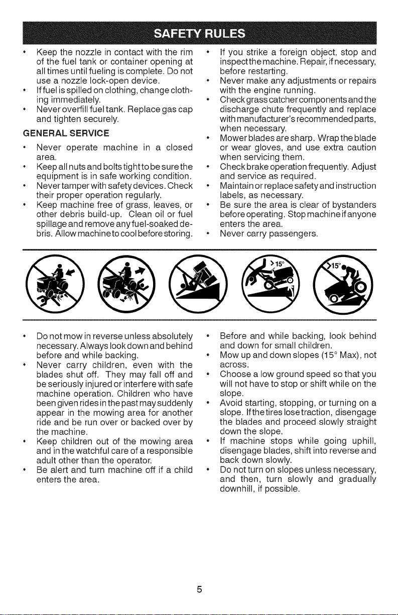
Mowupanddownslopes(15°Max),not
across.
Choosealowgroundspeedsothatyou
willnothavetostoporshiftwhileonthe
slope.
Avoidstarting,stopping,orturningona
slope.Ifthetirestosetraction,disengage
thebladesandproceedslowlystraight
downtheslope.
If machinestopswhilegoinguphill,
disengageblades,shiftintoreverseand
backdownslowly.
Donotturnonslopesunlessnecessary,
andthen,turnslowlyandgradually
downhill,ifpossible.
Page 6

PRODUCT SPECIFiCATiONS
Gasoline Capacity 1.5 Gallons
andType: Unleaded Regular
Oil Type SAE 30 (above 32°F)
API-SG-SL): SAE 5W30 (below32°F
Oil Capacity: W/Filter: 56 oz.
W/O Filter: 48 oz.
Spark Plug: Champion RC12YC
(Gap: .030")
Ground Speed Forward: 1st 1.0
2nd 1.4
3rd 2.1
4th 3.1
5th 4.0
6th 5.1
Reverse: 1.6
Charging System: 3 Amps Battery
5 Amps Headlights
Battery: Amp/Hr: 28
Min. CCA: 230
Case size: U1R
Blade Bolt Torque: 45-55 Ft. Lbs.
CONGRATULATIONS on your purchase of
a new tractor. It has been designed, engi-
neered and manufactured to give you the best
possible dependability and performance.
Should you experience any problem you
cannot easily remedy, please contact aSears
or other qualified service center. We have
competent, well-trained representatives
and the proper tools to service or repair
this tractor.
Please read and retain this manual. The
instructions will enable you to assemble
and maintain your tractor properly. Always
observe the "SAFETY RULES".
CUSTOMER RESPONSIBILITIES
Read and observe the safety rules.
* Follow a regular schedule in maintaining,
caring for and using your tractor.
Follow the instructions under "Mainte-
nance" and "Storage" sections of this
owner's manual.
_WARNING: This tractor is equipped with
an internal combustion engine and should not
be used on or near any unimproved forest-
covered, brush-covered or grass-covered
land unless the engine's exhaust system is
equipped with a spark arrester meeting ap-
plicable local or state laws (if any). If a spark
arrester is used, it should be maintained in
effective working order by the operator.
Inthe state of California the above is required
by law (Section 4442 of the California Public
Resources Code). Other states may have
similar laws. Federal laws apply on federal
lands. A spark arrester for the muffler is
available through your nearest Sears service
center (See REPAIR PARTS manual).
REPAIR PROTECTION
AGREEMENTS
Congratulations on making a smart purchase.
Your new Craftsman@ product is designed
and manufactured for years of dependable
operation. But like all products, it may require
repair from time to time. That's when having
a Repair Protection Agreement can save you
money and aggravation.
Purchase a Repair Protection Agreement
now and protect yourself from unexpected
hassle and expense.
Here's what's included in the Agreement:
* Expert service by our 12,000 profesional
repair specialists.
* Unlimited service and no charge for parts
and labor on all covered repairs.
* Product replacement if your covered
product can't be fixed.
* Discount of 10% from regular price of
service and service-related parts not
covered bythe agreement; also, 10% off
regular price of preventive maintenance
check.
* Fast help by phone - phone support
from a Sears representative on products
requiring in-home repair, plus convenient
repair scheduling.
Once you purchase the Agreement, a
simple phone call is all that it takes for you
to schedule service. You can call anytime
day or night, or schedule a service appoint-
ment online.
Sears has over 12,000 professional repair
specialists, who have access to over 4.5
million quality parts and accessories. That's
the kind of professionalism you can count on
to help prolong the life of your new purchase
for years to come. Purchase your Repair
Protection Agreement today!
Some limitations and exclusions apply.
For prices and additional information call
1-800=827-6655,
SEARS INSTALLATION SERVICE
For Sears professional installation of home
appliances, garage door openers, water
heaters, and other major home items, in the
U.S.A. call 1-800=4-MY-HOME@
6
Page 7
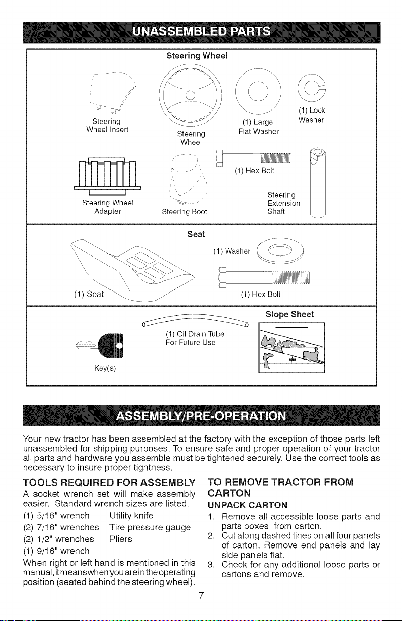
Steering Wheel
/ \
J
i
Steering
Wheel insert
I I _ , '%z j Steering
Steering Wheel "_<- .... Extension
Adapter Steering Boot Shaft
Steering
Wheel
//
- /
Seat
(1) Large
Fiat Washer
(1) Hex Bolt
(1) Washer
(1) Lock
Washer
(1) Seat _ .......... jJ (1) Hex Bolt
\
Slope Sheet
ForFutureUse
Key(s)
Your new tractor has been assembled at the factory with the exception of those parts left
unassembled for shipping purposes. To ensure safe and proper operation of your tractor
all parts and hardware you assemble must be tightened securely. Use the correct tools as
necessary to insure proper tightness.
TOOLS REQUIRED FOR ASSEMBLY
A socket wrench set will make assembly
easier. Standard wrench sizes are listed.
(1) 5/16" wrench Utility knife
(2) 7/16" wrenches Tire pressure gauge
(2) 1/2" wrenches Pliers
(1) 9/16" wrench
When right or left hand is mentioned in this
manual, itmeanswhen youarein theoperating
TO REMOVE TRACTOR FROM
CARTON
UNPACK CARTON
1. Remove all accessible loose parts and
parts boxes from carton.
2. Cut along dashed lines on allfour panels
of carton. Remove end panels and lay
side panels flat.
3. Check for any additional loose parts or
cartons and remove.
position (seated behind the steering wheel).
Page 8
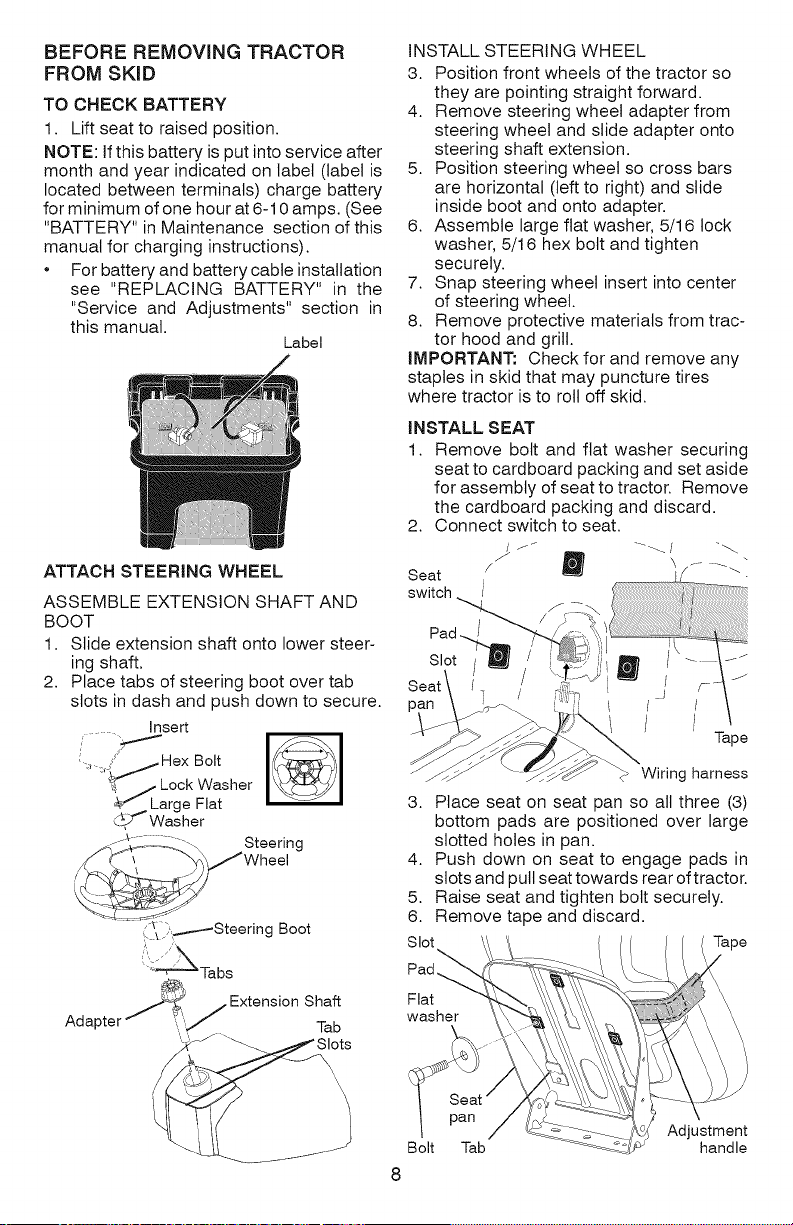
BEFORE REMOVING TRACTOR
FROM SKID
TO CHECK BATTERY
1. Lift seat to raised position.
NOTE: Ifthis battery is put into service after
month and year indicated on label (label is
located between terminals) charge battery
for minimum of one hour at 6-10 amps. (See
"BATTERY" in Maintenance section of this
manual for charging instructions).
• For batteryand batterycabte installation
see "REPLACING BATTERY" in the
"Service and Adjustments" section in
this manual.
Label
INSTALL STEERING WHEEL
3. Position front wheels of the tractor so
they are pointing straight forward.
4. Remove steering wheel adapter from
steering wheel and slide adapter onto
steering shaft extension.
5. Position steering wheel so cross bars
are horizontal (left to right) and slide
inside boot and onto adapter.
6. Assemble large flat washer, 5/16 lock
washer, 5/16 hex bolt and tighten
securely.
7. Snap steering wheel insert into center
of steering wheel.
8. Remove protective materials from trac-
tor hood and grill.
IMPORTANT: Check for and remove any
staples in skid that may puncture tires
where tractor is to roll off skid.
INSTALL SEAT
1. Remove bolt and flat washer securing
seat to cardboard packing and set aside
for assembly of seat to tractor. Remove
the cardboard packing and discard.
2. Connect switch to seat.
ATTACH STEERING WHEEL
ASSEMBLE EXTENSION SHAFT AND
BOOT
1. Slide extension shaft onto lower steer-
ing shaft.
2. Place tabs of steering boot over tab
slots in dash and push down to secure.
Insert
, :'jHexBolt
_I_'L L°gekFWla_sher
__,J'_Washer
/__/_,,, Steering
Wheel
__;i:'iSteering Boot
'::_Tabs
@:
ST? .ExtensionShah
Adapter f _'"/ Tab
,,_ --_
\
Seat / _ _ f- _""
switch
Slot
/
pan I i
3. Place seat on seat pan so all three (3)
bottom pads are positioned over large
slotted holes in pan.
4. Push down on seat to engage pads in
slots and pull seat towards rear of tractor.
5. Raise seat and tighten bolt securely.
6. Remove tape and discard.
Slot Tape
Flat
washer
pan
Bolt Tab handle
J
Wiring harness
Adjustment
8
Tape
Page 9
7. Lowerseatintooperatingpositionand
sitonseat.Pressclutch/brakepedalall
thewaydown.Ifoperatingpositionisnot
comfortable,adjustseat.
TO ADJUST SEAT
Grasp adjustment handle and pull up, slide
seat to desired position and release adjust-
ment handle.
NOTE: You may now roll your tractor off
the skid. Follow the appropriate instruction
below to remove the tractor from the skid.
WARNING: Before starting, read, un-
derstand and follow all instructions in the
Operation section of this manual. Be sure
tractor is in a welt-ventilated area. Be sure
the area in front of tractor is clear of other
people and objects.
TO ROLL TRACTOR OFF SKID
(See Operation section for location
and function of controls)
1. Raise attachment lift lever to its highest
position.
2. Release parking brake by depressing
clutch/brake pedal.
3. Place gearshift lever in neutral posi-
tion.
4. Roll tractor forward off skid.
5. Remove banding holding the deflector
shield up against tractor.
Continue with the instructions that follow.
CHECK TIRE PRESSURE
The tires onyour tractor were overinftated at
the factory for shipping purposes. Correct
tire pressure is important for best cutting
performance.
Reduce tire pressure to PSI shown on
tires.
CHECK DECK LEVELNESS
For best cutting results, mower housing
should be properly leveled. See "TO LEVEL
MOWER" in the Service and Adjustments
section of this manual.
CHECK FOR PROPER POSITION OF
ALL BELTS
See the figures that are shown for replacing
motion and mower blade drive belts in the
Service and Adjustments section ofthis man-
ual. Verify that the belts are routed correctly.
CHECK BRAKE SYSTEM
After you learn how to operate your tractor,
check to see that the brake is operating
properly. See "TO CHECK BRAKE" in the
Service and Adjustments section of this
manual.
Vf CHECKLIST
Before you operate your new tractor, we
wish to assure that you receive the best
performance and satisfaction from this
Quality Product.
Please review the following checklist:
vf All assembly instructions have been
completed.
vf No remaining loose parts in carton.
vfBattery is properly prepared and
charged.
vf Seat is adjusted comfortably and tight-
ened securely.
vf All tires are properly inflated. (For ship-
ping purposes, the tires were overinftated
at the factory).
vf Be sure mower deck is properly leveled
side-to-side/front-to-rear for best cutting
results. (Tires must be properly inflated
for leveling).
vf Check mower and drive belts. Be sure
they are routed properly around pulleys
and inside all belt keepers.
vf Check wiring. See that all connections
are still secure and wires are properly
clamped.
While learning howto use your tractor, pay ex-
tra attention to the following important items:
_/Engine oil is at proper level.
_/Fuel tank isfilled with fresh, clean, regular
unleaded gasoline.
_/Become familiar with all controls, their
location and function. Operate them
before you start the engine.
_/Be sure brake system is in safe operating
condition.
_/Be sure Operator Presence System and
Reverse Operation System (ROS) are
working properly (See the Operation and
Maintenance sections in this manual).
Page 10
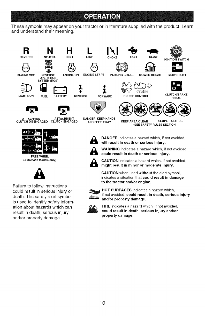
Thesesymbolsmayappearonyourtractororinliteraturesuppliedwiththeproduct.Learn
andunderstandtheirmeaning.
R N H L Ikl
REVERSE NEUTRAL HIGH LOW CHOKE FAST SLOW
IGNITION SWITCH
ENGINE OFF REVERSE ENGINE ON ENGINE START PARKING BRAKE MOWER HEIGHT
LIGHTS ON FUEL BATTERY REVERSE FORWARD PEDAL
ATTACHMENT ATTACHMENT
CLUTCH DISENGAGED CLUTCH ENGAGED
(Automatic Models only)
Failure to follow instructions
could result in serious injury or
death. The safety alert symbol
is used to identify safety inform-
ation about hazards which can
result in death, serious injury
and/or property damage.
m
FREE WHEEL
OPERATION
SYSTEM(ROS)
DANGER, KEEP HANDS
AND FEET AWAY
DANGER indicates a hazard which, if not avoided,
will result in death or serious injury.
WARNING indicates a hazard which, if net avoided,
could result in death or serious injury.
CAUTION indicates a hazard which, if not avoided,
might result in minor or moderate injury.
CAUTION when used without the alert symbol,
indicates a situation that could result in damage
to the tractor and/or engine.
HOT SURFACES indicates a hazard which,
if not avoided, could result in death, serious injury
.hlllI/l/JIb_,
and/or property damage.
FIRE indicates a hazard which, if not avoided,
could result in death, serious injury and/or
property damage.
CRUISE CONTROL
®@@@@
KEEP AREA CLEAR SLOPE HAZARDS
(SEE SAFETY RULES SECTION)
MOWER LIFT
CLUTCH/BRAKE
10
Page 11
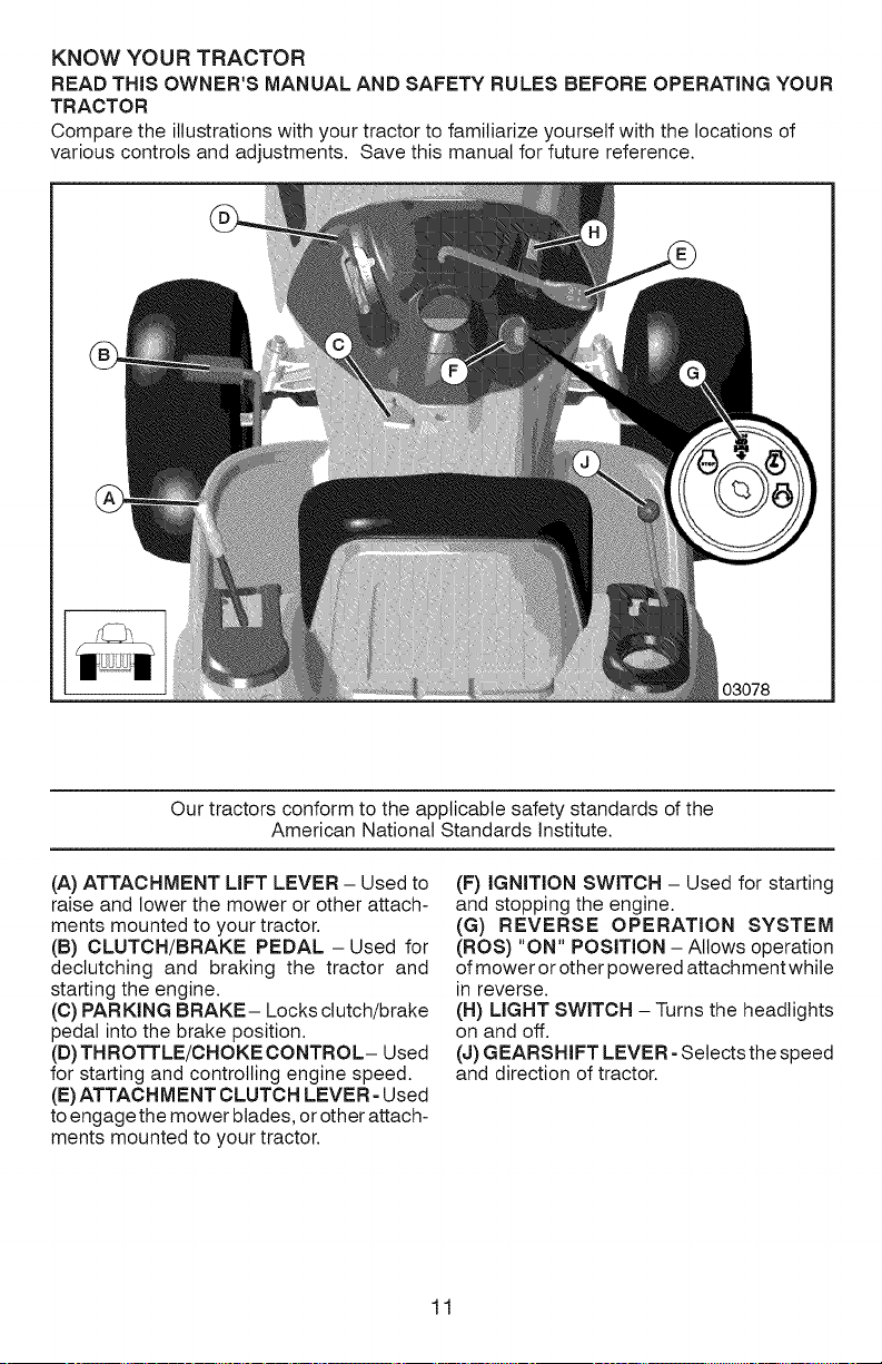
KNOW YOUR TRACTOR
READ THiS OWNER'S MANUAL AND SAFETY RULES BEFORE OPERATING YOUR
TRACTOR
Compare the illustrations with your tractor to familiarize yourself with the locations of
various controls and adjustments. Save this manual for future reference.
03078
Our tractors conform to the applicable safety standards of the
American National Standards Institute.
(A) ATTACHMENT LIFT LEVER - Used to
raise and lower the mower or other attach-
ments mounted to your tractor.
(B) CLUTCH/BRAKE PEDAL- Used for
dectutching and braking the tractor and
starting the engine.
(C) PAR KIN G BRAKE- Locks clutch/brake
pedal into the brake position.
(D) THROTTLE/CHOKE CONTROL- Used
for starting and controlling engine speed.
(E)ATTACHMENT CLUTCH LEVER- Used
to engage the mower blades, or other attach-
ments mounted to your tractor.
(F) IGNITION SWITCH - Used for starting
and stopping the engine.
(G) REVERSE OPERATION SYSTEM
(ROS) "ON" POSITION - Allows operation
of mower or other powered attachment while
in reverse.
(H) LIGHT SWITCH - Turns the headlights
on and off.
(J) GEARSHIFT LEVER - Selects the speed
and direction of tractor.
11
Page 12
The operation of any tractor can result in foreign objects thrown into
the eyes, which can result in severe eye damage. Always wear safety
glasses or eye shields while operating your tractor or performing any
adjustments or repairs. We recommend standard safety glasses or a
wide vision safety mask worn over spectacles.
HOW TO USE YOUR TRACTOR
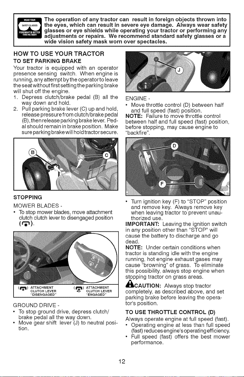
TO SET PARKING BRAKE
Your tractor is equipped with an operator
presence sensing switch. When engine is
running, any attempt by the operator to leave
the seat without first setting the parking brake
will shut off the engine.
1. Depress clutch/brake pedal (B) all the
way down and hold.
2. Putt parking brake lever (C) up and hold,
release pressure from clutch/brake pedal
(B),then release parking brake lever. Ped-
al should remain in brake position. Make
sure parking brake will holdtractor secure.
ENGINE -
• Move throttle control (D) between half
and full speed (fast) position.
NOTE: Failure to move throttle control
between half and futl speed (fast) position,
before stopping, may cause engine to
"backfire".
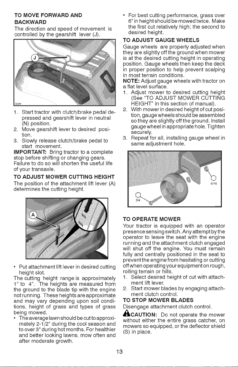
STOPPING
MOWER BLADES -
Tostop mower blades, move attachment
clutch clutch lever to disengaged position
(r_).
(1_) ATTACHMENT (ll_) ATTACHMENT
CLUTCH LEVER CLUTCH LEVER
"DISENGAGED .... ENGAGED"
GROUND DRIVE -
To stop ground drive, depress clutch/
brake pedal all the way down.
Move gear shift lever (J) to neutral posi-
tion.
Turn ignition key (F) to "STOP" position
and remove key. Always remove key
when leaving tractor to prevent unau-
thorized use.
IMPORTANT: Leaving the ignition switch
in any position other than "STOP" will
cause the battery to discharge and go
dead.
NOTE: Under certain conditions when
tractor is standing idte with the engine
running, hot engine exhaust gases may
cause "browning" of grass. To eliminate
this possibility, always stop engine when
stopping tractor on grass areas.
_i_,CAUTION: Always stop tractor
completely, as described above, and set
parking brake before leaving the opera-
tor's position.
TO USE THROTTLE CONTROL (D)
Always operate engine at full speed (fast).
* Operating engine at less than full speed
(fast) reduces engine's operating efficiency.
* Full speed (fast) offers the best mower
performance.
12
Page 13
TO MOVE FORWARD AND
BA CKWA RD
The direction and speed of movement
controlled by the gearshift lever (J).
1. Start tractor with clutch/brake pedal de-
pressed and gearshift lever in neutral
(N) position.
2. Move gearshift lever to desired posi-
tion.
3. Slowly release clutch/brake pedal to
start movement.
IMPORTANT: Bring tractor to a complete
stop before shifting or changing gears.
Failure to do so will shorten the useful life
of your transaxle.
TO ADJUST MOWER CUTTING HEIGHT
The position of the attachment lift lever (A)
determines the cutting height.
For best cutting performance, grass over
6" in heightshoutd be mowed twice. Make
the first cut relatively high; the second to
desired height.
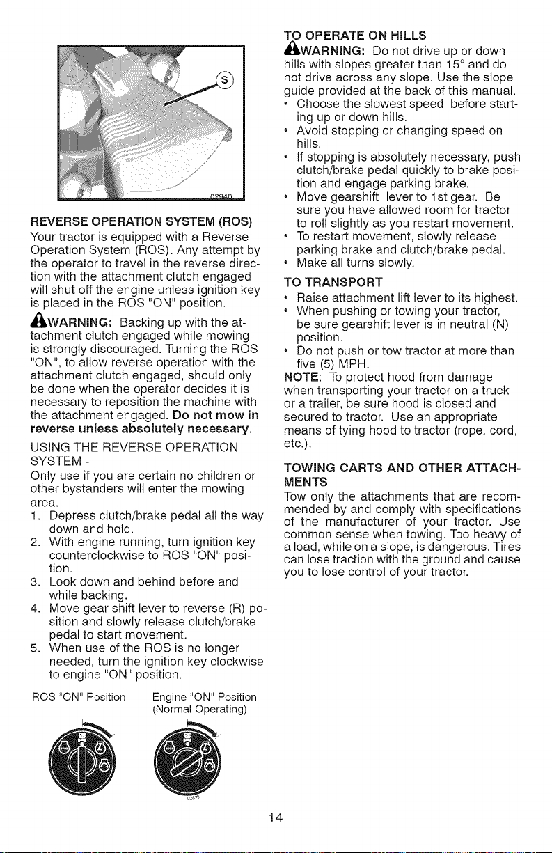
TO ADJUST GAUGE WHEELS
Gauge wheels are properly adjusted when
they are slightly off the ground when mower
is at the desired cutting height in operating
position. Gauge wheels then keep the deck
in proper position to help prevent scalping
in most terrain conditions.
NOTE: Adjust gauge wheels with tractor on
a flat level surface.
1. Adjust mower to desired cutting height
(See "TO ADJUST MOWER CUTTING
HEIGHT" in this section of manual).
2. With mower in desired height of cut posi-
tion, gauge wheels should be assembled
so they are slightly off the ground. Install
gauge wheel in appropriate hole. Tighten
securely.
3. Repeat for all, installing gauge wheel in
same adjustment hole.
Put attachment lift lever in desired cutting
height slot.
The cutting height range is approximately
1" to 4". The heights are measured from
the ground to the blade tip with the engine
not running. These heights are approximate
and may vary depending upon soil condi-
tions, height of grass and types of grass
being mowed.
The average lawn should be cutto approxi-
mately 2-1/2" during the coot season and
to over 3" during hot months. For healthier
and better looking lawns, mow often and
after moderate growth.
TO OPERATE MOWER
Your tractor is equipped with an operator
presence sensing switch. Any attempt bythe
operator to leave the seat with the engine
running and the attachment clutch engaged
will shut off the engine. You must remain
fully and centrally positioned in the seat to
preventthe engine from hesitating or cutting
offwhen operating your equipmenton rough,
rolling terrain or hills.
1. Select desired height of cut with attach-
ment lift lever.
2. Start mower blades by engaging attach-
ment clutch control.
TO STOP MOWER BLADES
Disengage attachment clutch control.
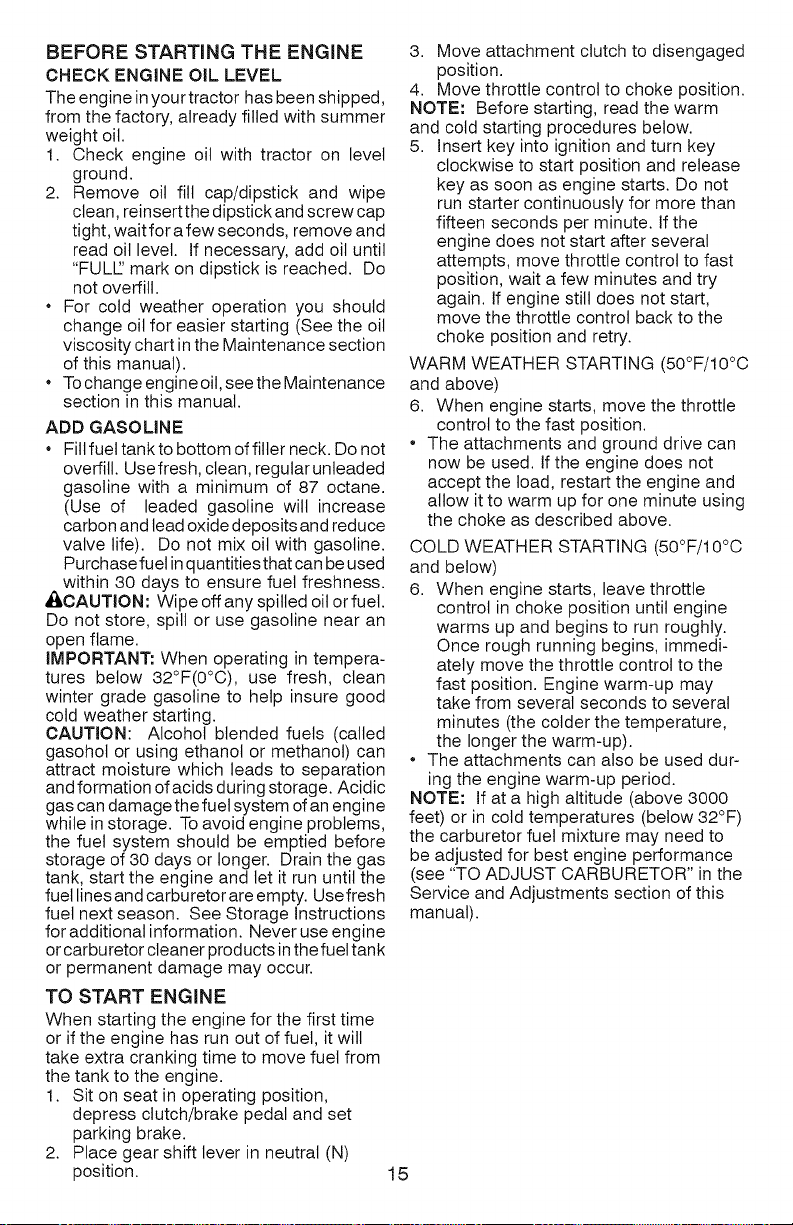
Ai_CAUTION: Do not operate the mower
without either the entire grass catcher, on
mowers so equipped, or the deflector shield
(S) in place.
13
Page 14
REVERSE OPERATION SYSTEM (ROS)
Your tractor is equipped with a Reverse
Operation System (ROS). Any attempt by
the operator to travel in the reverse direc-
tion with the attachment clutch engaged
wilt shut off the engine unless ignition key
is placed in the ROS "ON" position.
_,WARNING: Backing up with the at-
tachment clutch engaged while mowing
is strongly discouraged. Turning the ROS
"ON", to allow reverse operation with the
attachment clutch engaged, should only
be done when the operator decides it is
necessary to reposition the machine with
the attachment engaged. Do not mow in
reverse unless absolutely necessary.
USING THE REVERSE OPERATION
SYSTEM -
Only use if you are certain no children or
other bystanders will enter the mowing
area.
1. Depress clutch/brake pedal all the way
down and hold.
2. With engine running, turn ignition key
counterclockwise to ROS "ON" posi-
tion.
3. Look down and behind before and
while backing.
4. Move gear shift lever to reverse (R) po-
sition and slowly release clutch/brake
pedal to start movement.
5. When use of the ROS is no longer
needed, turn the ignition key clockwise
to engine "ON" position.
ROS "ON" Position Engine "ON" Position
(Normal Operating)
TO OPERATE ON HILLS
_;_WARNING: Do not drive up or down
hills with slopes greater than 15° and do
not drive across any slope. Use the slope
guide provided at the back of this manual.
• Choose the slowest speed before start-
ing up or down hills.
• Avoid stopping or changing speed on
hills.
• If stopping is absolutely necessary, push
clutch/brake pedal quickly to brake posi-
tion and engage parking brake.
• Move gearshift lever to 1st gear. Be
sure you have allowed room for tractor
to roll slightly as you restart movement.
• To restart movement, slowly release
parking brake and clutch/brake pedal.
• Make all turns slowly.
TO TRANSPORT
• Raise attachment lift lever to its highest.
• When pushing or towing your tractor,
be sure gearshift lever is in neutral (N)
position.
• Do not push or tow tractor at more than
five (5) MPH.
NOTE: To protect hood from damage
when transporting your tractor on a truck
or a trailer, be sure hood is closed and
secured to tractor. Use an appropriate
means of tying hood to tractor (rope, cord,
etc.).
TOWING CARTS AND OTHER ATTACH-
MENTS
Tow only the attachments that are recom-
mended by and comply with specifications
of the manufacturer of your tractor. Use
common sense when towing. Too heavy of
a load, while on a slope, is dangerous. Tires
can lose traction with the ground and cause
you to lose control of your tractor.
14
Page 15
BEFORESTARTINGTHE ENGINE
CHECK ENGINE OIL LEVEL
The engine inyour tractor has been shipped,
from the factory, already filled with summer
weight oil.
1. Check engine oil with tractor on level
ground.
2. Remove oil fill cap/dipstick and wipe
clean, reinsertthe dipstick and screw cap
tight, wait for a few seconds, remove and
read oil level. If necessary, add oil until
"FUL[L' mark on dipstick is reached. Do
not overfill.
For cold weather operation you should
change oil for easier starting (See the oil
viscosity chart inthe Maintenance section
of this manual).
Tochange engine oil, see the Maintenance
section in this manual.
ADD GASOLINE
* Fill fuel tank to bottom of filler neck. Do not
overfill. Usefresh, clean, regutar unleaded
gasoline with a minimum of 87 octane.
(Use of leaded gasoline will increase
carbon and leadoxide deposits and reduce
valve life). Do not mix oil with gasoline.
Purchase fuel in quantities that can be used
within 30 days to ensure fuel freshness.
_kCAUTION: Wipe off any spilled oil orfuel.
Do not store, spill or use gasoline near an
open flame.
IMPORTANT: When operating in tempera-
tures below 32°F(0°C), use fresh, clean
winter grade gasoline to help insure good
cold weather starting.
CAUTION: Alcohol blended fuels (called
gasohol or using ethanol or methanol) can
attract moisture which leads to separation
and formation of acids during storage. Acidic
gas can damage the fuel system ofan engine
while in storage. To avoid engine problems,
the fuel system should be emptied before
storage of 30 days or longer. Drain the gas
tank, start the engine and let it run until the
fuel linesand carburetorare empty. Usefresh
fuel next season. See Storage Instructions
for additional information. Never use engine
orcarburetor cleaner products in the fuel tank
or permanent damage may occur.
TO START ENGINE
When starting the engine for the first time
or if the engine has run out of fuel, it will
take extra cranking time to move fuel from
the tank to the engine.
1. Sit on seat in operating position,
depress clutch/brake pedal and set
parking brake.
2. Place gear shift lever in neutral (N)
position. 15
3. Move attachment clutch to disengaged
position.
4. Move throttle control to choke position.
NOTE: Before starting, read the warm
and cold starting procedures below.
5. Insert key into ignition and turn key
clockwise to start position and release
key as soon as engine starts. Do not
run starter continuously for more than
fifteen seconds per minute. If the
engine does not start after several
attempts, move throttle control to fast
position, wait a few minutes and try
again. If engine still does not start,
move the throttle control back to the
choke position and retry.
WARM WEATHER STARTING (50°F/10°C
and above)
6. When engine starts, move the throttle
control to the fast position.
* The attachments and ground drive can
now be used. Ifthe engine does not
accept the toad, restart the engine and
allow it to warm up for one minute using
the choke as described above.
COLD WEATHER STARTING (50°F/10°C
and below)
6. When engine starts, leave throttle
control in choke position until engine
warms up and begins to run roughly.
Once rough running begins, immedi-
ately move the throttle control to the
fast position. Engine warm-up may
take from several seconds to several
minutes (the colder the temperature,
the longer the warm-up).
* The attachments can also be used dur-
ing the engine warm-up period.
NOTE: If at a high altitude (above 3000
feet) or in cold temperatures (below 32°F)
the carburetor fuel mixture may need to
be adjusted for best engine performance
(see "TO ADJUST CARBURETOR" in the
Service and Adjustments section of this
manual).
Page 16
MOWING TiPS
• Tire chains cannot be used when the
mower housing is attached to tractor.
• Mower should be properly leveled for best
mowing performance. See "TO LEVEL
MOWER HOUSING" in the Service and
Adjustments section of this manual.
• The left hand side of mower should be
used for trimming.
• Drive so that clippings are discharged onto
the area that has already been cut. Have
the cut area to the right ofthe tractor. This
will result in a more even distribution of
clippings and more uniform cutting.
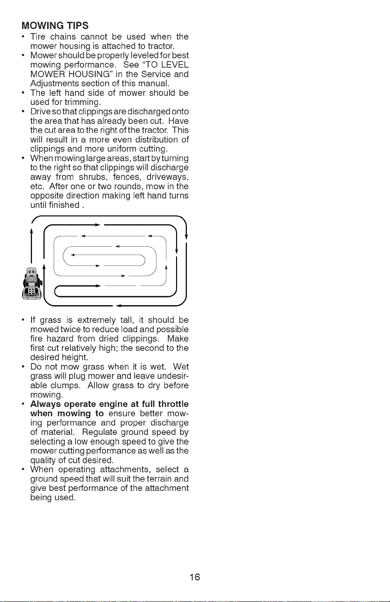
• When mowing large areas, start byturning
to the right so that clippings will discharge
away from shrubs, fences, driveways,
etc. After one or two rounds, mow in the
opposite direction making left hand turns
until finished.
f
:1
f
, " JJ
, )
• If grass is extremely tall, it should be
mowed twice to reduce load and possible
fire hazard from dried clippings. Make
first cut relatively high; the second to the
desired height.
• Do not mow grass when it is wet. Wet
grass will plug mower and leave undesir-
able clumps. Allow grass to dry before
mowing.
• Always operate engine at full throttle
when mowing to ensure better mow-
ing performance and proper discharge
of material. Regulate ground speed by
selecting a low enough speed to give the
mower cutting performance as well as the
quality of cut desired.
• When operating attachments, select a
ground speed that will suit the terrain and
give best performance of the attachment
being used.
16
Page 17
MAINTENANCE BEFOREEACH EVERY8 EVERY25 EVERY
SCHEDULE USE SOURS.OURS SOURS
Check Brake Operation _
Check Tire Pressure
Check Operator Presence & ROS Systems
A Check for Loose Fasteners
C Check/Replace Mower Blades _3
] Lubrication Chart
0 Check Battery Level ,_4
R Clean Battery andTerminals
Clean Debris Off Steering Plate
Check Transaxle Cooling
Check Mower Levelness
Check V-Belts
Check Enqine Oil Level _
Chanqe Enqine Oil (with oil filter) _##'1_2
Change Engine Oil (without oil filter) _1,2
Clean Air Filter _
G Clean Air Screen _2
Inspect Muffler/Spark Arrester
N Replace Oil Filter/If equipped)
E Clean Engine Cooling Fins
Replace Spark Plug
Replace Air Filter Paper Cartridge
-- Re lace Fuel Filter ______
Changemoreoftenw]_eflopefatingundefaheawloadorir_higtlamMel_ttem]aeratureG 3 Replaoebladesmoreoftenw]_enmowJngil_sandysoil 5 SeeClear_i_lginMaintenanoeSeotion
2 Serv_oreoft_w_,eno_e,at_ngJ_d_,tyo, du_tycond_t_on8 4 Notrequ_red_equ_p_dw_t_ma_n_enan_re_b_tt_ry
EVERY EVERY BEFORE
100 SEASON STORAGE
HOURS
1#'_,2
m_m
v'
t,z
GENERAL RECOMMENDATIONS
The warranty on this tractor does not
cover items that have been subjected to
operator abuse or negligence. To receive
full value from the warranty, operator
must maintain tractor as instructed in this
manual.
Some adjustments will need to be made
periodically to properly maintain your
tractor.
At least once a season, check to see if
you should make any of the adjustments
described in the Service and Adjustments
section of this manual.
• At least once a year you should replace
the spark plug, clean or replace air filter,
and check blades and belts for wear.
A new spark plug and clean air filter
assure proper air-fuel mixture and help
your engine run better and last longer.
BEFORE EACH USE
1. Check engine oil level.
2. Check brake operation.
3. Check tire pressure.
4. Check operator presence and
ROS systems for proper operation.
5. Check for loose fasteners.
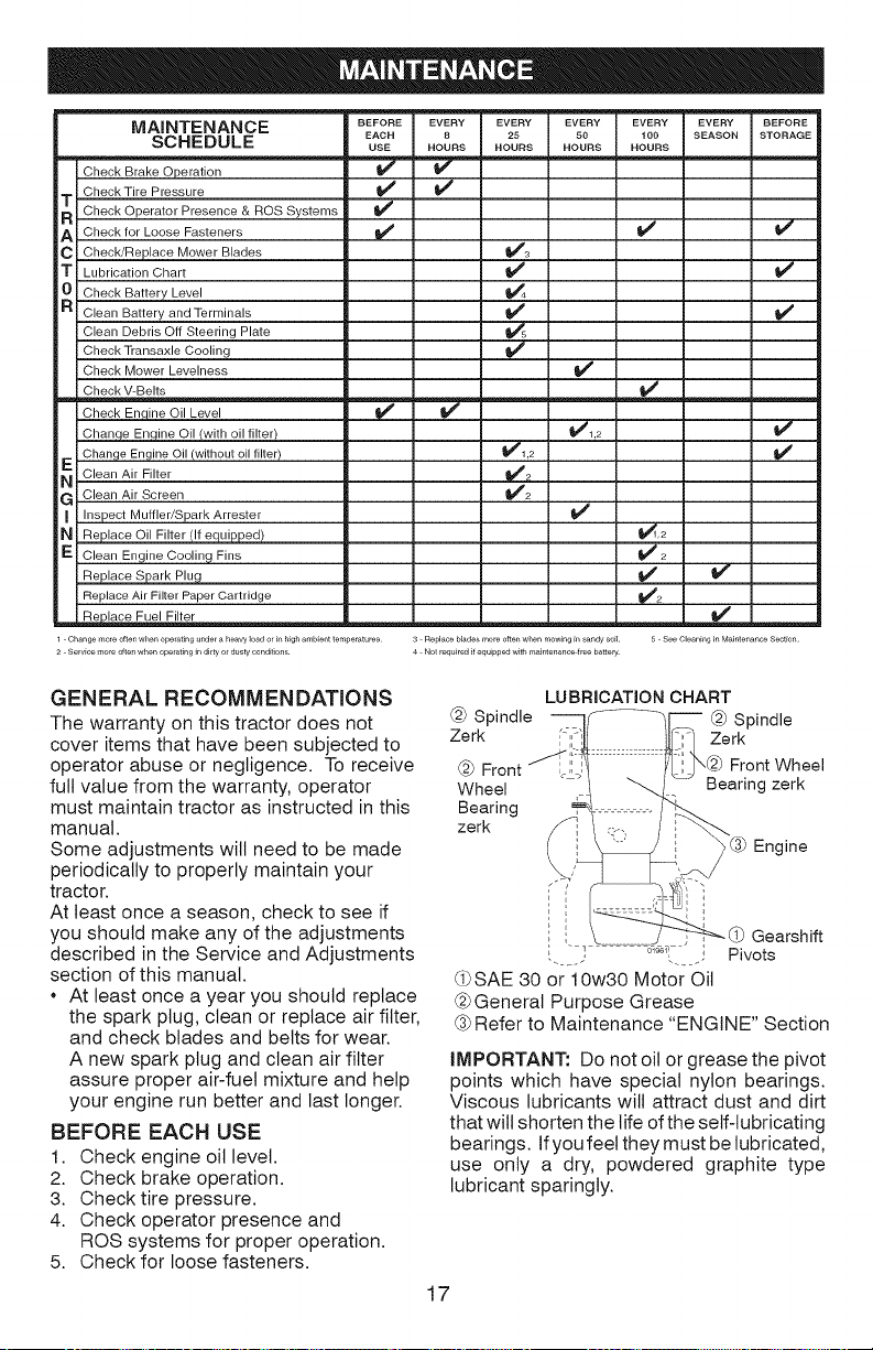
LUBRICATION CHART
@ Spindle @ Spindle
Zerk Zerk
@ ,@ Front Wheel
Wheel Bearing zerk
Bearing
zerk
Engine
Gearshift
" 019611 ; Pivots
(_SAE 30 or 10w30 Motor Oil
@General Purpose Grease
(-3;Refer to Maintenance "ENGINE" Section
iMPORTANT: Do not oil or grease the pivot
points which have special nylon bearings.
Viscous lubricants wilt attract dust and dirt
that will shorten the life ofthe self-lubricating
bearings. Ifyou feel they must be lubricated,
use only a dry, powdered graphite type
lubricant sparingly.
17
Page 18
TRACTOR
Alwaysobservesafetyruleswhenperforming
anymaintenance.
BRAKEOPERATION
Iftractorrequiresmorethanfive(5)feetto
stopathighestspeedinhighestgearona
level,dryconcreteorpavedsurface,then
brakemustbeserviced.(See"TOCHECK
BRAKE"intheServiceandAdjustments
sectionofthismanual).
TIRES
• Maintain proper air pressure in all tires
(See the sides of tires for proper PSI).
Keep tires free of gasoline, oil, or insect
control chemicals which can harm rubber.
Avoid stumps, stones, deep ruts, sharp
objects and other hazards that may cause
tire damage.
NOTE: To seal tire punctures and prevent
flat tires due to slow leaks, tire sealant may
be purchased from your local parts dealer.
Tire sealant also prevents tire dry rot and
corrosion.
OPERATOR PRESENCE SYSTEM AND
REVERSE OPERATION SYSTEM (ROS)
Be sure operator presence and reverse
operation systems are working properly. If
your tractor does not function as described,
repair the problem immediately.
The engine should not start unless the
brake pedal is fully depressed, and the
attachment clutch control is inthe disen-
gaged position.
CHECK OPERATOR PRESENCE
SYSTEM
When the engine is running, any attempt
by the operator to leave the seat without
first setting the parking brake should shut
off the engine.
When the engine is running and the at-
tachment clutch is engaged, any attempt
by the operator to leave the seat should
shut off the engine.
The attachment clutch should never oper-
ate unless the operator is in the seat.
CHECK REVERSE OPERATION (ROS)
SYSTEM
When the engine isrunning with the ignition
switch in the engine "ON" position and the
attachment clutch engaged, any attempt
by the operator to drive in reverse should
shut off the engine.
When the engine isrunning with the ignition
switch in the ROS "ON" position and the
attachment clutch engaged, any attempt
by the operator to drive in reverse should
NOT shut off the engine.
BLADE CARE
For best results mower blades must be sharp.
Replace worn, bent or damaged blades.
_, CAUTION" Use only a replacement
blade approved by the manufacturer of your
tractor. Using a blade not approved by the
manufacturer of your tractor is hazardous,
could damage your tractor and void your
warranty.
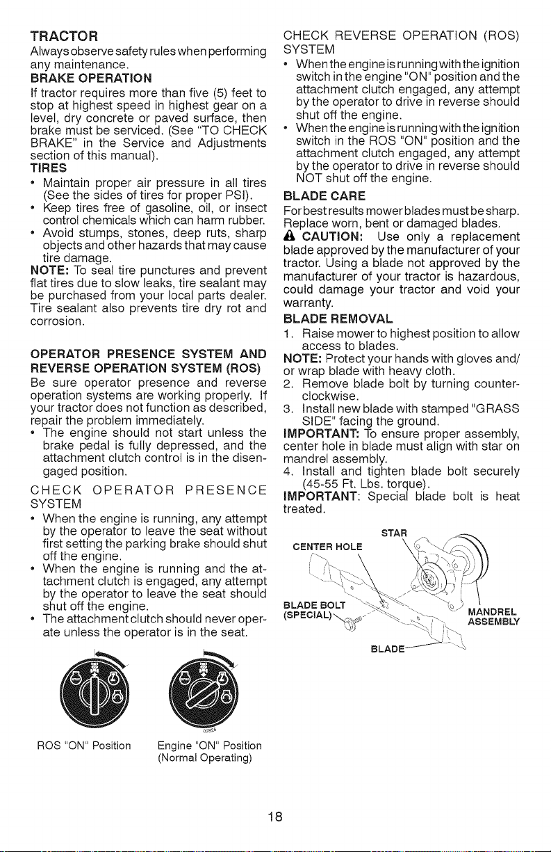
BLADE REMOVAL
1. Raise mower to highest position to allow
access to blades.
NOTE: Protect your hands with gloves and/
or wrap blade with heavy cloth.
2. Remove blade bolt by turning counter-
clockwise.
3. install new blade with stamped "GRASS
SIDE" facing the ground.
iMPORTANT: To ensure proper assembly,
center hole in blade must align with star on
mandrel assembly.
4. install and tighten blade bolt securely
(45-55 Ft. Lbs. torque).
iMPORTANT: Special blade bolt is heat
treated.
STAR
CENTER HOLE \
BLADE BOLT &J MANDREL
(SPECiAL)_ _j ASSEMBLY
ROS "ON" Position
Engine "ON" Position
(Normal Operating)
18
Page 19
BATTE RY
Your tractor has a battery charging system
which is sufficient for normal use. However,
periodic charging of the battery with an au-
tomotive charger will extend its life.
Keep battery and terminals clean.
Keep battery bolts tight.
Keep small vent holes open.
Recharge at 6-10 amperes for 1 hour.
NOTE: The original equipment battery on
your tractor is maintenance free. Do not
attempt to open or remove caps or covers.
Adding or checking level of electrolyte is
not necessary.
TO CLEAN BATTERY AND TERMINALS
Corrosion and dirt onthe battery and terminals
can cause the battery to "leak" power.
1. Disconnect BLACK battery cable first
then RED battery cable and remove
battery from tractor.
2. Rinse the battery with plain water and dry.
3. Clean terminals and battery cable ends
with wire brush until bright.
4. Coat terminals with grease or petroleum
jelly.
5. Reinstall battery (See "REPLACING
BATTERY" in the SERVICE AND AD-
JUSTMENTS section of this manual).
TRANSAXLE MAINTENANCE
Keep transaxle free from build-up of dirt and
chaff which can restrict cooling.
Do not attempt to clean transaxle while
engine is running or while the transaxle is
hot. To prevent possible damage to seals,
do not use high pressure water or steam to
clean transaxte.
V=BELTS
CheckV-belts for deterioration and wear after
100 hours of operation and replace if neces-
sary. The belts are not adjustable. Replace
belts if they begin to slip from wear.
ENGINE
LUBRiCATiON
Only use high quality detergent oil rated
with API service classification SG-SL.
Select the oil's SAE viscosity grade
according to your expected operating
temperature.
SAE VISCOSITY GRADES
NOTE: Although multi-viscosity oils (5W30,
10W30 etc.) improve starting in cold weather,
they will result in increased oil consumption
when used above 32°R Check your engine
oil level more frequently to avoid possible
engine damage from running low on oil.
Change the oil after every 50 hours of op-
eration or at least once a year if the tractor
is not used for 50 hours in one year.
Check the crankcase oil level before
starting the engine and after each eight
(8) hours of operation. Tighten oil fill cap/
dipstick securely each time you check the
oil level.
TO CHANGE ENGINE OiL
Determine temperature range expected
before oil change. All oil must meet API
service classification SG-SL.
Be sure tractor is on level surface.
Oil will drain more freely when warm.
Catch oil in a suitable container.
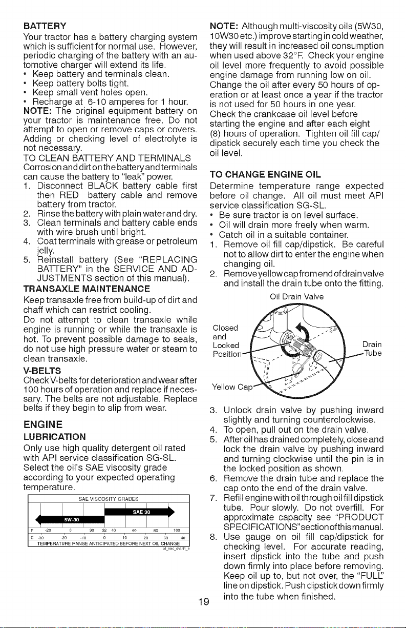
1. Remove oil fill cap/dipstick. Be careful
not to allow dirt to enter the engine when
changing oil.
2. Remove yetlow cap from endof drainvalve
and install the drain tube onto the fitting.
Oil DrainValve
CeaSed
Yellow Cap_
3. Unlock drain valve by pushing inward
slightly and turning counterclockwise.
4. To open, pull out on the drain valve.
5. After oilhas drained completely, close and
lock the drain valve by pushing inward
and turning clockwise until the pin is in
the locked position as shown.
6. Remove the drain tube and replace the
cap onto the end of the drain valve.
7. Refill engine with oil through oil fill dipstick
tube. Pour slowly. Do not overfill. For
approximate capacity see "PRODUCT
SPECIFICATIONS"section ofthismanual.
8. Use gauge on oil fill cap/dipstick for
checking level. For accurate reading,
insert dipstick into the tube and push
down firmly into place before removing.
Keep oil up to, but not over, the "FULL['
line on dipstick. Push dipstick down firmly
into the tube when finished.
19
._Tube
Page 20
ENGINE OIL FILTER
Replace the engine oil filter every season or
every other oil change if the tractor is used
more than 100 hours in one year.
AIR FILTER
Your engine will not run properly using
a dirty air filter. Service air cleaner more
often under dusty conditions. See Engine
Manual.
CLEAN AiR SCREEN
Air screen must be kept free of dirt and chaff
to prevent engine damage from overheating.
Clean with a wire brush or compressed air to
remove dirt and stubborn dried gum fibers.
ENGINE COOLING SYSTEM
Debris may clog the engine's air cooling
system. Remove blower housing and clean
area shown to prevent overheating and
engine damage.
Air Screen Clean out chaff
MUFFLER
inspect and replace corroded muffler and
spark arrester (ifequipped) as it could create
a fire hazard and/or damage.
SPARK PLUG(S)
Replace spark plug(s) atthe beginning ofeach
mowing season or after every 100 hours of
operation, whichever occurs first. Sparkptug
type and gap setting are shown in "PROD UCT
SPECIFICATIONS" section of this manual.
IN=LINE FUEL FILTER
The fuel filter should be replaced once each
season. If fuel filter becomes clogged, ob-
structing fuel flow to carburetor, replacement
is required.
1. With engine cool, remove filter and plug
fuel line sections.
2. Place new fuel filter inposition in fuel line
with arrow pointing towards carburetor.
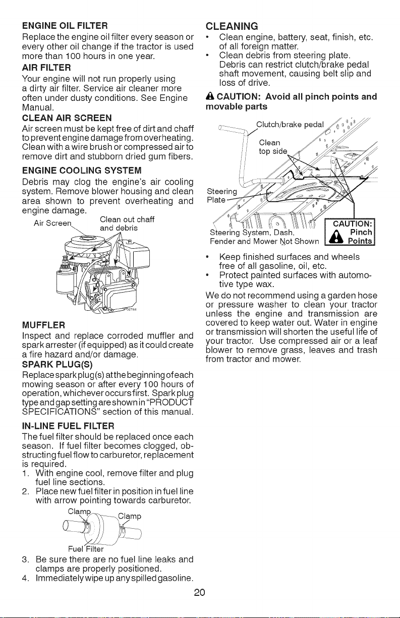
CLEANING
• Clean engine, battery, seat, finish, etc.
of alt foreign matter.
• Clean debris from steering plate.
Debris can restrict clutch/brake pedal
shaft movement, causing belt slip and
loss of drive.
_, CAUTION: Avoid all pinch points and
movable parts
Clutch/brake pedal
Clean
top side
Steering
Plate
CAUTION:
S;_eeringSystem, Dash, _ Pinch
Fenderand Mower Uot Shown _ Points
• Keep finished surfaces and wheels
free of all gasoline, oil, etc.
• Protect painted surfaces with automo-
tive type wax.
We do not recommend using a garden hose
or pressure washer to clean your tractor
unless the engine and transmission are
covered to keep water out. Water in engine
or transmission wilt shorten the useful life of
your tractor. Use compressed air or a leaf
blower to remove grass, leaves and trash
from tractor and mower.
Fuel "Filter
3. Be sure there are no fuel line leaks and
clamps are properly positioned.
4. Immediatetywipe up anyspilled gasoline.
20
Page 21

WARNING: TO AVOID SERIOUS iNJURY, BEFORE PERFORMING ANY
SERVICE OR ADJUSTMENTS:
1. Depress clutch/brake pedal fully and set parking brake.
2. Place gearshift lever in neutral (N) position.
3. Place attachment clutch in "DISENGAGED" position.
4. Turn ignition key to "STOP" and remove key.
5. Make sure the blades and all moving parts have completely stopped.
6. Disconnect spark plug wire from spark plug and place wire where it cannot
come in contact with plug.
TO REMOVE MOWER
1. Place attachment clutch in "DISEN-
GAGED" position.
2. Lower attachment lift lever to its lowest
position.
3. Roll belt off engine pulley (M) and belt
keepers (G).
4. Remove retainer spring (K), slide collar
(L) off and push housing guide (P) out
of bracket.
5. Remove clutch cable spring (Q) from
idler arm (R).
6. Disconnect front link (E) from mower -
remove retainer spring and washer.
7. Go to either side of mower and discon-
nect mower suspension arm (A) from
chassis pin (B) and rear lift link (C) from
rear mower bracket (D) - remove retainer
springs and washers.
_f_ CAUTION: After rear lift links are discon-
nected, the attachment lift lever will bespring
loaded. Have a tight grip on lift lever when
8. Slide mower out from under right side of
tractor.
IMPORTANT: If an attachment other than
the mower is to be mounted on the tractor,
remove the front link (E) and rear lift links
(C) from tractor and hook the clutch spring
(Q) into the cable guide on front edge of
lower dash.
TO iNSTALL MOWER
Be sure tractor ison level surface and engage
parking brake.
1. Lower attachment lift lever to its lowest
position.
CAUTION: Lift lever is spring loaded.
Have a tight grip on lift lever, lower it slowly
and engage in lowest position.
NOTE: Be sure mower side suspension
arms (A) are pointing forward before sliding
mower under tractor.
2. Slide mower under tractor until it is cen-
tered under tractor.
changing position of the lever.
21
03042tex
Page 22

3. ATTACH MOWER SIDE SUSPENSION
ARMS (A) TO CHASSIS - Position hole
in arm over pin (B) on outside of tractor
chassis and secure with retainer spring.
4. Repeat on opposite side of tractor.
7. Insert end of link (E) into hole in front
mower bracket (H) and secure with
washer and retainer spring (J).
5,
ATTACH REAR LIFT LINKS (C) - Lift
rear corner of mower and position slot
in link assembly over pin (D) on rear
mower bracket and secure with washer
and retainer spring.
6,
ATTACH FRONT LINK (E) - Work from
left side of tractor. Insert rod end of link
assembly through front hole in tractor
front suspension bracket (F).
%
8. Hook end of clutch cable spring (Q) into
hole in idler arm (R).
9. Push clutch cable housing guide (P) into
bracket, slide collar (L) onto guide and
secure with retainer spring (K).
10. Install belt onto engine pulley (M) and belt
keepers (G).
IMPORTANT: Check belt for proper routing
in all mower pulley grooves.
11.Raise attachment lift lever to highest
position.
12. If necessary, adjust gauge wheels before
operating mower as shown in the Opera-
tion section of this manual.
22
03042rex
Page 23

TO LEVEL MOWER
Make sure tires are properly inflated to the
PSI shown on tires. If tires are over or under
inflated, itmay affect the appearance of your
lawn and lead you to think the mower is not
adjusted properly.
VISUAL SIDE=TO-SIDE ADJUSTMENT
1. With all tires properly inflated and if your
lawn appears unevenly cut, determine
which side of mower is cutting lower.
2. With a 3/4" or adjustable wrench, turn lift
link adjustment nut (A) to the left to lower
LH side of mower, or,to the right to raise
LH side of mower.
NOTE: Each full turn of adjustment nut will
change mower height about 3/16".
FRONT-TO-BACK ADJUSTMENT
IMPORTANT: Deck must be level side-
to-side.
Toobtain the best cutting results, the mower
blades should be adjusted so the front tip is
1/8" to 1/2" lower than the rear tip when the
ower is in its highest position.
CAUTION: Blades are sharp. Protect
your hands with gloves and/or wrap blade
with heavy cloth.
• Raise mower to highest position.
Position any blade so the tip is pointing
straight forward. Measure distance (B)
to the ground at front and rear tip of the
blade.
Iffront tip of blade is not 1/8"to 1/2" lower
than the rear tip, go to the front of tractor.
• With an 11/16" or adjustable wrench,
loosen jam nut A several turns to clear
adjustment nut B.
Turn nut rig Turn nut left
to raise mower to lower mower
3. Test your adjustment by mowing some
uncut grass and visually checking the
appearance. Readjust, if necessary, until
you are satisfied with the results.
PRECISION SIDE=TO=SIDE ADJUSTMENT
1. With alttires properly inflated, parktractor
on level ground or driveway.
_iL CAUTION: Blades are sharp. Protect
your hands with gloves and/or wrap blade
with heavy cloth.
2. Raise mower to its highest position.
3. At both sides of mower, position blade at
side and measure the distance (A) from
bottom edge of blade to the ground. The
distance should be the same on both
sides.
4. If adjustment is necessary, see step 2 in
Visual Adjustment instructions above.
5. Recheckmeasurements, adjustifneces-
sary until both sides are equal.
AI L' hJ W IA
With a 3/4" or adjustable wrench, turn
front link adjustment nut (B) clockwise
(tighten) to raise the front of mower, or,
counterclockwise (loosen) to lower the
front mower.
Tighten adjust nut Loosen adjust
B to raise mower nut B to lower
Loosen jam nut A first
NOTE: Each full turn of the adjustment nut
will change mower height about 1/8".
• Recheck measurements, adjust if neces-
sary until front tip of blade is 1/8" to 1/2"
lower than the rear tip.
• Hold adjustment nut in position with wrench
and tighten jam nut securely against ad-
justment nut.
23
mower
Page 24

TO REPLACE MOWER BLADE DRIVE BELT
The mower blade drive belt may be replaced
without tools. Park the tractor on level sur-
face. Engage parking brake.
BELT REMOVAL -
1. Removemowerfromtractor (See"TO RE-
MOVE MOWER"inthissectionofmanual).
2. Work belt off both mandrel pulleys and
idler pulleys.
3. Putt belt away from mower.
BELT INSTALLATION -
1. Work belt around both mandrel pulleys
and idler pulleys
2. Make sure belt is in all pulley grooves
and inside all belt guides.
3. Install mower (See "To Install Mower" in
this section of this manual).
Mandrel Idler
Pulle_ Pulle,
Mandrel
BELT INSTALLATION -
1. Install new belt from tractor rear to
front, over the steering plate (F) and
above clutch brake pedal shaft (G).
2. Pull belt toward front of tractor and roll
belt onto engine pulley (E).
3. Pull belt toward rear of tractor. Care-
fully work belt down around transaxle
input pulley (D). Be sure belt is inside
the belt keeper.
4. Install belt through stationary idler (A)
and clutching idler (B).
5. Make sure belt is in all pulley grooves
and inside all belt guides and keepers.
6. Install mower (See "TO INSTALL
MOWER" in this section of manual).
TO REPLACE MOTION DRIVE BELT
Park the tractor on level surface. Engage
parking brake. For assistance, there is
a belt installation guide decal on bottom
side of left footrest.
BELT REMOVAL -
1. Remove mower (See "TO REMOVE
MOWER" in this section of manual).
NOTE: Observe entire motion drive belt
and position of all belt guides and keepers.
2. Remove belt from stationary idler (A)
and clutching idler (B).
3. Pull belt slack toward rear of tractor.
Remove belt upwards from transaxle
input pulley (D).
4. Remove belt downward from engine
pulley (E).
5. Slide belt toward rear of tractor, off the
steering plate (F)and remove from tractor.
TO CHECK BRAKE
If tractor requires more than five (5) feet to
stop at highest speed in highest gear on a
level, dry concrete or paved surface, then
brake must be serviced.
You may also check brake by:
1. Park tractor on a level, dry concrete or
paved surface, depress clutch/brake
pedal all the way down and engage
parking brake.
2. Place gear shift lever in neutral position.
The rear wheels must lock and skid when
you try to manually push the tractor forward.
If the rear wheels rotate, then the brake
needs to be serviced. Contact a Sears or
other qualified service center.
24
Page 25

TO ADJUST STEERING WHEEL
ALIGNMENT
Ifsteering wheel crossbars are not horizontal
(left to right) when wheels are positioned
straight forward, remove steering wheel
and reassemble with crossbars horizontal.
Tighten securely.
FRONT WHEEL TOE-IN/CAMBER
Your new tractor front wheel toe-in and
camber is set at the factory and is normal.
The front wheel toe-in and camber are not
adjustable. If damage has occurred to
affect the factory set front wheel toe-in or
camber, contact a Sears or other qualified
service center.
TO REMOVE WHEEL FOR REPAIRS
1. Block up axle securely.
2. Remove axle cover, retaining ring and
washers to allow wheel removal (rear
wheels have a square key - Do not lose).
3. Repair tire and reassemble.
NOTE: On rear wheels only: align grooves in
rear wheel hub and axle. Insert square key.
4. Replace washers and snap retaining ring
securely in axle groove.
5. Replace axle cover.
NOTE: To seal tire punctures and prevent
flat tires due to stow leaks, purchase and
use tire sealant from Sears. Tire sealant also
prevents tire dry rot and corrosion.
Retaining
Axle
Cover
Square
Key __,
(Rear Wheel Only)
TRANSAXLE GEAR SHIFT LEVER NEU-
TRAL ADJUSTMENT
The transaxle should be in neutral when
the gear shift lever is in neutral (N) (lock
gate) position. The adjustment is preset
at the factory; however, if adjustment is
needed, proceed as follows:
1. Make sure transaxle is in neutral (N).
NOTE: When the tractor rear wheels
move freely, the transaxte is in neutral.
2. Loosen adjustment bolt in front of the
right rear wheel.
3. Position the gear shift lever in the neu-
tral (N) position.
4. Tighten adjustment bolt securely.
Washers
Gearshift Lever
Neutral
Lock
Adjustment Bolt
NOTE: If additional clearance is needed to
get to adjustment bolt, move mower deck
height to the lowest position.
TO START ENGINE WITH WEAK BATTERY
_,WARNING: Lead-acid batteries gener-
ate explosive gases. Keep sparks, flame
and smoking materials away from batteries.
Always wear eye protection when around
batteries.
Ifyour battery istoo weak to start the engine, it
should be recharged. (See "BATTERY" in the
MAINTENANCE section of this manual).
If "jumper cables" are used for emergency
starting, follow this procedure:
IMPORTANT: Your tractor is equipped with
a 12 volt system. The other vehicte must also
be a 12 volt system. Do not use your tractor
battery to start other vehicles.
TO ATTACH JUMPER CABLES -
1. Connectone end of the RED cabtetothe
POSITIVE (+)terminal of each battery(A-
B), taking care notto short against tractor
chassis.
2. Connect one end of the BLACK cable
to the NEGATIVE (-)terminal (C) of fully
charged battery.
Dead _ Charged
Weaker Fu,,y
Battery Battery
3. Connect the other end of the BLACK
cable (D) to good chassis ground, away
from fuel tank and battery.
TO REMOVE CABLES, REVERSE ORDER -
1. BLACK cable first from chassis and then
from the fully charged battery.
2. RED cable last from both batteries.
Gate
25
Page 26

REPLACING BATTERY
_ •WARNING" Do not short battery ter-
minals by allowing a wrench or any other
object to contact both terminals at the
same time. Before connecting battery, re-
move metal bracelets, wristwatch bands,
rings, etc.
Positive terminal must be connected
first to prevent sparking from accidental
grounding.
1. Lift seat pan to raised position.
2. Disconnect BLACK battery cable first
then RED battery cable and carefully
remove battery from tractor.
3. Install new battery with terminals in
same position as old battery.
4. First connect RED battery cable to
positive (+) terminal with hex bolt and
keps nut as shown. Tighten securely.
Slide terminal cover over terminal
5. Connect BLACK grounding cable
to negative (-) terminal with remain-
ing hex bolt and keps nut. Tighten
securely.
Seat Pan
Terminal Cover
Positive (Red) Negati\ (Black)
Cable Cable
TO REPLACE HEADLIGHT BULB
1. Raise hood.
2. Remove bulb holder from the hole in
the backside of the grill.
3. Replace bulb in holder and install bulb
holder securely back into the hole in
the backside of the grill.
4. Close hood.
INTERLOCKS AND RELAYS
Loose or damaged wiring may cause
your tractor to run poorly, stop running, or
prevent it from starting.
• Check wiring. See electrical wiring
diagram in the Repair Parts manual.
Keps Nut
""_(4'- Hex Bolt
TO REPLACE FUSE
Replace with 20 amp automotive-type
plug-in fuse. The fuse holder is located
behind the dash.
TO REMOVE HOOD & GRILLASSEMBLY
1. Raise hood.
2. Unsnap headlight wire connector.
3. Stand in front of tractor. Grasp hood at
sides, tilt toward engine and lift off of
tractor.
4. When replacing hood, be sure to re-
connect the headlight wire connector.
Headlight Wire
Connector
ENGINE
TO ADJUST THROTTLE CONTROL
The throttle control has been preset at
the factory and adjustment should not be
necessary Check adjustment as described
below before loosening cable. Ifadjustment
is necessary, see engtne manual.
TO ADJUST CHOKE CONTROL
The choke control has been preset at the
factory and adjustment should not be neces-
sary. If adjustment is necessary, see engine
manual.
TO ADJUST CARBURETOR
Your carburetor has been preset atthe factory
and adjustment should not be necessary.
However, minor adjustment may be required
to compensate for differences in fuel, tem-
perature, altitude or load. If the engine does
need adjustment, see engine manual.
26
Page 27

Immediately prepare your tractor for storage
at the end of the season or if the tractor will
not be used for 30 days or more.
_WARNING: Never store the tractor with
gasoline in the tank inside a building where
fumes may reach an open flame or spark.
Allow the engine to cool before storing in
any enclosure.
TRACTOR
When tractor is to be stored for a period
of time, clean it thoroughly, remove all dirt,
grease, leaves, etc. Store in a clean, dry area.
1. Clean entire tractor (See "CLEANING" in
the Maintenance section ofthis manual).
2. Inspectand reptace belts, ifnecessary (See
bettreplacementinstructionsinthe Service
and Adjustments section of this manual).
3. Lubricate as shown in the Maintenance
section of this manual.
4. Be sure that all nuts, bolts and screws
are securely fastened. Inspect moving
parts for damage, breakage and wear.
Replace if necessary.
5. Touch up all rusted or chipped paint
surfaces; sand lightly before painting.
BATTERY
* Fully charge the battery for storage.
* After a period of time in storage, battery
may require recharging.
* To help prevent corrosion and power leak-
age during long periods of storage, battery
cables should be disconnected and bat-
tery cleaned thoroughly (see "TO CLEAN
BATTERY AND TERMINALS" in the
Maintenance section of this manual).
* After cleaning, leave cables disconnected
and place cables where they cannot come
in contact with battery terminals.
* If battery is removed from tractor for
storage, do not store battery directly on
concrete or damp surfaces.
ENGINE
FUEL SYSTEM
IMPORTANT: It is important to prevent
gum deposits from forming in essential fuel
system parts such as carburetor, fuel hose,
ortank during storage. Also, alcohol blended
fuels (called gasohol or using ethanol or
methanol) can attract moisture which leads
to separation and formation of acids during
storage. Acidic gas can damage the fuel
system of an engine while in storage.
Empty the fuel tank by starting the engine
and letting it run until the fuel lines and
carburetor are empty.
Never use engine or carburetor cleaner
products in the fuel tank or permanent
damage may occur.
Use fresh fuel next season.
NOTE: Fuel stabilizer is an acceptable
alternative in minimizing the formation of
fuel gum deposits during storage. Add
stabilizer to gasoline in fuel tank or storage
container. Always follow the mix ratio found
on stabilizer container. Run engine at least
10 minutes after adding stabilizer to allow
the stabilizer to reach the carburetor. Do not
empty the gas tank and carburetor if using
fuel stabilizer.
ENGINE OIL
Drain oil (with engine warm) and replace
with clean engine oil. (See "ENGINE" in the
Maintenance section of this manual).
CYLINDER(S)
1. Remove spark plug(s).
2. Pour one ounce of oil through spark plug
hole(s) into cylinder(s).
3. Turn ignition key to start position for a
few seconds to distribute oil.
4. Replace with new spark plug(s).
OTHER
• Do not store gasoline from one season to
another.
• Replace your gasoline can ifyour can starts
to rust. Rust and/or dirt in your gasoline
will cause problems.
• If possible, store your tractor indoors and
cover itto give protection from dust and dirt.
• Cover your tractor with a suitable protec-
tive cover that does not retain moisture.
Do not use plastic. Plastic cannot breathe
which allows condensation toform and will
cause your tractor to rust.
IMPORTANT: Never cover tractor while
engine and exhaust areas are still warm.
27
Page 28

TROUBLESHOOTING CHART:
See appropriate section in manual unless directed to Sears service center
PROBLEM
Will not start
Hard to start
Engine will not
turn over
CAUSE
1
Out of fuel.
2
Engine not "CHOKED" properly.
Engine flooded.
4 Bad spark plug.
!5 Dirty air filter.
6 Dirty fuel filter.
7 Water in fuel.
8
Loose or damaged wiring.
9
Carburetor out of adjustment.
10
Engine valves out of adjustment.
1
Dirty air filter.
2
Bad spark plug.
3
Weak or dead battery.
4
Dirty fuel filter.
5
Stale or dirty fuel.
6
Loose or damaged wiring.
7
Carburetor out of adjustment.
Engine valves out of adjustment.
1
Clutch/brake pedal not depressed.
2
Attachment clutch is engaged.
3
Weak or dead battery.
4
Blown fuse.
5
Corroded battery terminals.
6
Loose or damaged wiring.
7
Faulty ignition switch.
8
Faulty solenoid or starter.
9
Faulty operator presence
switch(es).
CORRECTION
1 Fill fuel tank.
2 See "TO START ENGINE" in
Operation section.
3 Wait several minutes before
attempting to start.
4 Replace spark plug.
!5 Clean/replace air filter.
6 Replace fuel filter.
7 Empty fuel tank and carburetor,
refill tank with fresh gasoline and
replace fuel filter.
8 Check all wiring.
9 See "To Adjust Carburetor" in
Service and Adjustments section.
10 Contact a Sears or other qualified
service center.
1 Clean/replace air filter.
2 Replace spark plug.
3 Recharge or replace battery.
4 Replace fuel filter.
!5 Empty fuel tank and refill tank with
fresh, clean gasoline.
6 Check all wiring.
7 See "To Adjust Carburetor" in
Service and Adjustments section.
8 Contact a Sears or other qualified
service center.
1 Depress clutch/brake pedal.
2 Disengage attachment clutch.
3 Recharge or replace battery.
4 Replace fuse.
!5 Clean battery terminals.
6 Check all wiring.
7 Check/replace ignition switch.
8 Check/replace solenoid or starter.
9 Contact a Sears or other qualified
service center.
28
Page 29

TROUBLESHOOTING CHART:
See appropriate section in manual unless directed to Sears service center
PROBLEM CAUSE CORRECTION
Engine clicks but 1 Weak or dead battery. 1 Recharge or replace battery.
will not start
Loss of power 1 Cutting too much grass/too fast. 1 Raise cutting height/reduce
Excessive vibration 1 Worn, bent or loose blade. 1 Replace blade. Tighten blade bolt
2 Corroded battery terminals. 2 Clean battery terminals.
3 Loose or damaged wiring. 3 Check all wiring.
4 Faulty solenoid or starter. 4 Check/replace solenoid or starter.
speed.
2 Throttle in "CHOKE" position. 2 Adjust throttle control.
3 Build-up of grass, leaves and 3 Clean underside of mower
trash under mower, housing.
4 Dirty air filter. 4 Clean/replace air filter.
5 Low oil level/dirty oil. 5 Check oil level/change oil.
6 Faulty spark plug. 6 Clean and regap or change spark
7 Dirty fuel filter. 7 Replace fuel filter.
8 Stale or dirty fuel. 8 Empty fuel tank and refill tank wig-
9 Water in fuel. 9 Empty fuel tank and carburetor,
10 Spark plug wire loose. 10 Connect and tighten spark plug
11 Dirty engine air screen/fins. 11 Clean engine air screen/fins.
12 Dirty/clogged muffler. 12 Clean/replace muffler.
13 Loose or damaged wiring. 13 Check all wiring.
14 Carburetor out of adjustment. 14 See "To Adjust Carburetor" in
15 Engine valves out of adjustment. 15 Contact a Sears or other qualified
2 Bent blade mandrel. 2 Contact a Sears or other
3 Loose/damaged part(s). 3 Tighten loose part(s).
plug.
fresh, clean gasoline.
refill tank with fresh gasoline and
replace fuel filter.
wire.
Service and Adjustments section.
service center
qualified service center.
Replace damaged parts.
29
Page 30

TROUBLESHOOTING CHART:
See appropriate section in manual unless directed to Sears service center
PROBLEM CAUSE CORRECTION
Engine continues to 1
run when operator
leaves seat with
attachment clutch
engaged
Poorcut-uneven
cutting
Mower blades will
not rotate
Poor grass
discharge
Faulty operator-safety presence 1 Check wiring, switches and
control system, connections. If not corrected,
1 Worn, bent or loose blade. 1
2 Mower deck not level. 2
3 Buildup of grass, leaves, and 3
trash under mower.
4 Bent blade mandrel. 4
5 Clogged mower deck vent from 5
build-up of grass, leaves, and
trash around mandrels.
1 Obstruction in clutch mechanism. 1
2 Worn/damaged mower drive belt. 2
3 Frozen idler pulley. 3
4 Frozen blade mandrel. 4
1 Engine speed too slow.
2 Travel speed too fast.
3 Wet grass.
4 Mower deck not level.
5 Low/uneven tire air pressure.
6 Worn, bent or loose blade.
7 Buildup of grass, leaves and
trash under mower.
8 Mower drive belt worn.
9 Blades improperly installed.
10 Improper blades used.
11
Clogged mower deck vent holes
from buildup of grass, leaves, and
trash around mandrels.
contact a Sears or other
Replace blade. Tighten blade bolt.
Level mower deck.
Clean underside of mower
housing.
Contact a Sears or other
qualified service center.
Clean around mandrels to
open vent holes.
Remove obstruction.
Replace mower drive belt.
Replace idler pulley.
Contact a Sears or other
qualified service center.
1 Place throttle control in "FAST"
position.
2 Shift to slower speed.
3 Allow grass to dry before mowing.
4 Level mower deck.
5 Check tires for proper PSI.
6 Replace/sharpen blade. Tighten
blade bolt.
7 Clean underside of mower
housing.
8 Replace mower drive belt.
9 Reinstall blades sharp edge down.
10 Replace with blades listed in
this manual.
11 Clean around mandrels to
open vent holes.
30
Page 31

TROUBLESHOOTING CHART:
See appropriate section in manual unless directed to Sears service center
PROBLEM CAUSE CORRECTION
Headlight(s) not 1 Light switch is "OFF". 1 Turn light switch "ON".
forking Bulb(s) or lamp(s) Replace bulb(s) or lamp(s).
so equipped)
Battery will not 1 Bad battery cell(s). 1 Replace battery.
charge 2 Poor cable connections. 2 Check/clean all connections.
Loss of drive 1 Debris on steering plate (if 1 See "CLEANING" in the
Engine "backfires" 1 Engine throttle control not se 1 Move throttlecontrol between
when turning between half and full speed (fast' half and full speed (fast) position
engine "OFF" position before stopping engine before stopping engine.
Engine dies when 1
tractor is shifted
into reverse
2 burned out. 2
3 Faulty light switch. 3 Check/replace light switch.
4 Loose or damaged wiring. 4 Check wiring and connections.
5 Blown fuse. 5 Replace fuse.
3 Faulty regulator (if so equipped). 3 Replace regulator.
4 Faulty alternator. 4 Replace alternator.
equipped), maintenance section.
2 Motion drive belt worn, damaged, 2 Replace motion drive belt.
or broken.
3 Axle key missing. 3 Installaxle keyat rear wheel. See
Reverse operation system (ROS)
is not "ON" while mower or other
attachment is engaged.
"TO REMOVE WHEEL" in the
Service and Adjustments section.
1 Turn ignition key to ROS "ON"
position. See Operation section.
o Get a personalized maintenance plan for your home.
31
Page 32

Z
0
i
I-
,<
rr
LLI
Q.
0
LLI
i,
,<
n-
O
i,
gO
LLI
Q.
0
_1
Z
i
I--
"r
i
n-
O
i,
LLI
n
i
n
LLI
I-
gO
LLI
I
I
I
I
I
o E
__ o
I
>_ oo
_:o
"_ o_
,_ o ..c:
ogS_
/
/
/
/
/
/
/
/
/
/
Q_ 0 _
-a=_ E
0 _._0
,'r _000
32
Page 33

Garantia ....................................................... 33
Reglas de Seguridad ................................... 34
Especificaciones del Producto ..................... 37
Montaje/Pre Operaci6n ................................ 39
Operaci6n .................................................... 42
Mantenimiento ............................................. 49
Programa de Mantenimiento ....................... 49
Servicio y Ajustes ........................................ 53
Almacenamiento .......................................... 59
Identificaci6n de Problemas ........................ 60
Servicio Sears ................................ Contratapa
GARANTJA COMPLETA DE CRAFTSMAN
DOS A_IOS PARA EL EQUIPO TRACTOR
Cuando se opera y mantiene de acuerdo con todas las instrucciones que se suministran, si este
equipo tractor falla debido a un defecto de material o mano de obra dentro de los dos a_os posteriores
a la fecha de compra, Ilame al telefono 1-800-4-MY-HOME® para solicitar la reparaci6n gratuita.
Ademas, cuando se opera y mantiene de acuerdo con todas las instrucciones que se suministran,
la garantia tambien cubre defectos de material y mano de obra del bastidor y del eje delantero por
cinco a_os a partir de la fecha de compra.
Esta garantJa cubre 0NICAMENTE defectos de material y mano de obra. Sears NO
pagar_:
Componentes de desgaste que se desgasten durante el uso normal, incluso (pero sin limitarse
a ello) hojas, bujias, filtros de aire, correas y filtros de aceite.
Servicios de mantenimiento esta.ndar, cambios de aceite o afinaciones.
Reemplazo o reparaci6n de neum&ticos por pinchazos causados por objetos extemos como
clavos, espinas, tocones o vidrios.
Reemplazo o reparaci6n de neuma.ticos o ruedas por el desgaste normal, accidentes o por
operaci6n o mantenimiento incorrectos.
Reparaciones necesarias por abuso del operador, incluso (pero sin limitarse a ello) daSos causados
por remolcar objetos que superen la capacidad del equipo tractor, chocar contra objetos que
doblen el bastidor o el cigL_eSalo por sobrepasar la velocidad del motor.
Reparaciones necesarias por negligencia del operador, incluso (pero sin limitarse a ello) daSos
electricos y mec&nicos causados por el almacenamiento incorrecto, por no usar el grado y la
cantidad correctos de aceite de motor, por no mantener del muelle libre de residuos inflamables
o por no mantener el equipo tractor de acuerdo con las instrucciones que contiene el manual del
operador.
Limpieza o reparaciones del motor (sistema de combustible) cuando se determina que se us6
combustible contaminado y oxidado (sarro). En general, el combustible debe usarse dentro de
los 30 dias posteriores a su compra.
Deterioro y desgaste normal de los acabados exteriores o sustituci6n de r6tulos de productos.
Toda cobertura de garantia det equipo tractor y la bater[a queda nuta si este producto se
utiliza alguna vez con fines comerciales o de alquiter.
Esta garantia se aptica s6to mientras et producto se encuentre dentro de los EE.UU.
Esta garantia le otorga derechos legales especificos, y usted tambien puede tener otros
derechos que varian de un estado a otro.
Sears, Roebuck and Co., Hoffman Estates, IL 60179
33
Page 34

_,PELIGRO: Esta Maquina eortadora es capaz de amputar las manosy los pies y de lanzar
objetos, si no se observan las instrucciones de seguridad siguientes se pueden producir
JesJones graves o Ja muerte.
_DVERTENCIA: Siempre desconecte el alam-
bre de la bujJa y p6ngalo donde no pueda entrar
en contacto con la bujJa, para evitar el arranque
por accidente, durante la preparaci6n, el trans-
porte, el ajuste o cuando se hacen reparaciones.
_I_ADVERTENOIA: No avance cuesta abajo apun-
to muerto ya que podria perder elcontrol deltractor.
,_,ADVERTENCIA: Remolque solamente los
accesorios recomendados y conformes alas
caracteristicas indicadas por el fabricante de su
tractor. Tenga cuidado y prudencia al utilizar el
tractor. Cuando se encuentre en un declive, oper
utilizando exclusivamente lavelocidad m&s baja.
En caso de un declive una carga excesiva podrJa
resultar peligrosa. Los neum&ticos pueden
perder la tracci6n con el suelo y hacerle perder
el control de su tractor.
_.DVERTENCIA: El tubo de escape del motor,
algunos de sus constituyentes y algunos com-
ponentes del vehJculo contienen o desprenden
productos quJmicos conocidos en el Estado de
California como causa de c&ncer y defectos al
nacimiento u otros daSos reproductivos.
_ADVERTENCIA: Los bornes, terminales yac-
cesorios relativos de la baterJa contienen plomo
o compuestos de plomo, productos quJmicos
conocidos en el Estado de California como causa
de c&ncer ydefectos al nacimiento uotros daSos
reproductivos. Lavar Jas manos despues de
manipuiarJos,
L FUNCIONAMIENTO GENERAL
Leer, entender y seguir todas las instrucciones
sobre la m&quina yen el manual antes de
empezar.
No poner las manos o los pies cerca de partes
giratorias o debajo de la ma.quina, mantener
siempre limpia la abertura de descarga.
Permitir el funcionamiento de la m&quina s61o
a adultos que tengan familiaridad con las
instrucciones.
Limpiar el &rea de objetos como piedras,
juguetes, cables, etc. que pueden ser recogi-
dos y disparados con las cuchillas.
Asegurarse de que el &rea este libre de otras
personas antes de ponerla en marcha. Parar
la m_.quina si alguien entra en el &rea.
Nunca Ilevar pasajeros.
No cortar marcha atr&s al no ser absolu-
tamente necesario. Mirar siempre abajo y
delante mientras se procede atra.s.
• Nunca dirigir el material descargado hacia na-
die. Evitar descargar material contra paredes
u obstrucciones. El material podrJa rebotar
hacia el operador. Parar las cuchillas cuando
se pasan superficies de grava.
• No maneje la m&quina si no tiene la trampa
para cesped completa, la canaleta de descarga
u otros dispositivos de seguridad en su lugar
y en funcionamiento.
• Ralentizar antes de girar.
• Nunca dejar una m&quina encendida sin vigi-
lancia. Apagar siempre las cuchillas, poner el
freno de estacionamiento, parar el motor, y
quitar las Ilaves antes de bajar.
• Desenganche las hojas cuando no este
cortando cesped. Apague el motor y espere
hasta que todas las partes se detengan por
completo antes de limpiar la m&quina, retirar
la trampa para cesped o destapar la canaleta
de descarga.
Hacer funcionar la ma.quina s61o con la luz del
dJa o luz artificial buena.
No hacer funcionar la m&quina estando bajo
los efectos de alcohol o droga.
Poner atenci6n al tr&fico cuando se opera
cerca de calles o se cruzan.
Poner la m&xima atenci6n al cargar o descar-
gar la m&quina en una caravana o cami6n.
Llevar siempre gafas de protecci6n cuando se
hace funcionar la m&quina.
Los datos indican que los operadores a partir
de los 60 aSos est&n afectados por un gran
porcentaje de heridas relativas a la conducci6n
del cortacesped. Estos operadores tendrJan
que evaluar su habilidad de hacer funcionar
el cortacesped de modo Io bastante seguro
para proteger a sJ mismos y a otras personas
de heridas graves.
• Seguir las recomendaciones del fabricante
para los pesos y contrapesos de las ruedas.
• Mantener la m&quina libre de hierba, hojas
u otros escombros que pueden tocar el
tubo de escape / partes del motor calientes
y quemarse. No permitir que el puente del
cortacesped cargue hojas u otros residuos
que pueden causar acumulaciones. Limpiar
toda salpicadura de aceite o carburante antes
de hacer operaciones sobre la m&quina o
guardarla. Dejarla enfriar antes de guardarla.
Jl, FUNCIONAMIENTO EN PENDIENTES
Las pendientes son el mayor factor de acci-
dentes relativos a la p@dida de control y vuelco,
que pueden causar severas heridas o muerte.
El funcionamiento en pendientes requiere una
atenci6n extra. Si no es posible hacer marcha
atr&s en una pendiente o site sientes incomodo,
no la cortes.
• Cortar hacia arriba y abajo de una pendiente,
no de modo horizontal.
• Poner atenciones a los hoyos, las raJces, los
bultos, las piedras u otros objetos escondidos.
El terreno irregular puede volcar la m&quina.
La hierba alta puede esconder obst&culos.
34
Page 35

• Escogerunavelocidaddemarchabajade
modoquenoseanecesariopararseocambiar
estando en una pendiente.
• No cortar la hierba mojada. Las ruedas pueden
perder tracci6n.
Poner siempre una marcha cuando se est&
en pendientes. No poner en punto muerto e ir
cuesta abajo.
• Evitar arrancar, pararse o girar en una pendi-
ente. Si las ruedas pierden tracci6n, desconec-
tar las cuchillas y proceder despacio cuesta
abajo en la pendiente.
• Mantener todo los movimientos en las pen-
dientes lentos y gradual. No hacer cambios
repentinos de velocidad o direcci6n, ya que
pueden causar el escape de la m_.quina.
• Poner la m&xima atenci6n cuando la m&quina
funciona con captadores de hierba u otros
dispositivos enganchados; pueden afectar la
estabilidad de la m&quina. No usar en pendi-
entes empinados.
• No intentar estabilizar la m&quina poniendo el
pie en el terreno.
• No cortar cerca de bajadas, cunetas y orillas.
Las m&quina puede volcarse improvisamente
si una rueda est& en el borde o se hunde.
m.NINOS
Si el operador no pone atenci6n a la presencia
de los niSos pueden ocurrir accidentes tr&gicos.
Los niSos a menudo est&n atraidos por la m&qui-
nay las actividad de cortar. No dar por hecho
de que los niSos se queden adonde estaban la
Qltima vez que los vistes.
• Mantener los niSos fuera del &rea de corte y
vigilados por un adulto responsable que no sea
el operador.
• Estar alerta y apagar la m&quina si un ni_os
entra en el _.rea.
• Antes y durante la marcha atr&s, mirar adelante
y abajo para ver si hay niSos pequeSos.
• Nunca Ilevar niSos, incluso si hay las cuchillas
apagadas. Podrian caer y herirse seriamente
o interferir con el funcionamiento seguro de la
m&quina, los niSos que se han Ilevado prec-
edentemente pueden aparecer de pronto en el
&rea de corte por otro paseo y ser atropellados
o tumbados por la ma.quina.
• Nunca dejar que los niSos manipulen la
m&quina.
• Tener el m&ximo cuidado cuando se acerca a
cantos ciegos, arbustos, &rboles u otros obje-
tos que pueden impedir la vista de niSos.
IV, REMOLQUE
• Remolcar s61o con una m&quina que tenga un
gancho diseSado para remolcar. Enganchar el
equipo o remolcar s61o en el punto dispuesto
al efecto.
• Seguir las recomendaciones del productor con
respecto a los limites del equipo por remolcar
y el remolque en pendientes.
• Nunca permitir que niSos u otras personas
esten dentro del equipo por remolcar.
• En pendientes, el peso del equipo remolcado
puede causar la perdida de tracci6n y la per-
dida de control.
• Viajar despacio y dejar m&s distancia para
frenar.
V, SERVICIO
MANIPULACION SEGURA DE LA GASOLINA
Para evitar heridas personales o da_os a las
cosas, poner el m&ximo cuidado a la hora de ma-
nipular la gasolina. La gasolina es extremamente
inflamable y los vapores son explosivos.
• Apagar todos los cigarrillos, cigarros, pipas y
otras fuentes de ignici6n.
• Usar s61ocontenedores para gasolina aproba-
dos.
• Nunca quitar el tap6n de la gasolina o a_adir
carburante con el motor en marcha, dejar
enfriar el motor antes del abastecimiento de
la gasolina.
• Nunca abastecer la m&quina al interior de un
local.
• Nunca guardar la maquina o el contenedor
del carburante donde haya una llama abierta,
chispas o una luz piloto como un calentador
de agua u otros dispositivos.
• Nunca Ilenar los contenedores al interior de
un vehiculo o en una caravana o cami6n
recubiertos con un forro de pl&stico. Colocar
siempre los contenedores en el terreno lejos
del vehiculo cuando se est& Ilenando.
• Quitar el equipo de gas del cami6n o caravana
y abastecerlo en el terreno. Si no es posible,
abastecer dicho equipo con un contenedor por-
ta.til, m_.s bien que de un surtidor de gasolina.
• Mantener la boquilla a contacto del borde
del dep6sito de carburante o la abertura del
contenedor durante toda la operaci6n de
abastecimiento. No utilizar un dispositivo con
boquilla cerrada-abierta.
• Si se vierte carburante sobre la ropa, cambi-
arse la ropa inmediatamente.
• Nunca Ilenar el dep6sito m&s de Io debido.
Volver a colocar el tap6n del gas y cerrar de
modo firme.
OPERACIONES DE SERVIClO GENERALES
• Nunca hacer funcionar la m&quina en un &tea
cerrada.
• Mantener todas las tuercas y pernos apretados
para asegurarse de que trabaja en condiciones
seguras.
• Nunca modificar los dispositivos de seguridad.
Controlar su correcto funcionamiento regular-
mente.
35
Page 36

• Mantener la m&quina libre de hierba, hojas
u otros residuos acumulados. Limpiar Ins
salpicaduras de aceite o carburante y quitar
cualquier cosa mojada con carburante. Dejar
que la m&quina se enfrie antes de guardarla.
• Si se golpea un objeto ajeno, hay que pararse
e inspeccionar la m&quina. Reparar, si es nec-
esario, antes de volver a poner en marcha.
• Nunca hacer ning_n ajuste o reparaciSn con
el motor en funciSn.
• Verifique los componentes de la trampa para
cesped y la canaleta de descarga con frecuen-
cia y sustituya con repuestos recomendados
por el fabricante cuando sea necesario.
• Las cuchillas del cortacesped son afiladas.
Envolver la cuchilla, ponerse guantes y porter
la m_.xima atenciSn cuando se hacen opera-
ciones en elias.
• Controlar el funcionamiento del freno frecuent-
emente. Ajustar y hacer Ins operaciones de
mantenimiento cuando eso sea necesario.
• Mantener y sustituir Ins etiquetas de seguridad
e instrucciSn, cuando sea necesario.
• Asegurarse de que el _.rea este libre de otras
personas antes de ponerla en marcha, para la
m&quina si alguien entra en el &tea.
• Nunca Ilevar pasajeros.
• No cortar marcha atr&s al no ser absolutamente
necesario. Mirar siempre abajo y delante
mientras se procede atr&s.
• Nunca Ilevar niSos, incluso si hay Ins cuchillas
apagadas. Podrian caer y herirse seriamente
o interferir con el funcionamiento seguro de la
m&quina, los niSos que se han Ilevado prec-
edentemente pueden aparecer de pronto en el
&rea de corte por otro paseo y ser atropellados
o tumbados por la m&quina.
• Mantener los niSos fuera del &rea de corte y
vigilados por un adulto responsable que no sea
el operador.
• Estar alerta y apagar la m&quina si un ni_os
entra en el &rea.
• Antes y durante la marcha atra.s, mirar adelante
y abajo para ver si hay niSos pequeSos.
• Cortar hacia arriba y abajo de una pendiente
(I5 ° M&x), no de modo horizontal.
• Escoger una velocidad de marcha baja de
modo que no sea necesario pararse o cambiar
estando en una pendiente.
• Evitar arrancar, pararse o girar en una pendi-
ente. Si Ins ruedas pierden tracciSn, desconec-
tar Ins cuchillas y proceder despacio cuesta
abajo en la pendiente.
• Si la m&quina se para mientras va cuesta
arriba, desconectar Ins cuchillas, poner la
marcha atr&s y ir hacia atr&s despacio.
• No girar estando en pendientes si no es nec-
esario, y luego girar despacio y gradualmente
cuesta abajo, si es posible.
36
Page 37

ESPECIFICACIONES DEL PRODUCTO
Capacidad y Tipo 1.5 Galones
de Gasolina Regular Sin Plomo
Tipo de Aceite SAE 30 (Sobre32°F/0°C)
(API-SG-SL): SAE5W30(Deabajo32°F/0°C)
Capacidad de Con Filtro: 56 oz.
Aceite: Sin Filtro: 48 oz.
Bujia: Champion RC12YC
Velocidad de Marcha 1st 1.0/1,6
Recarrido: Hacia 2nd 1.4/2,3
(MPH/KPH) Adelante: 3rd 2.1/3,4
Sistema de Carga: 3 Amps Bateria
Bateria: AMP/HR: 28
Torsi6n del Perno
de la Cuchilla: 45 - 55 Ft. Lbs.
FELICITACIONES por la compra de su tractor.
Ha sido diseSado, planificado y fabricado para
darle la mejor confiabilidad y el mejor rendimiento
posible.
En el caso de que se encuentre con cualquier
problema que no pueda solucionar f&cilmente,
haga el favor de ponerse en contacto con un
centro de servicio Sears o con un otro centro de
servicio cualificado. Cuenta con representantes
bien capacitados y competentes y con las her-
ramientas adecuadas para darle servicio o para
reparar este tractor.
Haga el favor de leer y de guardar este manual.
Estas instruc-ciones le permitir&n montar y man-
tener su unidad en forma adecuada. Siempre
observe las "REGLAS DE SEGURIDAD."
RESPONSABILIDADES DEL CLIENTE
• Lea y observe las reglas de seguridad.
• Siga un programa regular de mantenimiento,
cuidado y uso de su tractor.
• Siga las instrucciones descritas en las sec-
clones "Mantenimiento" y 'Almacenamiento"
de este Manual del Due_o.
A(_ADVERTENOIA: Este tractor viene equipado
con un motor de combusti6n interna y no se debe
usar sobre, ocerca, de un terreno no desarrollado
cubierto de bosques, de arbustos o de cesped,
o menos que el sistema de escape del motor
venga equipado con un amortiguador de chispas
que cumpla con las leyes locales o estatales (si
existen). Si se usa un amortiguador de chispas,
el operador debe mantenerlo en condiciones de
trabajo eficientes.
(Abertura: .030"/.76 mm)
4th 3.1/5.1
5th 4.0/6,4
6th 5.I/8,2
Marcha Atr&s: 1.6/2,6
5Amps Luces
MIN. CCA: 230
Modelo Tamario: U1R
En el estado de California, la ley exige Ioanterior
(Secci6n 4442 del "California Public Resources
Code"). Otros estados pueden contar con otras
leyes parecidas. Las leyes federales se aplican
en latierras federales. Su centro de Servicio m&s
cercano tiene disponible amortiguadores de chis-
pas para el silenciador. (Vea la secci6n de Partes
de Repuesto en el manual Ingles del dueSo.)
AOUERDOS DE PROTECOION PARA
LA REPARACION
Congratulaciones por su buena compra. Su
nuevo producto Craftsman,; est& diseSado y
fabricado para funcionar de modo fiable por
muchos aSos. Pero como todos los productos,
puede necesitar alguna reparaci6n de tanto en
tanto. En este caso tener un Acuerdo de Protec-
ci6n para la Reparaci6n puede hacerles ahorrar
dinero y fastidios.
Compre ahora un Acuerdo de Protecci6n para la
Reparaci6n y protegese de molestias y gastos
inesperados.
Un Acuerdo incluye los puntos siguientes:
• Servicio experto de nuestros 12.000 espe-
cialistas profesionales en la reparaci6n.
• Servicio ilirnitsdo sin cargo alguno para
las partes y la mano de obra sobre todas las
reparaciones garantizadas.
• Sustituci6n del producto si su producto
garantizado no puede ser arreglado.
• Descuento del 10% sobre el precio corriente
del servicio y de las partes relativas al servicio
no cubiertas por el acuerdo; tambien el I0%
menos sobre el precio corriente de un control
de mantenimiento preventivo.
• Ayuda rapids pot telefono- soporte telef6ni-
co por parte de un representante Sears sobre
productos que requieren un arreglo en casa, y
adem&s una programaci6n sobre los arreglos
m&s convenientes.
Cuando se ha comprado el Acuerdo, basta con
una Ilamada telef6nica para programar el servicio.
Puede Ilamar cuando quiera, dia y noche o fijar
en linea una cita para obtener el servicio. Sears
tiene m&s de 12.000 especialistas profesionales
en la reparaci6n, que tienen acceso a m&s de 4.5
millones de partes y accesorios de calidad.
Este es el tipo de profesionalidad con que puede
contar para ayudar a alargar la vida del pro-
ducto que acaba de comprar, por muchos aSos.
iCompre hoy su Acuerdo de Protecci6n para la
Reparaci6n!
Se aplicsn slgunss limitsciones y exclusiones,
Para conocer los precios y tenet rnas Infor-
msci6n, Ilsme sl 1-800-827-6655.
SERVICIO DE INSTALACION SEARS
Psrs Is instalaciSn profesional Sears de apara-
tos de casa, puertas de garaje, calentadores de
agua y otros importantes articulos para la casa,
en U.S.A Ilamar a
1-800-4-MY-HOME®
37
Page 38

ii \ \
Volante de direcci6n
Inserto del
volante de
direcci6n
(1) Pemo hexagonal J ),
Adaptador transci6n de la
f
\ \c /
Accesorio de
Asiento
(1) Asiento
Llaves
direcci6n
(1) Pemo hexagonal
(1) Arandela
(1) Arandela de
seguridad
Eje de
Extenci6n
(1) Arandela de calibre
Hoja de pendiente
-GII
(2) [_laves
(1) Tubo de desagQe
38
Page 39

Su tractor nuevo ha sido montado en la f&brica con la excepci6n de aquellas partes que no se han
montado por razones de envio. Para asegurarse que su tractor funcione en forma adecuada y segura
todas las partes y los articulos de ferreterJa que se monten tienen que ser apretados en forma segura.
Use las herramientas correctas, segQn sea necesario, para asegurarse de que esten apretados en
forma segura.
HERRAMIENTAS NECESARIAS PARA
EL MONTAJE
Un juego de Ilaves de tubo facilitar& el montaje.
A continuaci6n se enumeran los tamaSos de las
Ilaves est&ndar.
(I) Llave de 5/16" Cuchillo
(2) Llaves de 7/16" Medidor de presi6n
(2) Llaves de 1/2" Pinzas
(1) Llave de 9/16"
Cuando en este manual se mencionan los termi-
nos "mano derecha" o "mano izquierda" se refiere
a cuando usted se encuentra en la posici6n de op-
eraci6n (sentado/a detr&s del volante de direcci6n).
PARA REMOVER EL TRACTOR DE LA
CAJA DE CARTON
DESEMPAQUE LA CAJA DE CARTON
_ Arandela de
...... 1"f_!InsertoPern°Hexagonal
_J Seguridad
'_' Arandela
m,.j=---- p anaGrande
......__-_,_.---_- Volante de
f_'- _'_ J" Direcci6n
'_clsorio de
,'_- " ___...Transc6n de
'7_",'_- la Direcci6n
i_/"\ Orejas
_ Ejede
Adaptador
JExtenci6n
I Ranuras de
Remueva todas las partes sueltas que esten
accesibles, y las cajas de partes, de la caja
de cart6n grande.
Cortar a Io largo de las lineas de puntos en
todos los cuatro paneles de cart6n. Remover
los paneles de cierre y aplanar los paneles
laterales.
Revise si hay partes sueltas adicionales o
cart6n y remuevalas.
ANTES DE REMOVER EL TRACTOR DE
LA CORREDERA
VERIFIQUE LA BATERiA
1. Levante del asiento a la posici6n levantada.
AVlSO: Siesta bateria esta utilizada despues del
mes y aSo indicado sobre la etiqueta (la etiqueta
que se encuentra entre los terminales), cargue la
bateria por uq minimo de una hora a 6-10 amps.
(Vea "BATERI,_' en la secci6n de Mantenimento
de este manual).
Para instale la bateria, y cable de la
bateria, realice el procedimiento descrito en
"REEMPLAZAR LA BATE RIA:'del capitulo de
Servicio y Ajustes de este manual.
Etiqueta
ADJUNTE EL VOLANTE DE DIRECCION
MONTAJE DEL EJE DE EXTENSION Y
EL ACCESORIO DE TRANSICION DE LA
DIRECCION
1. Deslice el eje de extensi6n sobre el eje del
volante inferior.
2. Ponga las orejas del accesorio de transici6n
de la direcci6n sobre las ranuras para las
orejas, en el tablero, y empQjelas hacia abajo
para asegurarlas.
INSTALACION DEL VOLANTE DE DIRECCION
3. Ponga las ruedas delanteras del tractor para
que esten indicadas hacia adelante.
4. Remueva el adaptador del volante y deslice
el adaptador sobre la extensi6n del eje de
direcci6n.
5. Ponga el volante de direcci6n de manera que
las barras transversales queden horizontales
(izquierda a derecha) y deslicelo al interior del
eje y sobre el adaptador.
6. Monte la arandela plana grande, arandela
de seguridad 5/16, perno hexagonal 5/16 en
forma segura.
7. Presione el inserto del volante de direcci6n
en el centro de este.
8. Remueva el embalage de cart6n del cap6 y
de la rejilla.
IMPORTANTE: Revise y remueva todas las
grampas en la corredera porque puden perforar
las Ilantas en donde el tractor tiene que rodar
para salirse de ella.
39
Page 40

INSTALACION DEL ASIENTO
Ajuste el asiento antes de apretar el perno de
ajuste.
1. Remueva la perno y la arandela plans que
aseguran el asiento al empaque de cart6n y
p6ngalos de lado pars poder utilizarlos du-
rante la instalaci6n del asiento sobre el trac-
tor. Remueva y desechese del embalaje de
cart6n.
2. Conecte el interruptor con el asiento.
\
Interruptor ,_
Base
del /
J
3. Colocar el asiento yen el asiento del recipi-
ente de manera que la tres (3) cojJns este
posicionada en el agujero ancho ranurado
en el recipiente.
4. Empujar en el asiento pars enganchar el
cojJns en la ranura y empujar el asiento
hacia la parte trasera del tractor.
5. Levante el asiento y apriete la perno de
ajuste en forms segura.
6. Remueva y desechese del cinta.
7. Baje el asiento a la posici6n de operaci6n
y sientese en el asiento. Presione el pedal
del embrague/freno completamente hasta
abajo. Si la posici6n de operaci6n no est&
c6moda, ajuste el asiento.
PARA AJUSTAR EL ASIENTO
Agarre el mango de ajuste y lev&ntese, deslice el
asiento a la posici6n deseada y suelte el mango
de ajuste.
Ranurado Cinta
Cinta
Arnes de
alambrado
AVlSO: Ahora puede rodar su tractor fuera de la
corredera. Siga las siguientes instrucciones para
remover el tractor de la corredera.
At_,ADVERTENCIA: Antes de empezar, leer, en-
tender y seguir todas las instrucciones presentes
en la secci6n Operaciones de este manual.
Asegurarse que el tractor este en un &rea bien
ventilada. Asegurarse que la zona delante del
tractor este libre de otras personas y objetos.
PARA HACER RODAR EL TRACTOR FUERA
DE LA CORREDERA (VEA LA SECCION DE
LA OPERACION PARA LA LOCALIDAD Y LA
FUNCION DE LOS CONTROLES)
1. Levante la palanca de levantamiento del ac-
cesorio a su posici6n m&s alta.
2. Suelte el freno de estacionamiento presio-
nando el pedal del embrague/freno.
3. Ponga la palanca de cambios en la posici6n
de neutro.
4. Haga rodar el tractor hacia delante fuera de
la corre-dera.
5. Remueva las bandas que sujetan la protec-
ci6n contra la descarga en contra del tractor.
Continuar con las siguientes instrucciones.
Arandela
Base del
Asiento
Mango de
Perno LengOeta ajuste
40
Page 41

REVISI6N DE LA PRESI6N DE LAS
LLANTAS
Las Ilantas en su unidad fueron infladas de-
masiado en la fabrica por razones de envio. La
presi6n de las Ilantas correctas es importante
para obtener el mejor rendimiento en el corte.
• Reduzca la presi6n de los neum&ticos a la PSI
que se indica en estos.
REVISION DE LA NIVELACION DEL
CONJUNTO
Para obtener los mejores resultados en elcorte, la
caja de la segadora tiene que estar nivelada en la
forma adecuada. Vea "PARA N IVELAR LA CAJA
DE LA SEGADORA:' en la secci6n de Servicio y
Ajustes de este manual.
REVISI6N DE LA POSICION ADECUADA
DE TODAS LAS CORREAS
Vea las figuras que aparecen para cambiar las
correas de impulsi6n de la cuchilla de la sega-
dora y de movimiento en la secci6n de Servicio y
Ajustes de este manual. Verifique que las correas
slgan su paso correcto.
REVISI6N DEL SISTEMA DE FRENOS
Una vez que usted haya aprendido a rnanejar su
tractor, verifique que el freno funcione correcta-
mente. Ver "PARA VERIFICAR SI FUNCIONA
BIEN EL FRENO" en el capitulo de servicio y
ajustes de este manual.
_fLISTA DE REVISION
Antes de operar y de disfrutar de su tractor nuevo,
le deseamos que reciba el mejor rendimiento y la
mayor satisfaccion de este producto de calidad.
Haga el favor de revisar la lista a continuacion:
_if Se han completado todas las instrucciones de
montaje.
_if No quedan partes sueltas en la caja de cart6n.
_if La bateria esta preparada y cargada en forma
adecuada.
El asiento ha sido ajustado en forma c6moda
y apretado en forma segura.
Todas las Ilantas han sido infladas en forma
adecuada. (Para fines de envio, las Ilantas se
inflaron demasiado en la f&brica.)
_if Aseg0rese que el conjunto segador este
nivelado en forma adecuada, de lado a lado
y desde adelante hacia atr&s, para obtener los
mejores resultados en el corte. (Las Ilantas
tienen que estar infladas en forma adecuada
para la nivelaci6n.)
Revise las correas de impulsi6n y de la
segadora. Aseg0rese que recorran el paso
adecuado alrededor de las poleas y dentro
de todos los fijadores de las correas.
Revise el alambrado. Fijese que todas las
conexiones todavia esten seguras y que los
alambres esten sujetos en forma adecuada.
AI mismo tiempo que aprende a como usar su
tractor, preste atenci6n extra a los puntos de
importancia que se presentan a continuaci6n:
_if El aceite del motor tiene que Ilegar al nivel
adecuado.
El estanque de combustible tiene que estar Ileno
con gasolina sin plomo regular, nueva y limpia.
Familiaricese con todos los controles - su
ubicaci6n y su funci6n. Operelos antes de
hacer arrancar el motor.
_if AsegQrese que el sistema de frenos este en
una condici6n de operaci6n segura.
_if Asegurarse de que el Sistema de Presencia
del Operador y el Sistema de Funcionamiento
Atra.s (ROS) funcionan de modo adecuado
(Ver las Secciones de Funcionamiento y
Mantenimiento en este manual).
41
Page 42

Estos simbolos pueden aparecer sobre su tractor o en la literatura proporcionada con el producto.
Aprenda y comprenda sus significados.
R N H L
MARCHA ATR,_,S NEUTRO ALTO BAJO
" 45
MOTOR _ MOTOR MOTOR
APAGADO SISTEMA ENCENDIDO ENMARCHA
ENSENDIDAS COMBUSTIBLE BATERiA MARC.HA
ACCESORIO DEL ACCESORIO DEL
ENGANCHADO DESENGANCHADO
No seguir las siguientes instrucciones :_
puede provocar heridas o muerte. Los ,,_,tl_,_,,___.=,
simbolos de aviso de seguridadse utilizan
para identificar informaciones de seguridad /_
relativas a peligros que puedenprovocar la
muerte, heridas graves y/o dahos a la
m_quina.
FUNCIONAMIENTO
ATR,_,S(ROS)
LUCES
EMBRAGUE EMBRAGUE
RUEDA LIBRE
(Solamente para los
modelos automatico)
ATRAS
HACIAADELANTE CRUCERO DE EMBRAGUE
PELIGRO,GUARDE LAS
MANOS Y LOSPIES LEJOS MANTENGAEL PELIGROS DE
PELIGRO indica un peligro que, si no se evita,
provoca muerte o lesiones graves.
ADVERTENClA indica un peligro que, si no se evita,
puede provocar muerte o lesiones graves.
PRECAUCION indica un peligro que, si no se evita,
puede provocar lesiones ligeras o moderadas.
PRECAUClON cuando se utiliza sin el simbolo de aviso,
indica una situaci6n que puede provocar da_os al
tractor y/o al motor.
SUPERFICIES CALIENTES indica un peligro que,
si no se evita, puede provocar la muerte, lesiones
graves y/o danos a la maquina.
FUEGO indica un peligro que, si no se evita, puede
provocar la muerte, lesiones graves y/o danos
a la maquina.
I",1 @ -ah
ESTRANGU- R,_,PIDO LENTO
LACION
(@)
FRENO DE ALTURA DE LA LEVANTAMIENTO
ESTACIONAMIENTO SEGADORA DE LA SEGADORA
MARCHA PALANCADE MANDO PEDAL DE FREN© /
®@®@@
AREA DESPEJADA PENDIENTES
(Vea lasecci6nde las reglas de seguridad)
42
Page 43

FAMIMARICESE CON SU TRACTOR
LEA ESTE MANUAL DEL DUEllO Y LAS REGLAS DE SEGURIDAD ANTES DE OPERAR
SU TRACTOR
Compare las ilustraciones con su tractor para familiarizarse con las ubicaciones de los diversos
controles y ajustes. Guarde este manual para referencia en el futuro.
1
Nuestros tractores cumplen con los esta.ndares de seguridad del
(A) PALANCA DEL LEVANTAMIENTO DEL
ACCESORIO -Se usa para levantar, bajar y
ajustar el conjunto segador o los dem&s acceso-
rios montados en su tractor.
(B) PEDAL DEL EMBRAGUE/FRENO - Se usa
para desembragar y frenar el tractor y para hacer
arrancar el motor.
(C) PALANCA DEL FRENO DE ESTACIONA-
MIENTO -Asegura el pedal del embrague/freno
en la posici6n del freno.
(D) CONTROL DE ACELERACI6N - Se usa
para controlar la velocidad del motor.
American National Standard Institute.
03078
(E) PALANCA DEL EMBRAGUE DEL ACCE-
SORIO -Se usa para enganchar las cuchillas
segadoras, o los dem&s accesorios montados
en su tractor.
(F) INTERRUPTOR DE IGNICI6N - Se usa para
hacer arrancar o hacer parar el motor.
(G) SISTEMA DE FUNCIONAMIENTO HACIA
ATR.&S (ROS) en position "ON" - Permite la
operaci6n del conjunto segador o otro accesorio
accionado mientras queen reves.
(H) INTERRUPTOR DE LA LUZ -Enciende y
apaga las luces delanteras.
(J) PALANOA DE CAMBIO - Selecciona la
velocidad y la direcci6n del tractor.
43
Page 44

La operaci6n de cualquier tractor puede hacer que salten objetos extraSos dentro
de sus ojos, Io que puede producir daSos graves en estos. Siempre use anteojos
de seguridad o protecciones para los ojos mientras opere su tractor o cuando
haga ajustes o reparaciones. Recomendamos gafas de seguridad o una m&scara
de visi6n amplia de seguridad usada sobre las gafas.
COMO USAR SU TRACTOR
PARA AJUSTAR EL FRENO DE ESTACIONA=
MIENTO
Su tractor viene equipado con un interruptor sen-
sor que exige la presencia del operador. Cuando
el motor est& funcionando, si el operador trata de
bajarse del asiento sin primero aplicar el freno de
estacionamiento, se apagara, el motor.
1. Presione el pedal (D) del freno/embrague
completamente y sostengalo.
2. Jale hacia arriba la palanca del freno de
mano (H) y mantengala en esa posici6n;
suelte gradualmente el pedal del embrague/
freno (D), y luego suelte la palanca del freno
de mano. El pedal tiene que quedar en la
posici6n de freno. AsegQrese que el freno
de estacionamiento va a sujetar el tractor en
forma segura.
MOTOR -
• Mover la palanca (L) de mando entre la
posici6n de velocidad media y m&xima
(r&pida).
AVlSO:Si no se mueve la palanca de mando
entre la posici6n de velocidad media y m&xima
(r&pida), antes de pararse, se puede causar un
"retomo de llama" del motor.
PARADA
CUCHILLAS DE LA SEGADORA -
• Mueva el interruptor del embrague del
accesorio a la posici6n desenganchado
(disengaged)( _ ).
(1_I) Palanca Del
Embrague
Del Accesorio
"ENGANCHAR"
(1_"1) Palanca Del
Embrague
Del Accesorio
"DESENGANCHADO"
IMPULSI6N DE RECORRIDO -
• Para parar el mecanismo impulsor, presione
el pedal del freno/embrague completamente.
• Mueva la palanca de cambios a la posici6n
(J) de neutro.
• Gire la Ilave de ignici6n (F) a la posici6n
de apagado "STOP" y remueva la Ilave al
abandonar el tractor para evitar el uso no
autorizado.
• Nunca use la estrangulaci6n (C) para parar
el motor.
IMPORTANTE: Dejando el interruptor de la
ignici6n en cualquier posici6n otra que "STOP"
causar i que la bateria se descargue (muerta).
AVlSO: Bajo ciertas condiciones, cuando el
tractor est& parado con el motor andando en
vacio, los gases de escape del motor caliente
pueden hacer que el cesped se ponga "cafe."
Para eliminar esta posibilidad, siempre pare
el motor cuando pare el tractor en &teas con
cesped.
_PRECAUCI6N: Siempre pare el tractor
completamente, segQn se ha descrito ante-
riormente, antes de abandonar la posici6n del
operador.
PARA USAR EL CONTROL DE LA ACELER-
AClON (D)
Siempre opere el motor a una aceleraci6n
completa.
• Si el motor funciona a una velocidad inferior a la
m&xima (r&pida), su rendimiento disminuye.
El rendimiento 6ptimo se obtiene a ia velocidad
m&xima (r&pida).
44
Page 45

PARA MOVERSE HACIA ADELANTE Y
HACIA ATRAS
La direcci6n y la velocidad del movimiento son
controladas por medio de la palanca de cambio.
1. Haga arrancar el tractor con el pedal
del embrague/freno presionado y con la
palanca de cambio en la posiciSn de neutro
(N).
2. Mueva la palanca de cambio a la posici6n
deseada.
3. Lentamente suelte el pedal de embrague/
freno para empezar con el movimiento.
IMPORTANTE: Haga que el tractor pare com-
pleteamente antes de hacer cambios o de cam-
biar de engranajes. Si no se hace Io anterior se
acortara la duraci6n util de su transeje.
PARA AJUSTAR LA ALTURA DE CORTE DE
LA SEGADORA
La posici6n de la palanca elevadora (A) determina
a que altura se cortar& el cesped.
PARA AJUSTAR LAS RUEDAS CALIBRA-
DORAS
Las ruedas calibradoras est&n bien ajustadas
cuando se encuentran un poco a distancia del
terreno al mismo tiempo que la segadora este a
la altura de corte deseada. Entonces las ruedas
calibradoras mantienen el conjunto segador en
posici6n para prevenir el corte raspeo en casi
todos los terrenos.
AVlSO: Ajuste las ruedas calibradoras con el
tractor en una superficie nivelada plana.
1. Ajuste la segadora a la altura de corte
deseada con la manilla de ajuste de al-
tura (Vea "PARA AJUSTAR LA ALTURA DE
CORTE DE LA SEGADORA_' en la secci6n
de OperaciSn de este manual).
2. Con la segadora a la altura deseada para la
posici6n de corte, se tienen que montar las
ruedas calibradoras de modo que queden
un poco sobre el suelo. Instale las ruedas
calibradoras en el agujero adecuado con el
perno con resalto, la arandela de 3/8, y la
tuerca de seguridad de 3/8-16 y aprietelos
en forma segura.
3. Repita el procedimiento para el lado opuesto
instalando la rueda calibradora en el mismo
agujero de ajuste.
• Coloque la palanca elevadora en la ranura de
la altura deseada.
La gama de la altura de corte es de aproxima-
damente 1 a 4 pulgadas. Las alturas se miden
desde el suelo a la punta de la cuchilla cuando
el motor no est& funcionando. Estas alturas son
aproximadas y pueden variar dependiendo de las
condiciones del suelo, de la altura del cesped y
del tipo del cesped que se est,. segando.
• El c6sped promedio debe cortarse aproximada-
mente a 2-1/2 pulgadas durante la temporada
fria y sobre 3 pulgadas durante los meses
calurosos. Para obtener un cesped m&s salud-
able y de mejor apariencia, siegue a menudo
y despues de un crecimiento moderado.
• Para obtener el mejor rendimiento de corte, el
cesped que tiene m_.s de 6 pulgadas de altura
debe segarse dos veces. Haga el primer corte rel-
ativamente alto; el segundo a la altura deseada.
PARA OPERAR LA SEGADORA
Su tractor viene equipada con un interruptor
sensor que exige la presencia del operador. Si
el motor est& funcionando y el embrague del ac-
cesorio est& enganchado y el operador trata de
bajarse del asiento, se apagar& el motor. Tiene
que mantenerse sentado completa y centralmente
en el asiento para impedir que el motor vacile o
se apague cuando se opere su equipo en terreno
disparejo, &spero o en cerros.
1. Seleccione la altura de corte deseada.
2. Baje la segadora con el control de levan-
tamiento del accesorio.
3. Haga arrancar las cuchillas de la segadora
enganchando el control del embrague del
accesorio.
PARA PARAR LAS CUOHILLAS DE LA
SEGADORA
Desenganche el control del embrague del ac-
cesorio.
_,PRECAUCI6N: No opere la segadora sin,
ya sea, el recogedor de cesped completo en las
segadoras asi equipadas o con la protecci6n
contra la descarga (S) en su lugar.
45
Page 46

FUNCIONAMIENTO ATR.&S
Tu tractor esta equipado con el Sistema de
Funcionamiento Atr&s (ROS). Cualquier tentativa
del operador de viajar marcha atr&s con el
embrague puesto apagar& el motor a menos
que la Ilave de ignici6n se ponga en la posici6n
de "ON" del ROS.
ATENOI6N: Ir marcha atr&s con el embrague
puesto para cortar, no es recomendable.
Poniendo el ROS en posici6n "ON", para permitir
el funcionamiento atr&s con el embrague puesto,
se tiene que hacer s61o cuando el operador Io
considera necesario para reposicionar la m&quina
con el dispositivo embragado. No siegue
en reves a menos que sea absolutamente
necesario.
USAR EL SISTEMA DE FUNCIONAMIENTO
ATRAS -
Utilice el tractor solamente si est& seguro de que
no ingresar&n niSos ni otras personas o animales
al &tea donde se va a cortar el cesped.
1. Presionar el pedal embrague/freno hasta el
fondo y mantenerlo apretado.
2. Con el motor en marcha, girar la Ilave del
interruptor de la igniciSn en el sentido inverso
al de las agujas del reloj hasta la posiciSn
"ON".
3. Mire hacia abajo y hacia atr&s no sSIo antes
de ir marcha atr&s, sino mientras este yendo
marcha atr&s.
4. Mover la palanca del cambio en la posiciSn
atr&s y soltar despacio elpedal del embrague/
freno para empezar el movimiento.
5. Cuando el uso del ROS es m&s necesario, de
vuelta a la Ilave de igniciSn en el sentido de
las agujas del reloj hasta la posiciSn "ON".
PARA OPERAR EN CERROS
_kADVERTENCIA: No maneje hacia arriba o
hacia abajo en cerros con pendientes superiores a
15° y no maneje atravesando ninguna pendiente.
Utilice la guia de la pendiente proporcionada en
la parte posteriora de este manual.
• Escoja la velocidad m&s lenta antes de arrancar
hacia arriba o hacia abajo en cerros.
• Evite parar o cambiar la velocidad en cerros.
• Si es absolutamente necesario el parar, empuje
el pedal del embrague/freno r&pidamente a
la posiciSn de freno y enganche el freno de
estacionamiento.
• Mueva la palanca de cambio a primera.
Asegt_rese que ha dejado suficiente lugar para
que el tractor pueda rodar un poco cuando
vuelva a empezar el movimiento.
• Para volver a empezar el movimiento, suelte
lentamente el freno de estacionamiento y el
pedal del embrague/freno.
• Gire siempre lentamente.
PARA TRANSPORTAR
• Levante la palanca de levantamiento del
accesorio a su posiciSn m&s alta.
• Cuando empuje o arrastre su tractor asegt_rese
que la palanca de cambio este en la posiciSn
neutro (N).
• No empuje o arrastre le tractor a m&s de cinco
(5) MPH.
AVlSO: Para proteger el cap5 contra el daSo
cuando transporte su tractor en un camiSn o
remolcador, asegQrese que el cap5 este cerrado
y asegurado al tractor. Use los medios apropiados
para amarrar el cap5 al tractor (cuerdas, cordeles,
etc.).
REMOLQUE DE CARRETILLAS O OTROS
ACCESORIOS
Remolque solamente los accesorios recomendados
y especificados por el fabricante del tractor. Use
sentido comun cuado este remolcando. Las
cargas pesadas, cuando este yendo sobre una
pendiente, son peligrosas, las Ilantas pueden
perder su tracciSn con el terreno y pueden
ocasionar que pierda el control de su tractor.
PosiciSn ROS "ON" Motor en posiciSn "ON"
46
Page 47

ANTES DE HACER ARRANCAR EL
MOTOR
REVISE EL NIVEL DE ACEITE DEL MOTOR
El motor en su tractor ha sido enviado desde la
f&brica Ileno con aceite de calidad para verano.
1. Revise el aceite del motor con el tractor en
terreno nivelado.
2. Remueva latapa/varilla indicadora de nivel de
relleno del aceite y limpielas, vuelva a insertar
la varilla indicadora de nivel y atornille la tapa
hasta que quede apretada, espere por unos
cuantos segundos, remuevala y lea el nivel
del aceite. Si es necesario, agregue aceite
hasta que se haya alcanzado la marca Ileno
(FULL) en la varilla indicadora de nivel. No Io
Ilene demasiado.
• Para la operaci6n en clima frio, debe cambiar
el aceite para poder arrancar m&s f&cilmente
(Yea "Tabla de Viscosidad Del Aceite" en la
secci6n de Mantenimento de este manual).
• Para cambiar elaceite del motor, yea la secci6n
de Mantenimento en este manual.
AGREGUE GASOMNA
• Llene el estanque de combustible. Llene
hasta la parte inferior del cuello de relleno del
estanque de gasolina. No Io Ilene demasiado.
Use gasolina regular, sin plomo, nueva y lim-
pia con el minimo de 87 octanos. (El uso de
gasolina con plomo aumentar& los dep6sitos
de 6xido de plomo y carbono y se reducir& la
duraci6n de la v&lvula). No mezcle el aceite
con la gasolina. Para asegurar que lagasolina
utilizada sea fresca compre estanques los
cuales puedan ser utilizados durante los prim-
eros 30 dias.
_PRECAUCI6N: Limpie el aceite o el combus-
tible derramado. No almacene, derrame o use
gasolina cerca de una llama expuesta.
IMPORTANTE: Cuando se opere en tempera-
turas por debajo de 32°F (0°C) use gasolina de
invierno limpia y nueva para auedar a asegurar
un buen arranque en clima frio.
PREOAUCION: Combustibles mezclados con
alcohol (conocidos como gasohol, o el uso de
etanol o metanol) pueden atraer la humedad,
la que conduce a la separaci6n y formaci6n de
&cidos durante el almacenamiento. La gasolina
acidica puede daSar el sistema del combustible
de un motor durante el almacenamiento. Para
evitar los problemas con el motor, se debe vaciar
el sistema de combustible antes de guardarlo por
un periodo de 30 dins o ma.s. Vacie el estanque
de combustible, haga arrancar el motor y h&galo
funcionar hasta que Ins linens del combustible y el
carburador queden vacios. La pr6xima temporada
use combustible nuevo. Yea las Instrucciones
para el Almacenamiento para m&s informaci6n.
Nunca use productos de limpieza para el motor o
para el carburador en el estanque del combustible
pues se pueden producir daSos permanentes.
PARA HACER ARRANCAR EL MOTOR
AI hacer arrancar el motor por la primera vez o
si se ha acabado el combustible del motor, se
necesitar& tiempo para el arranque extra para
mover el combustible desde el estanque hasta
el motor.
1. Sientase en el sill6n en la posici6n de oper-
aci6n, suelte el pedal del embrague/freno y
ponga el freno de estacionamiento.
2. Ponga la palanca de cambio en la posici6n
de neutro(n).
3. Mueva el embrague del accesorio a la
posici6n desenganchado disengaged.
4. Mueva la palanca de control de la aceleraci6n
a la posici6n de estrangulaci6n.
AVlSO: Antes de arrancar, lea las instrucciones
siguientes para el arranque en clima frio y tem-
plado.
5. Inserte la Ilave en la ignici6n y gire la Ilave en
el sentido que giran las manillas del reloj a la
posici6n de arranque start, y suelte la Ilave
tan pronto como arranque el motor. No haga
funcionar el arrancador continuamente por
m&s de quince segundos por minuto. Si el
motor no arranca despues de intentarlo varias
veces, mueva el control de la aceleraci6n a
la posici6n de r&pido, espere unos cuantos
minutos y trate de nuevo. Si el motor sigue sin
funcionar, mueva el control de la aceleraci6n
a la posici6n de estrangulaci6n y intente de
nuevo.
ARRANQUE CON TIEMPO TEMPLADO (50°
Y MAS)
6. Cuando arranque el motor, mueva el control
de la aceleraci6n a la posici6n de r&pido.
• Los accesorios y el embrague ahora pueden
ser utilizados. Si el motor no acepta esta carga,
vuelva a arrancar el motor para permitirle que
se caliente por un minuto utilizando el estran-
gulador como describido arriba.
ARRANQUE CON TIEMPO FRiO (50 ° Y ME-
NOS)
6. AI hacer arrancar el motor, mantenga el
control de la aceleraciSn a la posici6n de es-
trangulaci6n hasta que el motor se caliente y
empieze funcionar mal. Una vez que empieze
a funcionar mal, mueva inmediatamente el
control de la aceleraciSn a la posiciSn r&pida.
El calentamiento del motor puede tomar a
partir de varios segundos a varios minutos
(cuanto ma.sfria es latemperatura, m&s largo
es el calentamiento).
• Los accesorios pueden ser utilizados durante
el periodo del recalentamiento.
AVlSO: Si se encuentra a mucha altura (sobre
3000 pies) o en clima frio (por debajo de 32°F
[0°C]), la mezcla del combustible del carburador
debe ser ajustada para el mejor rendimiento
del motor. (Vea "PARA AJUSTAR EL CARBU-
RADOR" en la secciSn de Servicio y Ajustes de
este manual).
47
Page 48

CONSEJOS PARA SEGAR
• No se pueden usar las cadenas para las Ilantas
cuando la caja de la segadora est& adjunta al
tractor.
• La segadora debe estar nivelada en forma
adecuada para obtener el mejor rendimiento
al segar. Vea "PARA NIVELAR LA CAJA DE
LA SEGADOR,_' en la secci6n de Servicio y
Ajustes de este manual.
• El lado izquierdo de la segadora se debe usar
para recorte.
• Maneje de modo que los recortes se descarguen
en el &rea que ya ha sido cortada. Mantenga
el &rea de corte a la derecha del tractor. Esto
producir& una distribuci6n m&s pareja de los
recortes y un corte m&s uniforme.
• AI segar las &rea grandes, empiece girando a
la derecha de modo que los recortes se des-
carguen, alej&ndose de los arbustos, cercos,
entradas de autom6viles, etc. Despues de una
o dos vueltas, siegue en ladirecci6n opuesta,
haciendo virajes a la izquierda, hasta que
termine.
. I]
00272
• Si el cesped est& demasiado alto, se debe
segar dos veces para reducir la carga y los
posibles peligros de incendio debido a los
recortes secos. Haga el primer corte relativa-
mente alto; el segundo a la altura deseada.
• No siegue el cesped cuando est@.mojado. El
cesped mojado taponar& la segadora y dejar&
montones indeseables. Permita que se seque
el cesped antes de segarlo.
• Siempre opere el motor con una aceleracion
completa cuando siegue para asegurarse
de conseguir un mejor rendimiento y una
descarga apropiada de los materiales. Regule
la velocidad de recorrido seleccionando un
cambio Io suficientemente bajo para obtener un
rendimiento de corte de parte de su segadora
y tambien la calidad del corte deseada.
• Cuando opere con accesorios, seleccione una
velocidad de recorrido que se acomode al ter-
reno y le permita obtener el mejor rendimiento
del accesorio que se est& usando.
48
Page 49

PROGRAMA DE ANTES DE CADA
MANTENIIMIENTO CADA USO HORAS
Revisar la operaci6n del freno _
Revisar [a presidn de [as [[antas
i Verifiez la commande de presence jj
R d'operateur et le sistema d ROS
Revisar si hay sujetadores sueltos
A
C Afilar/cambiar las cuchiiias de [a segadora
T Tabla de lubricacion
0 Revisar el nivel
R Limpiar la baterfa y los terminales
Revisar el enfriamiento del transeje
Limpie los residuos de la placa de direccion
Compruebe La Nivelaci6n Del Cortacespedes
Inspeccione las correas trapezoidales
m
Revisar el nivel del aceite del motor _
Cambiar el aceite del motor (con fiitro)
M Oambiar el aceffe del motor (sin filtro)
O Umpiar el fiitro de aire
T Limpiar la rejilia de aire
0 Inspeccionar ei siienciador/
R amortiguador de chispas
Cambiar el filtro de aceffe (si equipado)
Umpiar las aietas de enfriamiento
Cambiar la bujia
2,ambiar el cartucho de papel del filtro de aire
Cambiar el fiitro de combustible
1. Oambia m&s a menudo cuando se opere bajo caga pesada o eTi ambieTit es con altas temperaturas
2- Da servicio m&8 a tT enudo cuando 8e opere en condicione8 sucias o polvoro_s
t/ v"
Iv
RECOMENDACIONES GENERALES
La garantia de este tractor no cubre los articulos
que han estado sujetos al abuso o a la negligen-
cia del operador. Para recibir todo el valor de
la garantia, el operador tiene que mantener la
segadora segQn las instrucciones descritas en
este manual.
Hay algunos ajustes que se tienen que hacer en
forma peri6dica para poder mantener su tractor
adecuadamente.
AI menos una vez cada estaci6n comprobar
si es necesario efectuar los adjustes descritos
en las secciones de Servicio y Ajustes de este
manual.
• Unavez al a_o, cambie la bujia, limpie o cam-
bie el filtro de aire y revise si las cuchillas y las
correas esta.n desgastadas. Una bujia nueva
y un filtro de aire limpio aseguran una mezcla
de aire-combustible adecuada y le ayudan a
que su motor funcione mejor y que dure m&s.
ANTES DE CADA USO
1. Revise el nivel del aceite del motor.
2. Revise la operaci6n de los frenos.
3. Revise la presi6n de las Ilantas.
4. Verifique que el sistema de presencia del
operado y el sistema del ROS funcionen
adecuatamente.
5. Revise si hay sujetadores sueltos.
CADA CADA CADA CADA ALMACENAMIENTC
25 50 100 TEMPORAD#
HORAS HORAS HORAS
w'
w'
_#_1,2
_2
_2
t,_.2
_,,'2
3- Cambiar las cuchillas m&s a menudo cuando se siegue en suelo arenoso
4- No requerido 81 equipado con una batefla libre de mantenimiento
5- Yea "LIMP_EZA' en la sec¢i6n de Marlt enffT ent o de este manual
TABLA DE LUBRICACI6N
Accesorio _--, I/
deGrasa del '_',l_'_,ll
Arbol ,_-_
/29Accesorio
deGrasa del
Rodamientode
la Rueda / i
Delantera L,,__
(_)Aceite de motor SAE 30 or 10W30
@ Grasa de proposito general
_-3_Refierase a la secci6n del "MOTOR" en Man
tenimiento
IMPORTANTE: No aceite o engrase los puntas
pivotes, los que tienen rodamientos de nil6n
especiales. Los lubricantes viscosos atraer&n
polvo y mugre, Io que acortara la duraci6n de
los rodamientos auto-lubricarse, use solamente
un lubricante tipo grafito de polvo seco in forma
moderada.
__o @ Accesorio
__ Delantera
I _ _ _3_Motor
__" (_) Pivote
E
E ]
_]_oT, ' de Cambio
de Grasa del
rbol
@ Accesorio
de Grasa del
damiento de
49
Page 50

TRACTOR
Siempre observe las reglas de seguridad cuando
de mantenimiento.
OPERAOI6N DEL FRENO
Si el tractor necesita m&s de cinco (5) pies para
detenerse a la maxima velocidad al cambio m&s alto
en una superficie nivelada, de hormig6n o pavimen-
tada, hayque hacerle el servicio al freno. Ver"PARA
VERIFICAR SI FUNCIONA BEN EL FRENO" en el
capitulo de Servicio y ajustes de este manual.
LLANTAS
• Mantengatodos los neum&ticos con la presiSn de
aire adecuada (Ver la PSi que seindica en estos).
• Mantenga las Ilantas sin gasolina, aceite o
substancias quimicas para control de insectos
que pueden daSar la goma.
• Evite los tocones, las piedras, las grietas pro-
fundas, los objetos afilados y otros peligros que
pueden daSar alas Ilantas.
AVlSO: Para arreglar las Ilantas perforadas
y pera prevenir que tenga Ilantas pinchadas a
causa de pequeSas fugas, puede comprar el
sello para Ilantas de su comerciante de partes de
repuesto m&s cercano. Elsello previene que las
Ilantas se sequen y tambien la corrosiSn.
SISTEMA PRESENOIA OPERADOR Y SlSTEMA
FUNOIONAMIENTO ATR/_S (ROS)
Asegurarse de que el sistema de presencia del
operador y el sistema funcionamiento atr&s fun-
cionen bien. Situ tractor no funciSn como descrito,
reparar el problema inmediatamente.
• El motor no arrancar& si el pedal de embra-
gue/freno est& completamente presionado y
el mando del embrague del accesorio est&
desconectado;-
VE_RIFIE_ZSISTEMA PRESENCIA OPERADOR
• Cuando el motor est& en marcha, cualquier
tentativa del operador de abandonar el asiento
sin haber puesto el freno de estacionamiento
primero, apagar& el motor.
• Cuando el motor est& en marcha y el embra-
gue del accesorio est& conectado, cualquier
tentativa del operador de abandonar el asiento,
apagar& el motor.
• El embrague del accesorio no tendria que
funcionar nunca si el operador no est& en su
asiento.
PosiciSn ROS "ON"
VE_RiFIE_ZSISTEMA FUNCiONAMIENTOATRAS
(ROS)
• Cuando el motor est,_ en marcha con el inte-
rruptor de Ilave en posici6n de motor "ON" y el
embrague del accesorio conectado, cualquier
tentativa del operador de viajar marcha atras,
apagara el motor.
Motor en posici6n "ON"
(OperaciSn Normal)
• Cuando el motor est& en marcha con el inte-
rruptor de Ilave del sistema de funcionamiento
atr&s (ROS) en la posici6n "ON" y el embrague
del accesorio conectado, cualquier tentativa del
operador de viajar marcha atr&s, NO apagar&
el motor.
CUIDADO DE LA CUCHILLA
Para obtener resultados 6ptimos, las cuchillas de
la cortadora deben estar afiladas. Reemplace las
cuchillas que esten gastadas, dobladas o daSadas.
REMOCION DE LA CUCHILLA
1. Levante la segadora a su posici6n m&s alta
para permitir el acceso a las cuchillas.
AVlSO: Proteja sus manos con guantes y/o
envuelva la cuchilla con una tela gruesa.
2. Remueva el perno de la cuchilla dandole
vueltas en el sentido inverso al de las agujas
del reloj.
3. Instale la nueva cuchilla con el estampado
"THIS SIDE UP" en la direccion de la sega-
dora y del conjunto del mandril.
IMPORTANTE: Para asegurar la instalacion ap-
ropiada, posicione el agujero central de la cuchilla
con la estrella del conjunto del mandril.
4. Instale y apriete el perno de la cuchilla firme-
mente (Par 45-55 pies/libras).
IMPORTANTE: El perno especial de la cuchilla
es termotratado.
Cuchilla Mandril
Agujero
Central
Perno dela
Cuchilla
BATERiA
Su tractor cuenta con un sistema de carga de la
bateria que es suficiente para el uso normal. Sin
embargo, si se carga la bateria peri6dicamente,
con un cargador de autom6viles, se prolongar&
su duraci6n.
• Mantenga la bateria y los terminales limpios.
• Mantenga los pernos de la bateria apretados.
• Mantenga los agujeros de ventilaci6n peque-
5os abiertos.
• Vuelva a cargar de 6-10 amperes por 1 hora.
AVlSO: La bateria del equipo original de su
tractor no becesita servicio. No intente abrir o
remover las tapas o cubiertas. No esnecesario
a_adir o verificar el nivel del electr61ito.
PARALIMPIAR LA BATER[AY LOS TERMINALES
La corrosi6n y la mugre de la bateria y de los
terminales pueden producir "escapes" de potencia
en la bateria.
1. Remueva la protecci6n de los terminales.
2. Desconecte el cable de la bateria NEGRO
primero y luego el cable de la bateria ROJO
y remueva la bateria del tractor.
Conjunto del
50
Page 51

3. Enjuague la bateria con agua corriente y
sequela.
4. Limpie los terminales y los extremos del cable
de la bateria con un cepillo de alambre hasta
que queden brillantes.
5. Cubra los terminales con grasa o parafina.
6. Reinstale la bateria (Vea "Reemplazar la
Bateria" en la secci6n de Servicio y ajustes
de este manual).
ENFRIAMJENTO DEL TRANSEJE
Mantenga el transeje sin acumulaci6n de mugre o
paja que puede restringir el enfriamiento.
No trate de limpiar el ventilador o la transmisi6n
cuando el motor este funcionando o mientras la
transmisi6n este caliente.
CORREAS V
Revise las correas V para verificar si existe
deterioro y desgaste despues de 100 horas de
operaci6n y c&mbielas si es necesario. Las cop
reas no son ajustables. Cambie las correas si
empiezan a deslizarse debido al desgaste.
MOTOR
LUBRIOAOION
Use solamente aceite de detergente de alta
calidad clasificado con la clasificaci6n SG-SL de
servicio API. Seleccione la calidad de viscosidad
del aceite SAE segOn su temperatura de oper-
aci6n esperada.
CALIDADES DE VISCOSIDAD DE SAE
F -20 0 30 32 40 60 80 100
AVJSO: A pesar de que los aceites de multivis-
cosidad (5W30, 10W30, etc.) mejoran el arranque
en clima frio, estos aceites de multiviscosidad van
a aumentar el consumo de aceite cuando se usan
en temperaturas sobre 32 ° F (0° C). Revise el
nivel del aceite del motor m&s a menudo, para
evitar un posible daSo en el motor, debido a que
no tiene suficiente aceite.
Cambie el aceite despues de 50 horas de oper-
aci6n o por Io menos una vez al aSo si el tractor
se utiliza menos 50 horas el aSo.
Revise elnivel del aceite del c&rter antes de arran-
car el motor y despues de cada ocho (8) horas de
uso continuado. Apriete la tapa del relleno/varilla
indicadora de nivel del aceite en forma segura
cada vez que revise el nivel del aceite.
PARA CAMBIAR EL AOEITE DEL MOTOR
Determine la gama de la temperatura esperada
antes de cambiar el aceite. Todo el aceite debe
cumplir con laclasificaci6n de servicioAPI SG-SL.
• AsegOrese que el tractor este en una superficie
nivelada.
• El aceite se drenar& m&s f&cilmente cuando
este caliente.
• Recoja el aceite en un envase adecuado.
V&lvulade desagOedel aceite
Posici6n __''"'?'_ _
cerrada y _'___ _"_ Tubo de
bloqueada _ .;;,_/j_.;_ JdesagQe
Casquillo
1. Remueva la tapa/varilla indicadora de nivel
para relleno del aceite. Tenga cuidado de
no permitir que la mugre entre en el motor
cuando cambie el aceite.
2. Quite el casquillo amarillo de la parte inferior
de la valvula de desagQe e instale el tubo de
desagL_e sobre la guarnici6n.
3. Abra la valvula de desagL_e empujando hacia
dentro y dando vuelta a la izquierda.
4. Para abrirse, tire hacia fuera la valvula de
desagQe.
5. Despues de que el aceite haya drenado
totalmente, cerrar y bloquee la valvula de
desagQe empujando hacia dentro y dando
vuelta en sentido de las agujas de un reloj hasta
que la clavija esta. en la posici6n bloqueada
segQn Io mostrado.
6. Remueva eltubo dedesagL_eysubstituya elcas-
quillo sobre laguamici6n inferiorde lavalvula de
desagQe.
7. Vuelva a Ilenar el motor con aceite a traves
del tubo de la varilla indicadora de nivel para
relleno del aceite. Vacielo lentamente. No Io
Ilene demasiado. Para la capacidad aproxi-
mada vea las "Especificaciones del Producto"
secci6n de este manual.
8. Use un medidor en la tapa/varilla indicadora
del nivel para relleno del aceite para revisar el
nivel. Para la lectura exacta, inserte la varilla
indicadora de nivel en el tubo y empQjela
hacia abajo firmemente en su sitio antes de
quitarla. Mantenga elaceite hasta, pero no en-
cima, de la marca de Ileno "FULL' de lavarilla
indicadora de nivel. Empuje la varilla hacia
abajo firmemente en el tubo cuando termine.
FILTRO DE ACEITE DEL MOTOR
Cambie el filtro de aceite del motor cada tempo-
rada ovez porm, edio que cambie el aceite, si el
tractor se usa mas de 100 horas en un aSo.
LIMPIEZA DE LA REJILLA DE AIRE
La rejilla de aire debe mantenerse sin mugre y
paja para evitar el daSo al motor debido al sobre-
calentamiento. Limpiela con un cepillo de alambre
o con aire comprimido para remover la mugre y
las fibras de goma secas, pegadas.
51
Page 52

SISTEMA DE ENFRIAMIENTO DE AIRE
Los escombros pueden atascar elsistema de en-
friamiento de aire de motor. Remueva la cubierta
del soplador y limpie el a.rea mostrada para evitar
el recalentamiento y daSos al motor.
Rejilla de Aire Limpie el desperdicio y los
_. eseombros
SILENCIADOR
Inspeccione y cambie el silenciador corroido y el
amortiguador de chispas (si viene equipado) pues
pueden crear un peligro de incendio y/o da_os.
BUJiA(S)
Cambie las bujia(s) al comienzo de cada tem-
porada de siega o despues de cada 100 horas
de operaci6n, Io que suceda primero. El tipo de
bujia y el ajuste de la abertura aparecen en "ES-
PECIFICACIONES DEL PRODUCTO" secci6n
de este manual.
FILTRO DE COMBUSTIBLE EN LINEA
El filtro de combustible debe cambiarse una vez
cada temporada. Si el filtro de combustible se
tapona, obstruyendo el flujo del combustible hacia
el carburador, es necesario cambiarlo.
1. Con el motor frio, remueva el filtro y tapone
las secciones de la linea de combustible.
2. Ponga el filtro de combustible nuevo en su
posici6n en la linea de combustible con la
flecha seSalando hacia el carburador.
3. AsegQrese de que no hayan fugas en la
Ifnea del combustible y que las grapas esten
colocadas en forma adecuada.
4. Inmediatamente limpie toda la gasolina der-
ramada.
Abrazadera _
Filtro de "_. ) j / /)0) -)
combustible
(_-'_// _ Abrazadera
LIMPIEZA
Limpie todo material extraSo del motor, la
bateria, el asiento, el pulido, etc.
Limpie los desechos de la placa gufa. Los
desechos pueden limitar el movimiento del eje
del pedal del freno/embrague, Io que hara que
patine la correa y que se pierda la tracci6n.
_PREOAUOI6N: Evite todos los puntos de
enganche y las piezas m6viles.
Pedal Del
/Embrague/Freno
ii
i i Superior
_f
Placa i
De
Direcci6n;
" _ PUNTOS DE
SISTEMA DE DIRECCION, SALPICADERO,
GUARDABARROS Y SEGADORA NO MOSTRADOS
Mantenga las superficies pulidas ylas ruedas
sin derrames de gasolina, aceite, etc.
Proteja las superficies pintadas con cera tipo
automotriz.
No recomendamos que se utilice una manguera
de jardfn o agua a presi6n para limpiar el
tractor a no ser que el motor y la transmisi6n
esten cubiertos para protegerlos del agua.
El agua en el motor y la transmisi6n acortan la
vida Qtil del tractor. Utilizar aire comprimido o un
soplador de hojas para remover hierba, hojas y
basura del tractor y cortacespedes.
PRECAUCION:
ENGANCHE
52
Page 53

,_ ADVERTENCIA:PARA EVITAR LESIONES SERIAS, ANTES DE DAR CUALQUIER SER-
VICIO O DE HACER AJUSTES:
1. Presione el pedal del embrague/freno completamente y aplique el freno de estacionamiento.
2. Ponga la palanca de cambios en la posici6n de neutro (N).
3. Ponga el embrague del accesorio en la posici6n desenganchado (DISENGAGED).
4. Ponga la Ilave de ignici6n en la posici6n de apagado (STOP) y remuevala.
5. Asegt_rese que las cuchillas y que todas las partes movibles se hayan detenido completa-
mente.
6. Desconecte el alambre de la bujJa y p6ngalo en donde no pueda entrar en contacto con esta.
PARA DESMONTAR LA CORTADORA
oE c_=sPEo
1. Suelte el embrague poniendolo en la posici6n
"DISENGAGED" ("DESACTIVADO").
2. Baje la palanca elevadora de montaje a la
posici6n de m&s abajo.
3. Ruede la correa de polea del motor (M) y
fijadors de la correa (G).
4. Retire el resorte de sujeci6n (K), deslice la
abrazadera (L) hasta quitarla, y saque a
presi6n la guJa de la caja (P) hasta que se
salga del soporte.
5. Retire el resorte del cable del embrague (Q)
del brazo del engranaje (R).
6. Desconecte la pieza de uni6n anterior (E) de
la cortadora - retire el resorte de contenci6n
y la arandela.
7. Pot uno de los lados de la cortadora,
desconecte el brazo de suspensi6n de la
cortadora (A) del chasis y la pieza de uni6n
posterior (C) de la barra posterior de la cor-
tadora (D) - retire los resortes de contenci6n
_lLy las arandelas.
OUIDADO: Una vez que se desconecten las
piezas de uni6n posteriores, la palanca elevadora
funcionara, a resorte. Sujete con fuerza la palanca
elevadora al cambiarla de posici6n.
8. Deslice la cortadora por debajo del lado
derecho del tractor.
IMPORTANTE: Si se monta un accesorio difer-
ente del cortacesped al tractor, hay que quitar
el estribo frontal (E) y los estribos traseros de
elevaci6n (C) del tractor y enganchar el resorte
de embrague (Q) en la guia del cable en el borde
frontal del salpicadero ma.s bajo.
INSTALE LA SEGADORA
AsegQrese de que el tractor se encuentre en una
superficie nivelada, y ponga el freno de mano.
1. Haga descender la palanca elevadora a su
_posici6n m&s baja.
CUIDADO: La palanca elevadora funciona
a resorte. Sujetela con fuerza, h&galadescender
lentamente y tr&nquela en la posici6n m&s baja.
NOTA: Cerci6rese de que los brazos de sus-
pensi6n de los lados de la segadora (A) esten
dirigidos hacia adelante antes de deslizarla por
2. Deslice la SEGADORA por debajo del tractor
hasta que quede bien centrada debajo de es,te.
3. FIJE LOS BRAZOS DE SUSPENSION
LATERALES DE LA CORTADORA (A) AL
CHASIS - Ubique el orificio del brazo encima
de la clavija (B) que hay en la parte exterior
del chasis del tractor, y fJjelo con una resorte
de contenci6n.
53
03042tex
Page 54

4.
Realice el mismo procedimiento en el otro
lado del tractor.
5.
FIJE LAS PIEZAS DE PROPULSION POS-
TERIORES (C) - Levante la parte posterior
de la cortadora, ubique la ranura de la pieza
de uni6n (D) por encima de la clavija que hay
en la barra posterior de la cortadora y fijela
con una arandela y un resorte de contenci6n.
9. Retire el resorte de sujeci6n (K), deslice la
abrazadera (L) hasta quitarla, y saque a
presi6n la guia de la caja (P) hasta que se
salga del soporte.
10. Instale la correa pas&ndola por encima de la
polea del motor (M) y fijadors de la correa
(G).
6. FIJE LA PIEZA DE UNION ANTERIOR (E)
- Trabaje por el lado izquierdo del tractor.
Introduzca el extremo de la barra de la pieza
de uni6n por el orificio anterior de la barra de
suspensi6n anterior del tractor (F).
7. Introduzca el otro extremo de la pieza de
uni6n (E) en el orificio que se encuentra en
la barra anterior de la cortadora (H), y fijelo
por medio de una arandela y un resorte de
contenci6n (J).
8. Retire el resorte del cable del embrague (Q)
del brazo del engranaje (R).
IMPORTANTE: Verifique que la correa encaje
bien en todas las ranuras de las poleas de la
cortadora.
11. Suba la palanca elevadora a la posici6n de
m&s arriba.
12. Si es necesario, ajuste las rueditas del calibre
antes de porter en funcionamiento la corta-
dora, como se ilustra en el capitulo de Manejo
de este manual.
®
03042tex
54
Page 55

PARA NJVELAR LA SEGADORA
AsegOrese de que los neum&ticos esten inflados
a la PSi que se indica en estos. Si esta.n de-
masiado inflados o poco inflados, el cesped no le
quedara, bien cortado, Iocual podr& Ilevarlo a pen-
sar que la SEGADORA no esta. bien regulada.
REGULACION VISUAL DE LADO A LADO
1. Si todos los neum&ticos est&n correctamente
inflados y el cesped parece haber quedado
cortado desparejo, determine que lado de la
cortadora est& cortando m&s al ras.
2. Con una Ilave inglesa de 3/4" o de calibre
regulable, haga girar hacia la izquierda la
tuerca de ajuste de la pieza de uni6n (A)
para bajar lado izquierdo la cortadora, o bien
h&gala girar hacia lado derecho la derecha
para subirla.
NOTA: Cada vuelta completa de la tuerca de
ajuste har& variar la altura de la cortadora aproxi-
madamente 3/16".
Haga girar la
tuerca hacia I
la derecha
para subi_
segadora
Haga girar la
tuerca hacia
la izquierda
.para bajar la
segadora
3. Pruebe la regulaci6n realizada cortando
cesped que aQn no haya cortado y observando
c6mo queda. Vuelva a ajustar, en caso nece-
sario, ha_ta obtener resultados, satisfactorios.
REGULACION DE LA PRECISION DE LADO
A LADO
1. Con todos los neum&ticos correctamente
inflados, estacione el tractor a nivel del suelo
o en la entrada a la casa.
_, CUIDADO: Las cuchillas son afiladas. Pro-
tejase las manos con guantes o envuelva las
cuchillas con tela gruesa, o bien haga ambas
cosas.
2. Suba la SEGADORA a la posici6n m&s alta.
3. A ambos lados de la cortadora, ubique la
cuchilla hacia un lado y mida la distancia (A)
que hay entre el borde inferior de la cuchilla
y el suelo. Dicha distancia debe ser la misma
a ambos lados.
4. En caso que sea necesario realizar un ajuste,
lea los paso 2 de las instrucciones de Regu-
laci6n Visual que aparecen m&s arriba.
A I I A
5. Vuelva a verificar las medidas y ajuste nueva-
mente, en caso necesario, hasta que ambos
lados queden iguales.
AJUSTE DE DELANTE A ATR_,S
IMPORTANTE: El piso debe quedar bien nive-
lado de lado a lado.
Para que el cesped le quede perfectamente
cortado, las cuchillas de la cortadora deben
ajustarse de tal manera que la punta anterior
quede 1/8" a 1/2" ma.s abajo que la punta pos-
terior cuando la cortadora se encuentre en su
posici6n m&s alta.
CUJDADO: Las cuchillas son afiladas. Prot&
jase las manos con guantes o envuelva las cuchil-
las con tela gruesa, o bien haga ambas cosas.
• Suba la SEGADORA a la posici6n m&s alta.
• Ubique cualquiera de las hojas de la cuchilla
de tal manera que la punta quede apuntando
directamente hacia adelante. Mida la distancia
(B) que hay entre la punta anterior y el suelo y
entre la punta posterior y el suelo.
• Si la punta anterior de la hoja de la cuchilla
no est& 1/8" a 1/2" m&s abajo que la punta
posterior, dirJjase a la parte de adelante del
tractor.
• Con una Ilave inglesa de 11/16" 0 de calibre
regulable, afloje la tuerca A, d&ndole varias
vueltas para despejar la tuerca de ajuste B.
• Con una Ilave inglesa de 3/4" 0 de calibre
regulable, haga girar la tuerca de ajuste de la
pieza de uni6n anterior (B) en sentido horatio
(ajustar) para elevar la parte de adelante de
la cortadora, 0 bien en sentido antihorario
(aflojar) para bajarla.
Ajuste la tuerca _._ _, Afloje la tuerca
de regulaci6n ii I _ i de regulaci6n
de altura B _'.¢t/_i"'i de altura B para
para levantar __2 bajar la segadora
la segadora _._'_
NOTA: Cada vuelta completa de la tuerca de
ajuste har& variar la altura de la cortadora 1/8".
• Vuelva a verificar las medidas y ajuste nueva-
• Mantenga en la posici6n la tuerca de ajuste
_//J _Afloje la tuerca
02950 A primero
mente, en caso necesario, hasta que la punta
anterior de la hoja de la cuchilla quede 1/8" a
1/2" ma.s abajo que la punta posterior.
por medio de una Ilave inglesa, y apriete bien
la tuerca contra dicha tuerca de ajuste.
55
Page 56

PARA CAMBIAR LA CORREA DE IMPULSI6N
DE LA CUCHILLA SEGADORA
La correa de impulsi6n de la cuchilla segadora
se puede cambiar sin herramientas. Estacione el
tractor en una superficie nivelada. Enganche el
freno de estacionamiento.
REMOCION DE LA CORREA -
1. Remueva la segadora del tractor (Vea"PARA
REMOVER LA SEGADORA:' de esta secci6n
de este manual).
2. Haga salir la correa de las poleas del mandril
y de las poleas de guia.
3. Tire la correa alej&ndola de la segadora.
INSTALACION DE LA CORREA
1. Haga rodar la correa alredeor de ambas
poleas del mandrin y de las poleas-guias.
2. AsegQrese las correas esten en todas las
ranuras de las peleas y al interior todas las
guias de la correa.
3. Instale lasegadora (vea" PARA INSTALAR LA
SEGADORA" en esta secci6n de este manual).
Poleasde
Guia
Polea del Mandril
MONTAJE DE LA CORREA
1. Pase la correa nueva desde la parte de atras
a la parte de adelante del tractor, por encima
de la placa de direcci6n (F) y del vastago del
pedal de embrague / freno (G).
2. Jale la correa hacia la parte de adelante del
tractor y pasela por encima de la polea del
motor (E).
3. Jale la correa hacia la parte de atra.s del trac-
tor. Con mucho cuidado, dirijala hacia abajo
y pasela alrededor de la polea de entrada al
eje (D). Asegt_rese de que la correa encaje
dentro del dispositivo de protecci6n o guar-
dacorrea.
4. Pase la correa a traves del pi_6n estacionario
(A) y del pi_6n del embrague (B).
5. AsegOrese de que la correa encaje en todas
las ranuras de las poleas y en todos los rieles
y protecciones.
6. Instale la SEGADORA (Ver "PARA INSTA-
LAR LA CORTADORA:' en este capitulo del
manual).
Polea de
Mandril
PARA CAMBIAR LA CORREA DE IMPULSI6N
DE MOVIMIENTO
Estacione el tractor en una superficie nivelada.
Ponga el freno de mano. En caso que necesite
asistencia, del lado de abajo del apoyapies
izquierdo hay una guia pr&ctica para el montaje
de la correa.
DESMONTAJE DE LA CORREA
1. Desmonte la SEGADORA (Ver"PARA DES-
MONTAR LA SEGADORA_' en este capitulo
del manual).
NOTA: Observe bien toda la correa de impulsi6n
de movimiento, asi como tambien la posici6n
de las guias y los dispositivos de protecci6n o
guardacorreas.
2. Retire la correa del pi56n estacionario (A) y
del pi56n de embrague (B).
3. Jale elcable de la correa hacia la parte de atra.s
del tractor. Retire la correa moviendola hacia
arriba desde la polea de entrada del eje (D).
4. Retire la correa moviendola hacia abajo
desde la polea del motor (E).
5. Deslice la correa hacia la parte de atr&s del
tractor, retirela del dispositivo de direcci6n (F)
y s&quela del tractor.
VERIFJQUE EL FRENO
Si el tractor exige rn&s de cinco (5) pies para
pararse a una velocidad m&s alta en el cambio
m_,salto en una superficie nivelada de hormig6n
seco o pavimentada, entonces se debe controlar
y ajustar el freno.
CONTROL DEL FRENO
1. Aparcar el tractor en una superficie nivelada
de hormig6n seco o pavimentada, presionar
el pedal del freno hasta el fondo y accionar el
freno de estacionamiento.
2. Ponga la palanca de cambios en punto muerto.
Las ruedas traseras tiene que bloquearse y pa-
tinar cuando se intenta empujar hacia adelante
el tractor manualmente. Sustituir las zapatas del
freno o contactar con Sears o con un otro centro
de servicio cualificado.
56
Page 57

IMPRESK)N / INCLINACK)N DE LAS RUEDAS
DELANTERAS
La impresi6n e inclinaci6n de las ruedas delan-
teras de su nuevo tractor vienen asi de f&brica y
son normales. La impresi6n y la inclinaci6n de las
ruedas delanteras no son regulables. En caso
que se produzca algt_n daSo que afecte la im-
presi6n o la inclinaci6n de las ruedas delanteras
tal como vinieron de f&brica, p6ngase en contacto
con un centro de servicios Sears u otro centro de
servicios autorizado.
REGULACK)N DE LA PALANCA DE VELOCI-
DADES NEUTRO DEL CAMBIO MEC/_NICO
CON DIFERENCIAL Y TRACCI6N ANTERIOR
El cambio meca.nico con diferencial y tracciSn an-
terior tiene que estar en posici6n neutro cuando
la relativa palanca esta. en posici6n (cierre met&li-
co. La regulaciSn ya esta. predefinida por la Casa
constructora, pero si es necesario efectuar m&s
regulaciones, proceder de la siguiente manera:
1. Asegurarse que el cambio meca.nico con
diferencial y tracci6n anterior este en posici6n
neutro .
AVlSO: Cuando las ruedas posteriores del trac-
tor se mueven libremente, el cambio mec&nico
esta en neutro.
2. Soltar el perno de regulaci6n en la parte
anterior de la rueda posterior derecha.
3. Colocar la palanca de velocidades en posici6n
neutro.
4. Apretar a fondo el perno de regulaci6n.
AVlSO: Desplazar el piano de trabajo de la sega-
dora hasta la posici6n mas baja para aumentar el
juego al fin de acceder al perno de regulaci6n.
Palanca de Velocidades Neutro Cierre
del Cambio
.......... Velocidades
PARA REMOVER LAS RUEDAS PARA HACER
REPARACIONES
1. Bloquee el eje en forma segura.
2. Remueva la cubierta del eje, el anillo de reten-
ci6n y las arandelas para permitir la remoci6n
de las ruedas (la rueda trasera contiene una
Ilave cuadrada - no la pierda).
3. Repare la Ilanta y vuelvala a montar.
AVlSO: En las ruedas traseras solamente: alinee
las ranuras en el cubo de la rueda trasera en el
eje. Inserte la Ilave cuadrada.
4. Vuelva a colocar las arandelas e inserte el
anillo de retenci6n en forma segura en la
ranura del eje.
5. Vuelva a colocar la cubierta del eje.
AVlSO: Para arreglar las Ilantas perforadas
y pera prevenir que tenga Ilantas pinchadas a
causa de pequeSas fugas, comprar de su com-
merciante Sears y utilizar el sello para Ilantas.
Elsello previene que las Ilantas se sequen y
tambien la corrosi6n. 57
Arandelas
Anillo de
Retenci6n
Cubierta
del eje
Llave Ouadrada (rueda _._S
trasera solamente)
PARA HACER ARRANCAR EL MOTOR CON
UNA BATERiA BAJA
_DVERTENCIA: Las baterias de &cido-plomo
generan gases explosivos. Mantenga las chispas,
las llamas y los materiales para fumar alejados de
las baterias. Siempre use una protecci6n para los
ojos alrededor de las baterias.Si su bateria esta.
demasiado baja como para hacer arrancar el mo-
tor tiene que volverse a cargar. (Vea "Bateria" en
la secci6n de Mantenimiento de este manual).
Si se usan "cables de empalme" para un arranque
de emergencia, siga este procedimiento:
IMPORTANTE: Su tractor esta equipado con un
sistema de 12volts. El otro vehiculo tambien tiene
que tener un sistema de 12 volts. No use la bateria
de su tractor para hacer arrancar a otros vehiculos.
PARAADJ UNTAR LOS CAB LES DE EM PALM E-
l. Conecte cada extremo del cable ROJO con
el terminal (A-B) POSITIVO (+) de cada
bateria, preocupa.ndose de no hacer corto-
circuito en el chasis.
2. Conecte un extremo del cable NEGRO
con el terminal (C) NEGATIVO (-) de una
bateria completamente cargada.
3. Conecte el otro extremo del cable (D) NE-
GRO con un buena CONEXION A TIERRA
DEL CHASIS, alejado del estanque de
combustible y de la bateria.
PARA REMOVER LOS CABLES, INVlERTA EL
ORDEN
1. Elcable NEGRO primero del chasis y luego
de la bateria completamente cargada.
2. El cable ROJO al Ultimo de ambas baterias.
Bateria Debilo Bateria
Descargada Completamente
Cargada
Page 58

REEMPLAZARLABATERIA
_,ADVERTENCIA:Nohagacortocircuitoconlos
terminalesdelabateriaalpermitirqueunaIlave
detuercaocualquierotroobjetoentre en contacto
con ambos terminales a la misma vez. Antes de
instalar la bateria remueva las pulseras de metal,
los relojes de pulsera de metal, los anillos, etc.
El terminal positivo tiene que conectarse primero
para evitar las chispas debido a la conexi6n a
tierra por accidente.
1. Levante la base del asiento a la posici6n
levantada.
2. Desconecte el cable de la bateria NEGRO
primero y luego el cable de la bateria ROJO
y remueva la bateria del tractor.
3. Instale la nueva bateria con los t@minos en
misma posici6n como la bateria vieja.
4. Primero, conecte el cable de la bateria ROJO
con el terminal positivo (+) con el perno hex-
agonal y la tuerca segt_n se muestra. Aprie-
telos en forma segura. Deslize la cubierta
terminal sobre el terminal
5. Conecte elcable de conexi6n atierra NEGRO
al terminal negativo (-) con el pemo hexagonal
y la tuerca que queden. Aprietelos en forma
segura.
Base Del
Asiento
ENTRECIERRE Y RELES
El alambrado suelto o daSado puede producir el
mal funcionamiento de su tractor, o que deje de
funcionar, o le impida el arrancar.
• Revise el alambrado. Yea el diagrama del alamb-
radoelectrico en lasecci6n de Partesde Repuesto.
PARA CAMBJAR EL FUSIBLE
Ca.mbielo por un fusible tipo enchufable de 30
amps, tipo automotriz. El sujetador del fusible
est& ubicado detr&s del tablero.
PARA REMOVER EL CONJUNTO DEL CAPO
Y DEL ENREJADO
1. Levante el cap&
2. Desabroche el conector del alambre de las
luces delanteras.
3. P&rese delante del tractor. Agarre el cap6 en
los lados, inclinelo un poco hacia el motor y
sa.quelo del tractor.
4. Para volver a instalar el cap& aseg@ese de
volver a conectar el conector del alambre de
las luces.
Conector del alambre de
Delanteras
Cubierta Tuerca
Terminal N.._.,. _
(positive) (negative)
Cable Rojo Cable Negro
PARA CAMBIAR LA BOMBILLA DE LA LUZ
DELANTERA
1. Levante el cap6.
2. Tire el sujetador de la bombilla fuera del
agujero en la parte trasera del enrejado.
3. Cambie la bombilla en el sujetador y empuje
el sujetador de la bombilla, en forma segura,
hacia atra.s en el agujero en la parte trasera
del enrejado.
4. Cierre el cap6.
Perno
anal
MOTOR
PARA AJUSTAR EL CABLE DE CONTROL DE
LA ACELERACI6N
El control de la aceleraci6n ha sido preajustado en
la f&brica y no deberia necesitar ajustes. Revise
los ajustes que se describen a continuaci6n, antes
de soltar el cable. Si el ajuste es necesario, vea
de manual de motor.
PARA AJUSTAR EL CONTROL DE
ESTRANGULACI6N
El control de la estrangulaci6n ha sido preajustado
en la f&brica y no deberia necesitar ajustes.
PARA AJUSTAR EL CARBURADOR
El carburador ha sido preajustado en la f&brica
y no deberia necesitar ajustes. Sin embargo, se
pueden necesitar ajustes de menor importancia
para compensar por las diferencias en elcombus-
tible, temperatura, altura o carga. Si el carburador
necesita ajustes, vea de manual de motor.
58
Page 59

Inmediatamente prepare su tractor para el al-
macenamiento al final de la temporada o si el
tractor no se va a usar por 30 dias o m&s.
A_,ADVERTENCIA: Nunca almacene el tractor
con gasolina en el estanque dentro de un edificio
en donde los gases pueden alcanzar una llama
expuesta ouna chispa. Permita que el motor se
enfrie antes de almacenarlo en cualquier recinto
privado.
TRACTOR
Cuando el tractor se va a almacenar por cierto
periodo de tiempo, limpiela cuidadosamente,
quite toda la mugre, la grasa, las hojas, etc.
Gu&rdela en una area limpia y seca.
1. Limpie todo el tractor (vea "LIMPIEZ,_' en la
secci6n de Mantenimiento en este manual).
2. Inspeccione y cambie las correas, si es nec-
esario (vea las instrucciones para el cambio
de las correas en la secci6n de Servicio y
Ajustes de este manual).
3. Lubriquelo, segQn se muestra en la secci6n
de Mantenimiento de este manual.
4. Asegt_rese que todas las tuercas, los pernos y
los tornillos esten sujetados en forma segura.
Inspeccione las partes movibles para verificar
si hay daSo, rotura o desgaste. C&mbielas si
es necesario.
5. Retoquetodas superficies pintadas oxidadas
o picadas; aplique lija antes de pintar.
BATERiA
• Cargue la bateria completamente antes de
guardarla.
• Despues de cierto periodo de tiempo en
almacenamiento, la bateria puede necesitar
volver a cargarse.
• Para ayudar a evitar lacorrosiSn y las fugas de
potencia durante largos periodos de almace-
namiento, se deben desconectar los cables de
la bateria y se debe limpiar cuidadosamente
(vea "PARA LIMPIAR LA BATERIA Y LOS
TERMINALES" en la secciSn de Mantenimien-
tode este manual).
• Despues de limpiarla, deje los cables
desconectados y pSngalos en donde no
puedan entrar en contacto con los terminales
de la bateria.
• Si se remueve la bateria del tractor para el
almacenamiento, no la guarde directamente
sobre concreto o sobre superficies hQmedas.
MOTOR
SISTEMA DE COMBUSTIBLE
IMPORTANTE: Es important evitar que se for-
man depositos de goma en partes fundamen-
tales del sistema de combus-tible tales como el
carburador, el filtro del combustible, la manguera
del combustibles mezclados con alcohol
(conocido como gasohol o que tienen etanol o
metanol) pueden atraer humedad, Io que con-
duce a la separaciSn y a la formaciSn de acudos
durante elalmacenamiento. La gasolina acidica
puede daSar el sistema de combustible de un
motor durante el periodo de almacenamiento.
• Vaciar el dep6sito del carburante poniendo en
marcha el motor y dej&ndolo funcionar hasta
que el carburante termine el carburador este
vacio.
• Nunca use los productos para limpieza del
carburador o del motor en el estanque de
combustible pues se pueden producir daSos
permanentes.
• Use combustible nuevo la prSxima
temporada.
AVlSO: El estabilizador de combustible es una
alternativa aceptable para reducir a un minimo
la formaciSn de depSsitos de goma en el com-
bustible durante el periodo de almacenamiento.
Agregue estabilizador a la gasolina en el es-
tanque de combustible o en el envase para el
almacenamiento. Siempre siga la proporciSn de
mezcla que se encuentra en el envase del esta-
bilizador. Haga funcionar el motor por Io menos
10 minutos despues de agregar el estabilizador,
para permitir que este Ilegue al carburador. No
vaciar la gasolina del estanque de gasolina y el
carburador si se est& usando estabilizador de
combustible.
AOEITE DEL MOTOR
Drene el aceite (con elmotor caliente) y c&mbielo
con aceite de motor limpio. (Vea "MOTOR" en la
secciSn de Mantenimiento" de este manual.)
ClLINDRO(S)
1. Remueva la(s) bujia(s).
2. Vacie una onza de aceite a traves del
agujero(s) de la bujia en el cilindro(s).
3. Gire la Ilave de igniciSn a la posiciSn de 'Ar-
ranque" (Start), por unos cuantos segundos
para distribuir el aceite.
4. Cambie por bujia(s) nueva(s).
OTROS
• No guarde la gasolina de una temporada a la
otra.
• Cambie el envase de la gasolina si se emp-
ieza a oxidar. La oxidaciSn y/o la mugre en su
gasolina producir&n problemas.
• Si es posible, guarde su unidad en un recinto
cerrado y cQbrala para protegerla contra el
polvo y la mugre.
• Cubra su unidad con un forro protector ad-
ecuado que no retenga la humedad. No use
pla.stico. El pla.stico no puede respirar, Io que
permite la formaciSn de condensaciSn, Io que
producir& la oxidaciSn de su unidad.
IMPORTANTE: Nunca cubra el tractor mientras
el motor y las areas de escape todavia estan
calientes.
59
Page 60

IDENTIFICACION DE PROBLEMAS:
Yea la secci6n apropiada en el manual a menos que este dirigido a un centro de servicio Sears.
PROBLEMA
No arrarlca
Dificil de
arraricar
El motor no
la vuelta
El motor
suena pero
rio arrarica
P_rdida de
fuerza
CAUSA
1. Sin combustible.
2. Motor sin la"ESTRANGULACION"
(CHOKE) adecuada.
3. Motor ahogado.
4. Bujia mala.
5. Filtro de aire sucio.
6. Filtro de combustible sucio.
7. Agua en el combustible.
8. Alambrado suelto o daSado.
9. Carburador desajustado.
10. VaJvulas del motor desajustadas.
1. Filtro de aire sucio.
2. Bujia mala.
3. Bateria baja o descargada.
4. Filtro de combustible sucio.
5. Combustible rancio o sucio.
6. Alambrado suelto o daSado.
7. Carburador desajustado.
8. Valvulas del motor desajustadas.
1. Pedal del freno no presionado.
2. El embrague del accesorio est&
enganchado.
3. Bateria baja o descargada.
4. Fusible quemado.
5. Terminales de ta bateria corroidos.
6. Alambrado suelto o daSado.
7. Interruptor de la ignici6n fallado.
8. Solenoide o arrancador fallados.
9. Interruptor(es) queexige(n) lapresencia
del operador fallado.
1. Bateria baja o descargada
2. Terminales de la bateria corroidos.
3. Alambrado suelto o daSado.
4. Solenoide o arrancador fallados.
1. Corta mucho c_sped, muy r&pido.
2. Aceleraci6n en la posici6n de"ESTRAN-
GULACION" (CHOKE).
3. Acumulaci6n de c6sped, hojas y basura
debajo de la segadora.
4. Filtro de aire sucio.
5. Nivel de aceite bajo/aceite sucio.
6. Bujia fallada.
7. Filtro de combustible sucio.
CORRECCmON
1. Llene el estanque de combustible.
2. Vea"PARA HAOER ARRANCAR EL MO-
TOR" en la secci6n de operaci6n.
3. Espere varios minutos antes detratar de
arrancar.
4. Oambie la bujia.
5. Limpie/cambie el filtro de aire.
6. Cambie el filtro de combustible.
7. Vaciar el estanque de combustible y el
carburador, vuelva a Ilenar el estanque
con gasolina nueva cambie el filtro de
combustible.
8. Revise todo el alambrado.
9. Vea"PARA AJUSTAR EL OARBURADOR"
en la secci6n de Servicio y Ajustes.
10. Pongase en contacto con un centro de
servicio cualificado "SEARS".
1. Limpie/cambie el filtro de aire.
2. Oambie la bujia.
3. Vuelva a cargar o cambie la bateria.
4. Cambie el filtro de combustible.
5. Vaciar el estanque de combustible y vuelva
a Ilenarlo con gasolina nueva.
6. Revise todo el alambrado.
7. Vea"PARAAJUSTAR EL CARBURADOR"
en lasecci6n de Servicio y Ajustes.
8. Pongase en contacto con un centro de
servicio cualificado "SEARS".
1. Presione el pedal del freno.
2. Desengancheelembraguedelaccesorio.
3. Vuelva a cargar o cambie la bateria.
4. Cambie el fusible.
5. Limpie los terminales de la bateria.
6. Revise todo el alambrado.
7. Revise/cambie elinterruptor de laignici6n.
8. Revise/cambie el solenoide o arrancador.
9. Pongase en contacto con un centro de
servicio cualificado "SEARS".
1. Vuelva a cargar o cambie la bateria.
2. Limpie los terminales de la bateria.
3. Revise todo el alambrado.
4. Revise/cambie el solenoide o arrancador.
1. Eleve laalturade corte/reduzcalavelocid_.d
2. Ajuste el control de la aceleraci6n.
3. Limpie la parte inferior de la cajade la
segadora.
4. Limpie/cambie el filtro de aire.
5. Revise el nivel de aceite/cambie el aceite.
6. Limpie y vuelva a ajustar la abertura o
cambie la bujia.
7. Cambie el filtro de combustible.
60
Page 61

IDENTIFICACI6N DE PROBLEMAS:
Yea la secci6n apropiada en el manual a menos que este dirigido a un centro de servicio Seats.
PROBLEMA
P_rdida de
fuerza
(sigue)
Vibration
exoesiva
El motor
continua
funcionando
cuando el
operador
se baja dei
asiento con
el embrague
del accesorio
enganchado
El corte
disparejo
Las cuchillas
segadoras
no rotan
Mala des-
carga del
cesped
CAUSA
8. Combustible rancio o sucio.
9. Agua en el combustible.
10. Alambrado de la bujia suelto.
11. Rejilla/aletas de aire del motor sucias.
12. Silenciador sucio/taponado.
13. Alambrado suelto o daSado.
14. Carburador desajustado.
15. V&lvulas del motor desajustadas.
1. Cuchilla desgastada, doblada o suelta.
2. Mandril de la cuchilla doblado.
3. Parte(s) suelta(s)/daSada(s).
Sistema de control que exige lapresencia
del operador -seguridad fallado.
1.
Cuchilla desgastada, doblada o suelta.
2.
El conjunto segador no est&nivelado.
3.
Acumulaci6n de c6sped, hojas y basura
debajo de la segadora.
4.
Mandril de la cuchilla doblado.
5.
Los agujeros de ventilaci6n del con-
junto segador taponadosdebido a la
acumulaci6n dece-sped, hojas y basura
alrededorde los mandriles.
1.
Obstrucci6n en el mecanismo del
embrague.
2.
La correa de impulsi6n de la segadora
est& desgastada/da6ada.
3.
Polea de guia atascada.
4.
Mandril de la cuchilla atascado.
1.
Velocidad del motor muy lenta.
2.
Velocidad de recorrido demasiado r&pida.
3.
Cesped mojado.
4.
El conjunto segador no est&nivelado.
5.
Presi6n de aire de las Ilantas baja o
dispareja.
6.
Cuchilla desgastada, doblada o suelta.
7.
Acumulaci6n de c6sped, hojas y basura
debajo de la segadora.
8.
La correa de impulsi6n de la segadora
est& desgastada o desajustada.
9.
Las cuchillas est&n mal coninstaladas.
lO.
Cuchillas inadecuadas en uso.
CORRECCION
8. Vaciar el estanque de combustible y vuelva
a Ilenarlo con gasolina nueva.
9. Vaciar el estanque de combustible y el car-
burador, vuelvaallenar elestanque con gaso-
lina nuevay cambie el filtro de combustible.
10. Conecte y apriete el alambre de la bujia.
11. Limpie las rejilla/aletas de aire del motor.
12. Limpie/cambie el silenciador.
13. Revise todo el alambrado.
14. Vea"PARAAJUSTAR ELCARBURADOR"
en lasecci6n de Servicio y Ajustes.
15. Pongase en contacto con un centre de
servicio cualificado "SEARS".
1. Cambie la cuchilla. Apriete el perno de
la cuchilla.
2. Cambie la mandril de la cuchilla.
3. Apriete la(s) parte(s). Cambie las partes
da_adas.
Revise el alambrado, los interruptores
y la conexiones.Si no est&n correctas,
Pongase en contacto con un centro de
servicio cualificado "SEARS".
1. Cambie la cuchilla. Apriete el perno de
la cuchilla.
2. Nivele el conjunto segador.
3. Limpie la parte inferior de la cajade la
segadora.
4. Cambie la mandril de la cuchilla.
5. Limpie alrededor de los mandriles para
abrir los de ventilaci6n.
1.
Remueva la obstrucci6n.
2.
Cambie la correa de impulsi6n de la
segadora.
3.
Cambie la polea de guia.
4.
Cambie la mandril de la cuchilla.
1. Ponga el contr,ol de la aceleraci6n en la
posici6n de "RAPIDO" (fast).
2. Cambie a una velocidad m&s lenta.
3. Permita que se seque el c_spedantes
de segar.
4. Nivele el conjunto segador.
5. Revise las Ilantas para verificarque tienen
la presi6n de aire.
6. Cambie/afile la cuchilla. Apriete el perno
de la cuchilla.
7. Limpie la parte inferior de la cajade la
segadora.
8. Cambie/ajuste la correa de impulsi6n de
la segadora.
9. Vuelva a instalar tas cuchillas etborde afilado
hacia abajo.
10. Cambie por las cuchillas enumeradas en
este manual.
61
Page 62

IDENTIFICACION DE PROBLEMAS:
Yea la secci6n apropiada en el manual a menos que este dirigido a un centro de servicio Sears.
PROBLEMA
Las luz (ces)
de lantera(s)
no funcio-
nando
La bateria no
carga
P_rdida de
impulsi6n
El motor tien
"contrae×-
plosiones"
cMando se
"APAGA"
El tractor se
poReR mar-
cha arras
CAUSA
11. Los agujeros de ventilaci6n del conjunto
agujeros segador taponados debido a la
acumulaci6n de cesped, hojas y basura
alrededor de los mandriles.
1. El interruptor est&'_,PAGADO"(OFF).
2. Bombilla(s) o I&mpara(s) quemada(s).
3. Interruptor de la luz fallado.
4. Alambrado suelto o daSado.
5. Fusible quemado.
1. Elemento(s) de la bateria malo(s).
2. Malas conexiones de cables.
3. Regulador fallado (si equipado).
4. Alternador fallado.
1. Residuos es en de la placa de direcci6n.
(Si equipado)
2. La correa de movimiento es gastado o
quebrado.
3. Llave cuadrada de eje es ausente.
El control de la aceleraci6n del motor no
fue ajustado en la posici6n de velocidad
media y m&xima (r&pida) antes de para
el motor.
El sistema de funcionamiento atr&s
(ROS) no est& "ON", cuando enganche
la segadora o otro accesorio.
CORRECCION
11. Limpie alrededor de los mandriles para
abrir los de ventilaci6n.
1. "ENCIEND,_' (ON) el interruptor.
2. Cambie la bombilla(s) o I_.mpara(s).
3. Revise/cambie el interruptor de la luz.
4. Revise el alambrado y las conexiones.
5. Cambie el fusible.
1. Cambie la bateria.
2. Revise/limpie todas las cables.
3. Cambie el regulador.
4. Cambie el alternador.
1. Vea"LIMPIEZ,_' en la secci6n de Manteni-
mento de este manual.
2. Reemplace la correade movimien-to esta
gastada, daSada o rota.
3. Vea "PARA REMOVER LAS RUEDAS"
en la secci6n de Servicio y Ajustes de
este manual.
Mueva el control de la aceleraci6n a la
posici6n de velocidad media y m&xima
(r&pida) antes de para el motor.
1. Girar el ROSen la posici6n "ON".Vea la
secci6n de operaci6n.
62
Page 63

_,_ o _'_,
/
/
/
rrl
o
< -_ ,.<
-_._
_11:1 _, I:1 o
_:_ o_-,_
gao_
_o
_g
o_ _-
--o._
_ o _
_ o
NoN_
_ _'< _ <
__.o _ _ _
_ _o _'
_:_o _
o _-_ _
g_
OO
om
m_
/
/
/
/
/
/
g
/
_m
o
o
z
r'-
,<
N
-t
/
/
!
z
63
Page 64

NEED MORE HELP?
o Find this and a[[ }!our other product manuats online.
oGet answersfrom our team of homeexperLs.
Get a personalized maintenance pkan for }/our home.
Find information and too[s to hetp with home projects.
maHage home
brought to you by Seaz_
,, , .... [
Your Home
For repair - in your home - of aJl major brand appliances,
lawn and garden equipment, or heating and cooling systems,
no matter who made it, no matter who sold it!
For the replacement parts, accessories and
owner's manuals that you need to do-it-yourself.
For Sears professional installation of home appliances
and items like garage door openers and water heaters.
1-800-4-MY-HOME ® Anytime, day or night
(1-800-469-4663) (U.S.A. and Canada)
www.sears.com www.sears.ca
Our Home
For repair of carry-in products like vacuums, lawn equipment,
and electronics, call or go on-line for the nearest
Sears Parts and Repair Center.
1=800=488=1222 Anytime_day or night (U.S.A.only)
www.sears.com
To purchase a protection agreement (U.S.A.)
or maintenance agreement (Canada) on a product serviced by Sears:
1-800-827-6655 (U.S.A.) 1-800-361-6665 (Canada)
Para pedir servicio de reparacion
a domicilio, y para ordenar piezas:
I =888-SU-HOGAR _
(1_88-784_o427)
© Sears Brands, LLC
@ Registered Trademark / Trademark / SM Service Mark of Sears Brands, LLC
@ Marca Registrada / Marca de Fabrica / Marca de Servicio de Sears Brands, LLC
MCMarque de commerce / _D Marque deposee de Sears Brands, LLC
TM
TM SM
Au Canada pour service en frangais:
1-800-LE=FOYER Mc
(1400-533-6937)
www.sears.ca
A
12.15.09 CL Printed in the U.S.A.
 Loading...