

Page 1
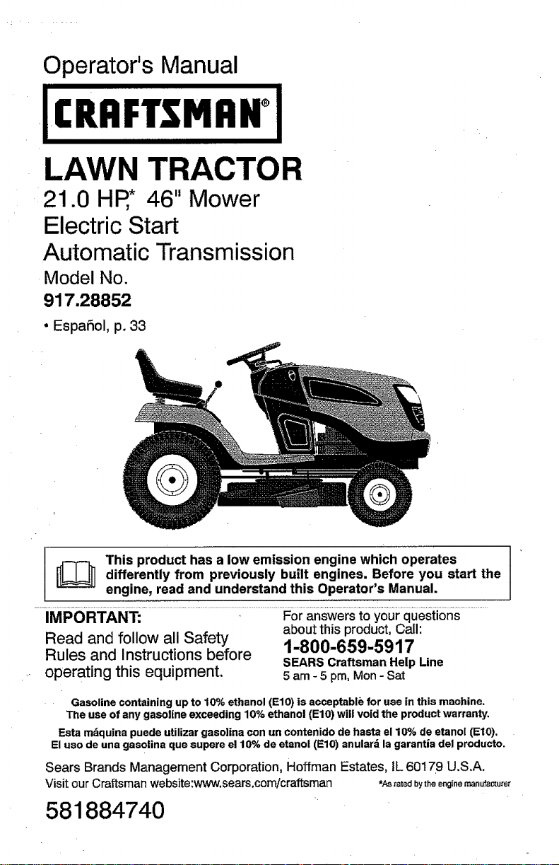
Operator's Manual
LAWN TRACTOR
21.0 HP,* 46" Mower
Electric Start
Automatic Transmission
Model No.
917.28852
° Espa_ol, p. 33
ThiSdifferentlyprOducthaSpreviouslyalow emission engines,enginewhich operates I '
engine, read and understand this Operator's Manual.
IMPORTANT: For answers to your questions
Read and follow all Safety about this product, Call:
Rules and Instructions before 1-800-659-5917
operating this equipment, 5 am - 5 pm, Mon - Sat
Gasoline containing up to 10% ethanol (EIO) is acceptable for use in this machine.
The use of any gasoline exceeding 10% ethanol (EIO) will void the product warranty,
Esta mdquina puede utilizar gaso]ina con un contenido de hasta el 10% de etanol (El0),
El uso de una gasolina que supere el 10% de etanol (EIO) anulard la garantia del producto.
Sears Brands Management Corporation, Hoffman Estates, IL 60179 U.S,A,
Visit our Craftsman website:www, sears.comicraftsman *Astat_ bytheengineraanufactu_'er
from built Before start the
SEARS Craftsman Help Line
you
l
581884740
Page 2

Warranty .................................................. 2
Safety Rules ............................................ 3
Product Specifications ............................. 6
Assembly/Pre-Operation ......................... 7
Operation ................................................. 9
Maintenance Schedule .......................... 16
Maintenance .......................................... 16
Service and Adjustments ....................... 2t
Storage .................................................. 27
Troubleshooting ..................................... 28
Sears Service ......................... Back Cover
Craftsman Riding Equipment Warranty
CRAFTSMAN FULL WARRANTY
FOR TWO YEARS fromthe date of purchase, all non-expendable parts of this riding equipment are
warranted against any defects in material or workmanship. A defective non-expendable part will
receive free in-home repair or replacement if repair is impossible.
FOR FiVE YEARS from the date of purchase, the frame and front axle of this riding equipment are
warranted against any defects in material or workmanship. A defective frame or front axle will receive
free in-home repair orreplacement if repair is impossible,
FOR 90 DAYS from the date of purchase, the battery (an expendable part) of this riding equipment
is warranted against any defects in material or workmanship (our testing proves that it wilt not hold a
charge). A defective battery will receive free in-home replacement.
ADDITIONAL LIFETIME LIMITED WARRANTY on CAST IRON FRONT AXLE (if equipped)
FOR AS LONG AS tT iS USED by the original owner after the fifth year from the date of purchase, the
cast ironfront axle (if equipped) of this riding equipment iswarranted against any defects in matedal or
workmanship. With proof of purchase, adefective cast front axtewill receive free in-home replacement,
WARRANTY SERVICE
For warranty coverage details to obtain free repair or replacement, call 1-800-659-5917 or visitthe
web site: www.craftsman.com
In all cases above, if part repair or replacement isimpossible, the riding equipment will be replaced
free of charge with the same or an equivalent model.
All of the above warranty coverage is void if this riding equipment is ever used while providing
commercial services or if rented to another person.
This warranty covers ONLY defects in material and workmanship. Warranty coverage does NOT
include:
• Expendable parts (except battery) that can wear out from normal use within the warranty period,
includingbut not limited to blades, spark plugs, air cleaners, belts, and oil filters.
• Standard maintenance servicing, oit changes, or tune-ups,
° Tire replacement or repair caused by punctures from outside objects, such as nails, thorns,
.....st=umps_or g!ass_........................................................................................
• Tire or wheel replacement or repair resulting from normal wear, accident, or improper operation or
maintenance.
• Repairs necessary because of operator abuse, including but not limited to damage caused by
towing objects beyond the capability of the dding equipment, impacting objects that bend the
frame, axle assembly or crankshaft, or over-speeding the engine.
• Repairs necessary because of operator negligence, includingbut not limited to, electrical and
mechanical damage caused by improper storage, failure to use the proper grade and amount
of engine oiJ,failure to keep the deck clear of flammable debris, orfailure to maintain the riding
equipment according to the instructions contained in the operator's manual.
• Engine (fuel system) cleaning or repairs caused byfuel determined to be contaminated oroxidized
(stale). in general, fuel should be used within 30 days of its purchase date.
• Normal deterioration and wear of the exterior finishes, or product label replacement,
This warranty gives you specific legal rights, and you may also have other rights which.vary from
state to state.
Sears Brands Management Corporation, Hoffman Estates, IL 60179
2
Page 3
_DANGER: This cutting machine is capable of amputating hands and feet and
throwing objects. Failure to observe the following safety instructions could result
in serious injury or death.
_WARNING: in order to prevent acciden-
tal starting when setting up, transporting,
adjusting or making repairs, a[ways discon-
nect spark plug wire and place wire where
it cannot contact spark plug.
_.WARNING: Do not coast down a hill in
neutral, you may lose control of the tractor.
_WARNING: Tow only the attachments
that are recommended by and comply with
specifications of the manufacturer of your
tractor. Use common sense when towing.
Operate only at the lowest possible speed
when ona slope. Too heavy of a load, while
on a slope, is dangerous. Tires can lose
traction with the ground and cause you to
lose control of your tractor.
_:_.WARNING: Engine exhaust, some of
its constituents, andcertain vehicle compo-
nents contain or emit chemicals known to
the State of California to cause cancer and
birth defects or other reproductive harm.
,_I_WARNING: Battery posts, terminals and
related accessories contain lead and lead
compounds, chemicals knowntotheState of
California to cause cancer and birth defects
or other reproductive harm. Wash hands
after handling.
I, GENERAL OPERATION
• Read, understand, and follow all instruc-
tions on the machine and in the manual
before starting.
• Do not put hands or feet near rotating . .
_arts or under the machine Keen clear " Followthe manuTacturer's recommenda-
.............of the discharge opening at'all times. .......,.................................. i......... T
• Only allow responsible adults, who are
familiar with the instructions,to operate
the machine.
Clear thearea of objects such as rocks,
toys, wire, etc., which could be picked
up and thrown by the blades.
• Be sure the area is clear of bystanders
before operating. Stop machineifanyone
enters the area.
• Never carry passengers.
• Do notmow in reverse unless absolutely
necessary. Always lookdown and behind
before and while backing.
_ B0nforwheelweights orco unterwelghts
• Never direct discharged material toward
anyone. Avoid discharging material
against a wall or obstruction. Material
may ricochet back toward the operator.
Stop the blades when crossing gravel
surfaces.
• Do not operate machine without the en-
tire grass catcher, discharge chute, or
other safetydevices in placeand working.
• Slow down before turning.
• Never leave a running machine unat-
tended. Always turn off blades, set
• parkingbrake, stop engine, and remove
keys before dismounting.
, Disengage blades when not mowing.
Shut off engine and wait for all parts to
come to a complete stop before cleaning
the machine,removing the grass catcher,
or unclogging the discharge chute.
• Operate machine only indaylight or good
artificial light.
• Do not operate the machine while under
the influence of alcohol or drugs.
• Watch for traffic when operating near or
crossing roadways.
• Use extracare when loadingorunloading
the machine intoa trailer or truck.
• Always wear eyeprotection when operat-
ing machine.
• Data indicates that operators, age 60
years and above, are involved in a large
percentage of riding mower-related inju-
ries. These operators should evaluate
their ability to operate the riding mower
safely enough to protect themselves and
others from serious injury.
Keep machine free of grass, leaves or
other debris build-up which cantouch hot
exhaust/engine parts and burn. Do not
allow the mower to plow leaves or other
debris which can cause build-up to oc-
cur.Clean any oil or fuel spillage before
operating or storing the machine. Allow
machine to cool before storage.
Page 4

!i.SLOPE OPERATION
Slopes are a major factor related to loss of
control and tip-over accidents, which can
result in severe injury or death. Operation
on all slopes requires extra caution. If you
cannot back upthe slope or ifyou feel uneasy
on it, do not mow it.
• Mow up and down slopes, not across.
• Watch for holes, ruts, bumps, rocks, or
other hidden objects. Uneven terrain
could overturn the machine, Tall grass
can hide obstacles.
• Choose a low ground speed so that you
will not have to stop or shift while on the
slope.
° Do not mow onwet grass. Tires may lose
traction.
Always keep the machine in gear when
going down slopes, Do notshiftto neutral
and coast downhill.
° Avoid starting, stopping, or turning on a
slope. Ifthetireslosetraction, disengage
the blades and proceed slowly straight
down the slope.
• Keep alt movement on the slopes slow
and gradual, Do not make sudden
changes in speed or direction, which
could cause the machine to roll over.
• Use extra care while operating machine
with grass catchers orother attachments;
they can affect the stability of the ma-
chine, Do no use on steep slopes.
• Do not try to stabilize the machine by
putting your foot on the ground.
• Do not mow near drop-offs, ditches,
or embankments. The machine could
suddenly roll over if a wheel is over the
edge or if the edge caves in.
I!1. CHILDREN
-_.WARNING: CHILDRENCANBEINJURED...............Extinguish all cigarettes; cigars_.pipes,.......
BYTHIS EQUIPMENT.The American Acade- and other sources of ignition.
my of Pediatrics recommends that children
be a minimum of 12 year of age before op-
erating a pedestrian controlled lawn mower
and a minimum of 16 years of age before
operating a riding lawn mower.
Tragic accidents can occur if the operator
is not alert to the presence of children.
Children are often attracted to the machine
and the mowing activity. Never assume
that children will remain where you last
saw them,
° Keep children out of the mowing area
and inthe watchful care of a responsible
adult other than the operator.
• Be alert and turn machine off if a child
enters the area.
• Before and while backing, look behind
and down for small children,
• Never carry children, even withthe blades
shutoff. They mayfall offand beseriously
injured or interfere with safe machine
operation. Children who have been given
rides inthe past may suddenly appear in
the mowing area for another rideand be
runover or backed over by the machine.
• Never allow children to operate the ma-
chine.
• Use extra care when approaching blind
corners, shrubs, trees, or other objects
that may block your view of a child,
IV. TOWING
t Tow only with a machine that has a hitch
designed for towing, Do notattach towed
equipment except at the hitch point.
• Followthe manufacturer's recommenda-
tion for weight limitsfortowed equipment
and towing on slopes.
• Never allow children or others in or on
towed equipment,
• On slopes, the weightofthe towedequip-
ment may cause loss oftraction and loss
of control.
• Travel slowly and allow extra distance to
stop.
V. SERVICE
SAFE HANDLING OF GASOLINE
To avoid personal injury or property dam-
age, use extreme care in handling gasoline.
Gasoline is extremely flammable and the
vapors are explosive.
• Use only approved gasoline container.
• Never remove gas cap or add fuel with
the engine running. Allow engine to cool
before refueling.
• Never fuel the machine indoors.
• Never store the machine orfuel container
where there is an open flame, spark, or
pilot lightsuch as on a water heater or
other appliances.
• Never fill containers insidea vehicle or
on atruck or trailer bed with plastic liner,
Always place containers on the ground
away from your Vehiclewhen filling.
Page 5
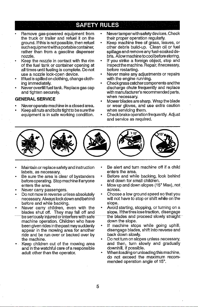
• Removegas-poweredequipmentfrom
thetruckortrailerandrefuelitonthe
ground.Ifthisisnotpossible,thenrefuel
suchequipmentwifhaportablecontainer,
ratherthanfromagasolinedispenser
nozzle.
• Keepthenozzleincontactwiththerim
ofthefueltankorcontaineropeningat
alltimesuntilfuelingiscomplete.Donot
useanozzlelock-opendevice.
- Iffuelisspilledonclothing,changecloth-
ingimmediately.
• Neveroverfillfueltank.Replacegascap
andtightensecurely.
GENERAL SERVICE
• Never operate machine in aclosed area,
• Keep allnuts and boltstightto besurethe
equipment is in safe working condition.
• Nevertamperwith safetydevices. Check
their proper operation regularly.
• Keep machine free of grass, leaves, or
other debris build-up, Clean oil or fuel
spillageand remove anyfuel-soaked de-
bris. Allow machineto cool beforestoring.
• If you strike a foreign object, stop and
inspectthe machine. Repair,ifnecessary,
before restarting.
• Never make any adjustments or repairs
with the engine running.
• Checkgrass catcher components andthe
discharge chute frequently and replace
with manufacturer's recommended parts,
when necessary.
- Mower blades aresharp, Wrap the blade
or wear gloves, and use extra caution
when servicing them,
• Check brake operation frequently. Adjust
and service as required.
• Maintain or replace safety and instruction
labels, as necessary.
• Be sure the area is clear of bystanders
beforeoperating. Stopmachine ifanyone
enters the area.
• Never carry passengers.
• Do not mow in reverse unlessabsolutely
necessary.Always lookdown and behind
before and while backing.
• Never carry children, even with the
blades shut off. They may fall off and
......beseriously injured or interfereWithsafe......................the blades and proceed slowly straight ....
machine operation. Children who have down the slope.
beengiven ridesinthe past maysuddenly
appear in the mowing area for another
ride and be run over or backed over by
the machine.
Keep children out of the mowing area
and in the watchful care of a responsible
adult other than the operator.
• Be alert and turn machine off if a child
enters the area,
° Before and while backing, look behind
and down for small children.
• Mow up and downslopes (15° Max), not
across.
• Choose a low ground speed so that you
will not have to stop or shift while on the
slope.
• Avoid starting, stopping, or turning on a
slope. ]fthetireslosetraction, disengage
• If machine stops while going uphill,
disengage blades, shift into reverse and
back down slowly.
• Do notturn on slopes unless necessary,
and then, turn slowly and gradually
downhill, if possible.
• When loading or unloading this machine,
do not exceed the maximum recom-
mended operation angle of 15°.
Page 6

PRODUCT SPECIFICATIONS
Gasoline Capacity 2.5 Gallons/9,46 L
and type: Regular Unleaded
Oil Type: SAE-30(above 32°F/0°C
(API: SG-SL) BAE 5W30 (below 32°F/0_C
Oil Capacity: W/Filter: 56 Oz./1,65 L
Spark Plug: Champion RC12YC
Charging 3 Amps Battery
System: 5 Amps Headlights
Battery: Amp/Hr: 28
Blade Bolt Torque: 45-55 Ft. LbsJ62-75 Nm
W/out Filter: 48 Oz./1,4 L
(Gap: .030"/0.76 mm)
Min. CCA: 230
Case size: UIR
CONGRATULATIONS onyour purchase of
a new tractor. It has been designed, engi-
neeredand manufacturedto giveyou the best
possible dependability and performance.
Shouldyou experience any problemyoucan-
not easily remedy, pleasecontact a Sears or
other qualified service center. We havecom-
petent, well-trained representatives and the
proper tools to service or repair this tractor.
Please read and retain this manual. The
instructions will enable you to assemble
and maintain your tractor properly, A_ways
observe the "SAFETY RULES",
Inthe state of California the aboveis required
bylaw (Section4442 ofthe California Public
Resources Code), Other states may have
similar laws. Federal taws apply on federal
lands. A spark arrester for the muffler is
availablethrough your nearestSearsservice
center (See REPAIR PARTS manual).
REPAIR PROTECTION AGREEMENTS
Congratulations on making a smart pur-
chase. Your new Craftsman® product is
designed and manufactured for years of
dependable operation. But like all products,
itmay require repair from timeto time. That's
when having a RepairProtection Agreement
can save you money and aggravation.
Purchase a Repair Protection Agreement
now and protect yourseff from unexpected
hassle and expense.
Here's what's included in the Agreement:
. Expert service byour 12,000professional
repair specialists.
• Unlimited service and nochargeforparts
and labor on all covered repairs.
• Product replacement if your covered
product can't be fixed.
• Discount of t0% from regular price of
service and service-related parts not
CUSTOMER RESPONSIBILITIES
• Read and observe the safety rules,
• Follow a regular schedule in maintaining,
caring for and using your tractor.
• Follow instructionsunder "Maintenance"
and "Storage" sections of this manual.
• Wear proper Personal Protective Equip-
ment (PPE) while operating this machine,
including (at a minimum) sturdy footwear,
eye protection, and hearing protection.
Do not mow in shorts and/or open toed
footwear.
,._--Aiwaysietsomeoneknowyouareoutside ...........speci.a!!sts, wing.have acces§ to g_e_ _5..
mowing.
Ai_WARNING: This tractor is equipped with
an internalcombustion engine and should
not be used on or near any unimproved
forest-covered, brush-covered or grass-
covered land unless the engine's exhaust
system is equipped with a spark arrestor
meeting applicable local or state laws (if
any). if a spark arrester is used, it should
be maintained ineffective working order by
the operator.
covered by the agreement; also, 10% off
regular price of preventive maintenance
check.
• Fast help by phone - phone support
from aSears representative on products
requiring in-home repair,plusconvenient
repair scheduling.
Once you purchase the Agreement, asimple
phone call isall that ittakes for youtOsched-
uleservice. Youcan callanytime dayor night,
or schedule a service appointment online.
Sears has over 12,000 professional repair
million quality parts andaccessones. That's
the kind of professionalism you cancount on
tohelp prolong the life of your new purchase
for years to come. Purchase your Repair
Protection Agreement today!
Some limitations and exclusions apply.
For prices and additional information call
1-800-827-6655,
SEARS INSTALLATION SERVICE
For Sears professional installation of home
appliances, garage door openers, water
heaters, and other major home items, inthe
U,S,A. call 1-800-4-MY-HOME®
Page 7
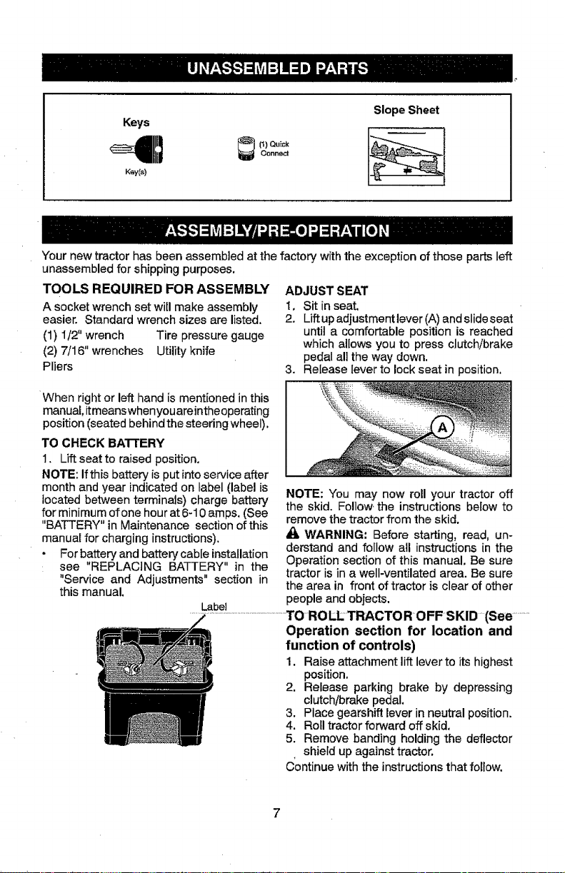
Keys
SlopeSheet
Your new tractor has been assemb]ed at the factory with the exception of those parts left
unassembled for shipping purposes,
TOOLS REQUIRED FOR ASSEMBLY
A socketwrench set will make assembly
easier. Standard wrench sizes are listed.
(1) 1/2" wrench Tire pressure gauge
(2) 7/16" wrenches Utility knife
Pliers
When right or left hand is mentioned inthis
manual,itmeanswhenyouareintheoperating
position (seated behind the steering wheel).
TO CHECK BATTERY
1. Lift seat to raised position.
NOTE: Ifthis battery is put into service after
month and year indicated on label (label is
located between terminals) charge battery
for minimum ofone hour at 6-10 amps. (See
"BATTERY" in Maintenance section of this
manual for charging instructions).
• For battery and battery cable installation
see "REPLACING BATTERY" in the
"Service and Adjustments" section in
this manual.
ADJUST SEAT
1, Sit in seat,
2. Lift upadjustment lever (A)and slide seat
until a comfortable position is reached
which allows you to press clutch/brake
pedal all the way down.
3. Release lever to lock seat in position,
NOTE: You may now roll your tractor off
the skid. Follow the instructions below to
remove the tractor from the skid.
_, WARNING: Before starting, read, un-
derstand and follow all instructions in the
Operation section of this manual. Be sure
tractor is in a well-ventilated area. Be sure
the area in front of tractor is clear of other
people and objects.
Operation section for location and
function of controls)
1. Raise attachment lift lever to its highest
position.
2. Release parking brake by depressing
clutchtbrake pedal.
3. Place gearshift leverin neutral position.
4. Roll tractor forward off skid.
5. Remove banding holding the deflector
, shield up against tractor.
Continue with the instructions that foltow.
Page 8

CHECK TIRE PRESSURE
Thetires onyour tractor were overinflated at
the factory for shipping purposes. Correct
tire pressure is important for best cutting
performance.
• Reduce tire pressure to PSI shown on
tires.
CHECK DECK LEVELNESS
For best cutting results, mower housing
should be properly leveled. See "TO LEVEL
MOWER" in the Service and Adjustments
section of this manual.
CHECK FOR PROPER POSITION OF
ALL BELTS
See the figures that are shown for replacing
motion and mower blade drive belts in the
ServiceandAdjustments section ofthis man-
ual. Verify thatthe belts are routed correctly.
CHECK BRAKE SYSTEM
After you learn how to operate your tractor,
check to see that the brake is operating
properly. See "TO CHECK BRAKE" in the
Service and Adjustments section of this
manual.
t/_CHECKLIST
Before you operate your new tractor, we
wish to assure that you receive the best
performance and satisfaction from this
Quality Product.
Please review the following checklist:
J" All assembly instructions have been
completed.
No remaining loose parts in carton.
_" Batteryis properlypreparedandcharged.
!/" Seat is adjusted comfortably and tight-
ened securely.
_/' All tires are properly inflated. (For ship-
ping purposes, thetires wereoverinflated
at the factory).
J' Be sure mower deck is properly leveled
side-to-side/front-to-rear for best cutting
results. (Tires must be properly inflated
for leveling).
!/Check mower and drive belts. Be sure
they are routed properly around pulleys
and inside all belt keepers.
1/" Check wiring. See that all connections
are still secure and wires are properly
clamped,
_/" Before driving tractor, be sure freewheel
control is in "transmission engaged"
position (see "TO TRANSPORT" in the
Operation section of this manual).
While learning howto useyour tractor,payex-
traattention to the following important items:
J" Engine oil is at proper level.
J" Fuel tank isfilledwith fresh, clean, regular
unleaded gasoline.
J" Become familiar with all controls, their
location and function. Operate them
before you start the engine.
!,/ Be sure brake system isinsafe operating
condition.
_--BesureOperator PresenceSystemand .........
Reverse Operation System (ROS) are
working properly (Seethe Operation and
Maintenance sections in this manual).
1/,. It is important to purge the transmission
before operating your tractor for the
first time. Follow proper starting and
transmission purging instructions (See
"TO START ENGINE" and "PURGE
TRANSMISSION" in the Operation sec-
tion of this manual).
.
Page 9

These symbols may appear on your tractor or in literature supplied with the product. Learn
and understand their meaning,
R N
REVERSE NEUTRAL
H L I' ,1
HIGH LOW CHOKE FAST SLOW
6
I_NGINE OFF REVERSE
UGHTS ON FUEL
ATTACHMENT ATTACHMENT DANGER, KEEP HANDS
CLUTCH DISFJ',IGAGED CLUTCH ENGAGED AND F-_ETAWAY
Failure to follow instructions
Could result in serious injury or
death. The safety aiert symbol
is used to identify safety inform-
ation about hazards which can
result in death, serious injury
and/or property damage,
OPERATION
SYSTEM (ROS t
FREE WHEEL
(Automatic Models only)
ENGINE ON ENGINE START PARKING BRAKE MOWER HEIGHT
BA31"ERY REVERSE FORWARD
IGNITION SWITCH
MOWER LIFT
C.0,SECONTROLCLUTC_SRAKE
PEDAL
®@@@@
KEEP AREA CLEAR SLOPE HAZARDS
(SEE SAFERY RULES SECTION)
DANGER indicates a hazard which, if not avoided,
will result in death or serious injury,
WARNING indicates a hazard which, if not avoided,
could result in death or serious injury.
CAUTION indicates a hazard which, if not avoided,
might result in minor or moderate injury.
CAUTION when used without the ale_ symbol,
indicates a situation that could result in damage
to the tractor and/or engine.
HOT SURFACES indicates a hazard which,
if not avoided, could result in death, serious injury
and/or property damage.
FIRE indicates a hazard which, if not avoided,
could result in death, serious injury and/or
property damage.
Page 10
KNOW YOUR TRACTOR
READ THIS MANUAL AND SAFE'rY RULES BEFORE OPERATING YOUR TRACTOR
Compare the illustrationswith your tractorto familiarize yourself withthe locations of
various controls and adjustments. Save this manual for future reference.
03078
Our tractors conformto the applicable safety standards of the
American National Standards Institute.
(A) ATTACHMENT LIFT LEVER - Used to
raise and lower the mower or other attach-
ments mounted to your tractor.
(B) CLUTCH/BRAKE PEDAL - Used for
deciutching and braking the tractor and
starting the engine.
(C) PARKING BRAKE- Locks clutch/brake
(F) IGNITION SWITCH - Used for starting
and stopping the engine.
(G) REVERSE OPERATION SYSTEM
(ROS) "ON" POSITION - Allows operation
ofmower orother powered attachment while
in reverse,
(H) LIGHT SWITCH - Turnsthe headlights
_pedal !r_to.th.e.brake p0sit!0n...............................................on arid .off.................................................................................
(D) THROTTLE/OHOKECONTROL-Used (J) MOTION CONTROL LEVER - Selects
for starting and controlling engine speed, the speed and direction of tractor,
(E) ATTACHMENTCLUTCHLEVER.Used (M) FREEWHEELOONTROL-Disengages
to engagethe mower blades, or other attach- transmission for pushing or slowlytowing the
ments mounted to your tractor, tractor with the engine off,
10
Page 11
The operation of any tractor can result in foreign objects thrown into
the eyes, which can result in severe eye damage. Always wear safety
glasses or eye shields while operating your tractor or performing any
adjustments or repairs. We recommend standard safety glasses or a
wide vision safety mask worn over spectacles.
HOW TO USE YOUR TRACTOR
TO SET PARKING BRAKE
Your tractor is equipped with an operator
presence sensing switch. When engine is
running, any attempt bythe operator to leave
the seatwithoutfirst settingthe parkingbrake
will shut off the engine.
1. Depress clutch/brake pedal (B) all the
way down and hold.
2. Pull parking brake lever (C) up and hold,
release pressure from clutch/brake pedal
(B),then release parking brakelever.Ped-
alshould remain in brakeposition, Ensure
parking brake will hold tractor secure,
STOPPING
MOWER BLADES -
• To stop mower blades, move attachment
clutch control to disengaged position(t_).
ENGINE -
• Move throttle control (D) to fast position.
NOTE: Failure to move throttlecontrol to fast
position before stopping may cause engine
to "backfire".
• Turn ignitionkey (F) to "STOP" position
andremove key.Always remove keywhen
leavingtractor to prevent unauthorized use.
• Never use choke to stop engine.
IMPORTANT: Leaving the ignition switch in
anyposition otherthan "STOP" will causethe
batteryto discharge and go dead,
NOTE:Under certain conditions when tractor
isstanding idlewith the engine running, hot
engine exhaust gases may cause "brown-
ing" of grass. To eliminate this possibility,
always stop engine when stopping tractor
on grass areas.
_, CAUTION: Always stop tractor com-
pletely, as described above, before leaving
the operator's position.
TO USE THROTTLE CONTROL (D)
Always operate engine at full speed (fast).
• Operating engine at less than full speed
(fast)reducesengine'soperatingefficiency,
• Full speed (fast) offers the best mower
performance.
"_ Clutch Control -' Clutch Control
"Engaged.... Disengaged"
GROUND DRIVE -
• Tostop ground drive,depress brakepedal
all the way down.
• Move motion control lever to neutral
position.
11
Page 12
TO MOVE FORWARD AND
BACKWARD
The direction and speed of movement is
controlled by the motion control lever. (J)
1. Start tractor with motion control lever in
neutral position.
2. Release parking brake.
3. Slowly move motion control lever to
desired position.
TO ADJUST MOWER CUTTING HEIGHT
The position of the attachment lift lever (A)
determines the cutting height,
• Put attachment lift lever in desired cutting on rough, rolling terrain or hills,
height slot. 1. Select desired height of cut with attach-
• Slidepointertab(T)todesiredcuttingheight 2. Start mower blades by engaging attach-
as a reminder for next time you mow. merit clutch control.
The cutting height range isapproximately I" Tn -_Tt_D Mnw_ .....
-t-64":TheheightS are measured ftomtfi6 ........E)?isen_a'uea'_ac"" DL_U,,-_ ...........T-;........................
groundto the bladetip withthe engine notrun- Zk
ning,Theseheightsareapproximateandmay _OAUTION" Do not operate the mower
vary depending upon soil conditions, height
of grass and types of grass being mowed.
• The average lawn should be cut to ap-
proximately 2-1/2" duringthe cool season
and to over 3" during hot months. For
healthier and better looking lawns, mow
often and after moderate growth.
• For best cutting performance, grass over
6" in height should be mowedtwice. Make
the first cut relatively high; the second to
desired height.
TO ADJUST GAUGE WHEELS
Gauge wheels are properly adjusted when
they are slightly off the ground when mower
is at the desired cutting height in operating
position. Gauge wheels then keep the deck
m proper position to help prevent scalping
in most terrain conditions.
NOTE: Adjust gauge wheels with tractor on
aflat level surface.
I. Adjust mower to desired cutting height
(See "TO ADJUST MOWER CUTTING
HEIGHT" in this section of manual).
2. With mower indesired height of cut posi-
tion, gauge wheels should be assembled
so they are slightly offthe ground. Install
gauge wheel inappropriate hole. Tighten
securely.
3. Repeat for all, installing gauge wheel in
same adjustment hole.
TO OPERATE MOWER
Your tractor is equipped with an operator
presence sensing switch. Any attempt
by the operator to leave the seat with the
engine running and the attachment clutch
engaged will shut off the engine. You must
remain fully and centrally positioned in the
seat to prevent theengine from hesitating or
cutting off when operating your equipment
ment liftlever.
g g _ nmentclu[cn control
without either the entire grass catcher, on
mowers so equipped, or the deflector shield
(S) in place.
12
Page 13

REVERSE OPERATION SYSTEM (ROS)
Your tractor is equipped with a Reverse
Operation System (ROS). Any attempt by
the operator to travel inthe reverse direction
with the attachment clutch engaged will shut
off the engine unless ignition key is placed
in the ROS "ON" position,
_WARNING: Backing up with the at-
tachment clutch engaged while mowing is
strongly discouraged. _Jrningthe ROS"ON",
to allow reverse operation with the attach-
ment clutch engaged, should only be done
when the operator decides itis necessary to
reposition the machine with the attachment
engaged. Do not mow in reverse unless
absolutely necessary.
USING THE REVERSE OPERATION
SYSTEM -
Only useifyou arecertain nochildren orother
bystanders will enter the mowing area.
1. Move motion control lever to neutral
position.
2. With engine running, turn ignition key
counterclockwise to ROS "ON" posi-
tion.
3. Look down and behind before and while
backing.
4. Slowly move motion control lever to
reverse (R) position to start movement,
5. When useofthe ROS isnolonger needed,
turnthe ignition key clockwise to engine
"ON" position.
ROS "ON" Position
Engine "ON" Position
{Normal Operating)
IMPORTANT: The motion control lever does
not returnto neutral positionwhenthe clutch/
brake pedal is depressed.
• To restart movement, slowly release park-
ing brake and clutch/brake pedal.
• Slowly move motion control lever to slow-
est setting.
• Make all turns slowly.
TO TRANSPORT
When pushing or towing your tractor, En-
sure to disengage transmission by placing
freewheel control in freewheel!rig position.
Freewheel control is located at the rear
drawbar of tractor.
1. Raise attachment lift lever to its highest
position.
2. Pullfreewheel control outand intothe slot
and release soit isheld inthe disengaged
position.
• Do not push or tow tractor at more than
two (2) MPH.
• Tore-engage transmission, reverseabove
procedure.
TRANSMISSION ENGAGED
TRANSMISSION DISENGAGED
NOTE: To protect hood from damage when
transporting your tractor onatruck or atrailer,
Ensurehood isclosed and secured totractor.
Use an appropriate means of tying hood to
tractor (rope, cord, etc.).
-=TO-OPERATEONHILLS .................................................................................._TQ'_tlNG.CARTSAND OTHER.A37rAC.H.....
_:_IkWARNING: Do not drive up or clown MENTS
hillswith slopes greater than 15° and do not mended by and comply with specifications
drive across any slope. Use the slope guide
provided at the back of this manual,
• Choose the slowest speed before starting
up or down hills.
° Avoid stopping or changing speed on
hills.
Tow only the attachments that are recom-
of the manufacturer of your tractor. Use
common sense when towing. Too heavy of
aload, while on aslope, is dangerous. Tires
can lose traction with the ground and cause
you to lose control of your tractor.
• If stopping is absolutely necessary, push
clutch/brake pedatquicklyto brakeposition
and engage parking brake.
• Move motion control lever to neutral posi- "
tion.
13
Page 14
BEFORE STARTING THE ENGINE
CHECK ENGINE OIL LEVEL
The enginein your tractor hasbeen shipped,
from the factory, already filled with summer
weight oil,
1. Check engine oil with tractor on level
ground.
2. Remove oil fill cap/dipstick and wipe
clean, reinsert the dipstick and screw cap
tight, wait for afew seconds, remove and
read oil level. If necessary, add oil until
"FUL_ mark on dipstick is reached. Do
not overfill.
• For cold weather operation you should
change oil for easier starting (See the oil
viscosity chart inthe Maintenance section
of this manual).
• Tochangeengine oil,seethe Maintenance
section in this manual,
ADD GASOLINE
o Fill fuel tank to bottom offifter neck. Do not
overfill. Usefresh, clean, regular unleaded
gasoline with a minimum of 87 octane.
(Use of leaded gasoline will increase
carbonand lead oxide depositsand reduce
valve life). Do not mix oil with gasoline.
Purchasefuel inquantities thatcan beused
within 30 days to ensure fuel freshness.
_CAUTION: Wipe offany spilled oil orfuel.
Do not store, spill or use gasoline near an
open flame.
IMPORTANT: When operating in tem-
peratures below 32°F(0°C), use fresh, clean
winter grade gasoline to help ensure good
cold weather starting.
CAUTION: Alcohol blended fuels (called
gasohol or using ethanol or methanol) can
attract moisture which leads to separation
andformation ofacids during storage, Acidic
gascan damage the fuel system of anengine
while in storage. Toavoid engine problems,
the fuel system should be emptied before 1. Ensure the tractor is on level ground.
storage of 30 days or Ionqer, Drain the gas 2. Place the motion control leverin neutral.
fuellinesandcarburetorareempty. Usefresh clutch/brake slowly return to operating
fuel next season. See Storage Instructions position.
foradditional information. Never useengine
or carburetor cleaner products inthefueltank
or permanent damage may occur.
TO START ENGINE
When starting the engine for the first time or
if the engine has run out of fuel, it will take
extra cranking time to move fuel from the
tank to the engine.
I, Ensure freewheel control is in the trans-
mission engaged position.
2. Siton seat in operating position, depress
clutch/brake pedaland set parkingbrake.
3. Place motion control lever in neutral
position.
4. Move attachment clutch to disengaged
position.
5. Move throttle control to choke position.
NOTE: Before starting, read the warm and
cold starting procedures below.
6. Insert key into ignition and turn key
clockwise to start positionand release
key as soon as engine starts, Do not run
starter continuously for more than fifteen
seconds per minute. If the engine does
not start after several attempts, move
throttle control to fast position, wait a
few minutes and try again. Ifengine still
does not start, move the throttle control
back to the choke position and retry.
WARM WEATHER STARTING
(50°F/10°C and above)
7. When engine starts, move the throttle
control to the fast position.
• The attachments and ground drive can
nowbe used, tftheengine does notaccept
the load, restart the engine and allow itto
warm up for one minute using the choke
as described above.
COLD WEATHER STARTING
(50°F/10°C and below)
7. When engine starts, leavethrottle control
in choke position until engine warms up
and begins to run roughly, Once rough
running begins, immediately move the
throttle controlto the fast position. Engine
warm-up maytake from several seconds
to several minutes (the colder the tem-
perature, the longer the warm-up).
AUTOMATIC TRANSMISSION WARM UP
Before driving the unit in cold weather, the
transmissionshould bewarmedupasfollows:
3. AUowoneminutefor transmissiontowarm
up. This can be done during the engine
warm up period.
• The attachments can also be used dur-
ing the engine warm-up period after the
transmission has been warmed up.
NOTE: Ifat ahigh altitude (above 3000feet)
or in cold temperatures (below 32°F/0°C)
the carburetor fuel mixture may needto be
adjusted for best engine performance (see
"TOADJUST CARBURETOR" inthe Service
and Adjustments section of this manual).
14
Page 15
PURGE TRANSMISSION
_CAUTION: Never engageordisengage
freewheel lever while the engine is running.
Toensure proper operation and performance,
it is recommended that the transmission be
purged before operating tractor for the first
time.This procedure will removeanytrapped
air inside the transmission which may have
developed during shipping of yourtractor.
IMPORTANT: Should your transmission
require removal for service or replacement,
itshould bepurged after reinstallation before
operating the tractor.
1, Place tractor safely on a level surface -
that is clear of objects and open - with
engine off and parking brake set.
2. Disengage transmission by placing
freewheel control indisengaged position
(See "TO TRANSPORT" inthis section
of manual).
3. Sitting in the tractor seat, start engine.
After the engine isrunning, move throttle
control to slow position. With motion
control lever in neutral position, slowly
disengage clutch!brake pedal.
A_JLCAUTION:At any time, during step 4,
there may be movement ofthe drive wheels,
4, Move motion control leverto full forward
position and hold for five (5) seconds,
Move lever to full reverse position and
hold for five (5) seconds, Repeat this
procedurethree (3) times,
5. Move motion control lever to neutral
position. Shutoff engine and set parking
brake.
6. Engage transmission by placing free-
wheel control in engaged position (See
"TO TRANSPORT" in this section of
manual),
7. Sitting in the tractor seat, start engine.
After the engine isrunning, movethrottle nn np.rfnrmance and nroner discharae
controlto half (t/2) speed With motion .-_ r-,.----, r r o
.............. '...................... of-material: Regulategrour_d speedby .........
control lever in neutral position, slowly
disengage clutch!brake pedal.
8. Slowlymove motion controlleverforward,
after the tractor moves approximately
five (5)feet, slowly move motion control
leverto reverse position. After thetractor
moves approximately five (5) feet return
the motion control lever to the neutral
position. Repeat this procedure with the
motion control lever three (3)times.
Your transmission is now purged and now
ready for normal operation.
MOWING TIPS
* Tire chains cannot be used when the
mower housing is attached to tractor.
. Mowershould beproperlyleveled for best
mowing performance, See "TO LEVEL
MOWER HOUSING" in the Service and
Adjustments section of this manual.
* The left hand side of mower should be
used for trimming.
* Drivesothat clippings are discharged onto
the area that has already been cut. Have
the cutarea to the rightof thetractor. This
will result in a more even distribution of
clippings and more uniform cutting.
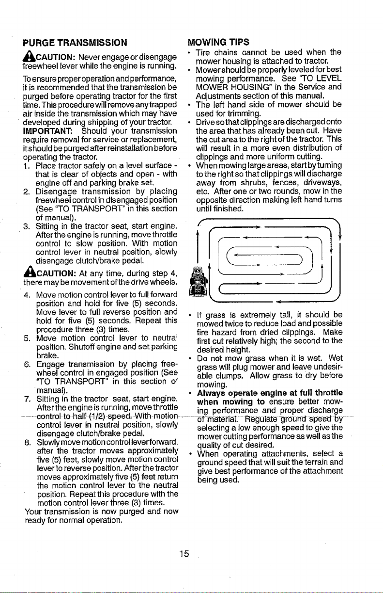
° When mowinglarge areas, startbyturning
tothe right so that clippings will discharge
away from shrubs, fences, driveways,
etc. After one or two rounds, mow in the
opposite direction making left hand turns
until finished.
• If grass is extremely tall, it should be
mowed twice to reduce load and possible
fire hazard from dried clippings. Make
first cut relatively high; the second to the
desired height.
• Do not mow grass when it is wet. Wet
grass will plug mower and leave undesir-
able clumps. Allow grass to dry before
mowing.
• Always operate engine at full throttle
when mowing to ensure better mow-
selecting a tow enough speed to give the
mower cutting performance as well as the
quality of cut desired.
* When operating attachments, select a
ground speed that will suit the terrain and
give best performance of the attachment
being used.
15
Page 16

MAINTENANCE SEWOR_
SCHEDULE SAC.
Cheek Brake O_er'a_fon V F
Chee,k Tire Pressure
aT Check Operator Presence & P,OS Systems
A Cheek for Loose Fasteners V f
C Chec_Replaee Mower Blades
T LubriBation Chart
0 Cheek Batt_t_ Leve!
R clean Battetv and Terminals
Clean Debris Off Steering Plate
Cheek Tra_saxle Coo,l!t_g
Cheek Mower Levelness
Check V-Be_ts
C,heek Engine Oii Level V*
Chat_qe Enqine Oil (w!th oil filter)
Ch_ng_ Engine Oil (withQul _iI !!!t_r)
E Clean Air Filter
G Clean Air Semen
I Inspect Muffler,/Spark Arrester
U RepIsce 0il tilter (If equipped)
E Clean Engine Cooling Fins
Replace Spark PZu9
Repines Ai_ Filt e_" Paper Car t_'idge
Rept_,tce Fuel Filter
EVERY EVERY EVERY EVERY EVEW¢ BEFORE
USE
B 2,5 50 100 SEASON BTORAGE
HOURB HOURS HOURS HOURS
v"
v'
V= ........................
V
=/ v'
V_5 .........................
v"
v'
V_,,
ii ii ii iiiiiiiiiiiiiiiii iiiiiiiv'
v',,= v'
v'.
v',
_L_, _.....
i/ ,v"..........
v',
iii iii iiii
v"
GENERAL RECO MMENDATIONS LUBRICATIONCHART
The warranty onthis tractordoes not cover
items that have been subjected to operator _\ " "
_)SteenngPivotBolts
abuse or negligence. To receive full value • Spindle_f_/L_'_r_ Spindle
from the warranty, operator must maintain Zerk I_1! / \ _1_ Zerk -
tractor as instructed in this manual, _J__IP_,--I_
Some adjustments wiBneedto bemade pe- d)Fr°ntJl- LZ=I!_o \\" II2"J_"_'_ Front
riodically toproperly maintain your tractor, - • ,_;__.__.'_ _/heeI
Wheel
At least once a season, check to see if _Te_knng _ ..... _'_-_\ Bearing
you should make any of the adjustments ._/I _ IX,,"7 Zerk
described in the Service and Adjustments (D Steerin.qj _ ,.-__'_'_
section of this manual. Sector [ ( t_-_' 'I 1 \x_.
_';-At le_t once a year youshould replace.................................Ge ngine..........
the spark plug, clean or replace air filter, Teeth I i ,\ '-_. J, ] I
and check blades and belts for wear, A _-_ <--_
new spark plugandclean air filter assure
proper air-fuel mixture and help your en-
gine run better and last longer,
(DGeneral Purpose Grease
@Refer to Maintenance "ENGINE" Section
BEFORE EACH USE
1. Check engine oillevel.
2. Check brake operation.
3, Check tire pressure,
4. Check operator presence and
ROS systems for proper operation,
5. Check for loose fasteners.
IMPORTANT: Do not oilor grease the pivot
points which have special nylon bearings.
Viscous lubricants wilt attract dust and dirt
thatwill shorten the lifeof the self-lubricating
bearings, Ifyou feelthey must belubricated,
use only a dry, powdered graphite type lu-
bricant sparingly.
16
Page 17
TRACTOR
Alwaysobservesafetyruleswhenperforming
anymaintenance.
BRAKE OPERATION
tf tractor requires more than five (5) feet to
stop at highest speed in highest gear on a
level, dr:/concrete or paved surface, then
brake must be serviced. (See "TO CHECK
BRAKE" in the Service and Adjustments
section of this manual).
TIRES
• Maintain proper air pressure in all tires
(See the sides of tires for proper PSI).
• Keep tires free of gasoline, oil, or insect
control chemicals which can harm rubber.
• Avoid stumps, stones, deep ruts, sharp
objects and other hazards that may cause
tire damage.
NOTE: To seal tire punctures and prevent
flat tires due to slow leaks, tire sealant may
be purchased from your local parts dealer.
Tire sealant also prevents tire dry rot and
corrosion.
OPERATOR PRESENCE SYSTEM AND
REVERSE OPERATION SYSTEM (ROS)
Ensure operator presence and reverse
operation systems are working properly. If
your tractor does not 1unction as described,
repair the problem immediately.
°
The engine should not start unless the
brake pedal is fully depressed, and the
attachment clutch control is in the disen-
gaged position.
CHECK OPERATOR PRESENCE
SYSTEM
• When the engine is running, any attempt
bythe Operatorto leave the seat without
first setting the parking brake should shut
off the engine.
• When the engine is running and the at-
tachment clutch is engaged, any attempt
by the operator to leave the seat should
• The attachment clutch should never oper-
ate unless the operator is in the seat.
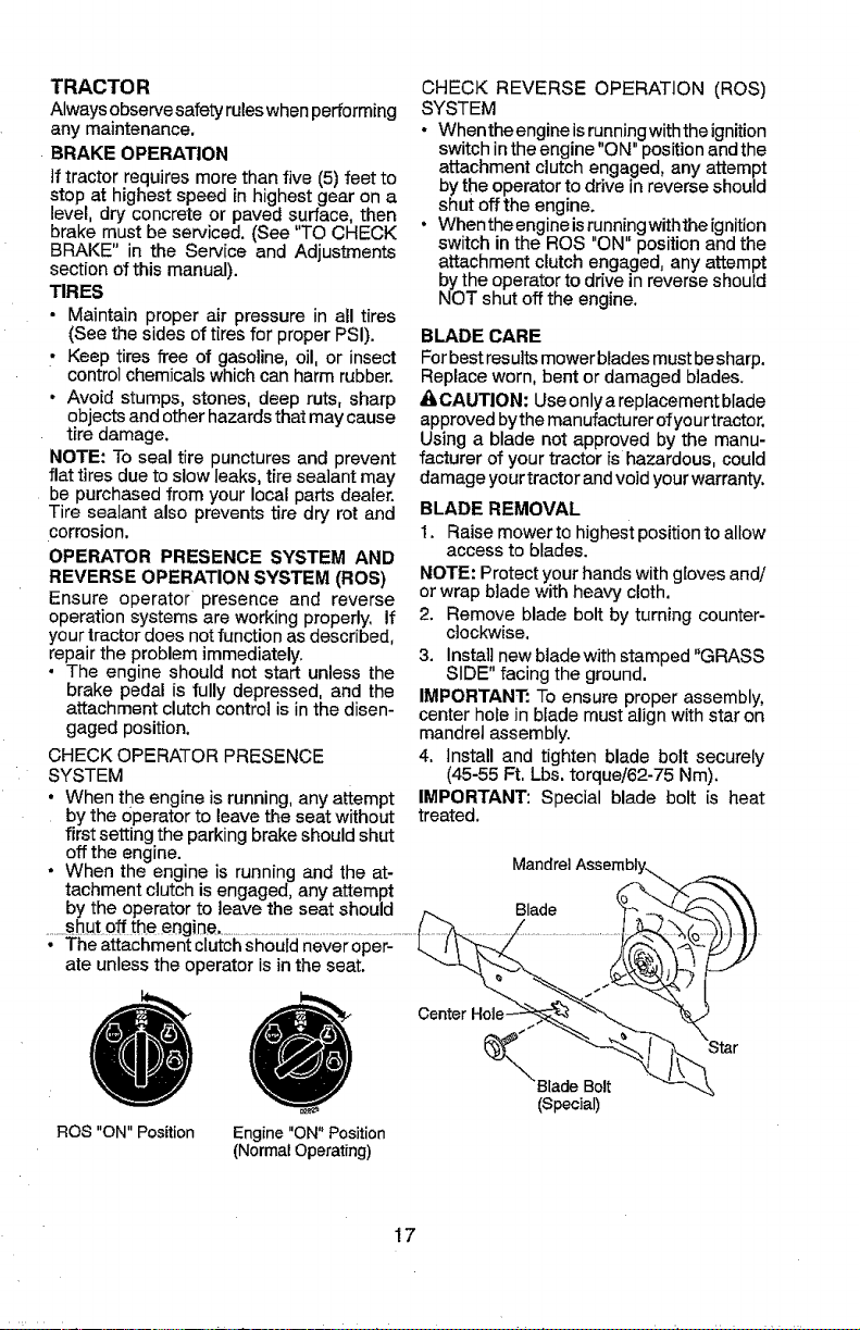
CHECK REVERSE OPERATION (ROS)
SYSTEM
° Whenthe engine is runningwith the ignition
switch in the engine "ON" position andthe
attachmentclutch engaged, any attempt
bythe operator to drive in reverse should
shut off the engine.
° Whenthe engine isr,unn!ngwiththe ignition
switch in the ROS ON position and the
attachment clutch engaged, any attempt
by the operator to drive in reverse should
NOT shut off the engine.
BLADE CARE
Forbestresults mower blades must besharp.
Replace worn, bent or damaged blades.
&CAUTION: Useonlya replacement blade
approved bythe manufacturer ofyour tractor.
Using a blade not approved by the manu-
facturer of your tractor Is hazardous, could
damage your tractor andvoid your warranty.
BLADE REMOVAL
1. Raise mower to highest position to allow
access to blades.
NOTE; Protect your hands with gloves and/
or wrap blade with heavy cloth.
2. Remove blade bolt by turning counter-
clockwise.
3. Install new blade with stamped "GRASS
SIDE" facing the ground.
IMPORTANT: To ensure proper assembly,
center hole in blade must align with star on
mandrel assembly.
4. Install and tighten blade bolt securely
(45-55 Ft. Lbs. torque/62-75 Nm).
IMPORTANT: Special blade bolt is heat
treated.
ROS "ON" Position Engine "ON" Position
(Normal Operating)
Center Hole-
(_i'Blade Bolt
(Special)
17
Page 18

BATTERY
Your tractor has a batter_jcharging system
which is sufficient for normal use, However,
periodic charging of the battery with .an au-
tomotive charger willextend its life.
Keep battery and terminals clean.
Keep battery bolts tight,
• Keep small vent holes open.
• Recharge at 6-10 amperes for 1 hour.
ENGINE
LUBRICATION
Only use high quality detergent oil rated with
APt service classification SG-SL. Selectthe
oil's SAE viscosity grade according to your
expected operating temperature.
$AE V_SCOS£_Y GRAD:ES
NOTE: The original equipment battery on
your tractor is maintenance free, Do not
attempt to open or remove caps or covers.
Adding or checking level of electrolyte is
not necessary.
TO CLEAN BATTERY AND TERMINALS
Corrosion and dirt on the battery and termi-
nals can cause the battery to "leak" power.
1. Disconnect BLACK battery cable first
then RED battery cable and remove
battery from tractor,
2. Rinse the battery with plainwater anddry,
3. Clean terminals and battery cable ends
with wire brush until bright.
4. Coat terminals with grease or petroleum
i_lly.
5. Reinstafi battery (See "REPLACING
BATTERY" in the SERVICE AND AD-
JUSTMENTS section of this manual).
V-BELTS
CheckV-belts for deterioration andwear after
t00 hours ofoperation and replace ifneces-
sary. The belts are not adjustable. Replace
belts if they begin to slip from wear.
TRANSAXLE COOLING
The transmission fan andcooling finsshould
be kept dean to ensure proper cooling_
Do not attempt to clean fan or transmission
while engine is running or while the trans-
mission is hot, To prevent possible damage
to seals, do not use high pressure water or
steam to clean transaxle.
• Inspect cooling fan to Ensure fan blades
are intactand clean.
C -_ -s0 -to _ 1o 2g _o 40
_"EMp ERATU'RERANGE ANTIC _'PATED_"OR E N_T OIL C_*NG_
NOTE: Although multi-viscosity oils(5W30,
10W30etc.) improve starting in cold weather,
they will result in increased oil consumption
when used above 32°F/0°C. Check your
engine oil level more frequentlyto avoid pos-
sible engine damage from running low onoil.
Change the oil after every 50 hoursof opera-
tion or at least once a year ifthe tractor is
not used for 50 hours in one year.
Check the crankcase oil level before starting
the engine and after each eight (8) hours
of operation. Tighten oil fill cap/dipstick
securely each time you check the oil level.
TO CHANGE ENGINE OIL
Determine temperature range expected
before oil change. Ail oil must meet AP1
service classification SG-SL,
• Be sure tractor ison level surface.
• Oil will drain more freely when warm.
• Catch oil in a suitable container,
1. Remove oil fill cap/dipstick. Be careful
notto allow dirt to enter the engine when
changing oil.
2. Slide oil drainextension fromthe docking
position on the engine blower housing
and extend outward from engine.
-T-lnspectcooling finsfordirt; grass clippings ........D°cki_g ..........................Oil=Drain...............
andother materials, Toprevent damageto .....
seals, do not use compressed air or high
pressure sprayer to clean cooling fins.
TRANSAXLE PUMP FLUID
The transaxle was sealed atthe factory and
fluidmaintenance is not required for the life
nsion
ofthe transaxle. Should the transaxle ever
leak or require servicing, contact your near-
est Sears or other qualified service center.
3. To open, twist cap counter-clockwise
4. After oil is drained completely,replace
cap and twist clockwise until it stops.
5. Re-attach oil drain extension to engine
blower housing.
18
Page 19
6. Refill engine with oilthrough oilfill dipstick
tube. Pour slowly. Do not overfill. For ap-
proximate capacity see "PRODUCT SP-
ECIFICATIONS" section of this manual.
7. Use gauge on oil fill cap/dipstick for
checking level. For accurate reading,
tighten dipstick cap securely onto the
tube before removing dipstick. Keep oil
at "FULE' line on dipstick. Tighten cap
onto the tube securely when finished.
ENGINE OIL FILTER
Replace the engine oil filter every season or
every other oil change if the tractor is used
more than 100 hours in one year.
AIR FILTER
Your engine will not run properly using a
dirty air filter. Service paper cartridge every
100 hours of operation or every season,
whichever occurs first.
Service air cleaner more often under dusty
conditions.
1. Remove coven
2. Carefully remove air filter cartridge and
pre-cleaner from base.
3. Clean base carefully to prevent debris
from falling into carburetor.
Knobs Cartridge
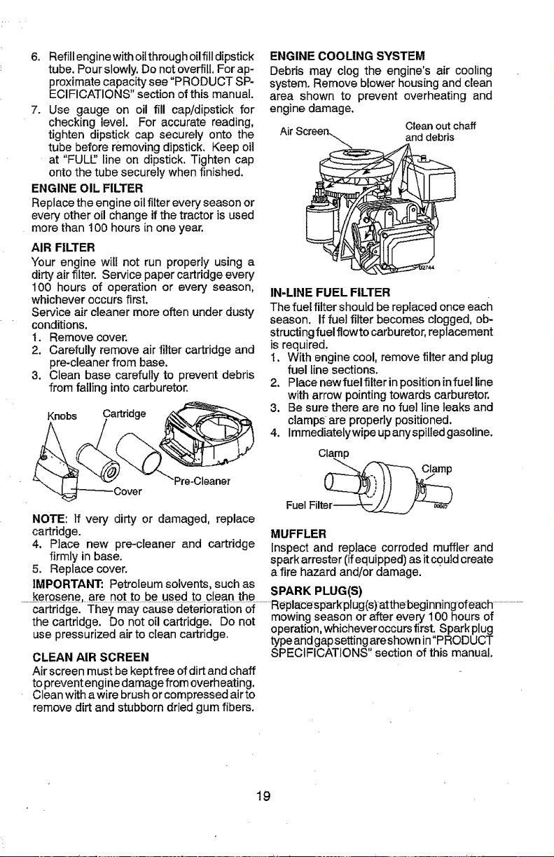
ENGINE COOLING SYSTEM
Debris may clog the engine's air cooling
system. Remove blower housing and clean
area shown to prevent overheating and
engine damage.
Air Scree Clean out chaff
n"-.. and debris
IN-LINE FUEL FILTER
The fuel filter should be replaced once each
season. If fuel filter becomes clogged, ob-
structing fuel flowto carburetor, replacement
is required,
t. With engine cool, remove filter and plug
fuel line sections.
2. Place newfuelfilter in position infuel line
with arrow pointing towards carburetor.
3. Be sure there are no fuel line leaks and
clamps are properly positioned.
4. immediatelywipeup anyspilled gasoline.
Clamp
'Pre-Oleaner
Fuel Filter-_-_--__../---_
NOTE: If very dirty or damaged, replace
cartridge.
4. Place new pre-cleaner and cartridge
firmly in base.
5. Replace cover.
MUFFLER
Inspect and replace corroded muffler and
spark arrester (if equipped) as it could create
afire hazard and/or damage.
IMPORTANT: Petroleumsolvents, such as
a i Replacesparkplag(s) atthebeg_nnlngoteacn
c rtr'dge_ They may cause deteriora{ion of
the cartridge. Do not oil cartridge, Do not
use pressurized air to clean cartridge.
CLEAN AIR SCREEN
mowing season or after every 100 hours of
operation, whichever occursfirst. Spark plug
type and gapsetting areshown in"PRODUCT
SPECIFICATIONS" section of this manual.
Air screen must be keptfree of dirt andchaff
toprevent enginedamage from overheating.
Clean with a wire brush or compressed airto
remove dirt and stubborn dried gum fibers.
19
Page 20
CLEANING
• Clean engine, battery, seat, finish, etc.
of all foreign matter.
• Clean debris from steering plate.
Debris can restrict clutch/brake pedal
shait movement, causing belt slip and
loss of drive.
& CAUTION: Avoid all pinch points and
movable parts
_ CclUtch!brakepedal_y
topside f _z_J
SteeneJi_ngaSdYStJomw'erDaS_h'shown_1_ Pinch
- Keep finished surfaces and wheels
free of all gasoline, oil, etc.
. Protect painted surfaces with automo-
tive type wax.
We do not recommend using a garden hose
or pressure washer to clean your tractor
unless the engine and transmission are
covered to keep water out. Water in engine
or transmission will shorten the useful life of
_our tractor. Use compressed air or a leaf
lower to remove grass, leaves and trash
from tractor and mower.
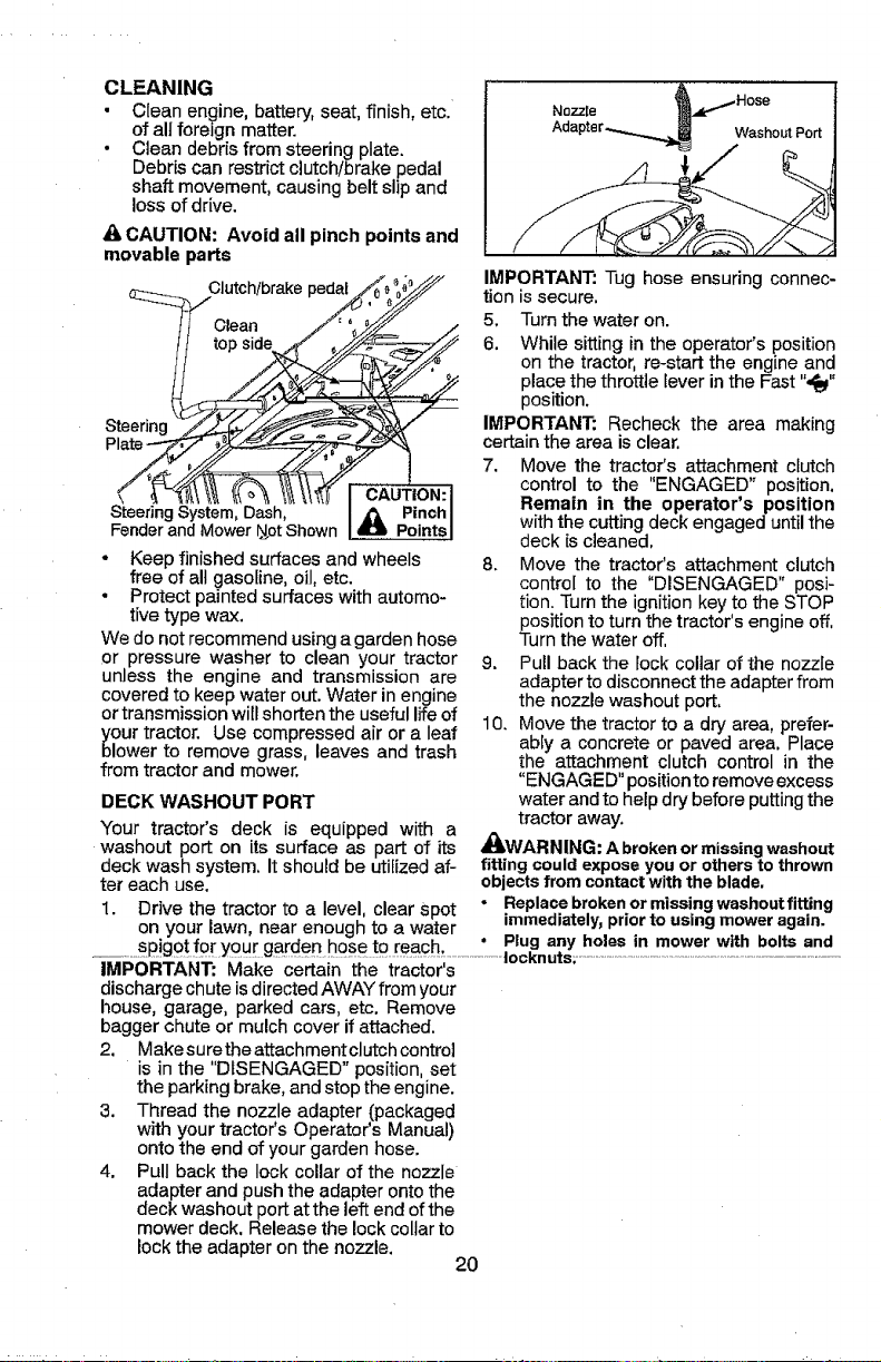
DECK WASHOUT PORT
Your tractor's deck is equipped with a
washout port on its surface as part of its
deck wash system, It should be utilized af-
ter each use,
1. Drive the tractor to a level, clear Spot
on your lawn, near enough to a water
Nozzle
Washout Port
IMPORTANT: Tug hose ensuring connec-
tion is secure.
5. Turn the water on.
6. While sitting in the operator's position
on the tractor, re-start the engine and
place the throttle lever in the Fast "_"
position.
IMPORTANT: Recheck the area making
certain the area is clear.
7. Move the tractor's attachment clutch
control to the "ENGAGED" position.
Remain in the operator's position
withthe cutting deck engaged untilthe
deck is cleaned.
8. Move the tractor's attachment clutch
control to the "DISENGAGED" posi-
tion. Turnthe ignition key to the STOP
position to turn the tractor's engineoff,
Turn the water off.
9. Pull back the lock coltar of the nozzle
adapter to disconnect the adapter from
the nozzle washout port,
10. Move the tractor to a dry area, prefer-
ably a concrete or paved area. Place
the attachment clutch control in the
"ENGAGED" position to remove excess
water andto help dry before putting the
tractor away.
_WARNING: A brokenormissing washout
fitting couldexposeyouor othersto thrown
objectsfromcontactwiththe blade,
• Replacebrokenormissingwashoutfltting
immediately_priortousingmoweragain.
IMPORTANT: Make certain the tractor's
discharge chute is directed AWAYfrom your
house, garage, parked cars, etc. Remove
bagger chute or mulch cover if attached.
2. Makesure the attachment clutch control
is in the "DISENGAGED" position, set
the parking brake, and stop the engine.
3. Thread the nozzle adapter (packaged
with your tractor's Operator's Manual)
onto the end of your garden hose.
4. Pull back the lock collar of the nozzle
adapter and push the adapter onto the
deck washout port at the leftend of the
mower deck, Release the lockcollar to
lock the adapter on the nozzle.
20
Page 21

I_WARNING: TO AVOID SERIOUS INJURY, BEFORE PERFORMING ANY
SERVICE OR ADJUSTMENTS:
1. Depress clutch/brake pedal fully and set parking brake.
2. Place motion control lever in neutral position.
3. Place attachment clutch in "DISENGAGED" position.
4. Turn ignition key to "STOP" and remove key.
5. Ensure the bIades and all moving parts have completely stopped.
6. Disconnect spark plug wire from spark plug and place wire where it cannot
come in contact with plug.
TO REMOVE MOWER
1. Place attachment clutch in "DISEN-
GAGED" position,
2. Lower attachment lift tever to its lowest
position.
3. Roll belt off engine pulley (M) and belt
keepers (G).
4. Remove retainer spring (K), slide collar
(L) off and push housing guide (P) out
of bracket.
5. Remove clutch cable spring (Q) from
idler arm (R).
6. Disconnect front link (E) from mower -
remove retainer spring and washer.
7. Go to either side of mower and discon-
nect mower suspension arm (A) from
chassis pin (B) and rear lift link (C) from
rear mower bracket (D)- remove retainer
springs and washers.
CAUTION: After rear liftlinks arediscon-
nected, the attachment liftleverwili bespring
toaded.Have a tight grip on liftlever when
changingposition of the lever.
8. Slide mower out fromunder right side of
tractor.
IMPORTANT: If an attachment other than
the mower is to be mounted on the tractor,
remove the front link (E) and rear lift links
(C) from tractor and hook the clutch spring
(Q) into the cable guide on front edge of
lower dash.
TO INSTALL MOWER
Ensuretractor isonlevel surface andengage
parking brake,
t. Lower attachment rift lever to its lowest
position.
_1_CAUTION: Lift lever is spring loaded.
Have a tight grip on lift lever, lower it slowly
and engage in lowest position.
NOTE: Ensure mower sidesuspension arms
(A)are pointing forward beforesliding mower
undertractor.
2. Slide mower under tractor until it is cen-
tered under tractor.
21
Page 22

3. ATTACH MOWER SIDE SUSPENSION
ARMS (A) TO CHASSIS - Position hole
in arm over pin (B) on outside of tractor
chassis and secure with retainer spring.
4. Repeat on opposite side of tractor.
7. Insert end of link (E) into hole in front
mower bracket (H) and secure with
washer and retainer spring (J).
5. ATTACH REAR LIFT LINKS (C) - Lift
rear corner of mower and position slot
in link assembly over pin (D) on rear
mower bracket and secure with washer
and retainer spring.
6. ATTACH FRONT LINK (E) - Work from
left side of tractor. Insert rod end of link
assembly through front hole in tractor
front suspension bracket (F).
8, Hook end of clutch cable spring (Q) into
hole in idler arm (R).
9, Push clutch cable housing guide (P) into
bracket, slide collar (L) onto guide and
secure with retainer spring (K),
10, Install belt onto engine pulley (M) and belt
keepers (G).
IMPORTANT: Check belt for proper routing
in all mower pulley grooves.
11.Raise attachment lift lever to highest
position,
12. Ifnecessary, adjust gauge wheels before
operating mower as shown in the O pera-
tion section of this manual.
22
03042rex
Page 23

TO LEVEL MOWER
Make sure tires are properly inflated to the
PSI shown ontires, lftires areover or under
inflated, it may affectthe appearance of your
lawn and lead you to think the mower isnot
adjusted properly.
VISUAL SIDE-TO-SIDE ADJUSTMENT
1. With alltires properlyinflatedand if your
lawn appears unevenly cut, determine
which side of mower is cutting lower.
2. With a3/4" or adjustable wrench, turn lift
link adjustment nut (A) to the leftto lower
LH side of mower, or, to the right to raise
LH side of mower.
NOTE: Each full turn of adjustment nut will
change mower height about 3/16".
FRONT-TO-BACK ADJUSTMENT
IMPORTANT: Deck must be level side-
to-side.
Toobtainthe best cutting results, the mower
blades should be adjusted so the front tip is
1/8" to !/2" lower than the rear tip when the
_ower is in its highest position.
CAUTION: Blades are sharp. Protect
your hands with gloves and/or wrap blade
with heavy cloth.
• Raise mower to highest position.
• Position any blade so the tip is pointing
straight forward, Measure distance (B)
to the ground at front and rear tip of the
blade.
• If fronttip of blade is not 1/8" to 1/2" lower
than the rear tip, go to the front of tractor,
• With an 11/18" or adjustable wrench,
loosen jam nut A several turns to clear
adjustment nut B.
Turn nut right Turn nut left
to raise mower \ to lower mower
3. Test your adjustment by mowing some
• With a 3/4" or adjustable wrench, turn
front link adjustment nut (B) clockwise
(tighten) to raise the front of mower, or,
counterclockwise (loosen) to lower the
front mower.
uncut grass and visually checking the
appearance, Readjust, ifnecessary, until
you are satisfied with the results,
PRECISION SIDE-TO-SIDE ADJUSTMENT
I. With alltires properly inflated,parktractor
on level ground or driveway.
_1=CAUTION: Blades are sharp, Protect
your hands with gloves and/or wrap blade
with heaW cloth.
....__._Ba!semowertQ its highest position .........'............................!_!_
3. At both sides of mower, position blade at Tightenadjustnut
side and measure the distance (A) from Bto raisemower
bottom edge of blade tothe ground. The
distance should be the same on both
sides.
4. If adjustment is necessary, see step 2 in
Visual Adjustment instructions above.
5. Recheck measurements, adjust ifneces-
sary untilboth sides are equal.
NOTE: Each full turn ofthe adjustment nut
will change mower height about 1/8".
- Recheck measurements, adjust if neces-
sary until front tip of blade is 1/8" to 1/2"
lower than the rear tip.
• Hold adjustment nut inpositionwithwrench
and tighten jam nut securely against ad-
justment nut.
23
nut Bto lower
mower
Loosen jam nut A first
Page 24

TO REPLACE MOWER BLADE DRIVE
BELT
The mower blade drive belt may bereplaced
without tools. Park the tractor on level sur-
face. Engage parking brake.
BELT REMOVAL -
1. Remove mowerfromtractor (See"TO RE-
MOVEMOWER"inthissectionofmanual).
2. Work belt off both mandrel pulleys and
idfer pulleys.
3. Pull belt away from mower.
BELT INSTALLATION -
1. Work belt around both mandrel puUeys
and idler pulleys
2. Ensure belt is in all pulley grooves and
inside all belt guides.
3, Install mower (See "To Install Mower" in
this section of this manual).
Mandrel Idler
Mandrel
BELT INSTALLATION -
1. Install new beltfrom tractor rearto front.
over the steering plate (F) and above
clutch brake pedal shaft (G).
2. Pull belt toward front of tractor and roll
belt onto engine pulley (E).
3. Pull belttoward rear of tractor, Carefully
work belt down around transmission
cooling fan and onto the input pulley (D).
Ensure belt is inside the belt keeper.
4. Install belt on centerspan idler (C).
5. Install belt through stationary idler (A)
and clutching idler (B).
6. Ensure belt is in all pulley grooves and
inside all belt guides and keepers,
7. Install mower (See "TO INSTALL MOW-
ER" inthis section of manual).
TO REPLACE MOTION DRIVE BELT
Park the tractor on level surface, Engage
parking brake. For assistance, there is a
belt installation guide decal on bottom side
of left footrest.
BELT REMOVAL-
1. Remove mower (See "TO REMOVE
TO CHECK BRAKE
If tractor requires more than five (5) feet to
stop at highest speed in highest gear on a
level, dry concrete or paved surface, then
brake must be serviced.
......... MOWER!! in this section of manual)...................You may-also check brake+by;......................................
NOTE: Observe entire motion drive belt
and position of all belt guides and keepers,
2, Remove belt from stationary idler (A)and
clutching idler (8).
3. Remove belt from centerspan idler (C).
6, Pull belt slack toward rear of tractor.
Carefully remove belt upwards from
transmission input pulley and over cool-
ing fan blades (D),
4. Remove belt downward from engine
pulley (E).
5. Slide belt toward rear of tractor, off the
1, Park tractor on a level, dry concrete or
paved surface, depress brake pedal all
the way down and engage parking brake.
2. Disengage transmission by placing
freewheel control in "transmission dis-
engaged" position, Pullfreewheel control
out and into the slot and release so it is
held in the disengaged position.
The rear wheels must lock and skid when
you tryto manually push the tractor forward.
If the rear wheels rotate, then the brake
needs to be serviced. Contact a Sears or
other qualified service center.
steering plate (F)and removefrom tractor.
24
Page 25

TO REMOVE WHEEL FOR REPAIRS
1. Block up axle securely,
2. Remove axle cover, retaining ring and
washers to allow wheel removal (rear
wheels have a square key- Do not lose).
3. Repair tire and reassemble.
NOTE: On rearwheels only: align grooves in
rear wheel hub and axle. Insert square key.
4. Replacewashers and snapretaining ring
securely in axle groove.
5. Replace axle cover.
NOTE: To seal tire punctures and prevent
flat tires due to slow leaks, purchase and
usetire sealant from Sears. Tire sealant also
prevents tire dry rot and corrosion,
Washers
Retaining
Axle
NOTE: If additional clearance is needed to
get to adjustment bolt, move mower =deck
height to the lowest position.
After above adjustment is made, ifthe trac-
tor still creeps forward or backward while
motion control lever is in neutral position,
follow these steps:
1. Loosen the adjustment bolt.
2. Movethe motion control lever 1/4 to 1/2
inch in the direction it is trying to creep.
3. Tighten adjustment bolt securely.
4. Start engine and test.
5/ Iftractor still creeps, repeat above steps
until satisfied.
TO START ENGINEwrrH WEAK BATTERY
_ILWARNING: Lead-acid batteries gener-
ate explosive gases. Keep sparks, flame
andsmoking materials away from batteries.
Always wear eye protection when around
batteries.
lfyourbattery istooweakto startthe engine, it
Square
(Rear Wheel Only)
FRONT WHEEL TOE-IN/CAMBER
Your new tractor front wheel toe-in and
camber is set at the factory and is normal.
The front wheel toe-in and camber are not
adjustable. If damage has occurred to
affect the factory set front wheel toe-in or
camber, contact a Sears or other qualified
service center.
TRANSAXLE MOTION CONTROL LEVER
NEUTRAL ADJUSTMENT
Themotioncontrol leverhasbeenpresetatthe
factory; adjustment should notbe necessary.
1. Loosen adjustment bolt in front of the
right rear wheel, and lightly tighten.
2. Start engine and move motion control
leveruntil tractor does not moveforward
or backward.
should berecharged, (See"BATI-ERY" inthe
MAINTENANCE section of this manual).
If "jumper cab[es" are used for emergency
starting, follow this procedure:
IMPORTANT: Yourtractor is equipped with
a12volt system. The othervehicle must also
be a 12 volt system. Do not use your tractor
battery to start other vehicles.
TO A-I-FACHJUMPER CABLES -
1. Connectone end ofthe RED cabletothe
POSITIVE (+)terminal of each battery(A-
B),taking care notto short againsttractor
chassis.
2. Connect one end of the BLACK cable
to the NEGATIVE (-)terminal (C) offully
charged battery.
3. Connect the other end of the BLACK
cable (D)to good chassis ground, away
from fuel tank and battery.
TO REMOVE CABLES, REVERSE ORDER-
=-3.-Hold motioncontrollever inthatposition__1 ._BLACK cablefirst from chassis andthen .........
and turn engine off. from the fully charged battery,
4. While holding motion control lever in 2. RED cable lastfrom both batteries.
place, loosen the adjustment bolt.
5. Move motion control lever to the neutral
(lock gate) position.
6, Tighten adjustment bolt securely. Weak or
Neutral Dead
Lever Lock Battery
Gate
Adjustment Bolt
25
Page 26

REPLACING BATTERY
n_asWARNING: Do not short battery termi-
byallowing a wren chorany other object
to contact both terminals at the same time.
Before connecting battery, remove metal
bracelets, wristwatch bands, rings, etc.
Positive terminal must be connected first to
prevent sparking from accidental grounding.
1. Lift seat pan to raised position.
2. Remove terminal cover.
3, Disconnect BLACK battery cable then
RED battery cable and carefully remove
battery from tractor.
4. Install new batterywith terminals insame
position as old battery.
5. Reinstall terminal cover.
6. First connect RED battery cable to posi-
tive (+) battery terminal with be_tand nut
as shown. Tighten securely.
7. ConnectBLACKgrounding cableto nega-
tive (-) battery termina] with remaining
bolt and nut. Tighten securely
8. Lower seat pan.
TO REPLACE FUSE
Replace with20amp automotive-type plug-
in fuse. The fuse holder is located behind
the dash.
TO REMOVE HOOD & GRILL ASSEMBLY
1. Raise hood.
2. Unsnap headlight wire connector.
3. Stand in front of tractor. Grasp hood at
sides, tilt toward engine and lift off of
tractor,
4. When replacing hood, Ensure to recon-
nect the headlight wire connector.
_g_t H°°d
rWire
Seat
Terminal
Cover\\ Nega_ve
Positive
(Red)
(Black)
Nut
Bolt
1. Raise hood.
2. Remove bulb holder from the hole inthe
backside of the grill.
3. Replace bulb in holder and install bulb
holder securely back into the hole in the
backside of the grill.
4. Close hood.
INTERLOCKS AND RELAYS
Loose or damaged wiringmay cause your
tractortorun poorly, stop running, orprevent
itfrom starting.
• Check wiring.
TRANSMISSION REMOVAL/REPLACE-
MENT
Should yourtransmission require removalfor
service or replacement, it should be purged
after reinsta]lation and before operating the
tractor. See "PURGE TRANSMISSION" in
the Operation section of this manual.
ENGINE
TO ADJUST THROTrLE CONTROL
The throttle control has been preset at
the factory and adjustment should not be
necessary Check adjustment as described
below before loosening cable, If adjustment
is necessary, see engine manual.
factory andadjustment should not beneces-
sary. If adjustment is necessary, see engine
manual
TO ADJUST CARBURETOR
Yourcarburetor hasbeenpreset atthe factory
and adjustment should not be necessary.
However, minor adjustment may berequired
to compensate for differences in fuel, tem-
perature, altitude or load. Ifthe engine does
need adjustment, see engine manual,
26
Page 27

Immediately prepare your tractor for storage
at the end ofthe season or if the tractor will
not be used for 30 days or more.
_,WARNtNG: Never store the tractor with
gasoline inthe tank inside a building where
fumes may reach an open flame or spark.
Allow the engine to cool before storing in
any enclosure.
TRACTOR
Remove mower from tractor for winter
storage. When mower is to be stored for a
period of time, clean it thoroughly, remove
all dirt, grease, leaves, etc. Store in a clean,
dry area.
1. Clean entire tractor (See "CLEANING"
in the Maintenance section of this
manual),
2. Inspect and replace belts, if necessary
(See belt replacement instructions inthe
Service and Adjustments section of this
manual).
3. Lubricate as shown in the Maintenance
section of this manual,
4, Ensure that all nuts, bolts and screws
are securely fastened. Inspect moving
parts for damage, breakage and wear.
Replace if necessary,
5. Touch up all rusted or chipped paint
surfaces; sand lightly before painting.
BATTERY
- Fully charge the battery for storage,
• After a period of time in storage, battery
may require recharging.
• To help prevent corrosion and power leak-
age during long periods ofstorage, battery
cables should be disconnected and bat-
tery cleaned thoroughly (see "TO CLEAN
ENGINE
FUEL SYSTEM
IMPORTANT: It is important to prevent
gum deposits from forming in essential fuel
system parts such as carburetor, fuel hose,
ortank duringstorage.Also, alcohol blended
fuels (called gasohol or using ethanol or
methanol) can attract moisture which leads
to separation and formation of acids during
storage. Acidic gas can damage the fuel
system of an engine while instorage,
. Empty the fue! tank by starting the engine
and letting it run until the fuel lines and
carburetor are empty.
• Never use engine or carburetor cleaner
products in the fue! tank or permanent
damage may occur.
° Use fresh fuel next season.
NOTE: Fuel stabilizer is an acceptable al-
ternative in minimizing the formation of fuel
gumdeposits during storage. Add stabilizer
to gasoline infuel tank or storage container.
Always followthe mixratiofound on stabilizer
container. Run engine at least 10 minutes
afteradding stabilizer toallowthe stabilizerto
reach the carburetor. Do not empty the gas
tank and carburetor ff using fuel stabilizer.
ENGINE OIL
Drain oil (with engine warm) and replace
with clean engine oil. (See "ENGINE" inthe
Maintenar_cesection of this manual).
CYLINDER(S)
1. Remove spark plug(s).
2. Pourone ounce ofoilthrough spark plug
hole(s) into cylinder(s).
3. Turn ignition key to "START" position for
afew seconds to distribute oil.
4. Replace with new spark plug(s).
. Aftercleaning, leave cables disconnected
andplace cables where they cannot come
in contact with battery terminals.
• If battery is removed from tractor for
storage, do not store battery directly on
concrete or damp surfaces.
• Do not store gasoline from one season to
another.
• Replace your gasolinecan ifyour canstarts
to rust. Rust and/or dirt in your gasoline
will cause problems,
• If possible, store your tractor indoorsand
cover ittogive protection from dustand dirt.
• Cover your tractor with a suitable protec-
tive cover that does not retain moisture.
Do not useplastic. Plasticcannot breathe
which allows condensationto form and will
cause your tractor to rust.
IMPORTANT: Never cover tractor while
engine and exhaust areas are still warm.
27
Page 28

TROUBLESHOOTING CHART:
See appropriate section in manual unless directed to Sears service center
PROBLEM CAUSE CORRECTION
Will not start 1 Out Offuel: i Fill fuel tank.
Hard to start 1 Dirty air filter, 1 C]ean/replace air filter.
! Engine will not 1 Clutch/brake pedal no_depressed. 1 Depress ClLrtch]brake pedal
_turn over
,, ...................... u,,,.........
2 Engine net"CHOKED" properly. [ 2 See "TO START ENGINE" in
3 Engine flooded. 3 1Wait several m nutes before
4 Bad spark plug. 4 Replace spark plug.
5 Dirty air filter. 5 Clean!replace air filter.
6 Di_j fuel filter. 6 Replace fuel filter.
7 Water in fuel. 7 ! Empty fuel tank and carburetor.
8 Loose or damaged wiring. 8 Check all wiring.
9 Carburetor out of adjustment. 9 See "To Adjust Carburetor" in
1Q Engine valves out of adjustment. 10 Contac_ a Sears or other qualified
2. Bad spark plug, 2 Replace spark plug.
3 Weak or dead battery. 3 Recharge or replace battery.
4 Dirty fuel filter. 4 1Replace fuel filfe_.
5 Sta_e or dirty fuel. 5 Empty fuel _ank and refilI lank wi_
6 Loose or damaged wiring. 6 Check all wiring.
7 Carburetor out of adjustment. 7 See "To Adjust Carburetor" in
8 Engine valves out of adjustment. 8 ! Contact a Sears or other qualified
2 Attachment clutch is engaged. 2 Disengage attachment clutch.
3 Weak or dead battery. 3 . Recha_e oJ [ep ace batte_. .............
4 Blown fuse. 4
5 Corroded battery terminals. 5
6 Loose or damaged wiring. 6
7 Faulty ignition switch. 7
8 Faulty solenoid or starter. 8
9 Faulty operator presence 9
switch(es).
Operation section.
attempting to start.
refill tank with fresh gasoline and
repIace fuel filter.
Service and Adjustments section.
service center.
fresh, clean gasoline.
Service and Adjustments section.
service center.
Replace fuse.
Clean battery terminals.
Check _11wiring.
Check/replace ignition switch.
Check/replace solenoid or starter.
Con!act a Sears or other qualified
service center.
28
Page 29

TROUBLESHOOTING CHART:
See appropriate section in manual unless directed to Sears service center
PROBLEM ..............
Engine clicks but
will not start
Loss of power
Excessive vibration
............................................................................................................................................................................Replace damagedparts,. .....................................
L
Engine continues to 1 Faulty operator-safety presence 1 Check wiring, switches and
run when operator control system, connections. If not corrected,
leaves seat with atta- contact a Sears or other
ichment clutch engaged
....,,,,,,_
CAUSe ....
1, "Weak or dead battery,
2 Corroded battery terminals.
3 Loose or damaged wiring,
4 Faulty solenoid or starter.
1 Cutting too much grass/too fast.
2 Throttle in "CHOKE" position,
3 Build-up of grass, leaves and
trash under mower.
4 Dirty air filter.
5 Low oil level/dirty oil.
6 Faulty spark plug.
7 Dirty fuel filter.
8 Stale or dirty fuel.
9 Water in fuel.
1o
Spark plug wire bose,
11
birty engine air screen/fins:
i12
Dirty!clogged muffler,
13
Loose or damaged wiring.
14
Carburetor out of adjustment,
15
Engine valves out of adjustment,
1
Worn, bent or loose blade.
2
Bent btade mandrel,
,3 , Loose/damaged part(s), ,3 Tighten loose part(s).
iii
CO..ECTIO"
1 Recharge or replace battery.
2 Clean battery terminals.
3 Check all wiring.
4 Check/replace solenoid or starter.
1 Raise cutting height/reduce speed
2 Adjust throttle control.
3 Clean underside of mower
housing.
4 Clean/rep_ace air filter.
5 Check oil level/change oil.
6 Clean®aporchange sparkpiug
7 Replace fuel filter.
8 Empty fuel tank and refill tank witf
fresh, clean gasoline,
9 Empty fuel tank and carburetor,
refill tank with fresh gasoline and
replace fuel filter.
10 Connect & tighten spark plug wire
11 Clean engine air screen/fins.
12 Clean/replace muff/or.
13 Check all wiring.
14 See "To Ad ust Carburetor*' in
8erv ce and Adjustments section.
15 Contact a Sears or other qualified
service center,
1 Replace blade, Tighten blade bolt
2 Contact a Sears or other qualified
service center,
29
Page 30

TROUBLESHOOTING CHART:
See appropriate section in manual unless directed to Sears service center
PROBLEM
Poor cut - uneven
cutting
Mower blades will
not rotate
,,j
Poor grass
discharge
Headlight(e) not 1 Light switch is "OFF", 1 Turn light swizch "ON".
working
(if so equipped) 2 Bulb(s) or lamp(s) burned out. 2 Replace bulb(s) or lamp(s).
CAUSE
1
Worn. bent or loose blade, 1
2
Mower deck not level. 2
3
Buildup of grass, leaves, and 3
trash under mower.
4
Bent blade mandrel, 4
5
Clogged mower deck vent from 5
build-up of grass, leaves, and
trash around mandrels.
1
Obstruction in clutch mechanism. 1
2
Worn/damaged mower drive be{t 2
3
Frozen idler pulley. 3
4
Frozen blade mandrel, 4
l
Engine speed too slow.
2
Travel speed too fast.
3
Wet grass.
4
Mower deck not level.
5
Low/uneven tire air pressure.
6
Worn, bent or loose blade.
Buildup of grass, leaves and
trash under mower.
8
Mower drive belt worn.
9
Blades improperly installed.
10
Improper blades used,
11 Clogged mower deck vent holes 11 Clean around mandreis to
from buildup of grass, leaves, and open vent holes.
trash around mandrels.
J3 Faulty light switch, 3 Check/replace light switch.
4 Loose or damaged wiring. 4 Check wiring and connections,
5 Blown fuse, 5 Replace fuse.
,,,,,
CORRECTION
Replace blade, Tighten blade bolt
Level mower deck,
Clean underside of mower
housing.
Contact a Sears or other
qualified service center,
Clean around mandrels to
open vent holes,
Remove obstruction.
Replace mower drive belt,
Replace idler pulley.
Contact a Sears or other
qualified service center.
Place throttle control in "FAST"
position.
2
Shift to slowerspeed.
3
Allow grass to dry before mowing
4
Level mower deck.
5
Check tires for proper PSI.
6
Replace/sharpen blade. Tighten
blade bolt,
Clean underside of mower
housing.
8
I Replace mower drive belt.
9
Reinstall blades sharp edge down,
10
Replace with blades listed in
this manual,
, ,,,,,_,
3O
Page 31

TROUBLESHOOTING CHART:
See appropriate section in manual unless directed to Sears service center
P.OB E.
Battery will not
charge
,,,
Loss of drive
,,,,,
Engine "backfires" 1
when turning
engine "OFF"
Engine dies when 1
tractor is sni_ea
into reverse
CAUSE
1
Bad battery ceil(s). 1
2
Poor cable connections 2
3
Faulty regulator (if so equipped). 3
4
Faulty alternator, 4
1
i Freewheel control in 1
"DISENGAGED" position,
2
Debris on steering plate (if 2
equipped).
3
Motion drive belt worn, damaged, 3
or broken.
4
A_rtrapped in transmission during 4
shipment or servicing.
Axle key missing. 5
Engine throttle control not se' 1
between half and full speed (fast
position before stopping engine,i
,,,,,,,
Reverse operation system (ROS) 1
is not "ON" while mower or other
attachment isengaged.
CORRECTION
Replace battery,
Check/'ctean all connections.
i Replace regulator,
Replace alternator,
Place freewheel control in
"ENGAGED" position.
See "CLEANING '=in the
maintenance section,
Replace motion drive belt,
Purge transmission,
Install axle key at rear wheel See
"TO REMOVE WHEEL" in the
Service and Adjustments section,
,, ,,,, ,,
Move throttle control between
half and full speed (!ast) position
before stopping engine.
Turn ignition key to ROS "ON"
position, See Operation section.
i NEED MORE HELP?
i Youql find the answer and more on managemyhome.cora - for free!
i . Find this and a[{ your other product manuals online. .
i " Get answers from our team of home experts,
,-i--...Get-a. personaLized- maintenance p[an. for_your-home_ ..........................................................................................................................
- Find information and tools to he[p with home projects.
manage home
brought to yo_ by Sears _i
31
Page 32

P,3
SUGGESTED GUIDE FOR SIGHTING SLOPES FOR SAFE OPERATION
ONLY RIDE UP AND DOWN HILL,
NOT ACROSS HILL
15 DEGREES MAX,
down the face of slopes, never across the face. Do not mow
WARNING: To avoid serious injury, operate your tractor up and
slopes greater than 15 degrees. Make turns gradually to prevent
tipping or loss of control, Exercise extreme caution when
changing direction on slopes.
t. Fold this page along dotted line indicated above.
2. Hold page before you so that its left edge is vertically parallel to a tree
trunk or other upright structure.
3. Sight across the fold in the direction of hill slope you want to measure.
4. Compare the angte of the fold with the slope of the hill,
Page 33

Garant_a.......................................................... 33
Reglas de Seguridad ...................................... 34
Espeeificaciones del Producto ........................ 37
Montaje/Pre Operaci6n ................................... 38
Operaci6n ....................................................... 40
Programs de Mantenimiento .......................... 47
Servic]o y Ajustes ........................................... 52
Almacenamiento ............................................. 58
Identificaci6n de Problemas ........................... 59
Servicio Sears ............................. Contraportada
Mantenimiento ................................................ 47
Garantia pare equipos tractores Craftsman
GARANTiA COMPLETA DE CRAFTSMAN
PeR DOS ANOS desde la fecha de compra, todas las partes no sustituibies de este equipo tractor est_.n
garantizadas centre cualquier defects de material o mane de obra, Una parle no auetituib]e defectuosa
recibir_, reparaciSn o reemplazo gratuito encasa si la reparaci6n es imposible.
PeR CINOO AktO$ desde la fecha de compra, el bastidor y el eje delantero de este equipo tractor est_n
garantizados centre cualquisr defecto de material o mane de obra, Un bastidor o eje cletantero defectuoso
recibir& reparaci6n o reemplazo gratuito encasa si la reparaci6n es imposible.
DURANTE 90 D[AS deede la fecha de cempra, la bateda (una parts eustltuible) de este equipo tractor
est_ garantizada centre cualquier defecto de material o mane de obra (nuestra prueba comprueba qua no
sontendr_ carga). Una bater[a defectuesa recibir& un reemplazo gratuito en easa,
GARANTiA LtMITADA DE PeR VIDA ADICiONAL en el EJE DELANTERO DE HIERRO COLADO (si
est_ provisto)
DURANTE EL TIEMPO EN QUE SE USE per et propietario original despu_s del quinto erie a partir de la
fecha ds compra, el eje delantero de hierro colado (si est_ provisto) de este equipo tractos estd garantizado
centre cualquier defecto de material o mane de obra, Con el comprobante de eompra, un eje delanterO de
hierro colado recibird un reemplazo gratuito en ease,
SERV|CIO DE GARANTiA
Pare conocer los detalles de Ia cobertura de garantia para obtener una reparaci6n o reemplazo gratuito,
!lame al 1-800-6_19-5917 6 visits el sit{o web: www, craflsman.com
En redes los cases anteriores, si el reemp]azo es imposible, el equipo tractor ser_ sustituido sin cargo con
et mismo modelo o uno equivalents.
Toda la cobertura do garantia anterior ser_ nuts sieste equipo tractor se utWza alguna vez para brindar
servicios comerciales osi se alquila aotra persona.
Esta garantia cubre 0NICAMENTIE defectos do material y mane de obra. La cobertura de garantia NO incluye;
• Parles sustituibles (excepto la bataria) que se puedan desgastar per eI use normal dentro de1 periodo de
garantia incluso, pare sin limitarse a, cuchillas, bujias, fittros de airs, correas y filtros de aceite.
• Servicios de mantenimiento est_ndar, eatables de aceite o afinaciones.
• Reemplazo o reparaciSn de neum_tices per pinchazoa causeries per objetos externos come clavos,
espinas, tecones o vidrios.
-:--Reem-pla'7o o reparaci6ri cle neum&tiCOs o rueda_ per desgaste normal; accidentes o per operaci6n o ...........
mantenimiento incorrectos.
• Reparaciones necesarias per abuse del operador inclueo, pare sin limitarse a, dares causeries per
remolcar objetos que superen la capacidad clef equipo tractor, chocar contra objetos qua doblen el
bastidor, el ensambEe de] eje o el cigQefial o sobrepasar la velocidad del motor,
• IRe_araci_nesnecesariasp_rnegl{genciade_o_erad_r'inc_us_(_er_sin_imitarseae_[_)da_se_ctric_s
y mec&nicos causeries per el almacenamiento incorrecto, per no user el grade y la cantidad correctos de
aceite de motor, per no mantener del muetle libra de residues inflamables o per no mantener el equipo
tractor de acuerdo con Ias instrucciones qua contiene el manual del operador.
• Limpieza o reparaciones deI motor (sistema de combustible) cuando se determine qua se us6
combustible contaminado y oxidado (sarro). En general, el combustible debe usarse dentro de los 30
dias posteriores a su compra.
• Deterioro y desgaste normal de los acabaclos exteriores o sustituciSn de r6tulos de productos.
Esta garantia le otorga derechos legales especfficos, y usted tambi(_n puede tenet otros derechos qua
varian ds un estado a otro,
Sears Brands Management Corporation, Hoffman Estates, IL 60179
33
Page 34

_PELtGRO: Esta Maquina cortadora es capaz de amputar las manosy los pies y de lanzar
objetos, si no se observan las |nstrucciones de seguridad siguientes se pueden producir
lesiones graves o [a muerte,
_DVERTENCIA: Siempre desconecte el alam-
bre de la bujta y p6ngaloderide no pueda entrar
en contact<) con la bujia, para evitar el arranque
per accidente, durante la preparaci6n, el trans-
porte, el ajuste ocuando se hacen reparaciones,
_ADVERTENClA: Noavarice cuesta abajoa pun-
to rnuerto yaque podria perderel control del tractor,
_&.DVERTENCIA: Remolque solamente los
accesorios recomendados y conforrnes alas
caracteristicas indicadas per el fabricante de su
tractor. Tenga cuidado y prudencia al utilizar el
tractor. Cuando se encuentre en un dec]lye, oper
utilizando exclusivarnente la velocidad rn&sbaja,
En case de un declive una carga excesiva po-
drla resultar peligrosa. Los neurn&ticos pueden
pettier la tracc]6n con el sue]o y hacerle perder
el control de su tractor.
_ADVERTENCIA: E[tubo de escape del motor,
algunos de sus constituyentes y algunos corn-
ponentes del vehicu!o contienen o desprenden
productos quirnicos conocidos en el Estado de
California come causa de c&ncer y defectos al
nacimiento u otros daSos reproductivos.
_II_ADVERTENCIA: Los bornes, terrnina]es y ac-
cesorios relatives de la baterfa contienen plorno
o cornpuestos de plomo, productos qu_micos
conocidos en el Estado de California come causa
de c&ncer y defectos al nac]rniento u otrosdaSos
reproductivos. Lavar las manes despu_s de
manipularlos.
I. FUNCIONAMIENTO GENERAL
• Leer,entender y seguirtodas ]as instruco]ones
sobre la rn&quina yen el manual antes de
ernpezar.
° No poner las manes o los pies cerca de partes
giratoriaso debajo de la rn&quina, rnantener
s]empre Iimpia la abertura de descarga.
• Permitir eI funcionarniento de ta m&quina s61o
--a adultos que tengan farnitiaridad con las ..............dura_de aceite o carburante antesde hacer-
instrucciones,
• Lirnpiar el area de objetos come piedras,
juguetes, cables, etc. que pueden ser recogi:
dos y disparados con las cuchillas.
• Asegurarse de que el drea est_ librede otras
personas antes de ponerla en rnarcha. Parar
Ia m&quina si alguien entra en el _rea.
• Nunca llevar pasaieros,
° No cortar marcha atr&s al no ser absolu-
tamente necesario. Mirar siempre abajo y
delante mientras se precede atr&s.
• Nunca dirigir el material descargado hacia na-
die. Evitar descargar material contra paredes
u obstrucciones. El material podria rebotar
hacia el operador. Parar las cuchillas cuando
se pasan superficies de grava.
• No maneje la rn_.quina si no tiene _atrarnpa
para c6sped cornpleta, Ia canaleta de descarga
u otros dispositivos de seguridad en su lugar
yen funcionamiento.
• Ralentizar antes de g]rar,
• Nunca dejar una m&quina encendida sin vigi-
lancia. Apagar siernpre Ias cuchillas, poner el
freno de estacionamiento, parar el motor, y
quitar las ]laves antes de bajar.
• Desenganche ]as hojascuando no est6 cortan-
do c6sped. Apague elmotor y espere hasta que
todas las partes se detengan percomplete an-
tes de lirnpiar la m&quina, retirar latrampa para
c6sped o destapar la canaleta de descarga.
• Hacer funcionar la rn&quina s61ocon la luz del
dia o luz artificial buena.
• No hacer funcionar la rn&quJna estando bajo
los efectos de alcohol o droga.
• Poner atenci6n al tr&fico cuando se opera
cerca de calles o se cruzan.
°Poner ta rn&v,ima atenci6n al cargar o descar-
gar Ia rn&quina en una caravana o cami6n.
° Uevar siempre galas de protecci6ncuando se
bace funcionar la rn_,quina,
• Los dates indicanque los operadoras a partir
de los 60 aries est_n afectados per un gran
porcentaje deheridas relativas ala conducci6n
del cortac@sped, Estos operadores tendrian
que evaluar su habilidad de hacer funcionar
el cortac6sped de mode Io bastante seguro
para proteger a sJ mismos y a otras personas
de heridas graves.
• Seguir las recornendaciones del fabricante
para los pesos y contrapesos de Ias ruedas,
• Mantener la rn&quina libre de hierba, hojas u
otros escornbros que pueden tocar eEtube de
escape/partes deImotor calientes y quemarse.
No permitir que el puente de1 cortac6sped
cargue hojas u otros residues que pueden
causar acumulaciones. Limpiar toda salpica-
operaciones sobre Ia rn&qu]na o guardarla.
Dejarla enfriar antes de guardarla,
II. FUNCIONAMIENTO EN PENDIENTES
Las pendientes son el mayor factor de accidentes
relatives a Ia perdida de control y vuelco, que
pueden causar severas heridas o muerte. El fun-
cionarniento en pendientes requiere una atenci6n
extra, Si no es posible hacer marcha atr_.senuna
pendiente o si te sientes incornodo,no la cortes.
• Cortar hacia arriba y abajo de una pendiente,
no de mode horizontal.
° Poner atenciones a los hoyos, Ias raices, los
bultos, ]as piedras u otrosobjetos escondidos.
El terreno irregular puede volcar la mbquina,
La hierba alta puedeesconder obst&culos.
34
Page 35

- Escoger una velocidad de marcha baja de
modo que no sea necesano pararse o cambiar
estando en una pendiente.
• No cortar la hierba mojada. Los ruedas pueden
perder tracci6n.
Porter slempre una marcha cuando se est&
en pendientes. No porter en punto muerto e ir
ouesta abajo.
° Evitar arrancar, pararse ogirar en una pendieno
to. Si Ias ruedas pierden tracci&n, desconectar
los cuchillas y proceder despacio cuesta abajo
en la pendiente,
° Mantener todo los movimientos en los pen-
dientes lentos y gradual No hacer cambios
repentinos de velocidad o direcci6n, ya que
pueden causer el escape de la m&quina.
• Poner la m&xima atenci6n cuando Ia mztquina
funciona con captadores de hierba u otros
disposit{vos enganchados; pueden afectar la
estabilidad de la m&quina. No user en pendi-
entes empinados.
• No intentar estabi{izar la m_,quinaponiendo el
pie en el terreno.
• No cortar cerca de bajadas, cunetas y orillas.
Losm_quina puede volcarse improv{samente
si una rueda est,, en el borde o se hunde.
IlL Nil;lOS
•(_ADVERTENCIA: LOS NIhIOS PUEDEN
SUFRIR DANOS CON EL USO DE ESTE EQUI-
PO. La Academia Estadounidense de Pediatria
(American Academy of Pediatrics) recomienda
que s61ose permita a niSos con una edad mini-
ma de 12 aSos mane{or m&quinas cortac_sped
manuales, y at menos de 16 aSos pare manejar
tractores cortac_sped.
Si el operador no pone atencibn a Ia presencia
de los nir_os pueden ocurriraccidentes tr&gicos.
Los niSos a menudo est_n atraidos por {am&qui-
nay los actividad de cotter. No dar pot hecho
de que los niSos se queden adonde estaban la
dltima vez que los vistes.
- Mantener os nifios fuera del _.rea de corte y recubiertos con un forro de pi_stico. Colocar
....._igil_d0s porun adulto resp_nsableque nosea .............siempre tosconten,edores:en et terreno ]ejos_
el operador, eel vemculo cuanao se esta ,enanao.
• Ester aterta y apagar la m&quina si un nifios
entre en et &tea.
• Antesydurantelamarchaatr_-,s, miraradetante
y abajo pare ver si hay nifos pequeSos.
• Nunca Ilevar nifios, incluso si hay las cuchillas
apagadas. Podr{an caer y hedrse sedamente
o interferir con el fiJncionamiento seguro de la
m&quina, los niSos que se hart [levado prec_
edenternente pueden aparecer de pronto en eI
_rea de corte por otto paseo y ser atropellados
o tumbados pot la m&quina.
• Nunca dejar que los ni_os manipulen Ia md-
quina.
• Toner el m&ximo cuidado cuando se acerca
a cantos ciegos, arbustos, &rboles u otros
objetos que pueden impedir Ia vista de niSos,
IV. REMOLQUE
• Remolcar sSIocon una m&quina que tonga un
gancho diseSado pare remolcar. Enganchar el
equipo o remolcar sSIo en el punto dispuesto
al efecto.
• Seguir las recomendaciones dotproductorcon
respecto a los limites deI equipo por remolcar
y el remolque en pendientes.
- Nunca permitir que niSos u otras personas
est_=ndentro del equipo pot remolcar.
• En pendientes, el peso del equipo remolcado
puede causar la p_rdJda de tracci6n y la p@r-
dido de control.
• Viajar despacio y dejar m&s distancia pare
frenar.
V. SERVICiO
MANIPULAC16N SEGURA DE LA GASOLtNA
Pare evitar heridas personales o da_os alas
eosas, poner el m_v,imo cuidado ala hora de
manipular la gasoline. La gasoline es extrema-
mente inflamable y los vapores son explosivos.
• Apagar todos los cigarrilIos, cigarros, pipes y
otras fuentes de ign{ciSn.
• Users61ocontenedores para gasolina aproba-
dos.
- Nunca quitar el tap6n de la gasoline o afiadir
carburante con el motor en marcha, dejar
enfriar el motor antes del abastecimiento de
la gasolina.
• Nunca abastecer Ia m_.quina al interiorde un
local
• Nunca guardar la m,_quina o el contenedor
del carburante donde haya una llama abierta,
chispas o una luz pilotocomo un calentador
de ague u otrosdispositivos.
• Nunca IIenar los contenedores al interior de
un vehicu]o o en una caravana o cami6n
• Quitar el equipo de gas del camiSn o caravana
y abastecerlo en el terreno. Si no es posible,
abastecer dicho equipo con un oontenedor por-
t,tit, m&s bien que de un surtidor de gasolina.
• Mantener la boquilla a contacto del borde
del dep6sito de carburante o la abertura del
contenedor durante toda la operaci6n de
abastecimiento. No utilizar un dispositivo con
boquitla cerrada-abierta.
• Si se vierte carburante sobre la ropa, cambi-
arse la rope inmediatamente.
• Nunca Ilenar eI depbsito m_s de Io debido.
Volver a colocar el tapbn deI gas y cerrar de
modo firme.
35
Page 36

OPERACIONES DE SERVICIO GENERALES
• Nunca hacer funcionar la m&quina en un,'_rea
cerrada.
• Mantener todas ]astuercas y pemos apretados
para asegurarse de que trabaja en condiciones
seguras.
• Nunca modificar los dispositivos de seguddad.
Controlar su correcto funcionamiento regular-
mente.
° Mantener ta m_quina Iibre de hierba, hojas
u otros residuos acumulados. Lirnpiar las
salpicaduras de aceite o carburante y quitar
cualquier cosa mojada con carburante. Dejar
que la m&quina se enfr_eantes de guardarla.
• Si se golpea un objeto ajeno, hay que pararse
e inspeccionar la m_.quina. Reparar, si es
necesario, antes de volver a poner en marcha.
• Nunca hacer ningfin ajuste o reparaci6n con
el motor en funci6n.
• Verifique los componentes de ]a tTampa para
c_spedy la canaleta dedescarga con frecuen-
ciay sustituya con repuestos recomendados
por elfabricante cuando sea necesado,
• Las cuchiUas del cortac(_sped son afiladas.
Envolver la cuchilta, ponerse guantes y porter
_am_ima atenci6n cuando se hacen opera-
ciones en ellas.
• Controlar el funcionamiento del freno frecuent-
emente, Ajustar y hacer las operaciones de
mantenimiento cuando eso sea necesario.
• Mantener y sustituir 1asetiquetas de seguridad
e instrucci6n, cuando sea necesario.
• Asegurarse de que el &rea est6 tibre de otras
personasantes de ponerlaen marcha, para la
m&quina si alguien entra en el _rea.
• Nunca Ilevar pasajeros,
• Nocortar marcha atr&s al no ser absolutamente
necesario, Mirar siempre abajo y delante
mientras se procede atr&s.
• Nunca Ilevar nifios, inclusosi hay Iascuchillas
apagadas. Podrian caer y herirse seriamente
o interferir con el funcionamiento seguro de la
m&quina, los nitros que se han Ilevado prec-
edentemente pueden aparecer de pronto en et
&reade corte por otto pa_eo y seratropellados
otumbados por la mfiquina.
•_M_,n:ter_er=!9_3|fi=osfuer=,_d_[_reade=_Qrtey ..........-_Alcargaro descarga_ia mz_quina,no sobrepase_
vigilados por un adulto responsab]e que no sea el &ngulo m_imo recomendado de 15°,
el operador.
- Estar alerta y apagar la m&quina si un nifios
entra en el &tea.
• Antes y durante Ia marcha atr&s, miraradelante
y abajo para ver si hay nifios pequefios.
• Cortar hacia arriba y abajo de una pendiente
(15° Mbx), no de modo horizontal.
• Escoger una velocidad de marcha baja de
modo que no sea necesario pararse o cambiar
estando en una pendiente.
• Evitar arrancar, pararseo giraren una pendien-
te. Si las ruedas pierden tracci6n, desconectar
las cuchillas y proceder despacio cuesta abajo
en Ia pendiente.
• Si la m&quina se para mientras va cuesta
arriba, desconectar las cuchillas, poner la
marcha atrfis y ir hacia atr&s despacio.
• No girar estando en pendientes si no es nece-
sario, y luego girar despacio y gradualmente
cuesta abajo, si es posible.
36
Page 37

ESPECIFICACIONES DEL PRODUCTO
Capacidad y Tipo 2.5 Galones/9.46 L
de Gasolina: Regular Sin Plomo
Tipo de Aceite SAE 30 (sobre 32°Fi0°G)
(API: SG-SL): SAESW30 (deabajo 32°F,/0°C)
Capacidad de Con Filtro: 56 Ozj'1,65 L
Aceite: Sin Filtro: 48 OzJ1,4 L
Bujia 0hampion ROt2YC
Sistema de 3 Arnps Bateria
Carga: 5 Amps Luces
Bateda: AmpiHr: 28
Torsi6n del Perno 45-55 Ft. Lbs.i62-75 Nm
de Ia Cuchilla:
FELICITACIONES por la compra de su tractor. Ha
sidodisefado> planiticado y fabricado para darle ia
mejor confiabilidad yel major rendimiento posible.
En et caso de qua se encuentre con cualquier
problema qua no pueda solucionar f,_cilmente,
haga el favor de ponerse en contacto con un
centro de servicio Sears o con un otro centro de
servicio cualificado. Cuenta con representantes
bien capacitados y competentes y con las her-
ramientas adecuadas para darle servicio o para
reparar este tractor.
Haga el favor de leer y de guardar este manual.
Estas instruc-ciones le permitir&n montar y man-
tener su unidad en forma adecuada. Siempre
observe las "REGLAS DE SEGURtDAD."
RESPONSABILIDADES DEL CLIENTE
• Lea y observe las reglas de seguridad.
• Siga un programa regular de mantenimiento,
cuidado y uso de su tractor.
• Siga las instrucciones descritas en las sec-
clones "Mantenimiento" y 'Almacenamiento"
de este manual.
• Utilice prendas de seguridad adecuadas al
rnanejar la m&quina, incluidos (como minimo)
calzado deseguridad, gafas protectoras y pro-
tecci6n auditiva. No utilice pantalones cortos
y/o calzado abierto cuando corte la hierba.
(Abertura: ,030"/0>76 ram)
Min, CCA: 230
Modelo TamaSo: U1R
Enel estado de California, la Icy exige io anterior
(Secci6n 4442 deI "California Public Resources
Code"). Otros estados pueden contar con otras
leyes parecidas, t_asIeyes federales se aplican
en la tierras federales. Su centro de Servicio m_s
cercano tiene disponib]e amortiguadores de chis-
pas para el silenciador, (Vea la secci6n de Partes
de Repuesto en el manual IngI_s del due_o.)
ACUERDOS DE PROTECCION PARA
LA REPARACION
Congratulaciones por su buena compra. Su
nuevo producto Craftsman® est_ disefiado y
fabricado para funcionar de modo fiable por
rnuchos aSos. Pero como todos los productos,
puede necesitar alguna reparaci6n de tanto en
tanto. En este casotener un Acuerdo de Protec-
ci6n para la Reparaci6n puede hacerles ahorrar
dinero y fastidios.
Compre ahora un Acuerdo de ProtecciSn para la
Reparaci6n y prot6gese de molestias y gastos
inesperados.
Un Acuerdo incluye los puntos siguientes:
• Servicio experto de nuestros 12.000 espe-
cialistas profesionales en la reparaci6n.
• $ervicio ilimitado sin cargo alguno para
las partes y la mano de obra sobre todas las
reparaciones garantizadas.
• Sustitucion del producto si su producto
garantizado no puede ser arreglado.
• Descuento del !0% sobre el precio corriente
deI servicio y de las partes relativas al servicio
no cubiertas pot el acuerdo; tambi6n et 10%
menos sobre el precio oorriente de un control
de mantenimiento preventivo.
• Ayuda r_pida per tel_fono- soporte telef6ni-
co por parte de un representante Sears sobre
productos que requieren un arreglo en casa, y
adem,_s una programaci6n sobre los arreglos
m&s convenientes,
Cuando se ha comprado el Acuerdo, basta con
una Ilamadatelef6nica para programar elservicio.
Puede ilamar cuando quiera, dia y noche o fijar
en ]inea una cita para obtener el servicio. Sears
tiene m_.sde 12.000 especialistas profesionales
en la reparaci6n, qua tienen acceso a m_s de
4.5 millones de partes y accesorios de calidad.
"o-lnforme-siempre a=alguiende que se_dispone ........E_t-ees el tipo tie profesionalidad con quepSede ........
a cortar la hierba en el exterior, contar para ayudar a alargar la vida de] pro-
_IADVERTENC1A: Este tractor viene equipado
con un motor de combusti6ninterna yno se debe
usarsobre, ocerca, de unterrenonodesarroltado
cubier[ode bosques, de arbustos o de c@sped,
o rnenos que el sistema de escape del motor
venga equipadocon un amortiguador de chispas
que cumpla con lasleyes locales o estatales (si
existen). Si se usa un amortiguador de ehispas,
el operador debe mantenerlo en condicionesde
trabajo eficientes.
ducto que acaba de comprar, por muchos afios.
iCompre hoy su Acuerdo de Protecei6n para la
Reparaci6n!
Se apHcan algunas limitaciones y exclusiones.
Para conocer los precios y tenet rods Infor-
macibn, llame al 1-800-827-6655.
SERVICIO DE INSTALACION SEARS
Para fa instalaciSn profesionaf Sears de apara-
tos de easa, puertas de garaje, calentadores de
agua y otrosimportantes articulos para la casa,
en U.S.A Ilamar a
1-800-4-MY-HOME®
37
Page 38

L|aves
Hoja de pendiente
U_ves
Su tractor nuevo ha sido montado en Ia f&brica con ta excepci6n de aquellas partes que no se han
montado per razones de envio.
HERRAMIENTAS NECESARIAS PARA Etiqueta
EL MONTAJE
Un juego de Ilaves de tubo facilitar& el montaje,
A continuaci6nse enumeran los tamafios de Ias
(1) Acces_do deI conexibn
[lavesest_ndar.
(1) Uave de 1/2" Cuchillo
(2) Uaves de 7/16" Medidor de presi6n
Cuando en este manual se mencionan los termi-
nos "mano derecha" o"mano izquierda" seref_erea
cuando usted se encuentra en la posici6n de oper-
aci6n (sentado/a detr_s del volante de direcci6n).
PARA REMOVER EL TRACTOR DE
LA CAJA DE CARTON
DESEMPAQUE LA CAJA DE CARTON
• Remueva todas las partessueltas que
Pinzas
AJUSTE EL ASIENTO
I. Si(_ntese sobre el asiento.
2. Levantela palancade! ajuste (A) hacia arriba
y mueva el asiento hasta que a[cance una
posici6nc6modaque le permitapresionar com-
pletamentesobre el pedaldelembmgueifreno.
3. Desconecte Ia palanca para trabar elasiento
en la posici6n.
est_n accesibles, y las cajas de partes, de
Iacaja de cart6n grande.
• Cortar a Io largo de las Iineas de puntos
en todos los cuatro paneles de cart6n.
Remover los paneles de cierre y aplanar
los paneles laterales,
° Revise si hay partes sueltas adicionales o
cart6n y remu_valas.
ANTES DE REMOVER EL TRACTOR DE
VERIFIQUE LA BATERIA
1. Levante del asiento a la posici6n levantada.
AVISO: Siesta bateria esta utilizadadespu_s deI
mesy aSo indicadosobre la etiqueta (laetiqueta
que se encuentra entre los terminales),cargue la
baterla por un minimo de una hora a 6-10 amps.
(Vea "BATERIA" en la seccibn de Mantenimento
de este manual).
• Para instale la baterla, y cable de la
bateria, realice el procedim)ento descrlto en
"REEM PLAZAR LA BATERI_' del capitulo de
Servicio y Ajustes de este manual,
corredera. Siga tassiguientes instruccionespara
remover el tractor de la corredera.
_IbADVERTENCIA: Antes de empezar, leer,
entenc;ery seguir todas las instruccionespresen-
tes en ta secci6n Operaciones de este manual.
Asegurarse que el tractor est6 en un &tea bien
ventilada. Asegurarse que ]a zona detante deI
tractor est_ libre de otras personas y objetos.
PARA HACER RODAR EL TRACTOR FUERA
DE LA CORREDERA (VEA LA SECCION DE
LA OPERAC!ON PARA LA LOCAMDAD Y LA
FUNCI6N DE LOS CONTROLES)
38
Page 39

1. Levante Ia palanca de levantamiento deI ac-
cesorio a su posici6n m&s alta,
2. Suelte el freno de estacionamiento presion-
ando el pedal del embrague/freno.
3. Ponga la palanca de cambios en la posici6n
de neutro.
4. Haga redar el tractor hacia delante fuera de
la corre-dera.
5. Remueva las bandas que sujetan la protec-
cibn contra la descarga en centre del tractor.
Continuar con Ias siguientes instrucciones.
REVISION DE LA PRESION DE LAS
LLANTAS
Las llantas en su unidad fueron infladas de-
masiado en la f_.brica per razones de envio. La
presi6n de Ias Ilantas correctas es import.ante
para obtener eLme)or rendimiento en el corte.
° Reduzca ia presl6n de los neum&ticos aia PSI
que se indica en estos.
REVISION DE LA NIVELACION DEL
CONJUNTO
Para obtener losmejores resultadosen el corte,la
caja de la segadoratiene que estar niveladaen la
forma adecuada. Vea"PARA N1VELAR LA CAJA
DE LA SEGADOR_' en la secci6n de Servicio y
Ajustes de este manual.
REVISION DE LA POSICION ADECUADA
DE TODAS LAS CORREAS
Vea las figuras que aparecen pare cambiar las
correas de impulsi6n de la cuchi]la de {a sega-
dora y de movimiento en lasecci6n de Servicio y
Ajustes de estemanual. Vermque quelas correas
slgan su paso correoto.
REVISION DEL SISTEMA DE FRENOS
Una vez que ustedhaya aprendido a manejar su
tractor, verifique que el freno funcione correcta-
mente. Ver "PARA VERIFICAR SI FUNCIONA
BIEN EL FRENO" en el capitulo de servicio y
ajustes de este manual.
t_LISTA DE REVISION
Antes deoperar ydedisfrutardesu tractornuevo,
ledeseamos que reciba el mejor rendimientey Ia
mayor satisfaccion de este productode calidad.
Haga elfavor de revisar la lista a continuacion:
v/ Se hancompletadotodas ias instruccionesde
rnontaje,
J No quedan partessueltas en la caja de cart6n.
d" La bateria estb preparada y cargada en forma
adecuada,
vf El asiento ha side ajustado en forma c6moda
y apretado en forma segura,
tf Todas Ias Itantas hart side infladas en forma
adecuada. (Parefines de envio, las Ilantas se
inflaron demasiado en Ia f&brica,)
Vt Aseg_rese clue el conjunto segador est_
nivelado en forma adecuada, de fade a lade
y desde adelante hacia atr&s, para obtener los
mejores resultados en et corte. (I_as Ilantas
tienen que ester infladas en forma adecuada
para la nivelaci6n.)
J' Revise las correas de imputsi6n y de Ia
segadora. Aseg_rese que recorran el paso
adecuado alrededor de las poleas y dentro
de todos los fijadores de las correas.
v/ Revise el alambrado. Fijese que todas las
conexJones todavia est_n segurasy que los
alambres est_n sujetos en forma adecuada.
J" Antes de conducir el tractor, aseg_rese que
e] control de rueda libre este en la posIclon
de "transmisi6n enganchada" (Vea "PARA
TRANSPORTAR" en la secci6n de la Oper-
aci6n de este manual).
AI mismo tiempo que aprende a come usarsu
tractor, preste atencion extra a los puntos de
importancia que se presentan a continuacion:
_' El aceite del motor tiene que Ilegar at nivel
adecuado.
J EIestanque de combustible tiene que ester Ileno
congaso]ina sin plomo regular, nueva y limpia,
v_ FamUiadcese con redes los controles - su
ubicaci6n y su funci6n. Op_relos antes de
hacer arrancar el motor.
J AsegSrese 9ue el sistema de frenos est_ en
.......tJnacondicion de operacibn segura; .................................
,t" Asegurarse de que et Sistema de Presencia
del Operador y el Sistema de Funcionamiento
Atr_.s (ROS) funcionan de mode adecuado
(Ver las Secciones de Funcionamiento y
Mantenimiento en este manual).
Vz Es importante purgar la transmisi6n antes de
operar su tractor per ]a primera vez, Siga las
instrucciones adecuadas pare el emp[ezo y
para purgar (Vea "PARA EMPESAR EL _O-
TOR" y "PARA PURGAR LA TRANSMISION"
enIa secci6n de la Operaci6n de este manual.
39
Page 40

Estos s[mboIos pueden aparecer sobre su tractor o en la literatura proporcionada con el producto,
Aprenda y comprenda sus significados.
R N H L lkl
MARCHAATFL_S NEUTRO ALTO BAJO ESTRAt_GU- R.APIDO LENTO
MOTOR MOTOR MOTOR FRENODE ALTURADELA LEVANTAMIENTO
APAGADO SISTEMA ENCENDIDO ENMARCHA ESTACIONAMIENTO SEGADORA DELASEGADORA
FUNCQNAMIENTO
LAClON
ENSENDIDAS COMBUSTIBLE[ MARCHA MARCHA PALANGADEMANDO PEDALDEFRENOI
ACCESOR|O DEL ACGESORIO DEL
EMBRAGUE EMBRAGUE
ENGANCHADO DESENGANCHADO
RUEDA LIBRE
(Sotamente paralos
modelos automatic;o)
&
No seguir las siguientes instrucciones
puede provocar heridas o muerte. Los ,,_'_,_.,--.-.i=.
simbolos de arise de seguridadse utilizan
para identificar informaciones de seguridad
relativas a peligros que puedenprovocar ta ._
muerte, heridas graves yio daSos a la
m,_quina.
ATR_S HACIAAOELANTE
PELIG80,GUARDELAB
MANOSY LOSPIESLEJOS MANTENGAEL PELIGROSDE
PELIGRO indica un peligro que. si no se evita,
provoca muerte o lesiones graves.
ADVERTENCtA indica un peligroque, si no se evita,
puede prevocar muerte o tesiones graves.
PRECAUCI()N indica un peligro que, si no se evita,
puede provocar lesiones ligeras o moderadas.
PRECAUCION cuando se utiliza sin el stmbolo de aviso,
indica una situaci6n que puede provocar daSos a!
tractor yio al motor.
SUPERRCIES CAUENTES indica un peligro que,
si no se evita, puede provoear la muerte, lesiones
graves yio danes a la mdquina.
FUEGO indica un peligro que, si no se evita, puede
provocar la muerte, lesiones graves y/o danes
a la m&quina.
CRUCERO DEEMBRAGUE
AREADESPEJADA PENOIENTES
(Yeala secci6r_delas reglasde seguridad)
4O
Page 41

FAMILIARICESE CON SU TRACTOR
LEA ESTE MANUAL LAS REGLAS DE SEGURIDAD ANTES DE OPERAR SU TRACTOR
Compare las ilustracionescon su tractor para fami[iarizarse con las ubicaciones de los diversos
controles y ajustes. Guarde este manual para referencia en elfuturo.
03078
Nuestros tractores cumplen con los estdndares de seguridad del
(A) PALANCA DEL LEVANTAMtENTO DELAC-
CESORIO - Se usa para levantar, bajar y ajustar
el conjunto segador o los dem_.s accesorios
montados en su tractor.
(13)PEDAL DEL EMBRAGUE/FRENO - Se usa
para desembragar y frenar el tractor y para hacer
arrancar el motor.
(C) PALANCA DEL FRENO DE ESTACIONA-
MIENTO==_,segurael pedaldel embrague/frenO--=(;j}PA_NC_.- DE_ND=O=_,RO=c,ERi_---S-e-u:_iiza-
en la posiciSn del freno, parafljar el movimiento hacia adelante deltractor
(D)CONTROL DE ACELERACION- Se usa para a Ia velocidad deseada sin apretar el pedal de
controlar la velocidad del motor, marcha atr_s.
(E) PALANCA DEL EMBRAGUE DEL AC- (M) CONTROL DE RUEDA LIBRE- Desengan-
CESORIO - Se usa para enganchar ias cuchillas cha la trans-misi6n para empujar o arrastrar.
segadoras, o los dem&s accesorios montados '
en su tractor,
American National Standard Institute.
(F) INTERRUPTOR DE IGNICI6N -Se usa para
hacerarrancar o hacer parar el motor.
(G) SISTEMA DE FUNCIONAMIENTO HACIA
ATRAS (ROS) en posicibn "ON" - Permite la
operaci6n del conjunto segador o otro accesorio
accionado mientras que en rev_s.
(H) INTERRUPTOR DE LA LUZ - Enciende y
apaga Ias [uces delanteras.
41
Page 42

La operacion de cualquier tractor puede hacer que satten objetos extrafms I
dentro de sus ojos, Io que puede producir da_os graves en dstos. Siempre use I
anteojos de seguridad o protecciones para los ojos mientras opere su tractor I
o cuando haga ajustes o reparaciones. Recomendamos gafas de seguridad o I
una m_scara de visi6n amplia de seguridad usada sobre las gafas. I
COMO USAR SU TRACTOR
PARA AJUSTAR EL FRENO DE ESTACIONA-
MIENTO
Sutractor viene equipado con un interruptorsen-
sor que exige la presencia del operador. Cuando
el motor est& funcionando, si el operador trata de
bajarse deIasiento sin primero apticar el freno de
estacionamiento, se apagard el motor.
1. Presione el pedal (D) del freno/embrague
completamente y sostengalo.
2. Jale hacia arriba la pa[anca del freno de
mano (H) y mant6ngala en esa posici6n;
suelte gradualmente el pedal del embrague/
freno (D), y luego suelte ta palanca del freno
de rnano. El pedal tiene que quedar en la
posici6n de freno. Aseg_rese que el freno
de estacionamientc va a sujetar el tractor en
forma segura.
PARADA
CUCHILLAS DE LA SEGADORA -
• Mueva la control deI embrague dei accesorio
a la posici6n desenganchado (_).
AVtSO: No mover el control de aceleraci6n a la
posici6nr&pida antes deparar puede causar que
el motor tenga un "pistoneo".
• Gire la Ilave de ignici6n {F) a la posici6n de
apagado "STOP" y remueva la liave at aban-
donar eI tractor para ev_tareluso noautorizado.
IMPORTANTE: Dejando el interruptor de la
ignici6n en cualquier posici6n otra que "STOP"
causar ique la bateria se descargue (muerta).
AVISO: Bajo ciertas condiciones, cuando el
tractor estd parado con e! motor andando en
vacio, los gases de escape del motor caliente
pueden hacer que el c_sped se ponga "caf_."
Para eliminar esta posibilidad, siempre pare el
motor cuando pare el tractor en &reas con c6sped,
_PRECAUCi6N: Siempre pare e] tractor com-
pletamente, seg_n se ha descrito anteriormente,
antes de abandonar la posici6n de] operador.
PARA USAR EL CONTROL DE LA ACELER-
ACION (D)
Siempre opere el motor a una aceleraci6n
completa.
• Siel motor funciona auna velocidadinferiora la
m_i_ima (rdpida), su rendimientodisminuye.
• El rendimiento 6ptimose obtienea lavetocidad
m&xima (r&pida).
(t_) "_ngarlchado" (1_) "Desenganchado"
(Engage(/) (Disengaged)
IMPULSION DE RECORRIDO -
• Para parar el mecanismo impulsor, presione el
pedal delfreno completamente.
• Mueva la palancade control de movimiento (J)
a Ia posici6n de neutro.
MOTOR -
• Mueva el control (D) de aceleraci6n a la
posici6n rdpida.
PARA MOVERSE HACIA ADELANTE Y HACIA
......ATRP, S.............................................
La direcci6n y ]a velocidad del movimiento son
controfadas pot medic de Ia palanca de control
de movimiento (J).
42
Page 43

1, Haga arrancar el motorcontapalanoa de con-
trol de movimiento en la posicibn de neutro.
2. Suelte el freno de estacionamiento.
3. Lentamente, mueva +apalanca de control de
movimiento a la posici6n deseada.
PARA AJUSTAR LA ALTURA DE CORTE DE
LA SEGADORA
LaposiciSn de la palanca elevadom (A) determina
a qu_ altura se cortar_,el c_sped+
• Coloque la palanca elevadora en la ranura de
Ia altura deseada,
• Deslice el puntero de seSalizaciSn (-I) hasta
esa altura, de modo de recordada la pr6xima
vez que corte el cL=sped.
La gama de la altura de corte es de aproxima-
damente 1 a 4 pulgadas. Las alturas se miden
desde eI suelo a ta punta de _acuchilla cuando
el motor no est& funcionando. Estas alturas son
aproximadas y pueden variar dependiendo de las
condiciones del sueJo,de la altura del c_sped y
del tipo deI c_sped que se est& segando.
- E1c_sped promedio debe cortarse aproxima-
damente a 2-1/2 pulgadas durante la tempo-
rada fria y sobre 3 pulgadasdurante los meses
calurosos. Para obtener un c_sped m&s salu-
dable y de mejor apariencia, siegue a menudo
y despu_s de un crecimiento moderado.
• Pare obtener el mejor rendimientode corte, el
c_sped que tiene m_s de 6 pulgadas de altura
debesegarsedosveces. Hagaelprimercorte reI+
ativarnente alto; el segundo a la atturadeseada.
-PARA-AJUSTAR LAS RUEDAS CAUBRA ........Ce=s0r+!o.................................
DORAS
t.as ruedas calibradoras est_n bien ajustadas
cuando se encuentran un poco a distancia del
terreno al mismo tiempo que la segadora est_ a
la altura de corte deseada. Entonces las ruedas
calibradoms mantienen ei conjunto segador en
posicibn para prevenir el corte raspeo en casi
todos los terrenos.
AVISO: Ajuste las ruedas calibradoras con et
tractor en una superficie nivelada plana+
1. Ajuste la segadora a la altura de corte
deseada con la manJHa de ajuste de a_-
tura (Vea "PARA AJUSTAR LA ALTURA DE
CORTE DE LA SEGADOR/_' en la secciSn
de Operaci6n de este manual).
2. Con _asegadora a ta a]tura deseada para ia
posici6n de corte, se tienen que montar las
ruedas calibradoras de rnodo que queden
un poco sobre el sueIo. Instale las ruedas
calibradorasen el agujero adecuado con el
perno con resalto, Ia arandela de 3/8, y la
tuerca de seguddad de 3/8-16 y apri6telos
en forma segura.
3, Repita el procedimiento para el lade opuesto
instatando la rueda caLibradoraen el mismo
agujero de ajuste.
PARA OPERAR LA SEGADORA
Su tractor viene equipada con un interruptor
sensor que exige la presencia de{ operador. Si
el motor estd.funcionando y el embrague dal ac-
cesorio est& enganchado y el operador trata de
bajarse del asiento, se apagar_, el motor. Tiene
que mantenerse sentado completa y centratmente
en el asiento para impedir que el motor vacile o
se apague cuando se opere su equipo enterreno
disparejo, &spero o en cerros.
I+ Seleccione la altura de corte deseada.
2. Bale la segadora con el control de levan+
tamiento del accesodo+
3. Haga arrancar las cuchillas de la segadora
enganchando el control det embrague del
accesorlo.
PAPA PARAR LAS CUCHILLAS DE LA
SEGADORA
Desenganche eI control deI embrague del ac-
,d_kPRECAUCI6N: No opere Ia segadora sin,
ya sea, el recogedor de c_sped completo en las
segadoras as[ equipadas o con Ia protecci6n
contra fa descarga (S) en su lugar.
43
Page 44

FUNCIONAMIENTO ATR.&S
Tu tractor est& equipado con el Sistema de Fun-
cionamientoAtrbs (ROS). Cualquier tentative del
operadorde viajar marcha atras con el embrague
puestoapagarb elmotor a menos que la Ilave de
ignici6nse pongaen ta posici6nde"ON" del ROS.
ATENCION: Ir marcha atrbs con el embrague
puesto para cotter, no es recomendable. Po-
niendo el ROSen pos[ci6n"ON", para permitir el
funcionamientoatrbsconelembrague puesto, se
tiene que hacer s61ocuando eloperador to consi-
dera necesario pare reposicionarla m&quina con
el dispositivoembragado. No siegue en rev_s a
menos que sea absolutamente necesario.
USAR EL SISTEMA DE FUNCIONAMIENTO
ATRAS -
Utitice el tractor solamente si est&seguro de que
no ingresar&n nifios niotras personas o animales
al &tea donde se vaa cotter el c_sped.
1. Mover la palanca de mando deI movimiento
en la posici6n neutro.
2. Con el motor en marcha, girar la Ilave det in-
tertuptor de laignici6n en el sentido inverso aI
de las agujas del re]oj haste ]a posici6n "ON".
3. Mire hacia abajo y hacia atr&s no s6fo antes
de ir marcha atr_.s, sino mientras est6 yendo
marcha atr&s.
4. Mover despacio la patanca de mando del
movimiento hacia la posici6n atr&s (R) pare
empezar el movimiento.
5. Cuando el uso del ROSes m&s necesario, d_
vuelta ala tlave de ignici6n en el sentido de
las agujas del re{ojhasta la posici6n "ON".
Posici6n ROS "ON" Motor en posici6n"ON"
PARA OPERAR EN CERROS
_ADVERTENCIA: No maneje hacia arriba o
haciaabajo eneerros conpend[entessuperioresa
15° yno rnaneje atravesando ningunapendiente.
Utilicela 9u{a de la pendiente proporcionadaen
la parte posteriora de este manual.
• Evite parar o cambiar ta velocidad en cerros, terreno nivelado.
Sies absolutamente necesano elparer, empuje 2. Remueva latapa/varilla indicadora de nivel de
el pedal del embrague!freno r&pidamente a
la posici6n de freno y enganche el freno de
estacionamiento.
• Mueva lapalanca de control de movimiento a
la posici6n de neutro.
IMPORTANTE: La palanca de control de movi-
miento no vuelve ala posici6n de neutro cuando
et pedal del embrague/freno esta presionado.
• Pare volver a empezar con el movimiento,
suelte tentamente, el freno deestacionamiento
y el pedal del embrague/freno.
• Lentamente, mueva la palanca de control de
movimiento at ajuste m_.slento.
, Gire siemprelentamente.
J • t. Revise el aceite del motor con el tractor en
PARA TRANSPORTAR
Cuando empuje o arrastre su tractoraseg_rese de
desenganchar la transmisi6n poniendo el control
de {arueda fibre en Ia posici6n de marcha derue-
da libre. El control de marcha de rueda libra esta
situado en la barra detracci6n trasera deI tractor.
1. Levante la palanca de levantamiento deI ae-
cesodo a su posici6n m&s alta.
2. Tire deI mando de la rueda libre hacia afuera
y hacia abajo hasta que secoloque en la guia
y su61talo de manera que se mantenga en la
posici6n de desenganchada.
• No empuje o arrastre el tractor a m#,sde dos
{2) MPH.
Parevolver a accionar la transmisi6n, invierta
este procedimiento,
Transmisibn Enganchada
Transmisibn Desenganchada
AVISO: Para proteger el capota contra el daflo
cuando transporte su tractor en un cami6n o re-
molcador, aseg0rese que etcapote est6 cerrado
y asegurado al tractor. Use toe medios apropia-
dos pare amarrar et capota al tractor (cuerdas,
cordetes, etc.).
REMOLQUE DE CARRETILLAS O OTROS
ACCESORIOS
Remolque solamentelosaccesoriosrecomenda-
dos y espech'icadospor el fabdcante deI tractor.
Use sentido com_n cuado este remolcando. I_as
cargas pesadas, cuando este yendo sobre una
pendiente, son peligrosas, ]as llantas pueden
perder su tracci6ncon elterreno y pueden oca-
sionarque pierda efcontrolde su tractor.
ANTES DE HACER ARRANCAR EL MO-
TOR
REVISE EL NIVEL DE ACEITE DEL MOTOR
El motor en su tractor ha sido enviado desde la
rel]eno del aceite y limpielas, vuelva a inserter
Iavarilla indicadorade nivel y atornille latapa
haste que quede apretada, espere pot unos
cuantos segundos, remu6vala y lea el nivel
deI aceite. Si es necesar[o, agregue aceite
haste que se haya alcanzado la marca Ileno
(FULL) en la varilla indicadora de niveI. No to
Itenedemasiado.
• Para la operaci6n en clima fr{o, debe cambiar
el aceite para poder arrancar m&s f_,cilmente
(Vea "Tabla de Viscosidad Del Aceite" en Ia
secci6n de Mantenimento de este manual).
- Paracambiar el aceite delmotor, yea lasecci6n
de Mantenimento en este manual.
44
Page 45

AGREGUE GASOLINA
• Llene el estanque de combustible. Ltene
haste la parte inferiordel cue]lo de reHenodel
estanque de gasolina. No Io Ilene demasiado.
Use gasolina regular, sin p[omo, nueva y lim-
pia con el minimo de 87 octanos. (El uso de
gasoline con plomo aumentar& los dep6sitos
de 6xido de plomo y carbono y se reducir& la
duraci6n de la v&tvule). No mezcle el aceite
con la gasoline. Pare asegurar que la gasolina
utilizada sea fresca compre estanques los cu-
ales puedan set utilizados durante losprimeros
30 dias.
_PRECAUC|6N: Limpie el aceite o el combus-
tible derramado. No almacene, derrame o use
gasolina cerca de una llama expuesta,
IMPORTANTE: Cuando se opere en temperatu-
ras por debajo de 32°F (0°C) use gasolina de
invierno]impiay nueva pare auedar a asegurar
un buen arranque en climefrio.
PRECAUCION: Combustibles mezclados con
alcohol (conocidoscomo gasohol, o el uso de
etanol o metanol) pueden atraer la hurnedad,
la que conduce a la separaci6n y formaci6n de
&cidos durante el almacenamiento. La gasolina
acidica puede dafter el sistema del combustible
de un motor durante el almacenamiento. Pare
evitar losproblemas con el motor, se debe vaciar
el sistema de combustible antes de guardaflo pot
un pertodo de 80 alias o m&s. Vac[e el estanque
de combustible, haga arrancar el motor yh&galo
funcionar hasta que las Iineas de] combustible yel
carburador queden vacios. Lapr6ximatemporada
use combustible nuevo. Vea Ias lnstrucciones
r_arael Almacenamiento pare m&s informaci6n.
unca use productos de Iimpieza para el motor o
para el carburador en el estanque de]combustible
pues se pueden producir dahos permanentes.
PARA HACER ARRANCAR EL MOTOR
AIhacer arrancar el motorper la pdmera vez o si
se haacabado elcombustible deImotor,senecesi-
tar_.tiempo pare el arranque extra pare moverel
combustibledesde el estanque haste elmotor.
1. Aseg_1reseque el controlde rueda libre este
en la posici6nenganchada.
2. Si_ntase en el sil[6n en la posici6n de oper-
aci6n,suelte etpedaldetfreno y pongael freno
de estacionamiento.
-3:--Ponga lapalanca de control de movimiento ..............................rante e! periodQ del.r.e_!en__m!ent_del_.............
en Iar_osioi6nde neutro motor despuee que la llransmlslOn nalla
4. Muevaelembraguedeiaccesorioalaposici6n AVISO: Si se encuentra a touche attura (sobre
_" " sido calentada.
desenganchado.
6, Inserts la Iiaveen la ignici6n y gire]a Ilave en
el sentidoque giran las manillas del relojala
posiciOnde arranque start, y suefte la Ilavetan
prontocomo arranque el motor. No haga fun-
cionar el arrancador continuamente por m&s
dequince segundos por minuto. Si etmotor no
arranca despu6s de vados intentarlos, mueva
el control de la aceleraci6n ala posici6n de
r&pido,espere unos cuantos minutos y tratede
nuevo. Si el motor sigue sin funcionar, mueva
el control de la aceleraci6n a ta posici6n de
estrangulaci6n y intents de nuevo.
ARRANQUE CON TIEMPO TEMPLADO
(50° F/10°C y m,_s)
• 7. Cuando arranque el motor, mueva el control
de Iaaceleraci6n ala posici6n de r&pido.
• Losaccesortos y eI embrague ahora pueden
set utilizados. Si el motor no acepta esta
carga, vuetva a arrancar el motor pare per-
mitirleque se caliente pot un minuto utilizan-
doel estrangulador como describido arriba.
ARRANQUE CON TIEMPO FRiO
(50° F!10°C y menos)
7. AI hacer arrancar el motor, mantenga el
control de [aaceleraci6n a Ia posici6n de es-
trangulaciSn hasta que el motor se caliente y
empieze funcionar maI.Una vez que empieze
a funcionar real, mueva inmediatamente el
control de Iaaceleraci6n ala posici6nr_.pida.
El ca[entamiento deI motor puede tomar a
partir de varios segundos a varios minutos
(cuanto m&sfria es la temperatura, m_s largo
es el calentamiento).
CALENTAMIENTO PARA LA TRANSMfSION
AUTOMATICA
Antes de conducir ta unidad en un tiempo frio, la
transmisi6n debe ser calentada como lasinstruc-
ciones siguientes:
1. Aseg_rese clueel tractor este situado en una
superficie nivelada.
2. Alivie el freno de estacionamiento y deje que
el freno vuelva ala posici6n de operaci6n.
3. Permita que Iatransmisi6n se caliente durante
un minuto. Esto puede ser echo durante et
tiempo de calentamiento del motor.
• Los accesorios pueden ser utilizadosduo
5. Mueva la palancade control dela aceleraci6n BO00 pies) o en olima frio (por debajo de 32°F
ala posici6nde estrangulaci6n. [O°C]), la mezcla del combustible del carburador
AVISO: Antes de arrancar, lea las instrucoio- motor. (Vea "PARA AJUSTAR EL CARBURA-
debe ser ajustada pare el mejor rendimiento del
nes siguientes pare el arranque en clirna frlo y DOR" en Ia secci6n deServicio y Ajustes de este
templado, manual).
45
Page 46

PURGAR LA TRANSMISION
_pRECAUCI6N: Nunca enganche o desen-
ganche Ja palanca del control de rueda libre
cuando el motor esta funcionando.
Para asegurar laoperacibn y ejecuci6n adecuada,
es recomendado que la transmisi6n sea purgada
antes de operar el tractor para la primera vez.
Este proceso remover& cualquier aire adentro
de la transmisibn que se halla formado durante
el transporte de su tractor.
IMPORTANTE: Siper acaso su transmisi6n debe
ser removida para servicio o reemp_azo, debe
ser purgada despu_s de la reinstalaci6n y antes
de operar el tractor.
1+ Para mayor seguridad, ubique el tractor en
una superficie nivelada, despejada de cuat-
quiet objeto y abierta, con el motor apagado
y el freno de mane puesto.
2. Desenganche la transmisi6n poniendo el
control de rueda libreen la posici6n de desen-
ganchado (Vea"PARA ELTRANSPORTE" en
esta secci6n de este manual).
CONSEJOS PARA $EGAR
• Nose pueden usar _ascadenasparalas ]lantas
cuando lacaja de Ia segadora est& adjunta al
tractor.
• La segadora debe estar nivelada en forma
adecuada para obtener el meier rendimiento
at segar. Vea "PARA NIVELAR LA CAJA DE
LA SEGADOR/_' en Ia secci6n de Servicio y
Ajustes de este manual.
• El lade izquierdode la segadora se debe usar
para recorte+
• Manejede mode que los recortesse descarguen
en el &rea que ya ha side cortada. Mantenga
el _.reade torte a la derecha del tractor. Esto
producir& una distribuci6n mets pareja de los
recortes y un corte m&s uniforme.
• AI segar ]as &tea grandes, empiece girando a
la derecha de mode que los recortes se des+
carguen, alej&ndose de los arbustos, cercos,
entradas de autom6viles, ete. Despu_s de una
o dos vueltas, siegue en la direcci6n opuesta,
haciendo virajes a la izquierda, hasta que
termine.
3. Sentado en el asiento del tractor, empiece
el motor. Despu@sque este corriendo eJmo-
tor, mueva el control de estrangulaci6n a la
posici6n de lento. Con la palanca de rueda
libre en ta posici6n de neutral, desenganche
lentamente el embrague/el freno+de] pedal.
_PRECAUCI(_N: En et transcurso del paso 4,
puede que de prontose pongan en movimiento
tas ruedas.
4. Mueva ta palanca del controlde movimiento
a la posicibntotal de adelante ysuj_tela du-
rante cinco (5) segundos. Mueva la palanca
hacia la posici6n total de marcha atrds y
suj_tela durante cinco (5) segundos. Repita
este proceso tres (3) veces.
5. Mueva lapalanca del control de movimiento
a la posici6n de neutro. Apague el motor y
embrague el freno de estacionamiento.
6. Enganche la transmisi6n poniendo el controI
de rueda iibre en la posici6n deconducir (Vea
"PARA TRANSPORTAR" enesta secci6n deI
manual).
7+
Sentado en elasiento deI tractor,empiece et la velocidad de recorrido seleceionando un
motor. DesnuL=shue este corriendo el motor cambio Io suficientemente bajo para obtener un
--muevaeI c_treI (_eestrangulaci6n media (1]2i................rendimiento decorte de partede susegadora ........
velocidad. Con Japalanca de control de mov-
imiento a la posici6n de neutro, lentamente
desenganche el embrague/el freno del pedal.
8°
Mueva lentamente la paJanca de control de
movimiento hacia adelante, despu@s que el
tractor se mueva aproximadamente cinco (5)
pies, mueva Ientamente con la palanca de
• Si el c_sped est& demasiado alto, se debe
segar dos veces para reducir la carga y los
posibles peligros de incendio debido a los
recortes secos. Haga el primer eorte re]ativa-
mente alto; el segundo a laaltura deseada.
• No siegue el c_sped cuando est& mojado. El
c@spedmojado taponar& la segadora y dejar&
montones indeseables+ Permita que se seque
el c@spedantes de segarlo.
• Siempre opere el motor con una aceleraci6n
completa cuando siegue para asegurarse
de conseguir un mejor rendimiento y una
descargaapropiadade los materiales. Regule
y tambi_n Jacalidad de] corte deseada.
• Cuando opere conaceesorios, seleccione una
velocidad de recorrido que se acomode aI ter-
reno y le permita obtener el mejor rendimiento
de] accesorio que se est& usando.
O0272
control de movirniento a la posici6n contraria.
Despu_s que el tractor se mueva aproximada-
mente unos cinco (5) pies vuelva a poner ta
palancadecontrol demovimient_ en laposiciSn
deneutro. Repil_ este procedimiento Iapalan-
ca de control de movimiento tres (3) veces.
Su transmisi6n esta ahora purgado y dispuesto
para la operacibn normal
46
Page 47

PROGRAMA DE A_TES DE CADA C-,AI3A CADA CADA
MANTENIMIENTO CAOAUSO e Z5 100
Revisarla opBracr6n deI t_no V r ml# v i illl,
R_J_ar _a pres_r_ de Ia,_ Ilantas V e V e ....
Veriti_z b comma_de de'pw6se,r_- VP ....
R d!o_t_u_ _t le s]_[_.m_ d ROS
C Afi]ar]_r_blar Ia_ cuchllLas _e la_egz_lora V_3
HORAS HORAS HORA8 HOP_S
50 CADA AI,_EI_.MIENTO
TEMPO_O_ =
...... v" ..... _,
Revisa_ elI',iVeI , _1_ , , ,
R _p,_._b_,o,i_yto_,o._1_o!_ ..... V' ............. V'
Revis_r elenfri;tmi_.n_odel _s_|e V _
Re, tsar el _8_ d_ _cei_e del motor V = V _ , ,,
Cambiar el a_;eite, deI motor (sin,tii1_) ..... V_1.2
C_ Limpi3r el _II_0 _el alre ...... , .....
T _mpi_tlamiilladeaim V _
arr_digu_or de chisp_ ..............
C_mb[ar el filtro de aceile (st, ,eql_, _pado) ..... _1i_,
LLmp]at ],as ,ale.s cl_ e nfl'_ll_e,ltl,o .......
_ambL_r el ¢a_¢_ _e l_pel del fill_ de alre ,_I_ ......
Cambiar el li[Lro de cc, mb_,l_bl_ V _
,u
RECOMENDAClONES GENERALES TABLA DE LUBRICACION
La garantia de este tractor no cubre los articu-
los que hart estado sujetos at abuso o a la nee- (!)Perno articuladodelvolant
Iigencia deI operador. Para recibir todo et valor
de la garantia, el operador tiene que mantener O Accesoriode_,----/-_r-_(% ^ ...... ;_ ,_
lasegadoraseg6nlasinstruccionesdescritas GrasadelArbol r-_ / \ _t_c_, G_sa_de°l_',_r_bo_
en este manual. I _ ____L____L___•
Hay algunos ajustes que se tienen que hacer ._ Acces°ri?_[,_,_. "_._"j_f_,_.
en forma peri6dica para poder mantener su _eo_araSeantoede_ "_X"x\_ - "'(_ Accesorio
tractor adecuadamente, la Rueda _T_._ "-'='" _\ I_ deGras&del
AI menos una vez cada estaci6n comprobar Oelantera //_ /]\ "x. Rodamiento
si es necesario efectuar los adjustes descritos _ _ \\ _ dela Rueda
en Ias secciones de Servicio y Ajustes de este (_ Plancha/ _,_--_--_ Delantera
.--manual. ................................................. ........del engranaje_. { [" . _. ?__.I-1-\ .............................:..............
Unaveza aSo cambe Ia buia ]im ieo de Sectorde _ .. -
" ' J ' P D' ' : II=h:':,:i':_t::ll ®,,,,o,=
cambie el flltro de aire y revise si las cuchil- wecc_on I [ \ \'J / J I
las ylas correas est&n desgastadas. Una bu- _ L.._.J
jia nueva y un filtro de aire limpio aseguran
una mezcla de aire-combustib[e adecuada y
le ayudan a que su motor _ncione mejor y
que dure m&s.
ANTES DE CADA USO
1. Revise el nivef del ace_tedel motor.
2. Revise la operaciOn de los frenos.
3. Revise la presi6n de ]as Ilantas,
4. Verifique que el sistema de presencia del
operado y ROS funcionen adecuatamente,
5. Revise si hay sujetadores sueltos.
......... _;
,,,,,
I\
(_ Grasa de proposito general
_) Refi6rase a la secci6n del "MOTOR" en
Mantenimiento
IMPORTANTE: No aceite o engrase los puntos
pivotes, los que tienen rodamientos de nit6n
especiales. Los lubricantes viscosos atraer_in
polvo y mugre, Io que acortara la duraci6n de
]os rodamientos. Si.cree que lubricarse, use so-
]amente un lubricante tipo grafito de polvo seco
en forma moderada.
47
Page 48

TRACTOR
Siempre observe las reglas de seguridad cuando
d6 mantenimiento.
OPERACION DEL FRENO
Si el tractor necealta rn_s de cinco (5) pies para
detenerse a la m&xirna velocidad al camb[o m_s
alto en una superficie nivelada, de hormig6n o
pavimentada, hay que hacerle el servicio al freno.
Vet "PAR& VER]FICAR SI FUNCiONA BIEN EL
FRENO" en el capitu[o de Servicio y ajustes de
este manual.
LLANTAS
• Mantengatodoslosneum_'_cosconlapresibnde
aireadecuada(Verla PSIque se indicaen estos).
• Mantenga las Ilantas sin gasolina, aceite o
substancias quirnicas para controldeinsectos
qua pueden daSar la goma.
• Evite los tocones, las piedras, las grietas pro-
fundas, losobjetos afilados y otros peligrosque
pueden daf_aralas ]lantas.
AVISO: Para arreglar las llantas perforadas
y p6ra prevenir que tenga tlantas pinohadas a
causa de peque_,as fugas, puede comprar el
sello para Ilantas de su comerciante de partes de
repuesto m_.s cercano. Etsello previeneque Ias
Ilantas se sequen y tambi6n la corrosi6n.
8iSTEF,r_ PRESENCIA OPERADOR YSISTEMA
FUNCIONAMtENTO ATRAS (ROS)
Asegurarse de qua el sistema de presencia deI
operador y el sisterna funcionamiento atrds fun-
cionen bien. Situ tractor no funci6n como descdto,
reparar el problema inmediatamente.
• El motor no arrancard si el pedal de embra-
gueifreno est,. completamente presionado y
el rnando del embrague del accesorio est&
desconectado=
VERIFIEZ SISTEMA PRESENC]A OPERADOR
• Cuando el motor est& en marcha, cualquier
tentativa de] operador de abandonar el asiento
sin haber puesto el freno de estacionamiento
primero, apagar_, el motor.
• Cuando e] motor est_ en marcha y el embra-
gue del accesorio est& conectado, cualquier
tentativa del c
motor.
• EI embrague dei accesorio no tendda que
funcionar nunca siei operador no est& en su
asiento.
VISRIFIEZSISTEMA FUNCiO NAMIENTOATRAS
(ROS)
* Cuando el motor est& en rnarcha con el inte-
rruptor de Ilave en posici6nde motor "ON" y el
embrague del accesorio conectado, cualquier
tentativa del operador de viajar marcha atr&s,
apagar,_ el motor.
• Cuando el motor est_ en marcha con et inte-
rruptor de llave delsistema de funcionamiento
atr&s (ROS) en la posici6n "ON" y el embrague
del accesorio conectado, cualquier tentativa del
operador de viajar rnarcha atr6s, NO apagar&
el motor.
CUIDADO DE LA CUCHILLA
Para obtener resultados 6ptirnos,las cuchillasde
la cortadoradeben estar afiladas. Reemplace las
cuchillasqueest_n gastadas, dobladas o da_adas.
REMOCION DE LA CUCHILLA
1. Levante ]a segadora a su posici6n m&s alta
para permitirel acceso a tas cuchillas.
AVISO: Proteja sus manos con guantes y/o
envuelva la cuchifla con una tela gruesa.
2. Remueva el perno de la cuchilla dandole
vueltas en el sentido inverso al de lasagujas
deI reloj.
3. Instale Ia nueva cuchitla con el estampado
'q'HIS SIDE UP" en la direccion de ]a sega-
dora y del conjunto del mandril.
IMPORTANTE: Para asegurar ]a instalacion ap-
ropiada, posicione el agujero central de Iacuchilla
con la estrella del conjunto deI mandril.
4. Instale y apriete eI perno de la cuchilla firme-
mente (Par 45-55 pies/tibras/62-75 Nm).
IMPORTANTE: El perno especial de lacuchilla
es termotratado.
Agujero Estrella
Central
_8r_1o
De La Conjunto Oel
Cuchill
Posici6n ROS "ON"
Motor en posicibn "ON"
(Operaci6n Normal)
48
Page 49

BATERiA
Sutractor cuenta con un sistema de carga de la
bateria que es suliciente para e] use normal. Sin
embargo, si se carga ia bateda ped6dicamente,
con un cargador de autom6viles, se prolongar&
su duraci6n.
- Mantenga Ia bateria y los terminales limpios.
. Mantenga los pernosde la bateria apretados.
- Mantenga los agujeros de ventilaci6n peque-
iSosabiertos.
• Vuelva a cargar de 6-10 amperes per I hera,
AMISO: La bateria del equipo original de su
tractor no becesita servicio. No intente abrir o
remover las tapas o cubiertas. No esnecesario
afiadir o verificar et nivel deI electr61ito.
PARALIMPIAR LABATERiAYLOSTERMINALES
La corrosi6n y Ia mugre de la bateria y de los
terminales pueden producir "escapes" de poten-
cia en Ia bateria.
I. Remueva la protecci6n de los terminales.
2. Desconecte el cable de la baterfa NEGRO
pdmero y _uego el cable de fa bateria ROJO
y remueva Ia bateria del tractor.
3. Eniuague la bateria con agua corriente y
s_quela,
4. Limpie los terminales y Iosextremes del cable
de la bateria con un cepillo de alambre hasta
clue queden briUantes.
5. Cubra los terminales con grasa o parafina.
6. Reinstale ]a bateria (Vea "Reemplazar la
Bateria" en la secci6n de Servicio y ajustes
de este manual).
CORREAS V
Revise las correas V para vedficar si existe
deterioro y desgaste despu6s de I00 horas de
operaci6n y c&mbielassi es necesario. Las cor-
reas no son ajustables. Cambie las correas si
empiezan a deslizarse debido al desgaste.
ENFRIAMIENTO DEL TRANSEJE
Las aletas de enfriamiento y el ventilador de la
transmisi6ntienen que mantenerse Iimpios para
asegurar el enfriam[entoadecuado.
No trate de limpiarel ventilador o latransmisi6n
cuandoel motor est_ funcionando o mientras la
transmisi6n est_ caliente.
• Inspeccioneel ventilador de enfriamiento para 2, Deslice elaccesorio de purgadelaceite desde
asegurarse que las aspas del ventilador est_n .....
MOTOR
LUBRICACI6N
Use solamente aceite de detergente de alta
calidad clasiflcadocon taclasificaci6nSG-SL de
servicio API. Seleccione la calidadde viscosidad
de] aeeite SAE seg_n su temperatura de oper-
aci6n esperada.
CALIDAD_:S DE VIBCOS_OAD DE SAE
AVISO: A pesar de que los aceites de multivisco-
sidad (5W30, 10W30, etc.) mejoran el arranque
en clima frlo,estos aceites de multiviscosidad van
aaumentar el consume de aceite cuando se usan
en temperaturas sobre 32 ° F (0° C). Revise eI
nivel del aceite del motor m&s a menudo, para
evitar un posible da_o en el motor, debido a que
no tiene suficiente aceite.
Cambie el aceite despu_s de 50 horas de oper-
aci6n o per to menos una vez al a_o si el tractor
se utiliza menos 50 horas el a_o.
Revise el nivel del aceite del c_.rter antes de ar-
rancar el motor y despu6s de cada echo (8)horas
de use continuado. Apriete la tapa deI retlenoi
varilla indicadora de nivel del aceite en forma
segura cada vez que revise el nivel del aceite.
PARA CAMBIAR ELACEITE DEL MOTOR
Determine la gama de la temperatura esperada
antes de cambiar el aceite. Todo el aceite debe
cumplircontaclasificaci6nde servicio API SG-SL.
• Aseg0 roseque eitractor est_ en unasuperficie
nivelada.
. El aceite se drenar_, m_.sf&cilmente cuando
est_ caliente.
. Recoja el aceiteen un envase adecuado.
1, Remueva la tapa_aritla indicadora de nivel
para relleno del aceite. Tonga cuidado de no
permitir que la mugreentre en el motor cuando
cambie el aceite.
ta poslc]6nde ensamblaje en el alojam_ento
.... intactas y limpias_.......................................................................................................................deJa turbJnadel motor y sep&relo de] motor..............
• inspeccione Ias a[etas de enfriamiento para
verificar si hay mugre, recortes de c_sped u
otros materiales. Para impedir daSos a las
Posici6nde Extensor
Ensamblaje dedrenaje
juntas, no use un rociador de aire compresado
o de alta presi6n para limpiar Ias aletas de
enfriamiento
NIVEL DEL FLUIDO DE LA BOMBA DEL
TRANSEJE
El transeje ha side sellado en Ia fdbrica y el
mantenim[ento del fluido no es necesario para la
vidadel transeje. En el ease de que el transeje
sefiltrase o necesitase servicio,haga elfavor de
ponerse en contacto con un centre de servicio
Sears o con un otro centre de servicio cualff_cado.3,4.
Para abrido,gire la tapa hacia la izquierda.
Una vez quehaya vaciado completamente el
aceite, vuelva a colocar la tapa y girela hacia
la derecha hasta el tope.
49
Page 50

5, Vuelva afijar el accesorio de purga del aceite
en e! a[ojamiento de la turbina dei motor.
6, Vuelva a]lenar el motor con aceite a troves
del tubo de la varilla indicadora de nivel para
rei[eno del aceite. Vacfelo lentamente. No [o
Ilene demasiado+ Para la capacidad aproxi-
mada yea las"Especificaciones del Producto"
secciSn de este manual.
7. Use un medidor enlatapa/varilla indicadoradet
nivel para rellenodelaceite pararevfsar el nivel.
Mantenga el aceite en la linea de Ileno (FULL)
en lavarilla indicadorade niveLApdete latapa
en el tubo en forma segura cuando termine.
F|LTRO DE ACEITE BEL MOTOR
Cambie e! filtro de aceite del motor coda tem-
porada ovez por medio que cambie el aceite si
el tractor se usa m_s de I00 horas en un afio.
FILTRO DE AtRE
Su equipo no funcionar_, correctamente si el
fi[tro de aire est,. sucio. Coda 25 horas de fun-
cionamiento o en coda temporada, reemplace
el pro limpiador; y el cartucho donde viene el
pope][service paper cartridge] reem pf&celo carla
100 horas de operaci6n o en cada temporada,
segOn el momento en el que primero ello sea
necesario+
Lo que ocurre con mayor probabilidad es que el
limpiador deI servicio de aire est_ sucio.
1. Quite la cubierta.
2. Con mucho cuidado, quite el cartucho del filtro
de aire y el pro timpiador de la base.
3. Limpie tabase con mucho cuidado para evitar
que caiga ninguna partfcula en e+carburador.
Manilta Cartucho
-Prefiltro de
Espuma
NOTA: Si el cartucho est& muy sucio o dahado,
reempi&celo.
4. Coloque flrmemente en la base el nuevo pre ..............
,_,, _,_,,............. ,,,,^h^ 4. inmeola_mente i]ml_ie maa ia gasolina, aer-
5. Cierre_".....la cubierta+Y'_'".... +......... ...................................................................r-_nl-a_ ....................................................................................................
IMPORTANTE: Para Iimpiar el cartucho no se Abrazadera-_._....= ,._-_
pueden usar solventes derivados del petr6]eo, 0-_1_).i 1/ _h_____Abrazadera
como el keroseno, porque pueden deteriorar el Filtro de _/J/ ___)
cartucho. No engrase el cartucho; ni use aire a
presi6n pare limpiarlo+ combustible _
LIMPIEZA DE LA REJILLA DE AIRE
La rejilla de aire debe mantenerse sin mugre y
paja para evitar el dafio al motordebidoat sobre-
calentamiento.L|mpielaconuncepillode alambre
o con aire comprimido para remover Ia mugre y
lasfibras de goma secas, pegadas.
SISTEMA DE ENFRtAMIENTO DE AIRE
Losescombrospueden atascar elsistemade en-
friamientode aire de motor. Remueva la cubierta
delsoplador ylimpieel _.reamostrada paraevitar
el recalentamientoy dafios al motor.
Rejilla de Umpie el desperdicio
Aire. y los escombros
SILENCIADOR
Inspeccione y cambie el silenciador corroido y el
amortiguador de chispas (si vtene equipado) pues
pueden crear un peligro de incendioy/o dafios.
BUJiA(S)
Gamble las bujia(s) aI comienzo de coda tem-
porada de siega o despu_s de coda t00 horas
de operaci6n, Io que suceda primero. El tipo de
bujia y el ajuste de la abertura aparecen en "ES-
PECIFICACIONES DEL PRODUCTO" secci6n
de este manual.
FILTRO DE COMBUSTIBLE EN UNEA
El filtro de combustible debe cambiarse una vez
coda temporada. Si el filtro de combustiblese
tapona,obstruyendoel flujo deIcombustiblehacia
el carburador,es necesario cambiarlo+
1. Con el motor fdo, remueva el filtro y tapone
las seccionesde ]a linea de combustible.
2. Ponga el filtro de combustible nuevo en su
posici6n en la linea de combustible con Ia
flecha sefialando haciae] carburador.
3. Asegfirese de que no hayan fugas en la
linea del combustibley que 1asgrapas est_n
colocadas en forma adecuada.
5O
Page 51

LIMPIEZA
Limpie todo material extraSo del motor, la
bateria, el asiento, el pulido, etc.
• Lirnpie los desechos de la placa guia. Los
desechos pueden limitar el movirniento del eje
de{ pedal del freno/embrague, Io que har&que
patine la correa y que se pierda la tracci6n.
_kPRECAUGI6N: Evite todos los puntos de
enganche y Ias piezas m6viles.
PedalDel Embrague/
4, Eche hacia atr&s ]a abrazadera de cierre de[
adaptador de la boqui}lay ernpuje _ste en el
puerto de Iavado de [acubierta en el extremo
izquierdode iacubierta de Ia segadora. Suette
la abrazadera de cierre para fijar el adaptador
en la boquilla.
Pue_o de
Lavado
Adaptador
de
_2L_./Fren°
LimpiarParle
Superior
Placa
De
.Direcci6n
IMPORTANTE: Tire de la manguera para asegu-
rarse de que Iaconexi6n est& bien fija.
PRECAUCiON:
PUNTOS DE
ENGANCHE
SISTEMA DE D|RECCI(_N, SALPICADERO,
GUARDABARRO$ Y SEGADORA NO MOSTRADOS
5. Abra !a Ilave deI agua.
6. Desde la posiciSn del operador del tractor,
vuelva a arrancar el motor y ponga la palanca
de aceleraci6n en ]a posiciSn "Fast" (r_.pido).
IMPORTANTE: Vuelva acomprobar la zona para
asegurarse de que est& despejada.
, Mantenga las superficies pulidas y las ruedas
sin derrarnes de gasolina, aceite, etc.
, Proteja las superficies pintadas con cera tipo
automotriz.
No recomendamos que se utifice una manguera
de jardin o agua a presi6n para tirnpiar el
tractor a no set que eI motor y la transrnisi6n
est@n cubiertos para protegertos del agua.
El agua en el motor y la transrnisi6n acortan la
vida _til del tractor. Utilizar aire comprimido o un
soplador de hojas para remover hierba, hojas y
basura del tractor y cortac_spedes.
PUERTO DE LAVADO DE LA CUBIERTA
La cubierta de su tractor est& equipada con un
puerto de lavado sobre la superficie que forma
parte deIsistema de lavado de la cubierta. Se de-
7. Mueva el control del embrague del accesorio a
la posici6n "ENGANCHAR". Mant_ngase en la
posici6n deIoperador con la cubierta de corte
acoplada basta que la cubierta est_ iimpia.
8. Mueva el control del embrague del accesorio a
la posici6n"DESENGANCHADO". Gire la Ilave
de encendido a laposici6n STOP para apagar
el motor del tractor. Cierre Ia ]lave del agua.
9. Tire hacia atrbs la abrazadera de cierre del
adaptador de la boquiila para desconectarel
adaptador deI puerto de Iavado de la cubierta.
10. Lleve el tractor a una zona seca, preferente-
mente de cemento o pavimentada; Mueva
el control del embrague del accesorio a la
posici6n "ENGANCHAR" para quitar el ex-
ceso de agua y ayudar a que se seque antes
de guardar el tractor.
_-be_r!-a-=u_Ii-z-a[_adF_vezcjuese !la'yausad°et=_a_-°-[:--.-_DVERTENCIA: Si elaccesorio de lavado.........
1. Lleve el tractor a un lugar horizontal y despe-
jado de su c@sped,lo bastante cerca de
una boca de riego como para que I]egue la
manguera del jard|n.
!MPORTANTE: AsegSrese de que la boca de
descarga del tractor est,. orientada LEJOS de
su casa, garaje, coches aparcados, etc, Quite
la boca de ensacado o cubierta de mantillo si
estd roto o no estd, Ud. y otras personas
estar,_n expuestos a que la hoja les lance
aquellos objetos con losque entre encontacto.
* Sustituya inmediatamente el accesorio de
lavado roto o que falta antes de volver a
usar la segadora.
• Tapetodos los orificios de lasegadora con
pernos y tuercas de seguridad.
est& acoplada.
2. Mueva el control del embrague del accesorio
a la posici6n "DESENGANCHADO", ponga el
freno de estacionarniento y apague el motor.
3. Enrosque el adaptador de taboquilla (empa-
quetado con el manual deI operador del trac-
tor) en e] extremo de la manguera del jardin.
51
Page 52

,1_ ADVERTENCIA:PARA EVITAR LESIONES SERIAS, ANTES DE DAR CUALQUIER
SERVIC]O O DE HACER AJUSTES:
1. Presione el pedal det embragueifreno completamente y aplique et freno de estacionamiento.
2, Ponga la palanca de controt de movimiento en la posici6n de neutro.
3. Ponga el embrague del accesorio en la posicidn desenganchado (DISENGAGED).
4. Ponga la Ilave de igniciSn en Ia posici6n de apagado (STOP) y remu_vala.
5. Aseg0rese que tascuchillasy que todas Ias partesmovibles sehayan detenido completamente.
6. Desconecte el alambre de la bujia yp6ngalo en donde no pueda entrar en contacto con _,sta.
PARA DESMONTAR LA CORTADORA
DE CESPED
1. Sue{te elembrague poni_ndolo en la posici6n
"DISENGAGED" ("DESACTtVADO").
2. Baje la palanca e{evadora de montaje a la
posiei6n de m_i.sabajo.
3. Ruede Ia correa de po}ea deI motor (M) y
fijadors de la correa (G).
4. Retire el resorte de sujeci6n (K), deslice la
abrazadera (L) hasta quitarla, y saque a
presibn la gula de ]a caja (P) basra que se
salga del soporte.
5, Retire el resorte del cable deI embrague (Q)
del braze del engranaje (R).
6. Desconecte Ia pieza de unibn anterior (E) de
la cortadora- retire el resorte de contencidn
y la arandela,
7. Per uno de los Iados de la cortadora, desco-
necte el braze de suspensiSn de la cortadora
(A) del chasis y la pieza de uni6n posterior (C)
de fa barra posterior de la oortadora (D)- re-
tire los resertes decontenci6n y ]as arandelas.
_lb CUIDADO: Una vez que se desconecten las
piezas de uni6n posteriores, lapalanca e{evadora
funcionar& a resorte. Sujete con fuerza la palanca
elevadora al cambiarla de posieiSn.
8, Deslice la cortadora per debajo del Iado
derecho det tractor.
IMPORTANTE: Si se monta un accesorio dife-
rente deI cortac_sped al tractor, hay que quitar
el estdbo frontal (E) y los estribos traseros de
elevaci6n ((3) del tractor y enganchar el resorte
de embrague (Q) en taguia deI cableen el borde
frontal deI salpicadero m_.sbajo.
INSTALE LA SEGADORA
AsegSrese de que eltractor se encuentre en una
superficie nivelada, y ponga el freno de mane.
t, Haga descender la palanca elevadora a su
,_p0sici6n m_.sbaja.
CUIDADO: La patanca elevadora funciona
a resorte. Suj_tela con fuerza, h&galadescender
lentamente y tr&nquela en la posici6n m&s baja.
NOTA: Cerci6rese de que los brazes de sus-
pension de los lades de la segadora (A) esten
dirigidos hacia adelante antes de deslizarla per
2, Deslice Ia SEGADORA per debajo deI tractor
hastaque quede biencentrada debajode _ste.
3. FIJE LOSBRAZES DE SUSPENSION LATE-
RALES DE LA CORTADOR_ (A)AL CHASIS-
Ubique el orificio del braze encima detaclavija
(B) que hay en Ia parte exterior del chasis del
tractor, y fije[o con una resorte de contenci6n.
52
®
Page 53

4. Realice el mismo procedimiento en el otto
lado del tractor.
5. FtJE LAS PIEZAS DE PROPULSION POS-
TERIORES ((3)- Levante la parte posterior
de la cortadora, ubique la ranura de la pieza
de unibn (D) por encimade la clavija que hay
en la barra posterior de la cortadora y fijela
con una arandela y un resortede contenci6n.
9. Retire el resorte de sujeci6n (K), deslice Ia
abrazadera (L) hasta quitarla, y saque a
presi6n la guta de Ia caja (P) hasta que se
salga del soporte,
10. Instale la correa pas&ndola por encima de la
polea del motor (M) y fijadors de la correa
(G).
6. FIJE LA PtEZA DE UNION ANTERIOR (E)
- Trabaje pot el lado izquierdo del tractor,
Introduzca el extreme de la barra de la pieza
de uni6n por el orificio anteriorde la barra de
suspensi6n anterior del tractor (F).
7. lntroduzca el otto extremo de Ia pieza de
uni6n (E) en el orificio que se encuentra en
la barraanterior de fa cortadora (H), y fijelo
por medio de una arandela y un resorte de
contenciSn (J).
8. Retire e] resorte de] cabte del embrague (Q)
del brazo det engranaje {R).
tMPORTANTE: Verifique que la correa encaje
bien en todas las ranuras de Ias poleas de la
cortadora.
11. Suba Ia palanca elevadora a Ia posiciSn de
m_,sarriba.
12. Si es necesario, ajuste ]as rueditas del calibre
antes de poner en funcionamiento la corta-
dora, como se ilustra en el capitulo de Manejo
de este manual.
®
03042tex
53
Page 54

PAPA NIVELAR LA SEGADORA
Aseg_rese de que los neum_.ticosest_n infiados
a la PSI que se indica en estos. Si est&n de-
masiado inflados o poco inflados, el c_sped no
le quedar& bien cortado, Io cual podr& Uevartoa
pensar que la SEGADORA no est& bien regu[ada.
REGULACION VISUAL DE LADO A LADO
1. Si todos los neum&ticos est&ncorrectamente
inflados y el c_sped parece haber quedado
cortado desparejo, determine qu_ lado de la
cortadora est& cortando m&s al ras.
2. Con una Ilaveinglesade 3/4"o de calibre reg-
ulable, haga girar hacia la izquierda la tuerca
de ajuste de la pieza de uni6n (A) para bajar
lado izquierdola cortadora, o bien h&galagirar
hacia Iado derecho la derecha pare subirla.
NOTA: Cada vuelta completa de ta tuerca de
ajuste her& verier la altura de la cortadora aproxi-
5. Vuelva averificar Iasmedidas y ajuste nueva-
AJUSTE DE DELANTE A ATRAS
tMPORTANTE: El piso debe quedar bien nive-
lado de lado a Iado.
Para que el c_sped le quede perfectamente cor-
tado, las cuchillas de la cort_dora deben ajustarse
de tel manera que Iapunta anterior quede 1/8"a
1/2" m&s abajo que la punta posterior cuando la
cortadora se encuentre en su posici6n m&s alta.
{a_seCUIDADO:Las cuchillasson afiladas. Prot_-
as con tela gruesa, o bien haga ambas cosas.
• Suba la SEGADORA a la posicibn m_.salta.
° Ubique cualquiera de las hojas de Ia cuchiI]a
madamente 3/16".
Hagagirarla Haga g{rarla o
tuercahacia _ tuercahacia
laderecha [aizquierda
.parebajar la
segadora segadora *
3. Pruebe la regu]aci6n realizada cortando
c_spedquea_n no hayacortado y observando
c6mo queda. Vuelva aajustar, en caso nece-
sario, haste obtener resultados satisfactorios.
REGULACION DE LA PRECISION DE LADO
A LADO
1. Con todos los neum&ticos correctamente
inflados, estacione el tractor a nivel delsuelo
o en la entrada ala case.
• L.CUIDADO: Las cuchitlas son afiladas. Prot_-
jase lasmanos con guantes o envuelva lascuchil-
_l_s=con tela gruesa, o bien haga ambas cosas. _ __
2. Suba la SEGADORA a la posiciOn m&s alta.
3. A ambos lados de [a cortadora, ubique la
cuchiUa hacia un lado y mida la distancia (A)
que hay entre el horde inferior de la cuchilla
y el suelo. Dicha distancia debe set Iamisma
a ambos Iados.
4, En caso que sea necesario realizer un ajuste,
lea los paso 2 de las instrucciones de Regu-
laci6n Visual que aparecen m&sarriba.
Aju_ a tuerca
de regulaci6n de regulaci6n
de altura B de altura B para
pare levantar
la segedora
NOTA: Cada vuelta complete de la tuerca de
ajuste har_.variar la altura de la cortadora t/8".
• Vuelva a vedficar Ias medidas y ajuste nueva-
• Mantenga en la posicibn la _erca de ajuste
54
mente, en caso necesario, hasta que ambos
lados queden iguales.
las rnanos con guantes o envuelva tas cuchiI-
de tal manera que la punta quede apuntando
directamente hacia adelante. Mida {a distancia
(B) que hay entre la punta anterior y el suelo y
entre la punta posterior y el suelo.
Si la punta anterior de la hoja de la cuchilla no
est_ 1/8" a 1/2" m&sabajo que ta punta poste-
rior,dirijase ata parte de adetante deI tractor.
Con una Ilave inglesa de 11/16" o de calibre
regutable, afloje la tuerca A, d&ndole varias
vueltas para despejar Iatuerca de aiuste B.
Con una {lave inglesa de 3/4" o de calibre
regu[able, haga girar la tuerca de ajuste de la
pieza de uni6n anterior (B) en sentido horario
(ajustar) pare elevar la parte de adelante de
Ia cortadora, o bien en sentido antihorario
(aflojar) pare bajarla.
mente, en caso necesario, hasta que Ia punta
anterior de Ia hoja de Ia cuchitla quede 1/8" a
1/2" m&s abajo que ta punta posterior.
per medio de una Ilave inglesa, y apriete bien
Jatuerca contra dicha tuerca de ajusteo
Page 55

PARA CAMB|AR LA CORREA DE IMPULSION
DE LA CUCHILLA SEGADORA
La correa de impulsi6n de la cuchilla segadora
se puede cambiar sin herramientas. Estacione el
tractor en una superficie nivelada. Enganche el
freno de estacionamiento.
REMOCI6N DE LA CORREA -
1. Remueva la segadora del tractor (Vea"PARA
REMOVER LA SEGADOR_t' de estasecci6n
de este manual).
2. Haga salir lacorrea de las poleas def mandril
y de las poleas de guia.
3. Tire la correa alej&ndola de la segadora.
tNSTALACI6N DE LA CORREA
1. Haga rodar Ia correa alredeor de ambas
poleas del mandrin y de las poteas-gufas.
2. Aseg_rese las correas esten en todas Ias
ranuras de las peleas y al interiortodas las
gufas de la correa.
3. Instale lasegadora (v_a" PARAINSTALAR LA
SEGADORA"en esta secci6n de estemanual).
Polea deIMandril
Poleasde
Gufa
MONTAJE DE LA CORREA
1. Instale la correa nueva de la parte de atr&s
a la parte de adelante del tractor, pas_ndola
per encima de laplaca de direccidn (F) y del
v&stago del pedal del embrague / Irene (G).
2. Jale la correa hacia la parte de adelante del
_actor y p&selo persobre lapoleadel motor(E),
3. Jale la correa hacia la parte de atr&s del
tractor, Con touche cuidado,mueva la correa
hacia abajo y p&selaalrededor del ventilador
de transmisi6n y per encima de la polea de
entrada (D). Cerci6rese de que la correa
est_ calzada dentro del guardacorrea.
4. Coloque Ia correa sobre el pifi6n central(C).
5. Pase ta correa atrav_s de] pi56nestacionario
(A) y deI pifi6n deI embrague (B).
6. Aseg_rese de que la correa calce en todas
tas ranuras de Ias poleas y dentro de todas
las gufas y guardacorreas..
5, tnstale ]aSEGADORA (Ver "PARA MONTAR
LASEGADOPJ¢ en este capitulo del manual).
Mandril
PARA REEMPLAZAR LA CORREA DE TRANS-
MISI6N
Estacione el tractor en una superficie nivelada.
Ponga el freno de mane. Si necesita asistencia,
del Iado de abajo del apoyapi_s hay una guia CONTROLAR Y AJUSTAR EL FRENO
pr_.cticapara el montaje de la correa. Si et tractor exige rods de cinco (5) pies para
DESMONTAJE DE LA CORREA pararse a una velocidad m,_salta en el cambio
1. Desmonte la cortadora (Ver"PARA DESMON- m_,salto en una supefficie nivelada de hormigdn
........TARLA CORTADOR,_' en -este capitulodel--_-seceopavimentada_ entonces sedebe controlar..............
manual), y ajustar et freno.
NOTE: Observe toda Ia correa de transmisibn y la
posici6nde todas las guias y guardacorreas.
2. Retire la correa del pi56n estacionario (A) y
deI pi56n de embrague (B).
3. Retire Ia correa del pi56n central (C).
6. Jale el cable de Ia correa hacia ta parte de
atr&s del tractor. Con mucho cuidado, retire
la correa de la polea de entrada de la trans-
misidn, movi6ndola hacia arriba y pas&ndola
per encima de laspaletas del ventilador (D).
4, Retire la correa de la polea del motor movi_-
ndola hacia abajo (E).
5. Deslice ]a correa hacia la parte de atr&s deI
tractor, retirela de la placa de direcci6n (F) y
quitela del tractor.
CONTROL DEL FRENO
I. Aparcar el tractor en una superficie nivetada
de hormig6n seco o pavimentada, presionar
el pedal del freno hasta el rondo y accionar
el freno de estacionamiento.
2. Desembragar la transmisi6n colocando el
mando de la rueda tibre en Ia posici6n%rans-
misibn desembragada". Tirar el mando de la
rueda libre fuera y dentro ta ranura y soitar
asi se coloca en Ia posici6n desembragada,
Las ruedas tfaseras tiene que bloquearse y pa-
tinar cuando se intenta empujar hacia adelante
el tractor manualmente. Sustituir las zapatas del
freno o contactar con Sears o con un otro centre
de servicio cualificado.
55
Page 56

PARA REMOVER LAS RUEDAS
Palanca de conirol Neutro Cierre
1, Bloqueeel eje en forma segura.
2. Remueva Ia cubiertadeleje, eI anilIo de reten-
ci6n y las arandelas para permitir la remoci6n
de las ruedas (la rueda trasera contiene una
llave cuadrada - no la pierda).
3. Repare la Ilanta y vu61vala a montar.
AVISO: En las ruedastraseras solamente: alinee
ras ranuras en el cube de la rueda trasera en el
eje. lnserte la Ilave cuadrada.
4. Vuelva a colocar las arandelas e inserte el
anillo de retenci6n en forma segura en Ia
ranura del eje.
5. Vuelva a colocar Iacubierta del eje.
AVISO: F'ara arreglar Ias Ilantas perforadas
y p6ra prevenir que tenga Ilantas pinchadas a
causa de pequer_as fugas, comprar de su com-
merciante Sears y utilizar el selIo para Ilantas.
ElselIo previene que Ias Ilantas se sequen y
tambi_n la corrosi6n.
Arandelas
AnilIo de
Oubierta
del eje
AMISO: Desplazar el piano de trabajo de Iasega-
dora hasta la pos[ci6n m__sbaja para aumentar el
juego al fin de acceder al pemo de regulaei6n.
Si el tractor sigue deslizAndose adelante y atr&s,
despu_s de esta regulaci6n y con la patanca en
posici6nneutro, efectuar las operaciones indica-
das de seguida.
1. Aflojar el pernode regulacibn.
2. Mover [a palancade controI del movimiento de
3. Enroscar bien el perno de regulaci6n.
4. Poner en marcha el motor y probado.
5. Si el tractor sigue deslizando, repetir Ias
PARA HACER ARRANCAR EL MOTOR CON
....-" ...._... Velocidades
1/4o 1/2pulgaren ladirecci6n dedeslizamiento.
operaciones arriba indicadas hasta alcanzar
los resultados deseados.
UNA BATERiA BAJA
_,I_ADVERTENC|A: I_asbaterias de &cido-plomo
LlaveCuadrada(rueda .__,_,_-J
traserasolamente).-----'_
IMPRESION / INCLINACION DE LAS RUEDAS
DELANTERAS
La impresi6n e inclinaci6n de las ruedas delan-
teras de su nuevo tractor vienen asf de f&brica y
son normales. La impresi6n y la inclinaci6n de las
ruedas delanteras no son regulables. En case
que se produzca algt_n daSo que afecte la im-
presi6n o la inclinaei6n de las ruedas delanteras
taIcome vinieron de f&bdca, p6ngase en contacto
con un centre de servicios Sears u otto centre de
servicios autorizado.
REGULACION DE LA PALANCA DECONTROL
DEL MOVIMIENTO NEUTRO DEL CAMBIO
MECANICO
La palanca de controldel movimiento del cam-
bio mec6.nico ya viene predefinida per ta Casa
constructoray per Io tanto no requiere ufteriores
-_'e=_ji_I_ciorl@s.........................................................................................................................................bateria eompletamente cargada; .................................
1, Aflojar ligeramente el perno de regulaci6n en 3. Conecte el otro extreme del cable (D) NE-
taparle anterior de larueda posteriorderecha;
2, Poner en marcha el motory mover Ia palanca
de conb-o]del movimiento del cambio mec&ni-
co basra Ilevarla en una posici6n en Ia que no
se pueda mover ni adelante ni atr&s;
3. Mantener ta palanca de control del movi-
miento del cambio mec6nico en esta posici6n
y apagar et motor;
generangases explosivos.Mantengalas ch[spas,
las llamas y los materiales parafumar alejados de
Ias baterias. Siempre use una protecci6npara los
ojos alrededor de Ias bater_as.Si su bateria est&
demasiado baja come parahacer arrancarel mo-
tortiene que volversea eargar. (Vea "Baterfa" en
la secciSnde Mantenimiento de este manual).
Si se usan "cablesde empaEme"paraunarranque
de emergencia, siga este procedimiento:
IMPORTANTE; Su tractoresta equipado con un
sistemade t2 volts.E1otrovehiculotambi_ntiene
quetoner un sistemade t 2volts.No usela bateria
desu tractor para hacer arrancaraotros vehiculos.
PARAADJUNTAR LOS CABLES DE EMPALME-
1. Conecte cada extreme del cable ROJO con
el terminal (A-B) Posmvo (+) de carla
bateda, preocup&ndose de no hacer corto-
circuito en el chasis.
2. Conecte un extreme del cable NEGRO
con el terminal (C) NEGATIVe (-) de una
GRO con un buena CONEXION A TtERRA
DEL CHASIS, alejado det estanque de
combustible y de fa bateria.
PARA REMOVER LOS CABLES, INV1ERTAEL
ORDEN
1. El cable NEGRO primero deI chasis y luego
de Ia bater_acompletamente cargada.
2. El cable ROJO al Ultimode ambas baterias.
4. Manteniendo Iapalanca en ta posici6n ardba
indicada, aflojar el perno de reguIaci6n;
5. Mover la palanca de control del movimiento
en posici6n neutro (cierre met&lice);
6. Enroscar bien el perno de regulaci6n.
Batefia Bateria
D@bile Completa-
Descargada mente
Oargada
56
Page 57

REEMPLAZAR LA BATERIA
_.DVERTENC|A: NOhaga cortocircuitocon los
terminales de la bateria al permitir que una Itave
detuercao cualquierottoobjetoentreen contacto
con ambos terminalesa la misma vez. Antes de
instalar la bateria remueva tas pulseras de metal,
los relojes de pulsera de metal, los anillos, etc.
El terminal positivo tiene que conectarse primero
para evitar las chispas debido a la conexi6n a
tierra pot accidente.
I. Levante el asiento a la posici6n elevada.
2. Remueve la proteccibnde los terminales.
3. Desconecte el cable de la bateria NEGRO
primero y Juegoel cable de la bateria ROJO
y remueva la bateria deltractor.
4. Instale la nueva bater{a con los t_rminos en
misma posici6n como la bateria vieja.
5. Reemplazamos cubiertaterminal.
6. Primero, conecte el cable de Ia bateria ROJO
con el terminal positive (+) con et perno
hexagonal y [a tuerca seg_m se muestra.
Aprietelos en forma segura.
7. Conecte e[ cable de conexi6n atierta NEGRO
alterminat negativo (-) con el pernohexagonal
y la tuerca que queden. Apri(_te}osen forma
segura.
8. Cerramos la asiento.
Del Asiento
Cubierta
Terminal
OabIe
Tuerca
Perno
PARA CAMBIAR LA BOMBILLA DE LA LUZ
DELANTERA
I. Levanteel capota.
2. -Fire el sujetador de la bombilla fuera del
agujero en la parte trasera del enrejado.
3. Cambie _abombil[a en el sujetador y empuje
e[ suJetadorde Ia bombilla,en forma segura,
hacia atr,_s en el agujero en la parte trasera
del enrejado,
4. Cierre el capota,
PARA CAMBIAR EL FUSIBLE
Cdmbielo por un fusible tipo enchufabie de 30
amps, tipo automotdz. El sujetador del fusible
est& ubioado detr&s de[ tablero.
ENTRECIERRE Y RELI_S
El alarnbrado suelto o da5ado puede producirel
ma] funcionamiento de su tractor, o que deje de
funcionar, o Ieimpida el arrancar.
• Revise el atambrado,
PARA REMOVER EL CON JUNTO DEL CAPOTA
Y DEL ENREJADO
I. Levante el capota.
2. Desabroche el coneotor del atambre de Ias
luces delanteras.
3. P&rese delante de] tractor. Agarre el capota
en los lades, inclinelo un pocohacia el motor
y s&quelo del tractor.
4. Para volver a instalar el capota, aseg_rese
de volver a conectar el conector del aIambre
de las Iuces.
Gonector del
alambre de
las Luces
Delanteras
TRANSMISION
REMOCI(_N/REEMPLAZO DE LA
TRANSMIStON
Si per acaso su transmisi6n debe ser removida
pare servicio o reemplazo, debe ser purgada
despu_s de la reinstalaci6n y antes de 9perar el
tractor. Vea "PURGAR LATRANSMISION" en]a
seccibn de la Operaci6n de este manual.
MOTOR
PARA AJUSTAR EL CABLE DE CONTROL DE
LA ACELE
El control de la aceleraci6n ha sido preajustado en
la f&brica y no deberia necesitar ajustes. Revise
losajustes que se describena continuaci6n,antes
de so[tarel cable. Si el ajuste es necesario, yea
de manual de motor.
PARA AJUSTAR EL CONTROL DE
ESTRANGULACI6N
Elcontrol de ta estrangulaci6n ha sido preajusta-
do en ta fz_bricay no debeda necesitar ajustes.
PARA AJUSTAR EL CARBURADOR
El carburador ha sido preajustado en la fdbrica
y no deberia neeesitar ajustes. Sin embargo, se
pueden necesitar ajustes de menor importancia
para compensar pot las diferenciasen eIcombus-
tible, temperatura, altura ocarga, Si el carburador
necesita ajustes, yea de manual de motor.
57
Page 58

tnmediatamente prepare su tractor para el at-
macenamiento a[ final de la temporada o si el
tractor no se va a usar por 30 dias o m&s.
_v_,DVERTENCIA: Nunca aImacene el tractor
con gasolina en eJestanque dentro de un edificio
en donde los gases pueden alcanzar una Itama
expuesta o una chispa. Permita que el motor se
enfrie antes de almacenarlo en cualquier recinto
privado.
TRACTOR
Ouando el tractor se va a almacenar por cierto
periodo de tiempo, Iimpiela cuidadosamente,
quite toda la mugre, ta grasa, las hojas, etc.
Gu&rdela en una &rea limpia y seca.
1. Limpie todo el tractor (vea "LIMPIEZ_' en la
secci6n de Mantenimiento en este manual).
2, Inspeccione y cambie las correas, si es nec-
esario (vea las instrucciones para elcambio
de las correas en la secci6n de Servicio y
Ajustes de este manual).
3. Lubrlquelo, seg_n se muestra en la seccibn
de Mantenimiento de este manual.
4. Aseg0rese que todas lastuercas, lospernos y
los tornillos est_n sujetados enforma segura.
]nspeccione ]as partes movibles para verificar
si hay daSo, rotura o desgaste. C&mbielas si
es necesario.
5. Retoque todas superficies pintadas oxidadas
o picadas; aplique lija antes de pintar.
BATERIA
• Cargue la bateria completamente antes de
guardada.
• Despu6s de cierto periodo de tiempo en
almacenamiento, la bateria puede necesitar
volver a cargarse,
• Para ayudar a evitar ia corrosi6n y tas fugas
de potencia durante largos periodos de alma-
cenamiento, se deben desconectar los cables
de la bater[a y se debe I[mpiar cuidadosamen-
te (yea "PARA LIMPIAR LA BATERIA Y LOS
TERM1NALES" en ia secci6n de Mantenimien-
tode este manual).
• Despu#s de Iimpiarla, deje los cables
desconectados y p6ngalos en donde no
puedan entrar en contacto con los terminales
--de la baterfal ....................................................................................................=_-Cubra s=uunkiad co5 5r_f6rr6 =pr6t_ct6_=ad_........
• Si se remueve la baterla del tractor para el
almacenamiento, no la guarde directamente
sobre ooncretoo sobre superficies h0medas.
MOTOR
SISTEMA DE COMBUSTIBLE
IMPORTANTE: Es importantevitar que se for-
man depositos de goma en partes fundamen-
tales deI sistema de combus-tibletales como el
carburador,el filtro deI combustible,la manguera
del combustib[es mezclados con alcohol
(conocido como gasohol o que tienen etanoi o
metanol) pueden atraer humedad, Io que con-
duce a la separaci6n ya la formaci6n de acudos
durante etaJmacenamiento.La gaso]ina acidica
puede daSar e[ sistema de combustible de un
motor durante el periodo de almacenamiento.
• Vaciar el depSsito del carburante poniendo en
marcha el motor y dej&ndolo funcionar hasta
que el carburante termine el carburador est@
vacio.
• Nunca use los productos para limpieza del
carburador o del motor en el estanque de
combustible pues se pueden producir dafios
permanentes.
• Use combustib]e nuevo la pr6xima
temporada.
AVISO: El estabilizador de combustible es una
aIternativa aceptable para reducir a un m]nimo
ta formaci6n de dep6sitos de goma en el corn*
bustible durante el perfodo de almacenamiento.
Agregue estabilizador a ]a gasolina en et es-
tanque de combustible o en el envase para el
almacenamiento. Siempre s{ga la proporci6n de
mezcla que se encuentra en el envase del esta-
bilizador. Haga funcionar el motor por Io menos
I0 minutos despu_s de agregar el estabilizador,
para permitir que _ste ]legue al carburador. No
vaciar la gasolina del estanque de gasolina y e]
carburador si se est& usando estabilizador de
combustible.
ACEITE DEL MOTOR
Drene e]aceite (conel motor caliente)y c,_mbie]o
con aceite de motor limpio. (Vea "MOTOR" en ]a
secci6n de Mantenimiento" de este manual.)
CILINDRO(S)
1. Remueva Ia(s) bujia(s).
2. Vacie una onza 0e aceite a trav@s deI
agujero(s) de Iabuj{a en el cilindro(s).
3. Gire la [lave de ignici6n a la posici6nde '_.r-
ranque" (Start), por unos cuantos segundos
para distribuir el aceita.
4. Cambie por bujia(s) nueva(s).
OTROS
• No guarde ]a gasolina de una temporada a Ia
otra.
• Gamble el envase de Ia gasolina si se emp-
ieza a oxidar. La oxidaci6n y/o la mugre en su
gaso[ina producir&n problemas.
• Si es posible,guarde su unidad en un recinto
cerrado y c0brala para protegeda contra el
polvo y la mugre.
ecuado que no retenga la humedad. No use
pl&stico. El pl&stico no puede respirar, Io que
permite Ia formaci6n de condensaci6n, Io que
producir& la oxidaci6n de su unidad,
IMPORTANTE: Nunca cubra el tractor mientras
el motor y las areas de escape todavia estan
calientes.
58
Page 59

IDENTIFICACI6N DE PROBLEMAS:
Vea la secci6n apropiada en el manual a menos que estd dirigido a un centre de servicio Sears.
PROBLEMA CAUSA
No arranca
1. Sin combustible.
2. Motor sin la =ESTRANGULACION"
(CHOKE) adecuada.
s. Motor ahogado.
4. Bujia mala.
5. Filtrode sire sucio,
6. Filtm de combustible sucio,
7. Ague en el combustible.
8. Alambrado suelto 0 dafiado,
9. Carburador desajustado,
lO. V&Ivulas deI motor desa|ustedas.
, ,, ,,,,,,,,, ,, ,,,, ,,,,,
D|f[ci| de
arrancar
1. Filtro de sire susie.
2. Bujia mala.
3, Bateria baja 0 descargada.
4. Filtrode combustible sucio.
s. Combustible rancio 0 sucio.
6. Alambrado suelto 0 daSado.
7. Carburador desajustado.
8. V_lvulasdel motor desejustadas,
El motor no _.
la vuelta 2
El.motor ............ 1,.
suena pero 2.
no arranca
Pedal deI freno no presionado,
Elembraguedelascesorioest&enganehedo,
3.
Bateria baja o descargada,
4.
Fusible quemado.
5,
Terminales de la bateria torte(dos.
6.
Alambrado suelto o daSado.
7.
Interrupter de la ignici6n fallado.
8.
So[enoide o arrancador fallad0s.
9,
Interruptor(es) que exige(n) la presencia
del operador faHado.
Bateria baja o descargada . 1.. Vuelva a cargaro cambie la baterla, _ _
Terminales de la bateria cormidos.
3.
Alambrado suelto 0 daSado.
4. Solenoide o an-ancadorfaltados.
P_rdida de 1.
fuet-za 2,
Coda mucho c_sped, muy r&pido.
Aceleraci,6n en la posic[6n de "ESTRAN-
GULAC[ON" (CHOK_:
3, Acumulac[dn do c_sped, hoias y basuca
debajo de la segadora.
€, Fi{t_ode sire susie.
5, Nivel de aceite bajoiaceite susie.
6. Bujia fallada.
7. _Filtm de combustiblesusie,
8, Combustib]e rancio o susie.
!CORRECCION
1, Lten'e'ei' 'estanque"de combustible.
2, Vea"PARA HACER ARRANCAR EL MO-
TOR" en ia secci6n de operacibn,
3, Espere varies minutes antes detmtar de
arrancar.
4. Gamble ]a bujia.
s. Limpieicambie el filtro de sire.
6. Cambie el fittro de combustible,
7. Vaciar el estanque do combustible y el
carburador, vueJva a I[enar el estanque
con gasoline nueva cambie el fi_trode
combustible.
8. Revise todo el alambrado.
9. Vea"PARA AJUSTAREL CARBURADOR"
en la secci6n de Ser¢icio y Ajustes.
10, Pongase en contacto con un centro de
seTviciocualificado "SEARS".
1. Limpie/cambie el filtro de sire.
2. Cambie [a bu][a,
3. Vuelva a cadger0 cambie la bateris,
4. Cambie el filtro de combustible.
5. Vaciar eIestanque de combustible yvuelva
a llenadocon gasoline nueva.
6. Revise todo el alambrado.
7. Vea "PARAAJUSTAR ELCARBURADOR"
enIasecci6nde Servicioy Ajustes.
8. Pongase en contacto con un centro de
servicio cualificado _SEARS".
1. Presione el pedal del freno.
2, Desenganche el embrague del accesodo.
3. Vuelva a cargar o cambie la baterfa,
4. Cambie el fusible.
5, Limpie lostermiaaIes de Ia baterfa,
6. Revise todo et alambrado,
7, Revise/cambie elintorruptor de Ia ignici6n.
8. Reviseicambie el solenoJde o arrancador.
9, Pongase en contacto con un centre de
servicio cuelificado "SEARS".
2. Umpie los terminales de la bateria,
3. Revise todo el alambrado,
4. Revise/camb!e,,eI,solenoide o artancador.
1. Elevelaalturadecorteireduzcalavelocid&d
2. Ajusie et controldo la aceleraci6n.
3. Umpie [a parte inferior de Is cajade la
segadora.
4, Limpie,tcambie e]filtro de aire.
5. Revise el nivel de aceite/cambie eI aceite.
6, Limpie y vuelva a ajustar la aber,_ura o
cambie la buj_a.
7. Cambie el filtro de combustible,
8, Vaciar elestanque decombustible yvuelva
a Ilenarlo con gasoline nueva.
59
Page 60

IDENTIFICACI6N DE PROBLEMAS:
Vea la secci6n apropiada en el manual a menos que estd dirigido aun centro de servicio Sears.
PROBLEMA CAUSA
!P_rdida de 9, Agua'en el combustible,
fuerza
(sZgue)
10+ Alambrado de la bujia suelto.
1"_. RejilIa/e,letas de airs del motorsucias.
12. Silenciador sucioltaponado,
t3. Alambrado sue]too claSs,do.
14. Oarburador desajustado.
15. V&Ivulas del motor desajustadas.
Vibra¢Ibn
exeesIve,
El motor conti-
nuafun=lor, ando
cuando el op-
eradot se beja
de]aelento con
el embrague
de! aeeesorio
enganchado
El corte 1.
dIspareJo
Las cuchll- 1.
|as segado- 2,
ms no rotan
Mala des- 1,
carga del
c_sped 2.
........................... 4..
1.
Cuchilla desgastada, doblada o suelta.
2.
Mandril de Is,cuchilla doblado.
3.
Pane(s) suelta(s)idaSada(s).
Sisteme,de controlque exige Ia presencia
del operador -segufidad faUado.
Cuchilla desgastada, doblada o suelta. 1.
2.
El conjunto segador no es1_nivelado.
Acumule,ci6n de c_sped, hojas y basure
debajo de ta segadora.
Mandril de Is,cuchilla doblado.
Los agujeros de venfilaci6n del coniunto
segador taponadosdebido a la acumu-
laci6n deck-sped, hojas y basura alred-
edorde Ins mandfiles,
Obstrucci6nen el mecanismodeI embre,gus.
Lacorreade impulsi6n de la segadora est_
desgastada/dafiada.
3,
Potea de guia atascada.
4.
Mandril de la cuchilla e,tascado.
Velocidad deI motor muy' iente,,
Ve]ocidad de recorrido demasiado r_.pida. 2.
3,
C_sped mojado. 3.
Et conjunto-segador no-est&nivelado,- ...............4...
5.
Presi6n de airs de [as Ilantas be,is, o
dispareja,
6.
Cuchille, desge,ste,de,,doble,da o suelta.
7_
Acumulaci6n de c6sped, hojas y basura
debajo de ]a segadom,
8.
La co rrea de impulsi6n de lasegadora est_
desge,stada o desajustada.
9.
Las cuchillas est_n mal coninsta[adas.
"_0,
Cuehillas inadecuadas en uso.
11,
Los agujeros de ventilaci6n del conjunto
agujems segador te,ponados debido a Ia
acumulaci6n de c_sped, hojas y basura
alrededor de Ins mandriles.
,,,.,_,,,,,,,,,,
CORRECC](3N
9. Vaciarelestanque de combustibleyelcarbu-
rador,vuelva at[enar elestanque congaso-
line nueva y cambie elfiltro decombustible.
Io. Conecte y epriete el alembre de la bujfa.
tl. Limpie Ias rejilla!aletas de e,irs del motor.
12. IJmpie/cambie el silenciador.
13. Revise todo el e,lambrado.
14. Vee "PARAAJUSTAR EL CARBURADOR"
en Is secci6n de Setvicio y Ajustes.
16: Pongase ee, contacto con un cenfro de
servicio cualifiee,do "SEARS",
1. Cambie to,cuchilla, Apriete el pemo de
la cuehifle,.
2. Cambie Iamandril de Ia cechJJJa.
3. Apriete Is(s) parts(s). Cambie las pe,rtes
dafisdas.
Revise el a[ambrado, Ins interruptores
y la cons×iones.Si no est_n correctas,
Pongase en contacto con un centro de
sewicio cualificado =SEARS".
Cambie ta cuchilta. Apriete el pemo de
Ia cuchille,.
2. Nivele el conjunto segador.
3. Umpie Ia parte inferior de la cajade la
segadora.
4. Cambie la mandril de la cuchilla,
5. Umpie alrededor de los manddles pare.
abrir ins de ventJlaci6n.
Remueva Iaobstrucci6n.
: Ce,mbie la correa de impulsi6n de la
segadora,
3.
Cambie Ia polea de guia.
4.
Cambie Ia mandril de Ia cuchilla.
1.
Ponga el contrpI de la aceleraci6n en la
pos_cmonde "RAPIDO" (fast).
Cambie aune, velocide,d m&s lenta.
Permita que se seque el c_spedantes
de segar.
,,,,,,,,,,,, ,,,,
--Nivele el conjunto-segador. .......................................
5. Revise las Ilantas pare verificarque tienen
Ia presi6n de sire.
6. Camb]e!afile la cuchilIa. Apriete el perno
de la cuchilla.
7, Limpie la parts inferior de la cajade ]a
segadora,
s. Cambie!ajuste Ia corree, de impulsi6n de
la segadora,
9. Vuelvaa insta]ariascuchi!ias elbordeafilado
hacia abajo.
10. Ce,mbie pot las cuchilIe,s enumeradas en
este manual
it. Umpie alredednr de los mandfiles pare
abrir Ins de ventilaci6n.
6O
Page 61

IDENTIFICACION DE PROBLEMAS:
Vea la secci6n apropiada en elmanual a menos que est_ dirigido a un centre de servicio Sears.
PROBLEMA CAUSA
Las luz (css) 1. El interraptor est&"APAGADO"(OFF),
de lantera(s) 2. Bombiila(s) o I&mpara(s) quernada(s),
no funciona-
ndo 3. Interrupter de la Iuz faIIado,
................... 5. Fusible quemado. ,...........
La baterla 1. Elemento(s) de la bater[a male(e).
no carga 2. Malas conexiones de cables,
P6rd[da de 1. El control de rueda fibreest'_ enla posici6n
Irnpulsi6n "DESENGANCHADO" (disengaged),
El motor tier
"contraex-
)lostones'
cuando s_
"APAGA"
El tractor se
ponen mar-
cha arras
4. Alambrado suelto o daflado.
,3. Regulador faflado (si equipado).
4. Aitemador faflado.
2. Residues es en de Ia plata de diracci6n
(Si los tiene).
3. La correa de impulsi6n de impulsiSn de
movimiento,
4. Aire atrapado en }atransports oeI servicio.
5. Llave cuadrada de eje es ausente.
Elcontrolde laaceleraci6ndel metornofue
ajustado en la posici6nde velocidad media
y rn_xirna (r&pida) antes de para et motor.
Et sistema de funcionamiento atr&s {ROS)
no est8 "ON", cuando enganche la sega-
dora o otfo accesorio,
CORRECGION
1. "ENCIEND_' (ON) el interrupter.
2. Gambie {a bombilla(s)o l_,mpara(e).
3. Reviseicarnbie el interruptor de la luz,
4. Reviseel aJambradey las conexiones.
5, Cambie el fusible.
l. Carnbie la bater{a.
2. Reviseilimpie todas Ias cables.
3. Gamble el regulador.
4. Cambie e] altemador.
";. Ponga el control de rueda tibre enla
posieiSn "ENGANOHADO"(disengaged).
2. Vea"LIMPIEZA" en lasecciSn de Manteni-
monte de este manual.
3. Reemplace lacorrea de movimien-to esta
gastada, da_ada o rota,
4, Purgue latransmisiSn.
5. Vea "PARA REMOVER LAS RUEDAS"
en b secci6n de Servicio y Ajustes de
este manual.
1. Mueva el control de 'la acelerac[6n a la
posicibn de velocidad media y m_xima
(r&pida) antes de pare el motor.
1. Girar el ROSen la.posici6n "ON",Vea la
secci6n de operac_on.
61
Page 62

62
Page 63

GU{ASUGERIDAPARAMEDIRLAS PENDIENTESCON LAVISTAPARAUNA
OPERACI6NSEGURA
A ADVERTENC_A: Para evttar daSos graves, haga funcionar su tractor arrlba
_[]_ y aba|o de las pend{entes, nunca transversalmente con respecto alas
pendlentes. No cortar pendlentes mayores de 15 grados. Haga los
virajes gradualmente para evitar volcarse o la p6rdIda de control.
1. Plegar esta p_g]na a lo largo de la linea punteada arriba indicada.
2. Tener la p_gina ante de s| mlsmos de modo que su borde lzqu]erdo sea vertical
paralelo al trormo del drbol u otra eslructura vertical
3. Mirar a traY,s del pllegue en direcci6n de ]a pendiente que se qulere medlr.
4. Comparar el dngulo del pliegue con la pendtente deI terreno.
O3
_J3
Page 64

NEED MORE HELP?
_' You_ find the answe_ and mo_e on mar_agemyhome.com - for free!
• Find this and a[[your other product manuaL_ online,
•Getanswersfromourteamofhomeexperts.
•Geta personalizedmaintenanceplanforyourhome.
•Findinformationandtoolstohelp_th homeprojects.
manage_horne
_rot_hL to yex_ by _ea_s
Your Home
For repair - in your home - of all major brand appliances,
Iawn and garden equipment, or heating and cooling systems,
no matter who made it, no matter who sold it!
For the replacement parts, accessories and
owner's manuals that you need to do-it-yourself.
For Sears professional installation of home appliances
and items like garage door openers and water heaters.
1-800-4-MY-HOME ® Anytime,dayornight
(1-800469-4663) (U.S.A. and Canadz_)
WWW.Sea rs.cor_ www.sea P_;.ca
10,30.12 CL
Our Home
For repair of carry-in products like vacuums, lawn equipment,
and electronics, call or go on-line for the nearest
Sears Parts and Repair Center.
1-800-488-1222 Anytime, day or night (U.S.A. only)
www.sears.com
To purchase a protection agreement (U.S.A.)
_ySeam:........
1-800-827-6655 (U.SA) 1-800-361-6665 (Canada)
Parapedirse_cio de reparaciSn
a domicilio,y paraom_enarpiezas:
1-888-SU-HOGAR®
(t_88-7_427)
@SearsBrands,LLC
Registered T_dematk / _M Trademark / ;_ Service Mark of Sears Brands, LLC
® Marca Registrada/ TM Matte de F,_bricaI s_ Mz_rcade Serviciode Sears Brands, LLC
_: M_rque de €ornmarcei aoMarque d_pos_e de Sears Stands, LLC
AuCanada pour serviceenfrancis:
1.800.LE.FOYERic
V_÷se*a rs,ca
Printed in the U.S.A.
 Loading...