

Page 1

Owner's Manual
JCRnFTSMAN'I
LAWN TRACTOR
17.5 HP, 42" Mower
Electric Start
Automatic Transmission
Model No.
917.273180
i_ This product has a low emission engine which operates
IMPORTANT:
Read and follow all Safety
Rules and Instructions before
operating this equipment.
Sears, Roebuck and Co., Hoffman Estates, IL 60179 U.S.A
Visit our Craftsman website:www.sears.com/craftsman
differently from previously built engines. Before you start the
engine, read and understand this Owner's Manual.
For answers to your questions
about this product, Call:
1-800-659-5917
Sears Craftsman Help Line
5 am - 5 pro, Mon - Sat
Page 2

Warranty ................................................ 2
Safety Flules .......................................... 3
Product Specifications ........................... 6
AssemblyPre-Operation ........................ 8
Operation ............................................. 11
Maintenance ....................................... 18
Maintenance Schedule ........................ 18
Service and Adjustments ..................... 22
Storage............................................
Troubleshooting ................................
Repair Parts ......................................... 34
Sears Service ........................ Back Cover
LIMITED WARRANTY ON CRAFTSMAN RIDING EQUIPMENT
Fortwo (2) years from the date of purchase,ifthis Craftsman Riding Equipment is
maintained, lubricated and tuned up according to the instructions in the owner's manual,
Sears will repair or replace free of charge any parts that are found to be defective in
material or workmanship according to the guidelines of coverage listed below. Sears will
also provide free labor for these applicable warranted parts for the two full years. During
the first 30 days of purchase, there will be no charges to service the product at your
homefor issuescovered by thiswarranty.(See exclusions below). For your conve-
nience IN HOME warrantyservicewill stillbe available after the first 30 daysof pur-
chase buta tripcharge will apply.This charge willbe waived if the Craftsmanproductis
droppedoffat an authorized Sears location.For the nearest authorizedSears ocaton,
please call 1-800-4-MY-HOME®. This warrantyapplies onlywhile thisproductiswithin
the United States.
This Warranty does not cover:
• Expendable items which become worn during normal use, including but not limited to
blades, spark plugs, air cleaners, belts, and oil filters.
• Standard Maintenance Servicing, oil changes, or tune-ups.
• Tire replacement or repair caused by punctures from outside objects, such as nails,
thorns, stumps, or glass.
caused by towing objects beyond the capability of the riding equipment, impacting
i epairs necessarybecause of operator abuse, including but not limited to, damage
objects that bend the frame or crankshaft, or over-speeding the engine.
Repairs necessary because of operator negligence, including but not limited to, elec-
trical and mechanical damage caused by improper storage, failure to use the proper
grade and amount of engine oil, failure to keep the deck clear of flammable debris,
or failure to maintain the equipment according to the instructions contained in the
owner's manual.
• Engine (fuel system) cleaning or repairs caused by fuel determined to be contami-
nated or oxidized (stale). In general, fuel should be used within 30 days of its pur-
chase date.
• Normal deterioration and wear of the exterior finishes, or product label replacement.
• Riding equipment used for commercial or rental purposes.
LIMITED WARRANTY ON BATTERY
For ninety (90) days from date of purchase, if any battery included with this riding equip-
ment proves defective in material or workmanship and our testing determines the battery
will not hold a charge, Sears will replace the battery at no charge. During the first 30
days of purchase, there will be no charges to replace the battery at yourHOME. After
the first 30 days, for your convenience,iN-HOME warranty service will still be avail-
able but a trip charge will apply. This charge will be waived if the Craftsman product is
dropped off at an authorized Sears location. For the nearest authorized Sears location,
please call 1-800-4-MY-HOME®.
This battery warranty applies only while this product is within the United States.
This warranty gives you specific legal rights, and you may also have other rights, which
vary, from state to state.
Sears, Roebuck and Co.,Dept.817WA, Hoffman Estates, IL 60179
2
Page 3
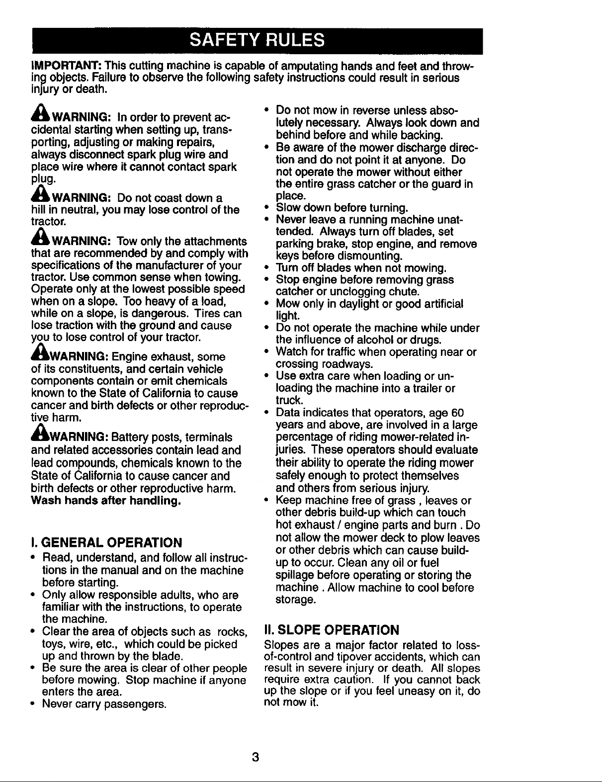
IMPORTANT: This cutting machine is capable of amputating hands and feet and throw-
!ng objects. Failure to observe the following safety instructions could result in serious
mjury or death.
&WARNING: In order to prevent ac-
cidental starting when setting up, trans-
porting, adjusting or making repairs,
always disconnect spark plug wire and
place wire where it cannot contact spark
plug.
_I_WARNING: Do not coast down a
hill in neutral, you may lose control of the
tractor.
_,WARNING: Tow only the attachments
that are recommended by and comply with
specifications of the manufacturer of your
tractor. Use common sense when towing.
Operate only at the lowest possible speed
when on a slope. Too heavy of a load,
while on a slope, is dangerous. Tires can
lose traction with the ground and cause
you to lose control of your tractor.
_,WARNING: Engine exhaust, some
of its constituents, and certain vehicle
components contain or emit chemicals
known to the State of California to cause
cancer and birth defects or other reproduc-
tive harm.
A
_I_WARNING: Battery posts, terminals
and related accessories contain lead and
lead compounds, chemicals known to the
State of California to cause cancer and
birth defects or other reproductive harm.
Wash hands after handling.
I. GENERAL OPERATION
• Read, understand, and follow all instruc-
tions in the manual and on the machine
before starting.
• Only allow responsible adults, who are
familiar with the instructions, to operate
the machine.
• Clear the area of objects such as rocks,
toys, wire, etc., which could be picked
up and thrown by the blade.
• Be sure the area is clear of other people
before mowing. Stop machine if anyone
enters the area.
• Never carry passengers.
• Do not mow in reverse unless abso-
lutely necessary. Always look down and
behind before and while backing.
• Be aware of the mower discharge direc-
tion and do not point it at anyone. Do
not operate the mower without either
the entire grass catcher or the guard in
place.
• Slow down before turning.
• Never leave a running machine unat-
tended. Always turn off blades, set
parking brake, stop engine, and remove
keys before dismounting.
• Turn off blades when not mowing.
• Stop engine before removing grass
catcher or unclogging chute.
• Mow only in daylight or good artificial
light.
• Do not operate the machine while under
the influence of alcohol or drugs.
• Watch for traffic when operating near or
crossing roadways.
• Use extra care when loading or un-
loading the machine into a trailer or
truck.
• Data indicates that operators, age 60
years and above, are involved in a large
percentage of riding mower-related in-
juries. These operators should evaluate
their ability to operate the riding mower
safely enough to protect themselves
and others from serious injury.
• Keep machine free of grass, leaves or
other debris build-up which can touch
hot exhaust / engine parts and burn. Do
not allow the mower deck to plow leaves
or other debris which can cause build-
up to occur. Clean any oil or fuel
spillage before operating or storing the
machine. Allow machine to cool before
storage.
II. SLOPE OPERATION
Slopes are a major factor related to loss-
of-control and tipover accidents, which can
result in severe injury or death. All slopes
require extra caution. If you cannot back
up the slope or if you feel uneasy on it, do
not mow it.
3
Page 4
DO:
• Mow up and down slopes, not across.
• Remove obstacles such as rocks, tree
limbs, etc.
• Watch for holes, ruts, or bumps. Un-
even terrain could overturn the machine.
Tall grass can hide obstacles.
• Use slow speed. Choose a low gear
so that you will not have to stop or shift
while on the slope.
• Follow the manufacturer's recommend-
ations for wheel weights or counter-
weights to improve stability.
• Use extra care with grass catchers or
other attachments. These can change
the stability of the machine.
• Keep all movement on the slopes slow
and graduaL Do not make sudden
changes in speed or direction.
• Avoid starting or stopping on a slope.
if tires lose traction, disengage the
blades and proceed slowly straight
down the slope.
DO NOT:
• Do not turn on slopes unless neces-
sary, and then, turn slowly and gradually
downhill, if possible.
• Do notmow near drop-offs, ditches,
or embankments. The mower could
suddenly turn over ifa wheel is over
the ed.ge of a cliff or ditch, or if an edge
caves in.
• Do not mow on wet grass. Reduced
traction could cause sliding.
• Do not try to stabilize the machine by
putting your foot on the ground.
• Do not use grass catcher on steep
slopes.
III. CHILDREN
Tragic accidents can occur if the operator
is not alert to the presence of children.
Children are often attracted to the ma-
chine and the mowing activity. Neveras-
sume that children will remain where you
last saw them.
• Keep children out of the mowing area
and under the watchful care of another
responsible adult.
• Be alert and turn machine off if children
enter the area.
• Before and when backing, look behind
and down for small children.
• Never carry children. They may fall off
and be seriously injured or interfere with
safe machine operation.
• Never allow children to operate the
machine.
• Use extra care when approaching blind
corners, shrubs, trees, or other objects
that may obscure vision.
IV. SERVICE
• Use extra care in handling gasoline and
other fuels. They are flammable and
vapors are explosive.
- Use only an approved container.
- Never remove gas cap or add fuel
with the engine running. Allow
engine to cool before refueling. Do
not smoke.
- Never refuel the machine indoors.
- Never store the machine or fuel
container inside where there is an
open flame, such as a water heater.
• Never run a machine inside a closed
area.
• Keep nuts and bolts, especially blade
attachment bolts, tight and keep equip-
ment in good condition.
• Never tamper with safety devices.
Check their proper operation regularly.
• Keep machine free of grass, leaves, or
other debris build-up. Clean oil or fuel
spillage. Allow machine to cool before
storing.
• Stop and inspect the equipment if you
strike an object. Repair, if necessary,
before restarting.
• Never make adjustments or repairs with
the engine running.
• Grass catcher components are subject
to wear, damage, and deterioration,
which could expose moving parts or
allow objects to be thrown. Frequently
check components and replace with
manufacturer's recommended parts,
when necessary.
• Mower blades are sharp and can cut.
Wrap the blade(s) or wear gloves, and
use extra caution when servicing them.
• Check brake operation frequently. Ad-
just and service as required.
4
Page 5

• Be sure the area is clear of other people
before mowing. Stop machine if anyone
enters the area.
• Never carry passengers or children
even with the blades off.
• Do not mow in reverse unless abso-
lutely necessary. Always look down and
behind before and while backing.
• Never carry children. They may fall off
and be seriously injured or interfere with
safe machine operation.
• Keep children out of the mowing area
and under the watchful care of another
responsible adult.
• Be alert and turn machine off if children
enter the area.
• Before and when backing, look behind
and down for small children.
• Mow up and down slopes (15 ° Max), not
across.
• Remove obstacles such as rocks, tree
limbs, etc.
• Watch for bores, ruts, or bumps. Uneven
terrain could overturn the machine. Tall
grass can hide obstacles.
• Use slow speed. Choose a low gear
so that you will not have to stop or shift
while on the slope.
• Avoid starting or stopping on a slope. If
tires lose traction, disengage the blades
and proceed slowly straight down the
slope.
• If machine stops while going uphill,
disengage blades, shift into reverse and
back down slowly.
• Do not turn on slopes unless necessary,
and then, turn slowly and gradually
downhill, if possible.
5
Page 6
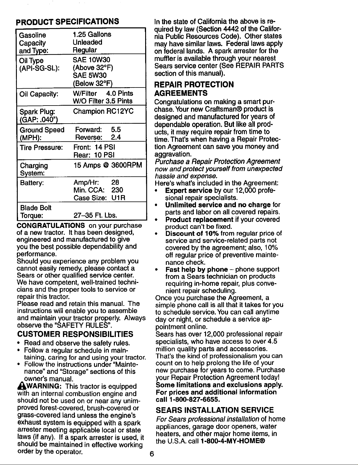
PRODUCT SPECIFICATIONS
Gasoline
Capacity
and Type:
Oil Type
(API-SG-SL):
Oil Capacity: W/Filter 4.0 Pints
Spark Plug: Champion RC12YC
(GAP: .040")
Ground Speed Forward: 5.5
(MPH): Reverse: 2.4
Tire Pressure: Front: 14 PSI
Charging 15 Amps @ 3600RPM
System:
Battery: Amp/Hr: 28
Blade Bolt
Torque: 27-35 Ft. Lbs.
CONGRATULATIONS on your purchase
of a new tractor. It has been designed,
engineered and manufactured to give
you the best possible dependability and
performance.
Should you experience any problem you
cannot easily remedy, please contact a
Sears or other qualified service center.
We have competent, well-trained techni-
cians and the proper tools to service or
repair this tractor.
Please read and retain this manual. The
instructions will enable you to assemble
and maintain your tractor properly. Always
observe the "SAFETY RULES".
CUSTOMER RESPONSIBILITIES
• Read and observe the safety rules.
• Follow a regular schedule in main-
taining, caring for and using your tractor.
• Follow the instructions under "Mainte-
nance" and "Storage" sections of this
owner's manual.
_WARNING: This tractor is equipped
with an internal combustion engine and
should not be used on or near any unim-
proved forest-covered, brush-covered or
grass-covered land unless the engine's
exhaust system is equipped with a spark
arraster meeting applicable local or state
laws (if any). If a spark arrester is used, it
should be maintained in effective working
order by the operator.
1.25 Gallons
Unleaded
Regular
SAE 10W30
(Above 32°F)
SAE 5W30
(Below 32°F)
W/O Filter 3.5 Pints
Rear: 10 PSI
Min. CCA: 230
Case Size: U1R
In the state of California the above is re-
quired by law (Section 4442 of the Califor-
nia Public Resources Code). Other states
may have similar laws. Federal laws apply
on federal lands. A spark arrester for the
muffler is available through your nearest
Sears service center (See REPAIR PARTS
section of this manual).
REPAIR PROTECTION
AGREEMENTS
Congratulations on making a smart pur-
chase. Your new Craftsman® product is
designed and manufactured for years of
dependable operation, But like all prod-
ucts, it may require repair from time to
time. That's when having a Repair Protec-
tion Agreement can save you money and
aggravation.
Purchase a Repair Protection Agreement
now and protect yourself from unexpected
hassle and expense.
Here's what's included in the Agreement:
• Expert service by our 12,000 profe-
sional repair specialists.
• Unlimited service and no charge for
parts and labor on all covered repairs.
• Product replacement ifyour covered
product can't be fixed.
• Discount of 10% from regular price of
service and service-related parts not
covered by the agreement; also, 10%
off regular price of preventive mainte-
nance check.
• Fast help by phone- phone support
from a Sears technician on products
requiring in-home repair, plus conve-
nient repair scheduling.
Once you purchase the Agreement, a
simple phone call is all that ittakes for you
to schedule service. You can call anytime
day or night, or schedule a service ap-
pointment online.
Sears has over 12,000 professional repair
specialists, who have access to over 4.5
million quality parts and accessories.
That's the kind of professionalism you can
count on to help prolong the life of your
new purchase for years to come. Purchase
your Repair Protection Agreement today!
Some limitations and exclusions apply.
For prices and additional information
call 1-800-827-6655.
SEARS INSTALLATION SERVICE
For Sears professiona/ insta//ationofhome
appliances,garage dooropeners, water
heaters, and other major home items, in
the U.S.A. call 1-800-4-MY-HOME®
6
Page 7
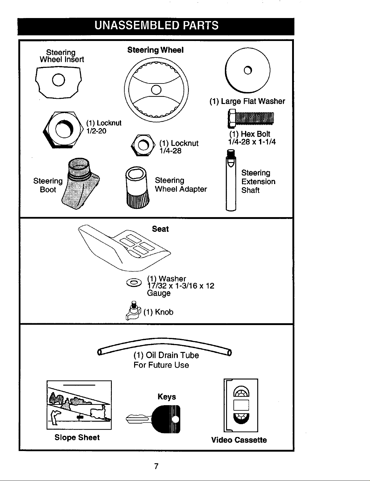
Steering
Wheel Insert
Steering
Boot
(1) Locknut
1/2-20
Steering Wheel
(1) Locknut
1/4-28
Steering
Wheel Adapter
(1) Large Flat Washer
(1) Hex Bolt
1/4-28 x 1-1/4
Steering
Extension
Shaft
Slope Sheet
(1) Washer
17/32 x 1-3/16 x 12
Gauge
_i_ (1) Knob
(_1_(1) Oil Drain_
For Future Use
Keys
Video Cassette
7
Page 8
Your new tractor has been assembled at the factory with the exception of those parts left
unassembled for shipping purposes. To ensure safe and proper operation of your tractor
all parts and hardware you assemble must be tightened securely. Use the correct tools
as necessary to insure proper tightness. Review the video cassette before you begin.
TOOLS REQUIRED FOR
ASSEMBLY
_._ Insert
A socket wrench set will make assembly
easier, Standard wrench sizes are listed.
(1) 3/4" wrench Pliers
_1/2 Rex Nut
LargeFlatWasher
(2) 7/16" wrenches Utility knife
Tire pressure gauge
When right or left hand is mentioned in
this manual, it means when you are m
the operating position (seated behind the
steering wheel).
TO REMOVE TRACTOR FROM
CARTON
UNPACK CARTON
1. Remove all accessible loose parts and
parts boxes from carton.
2. Cut along dotted lines on all four pan-
els of carton. Remove end panels and
lay side panels flat.
3. Check for any additional loose parts or
cartons and remove.
BEFORE REMOVING TRACTOR
FROM SKID
ATTACH STEERING WHEEL
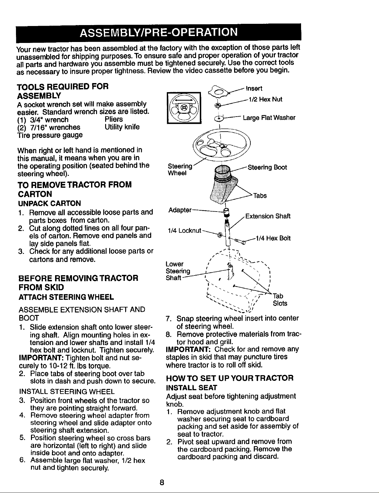
ASSEMBLE EXTENSION SHAFT AND
BOOT
1. Slide extension shaft onto lower steer-
ing shaft. Align mounting holes in ex-
tension and lower shafts and install 1/4
hex bolt and Iocknut. Tighten securely.
IMPORTANT" Tighten bolt and nut se-
curely to 10-12 ft. Ibs torque.
2. Place tabs of steering boot over tab
slots in dash and push down to secure.
INSTALL STEERING WHEEL
3. Position front wheels of the tractor so
they are pointing straight forward.
4. Remove steering wheel adapter from
steering wheel and slide adapter onto
steering shaft extension•
5. Position steering wheel so cross bars
are horizontal (left to right) and slide
inside boot and onto adapter.
6. Assemble large flat washer, 1/2 hex
nut and tighten securely.
Steering/@ eering Boot
Wheel
_Tabs
Adapter---------_
_/Extension Shaft
1/4 Locknut---_...._ 1
_'_1/4 Hex Bolt
Lower _ _ "_--" "-
• I
Steenng _ . '_
Shaff----_""_l\ • _/ ' ,'
- - - -, F lau
",.. -. _ Slots
7, Snap steering wheel insert into center
of steering wheel.
8, Remove protective materials from trac-
tor hood and grill.
IMPORTANT: Check for and remove any
staples in skid that may puncture tires
where tractor is to roll off skid.
HOW TO SET UP YOUR TRACTOR
INSTALL SEAT
Adjust seat before tightening adjustment
knob.
1. Remove adjustment knob and flat
washer securing seat to cardboard
packing and set aside for assembly of
seat to tractor.
2. Pivot seat upward and remove from
the cardboard packing. Remove the
cardboard packing and discard.
8
Page 9
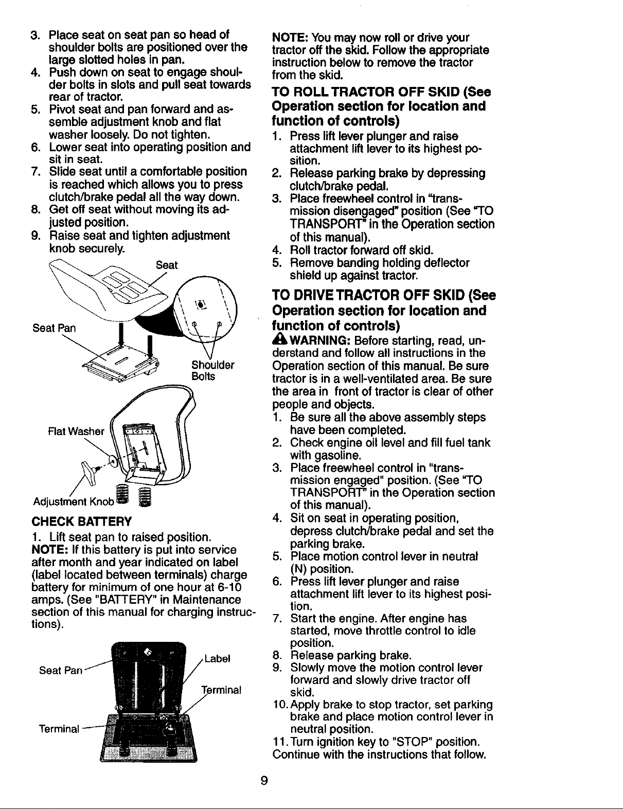
3. Place seat on seat pan so head of
shoulder bolts are positioned over the
large slotted holes in pan.
4. Push down on seat to engage shoul-
der bolts in slots and pull seat towards
rear of tractor.
5. Pivot seat and pan forward and as-
semble adjustment knob and flat
washer loosely. Do not tighten.
6. Lower seat into operating position and
sit in seat.
7. Slide seat until a comfortable position
is reached which allows you to press
clutch/brake pedal all the way down.
8. Get off seat without moving its ad-
justed position.
9. Raise seat and tighten adjustment
knob securely.
Seat
Seat Pan
Shoulder
Bolts
FlatWasher
Adjl
CHECK BATTERY
1. Lift seat pan to raised position.
NOTE: If this battery is put into service
after month and year indicated on label
(label located between terminals) charge
battery for minimum of one hour at 6-10
amps. (See "BATTERY" in Maintenance
section of this manual for charging instruc-
tions).
erminal
NOTE: You may now roll or drive your
tractor off the skid. Follow the appropriate
instruction below to remove the tractor
from the skid.
TO ROLL TRACTOR OFF SKID (See
Operation section for location and
function of controls)
1. Press lift lever plunger and raise
attachment liftlever to its highest po-
sition.
2. Release parking brake by depressing
clutch/brake pedal.
3. Place freewheel control in "trans-
mission disengaged" position (See "TO
TRANSPORT" in the Operation section
of this manual).
4. Roll tractor forward off skid.
5. Remove banding holding deflector
shield up against tractor.
TO DRIVETRACTOROFF SKID (See
Operation section for location and
function of controls)
_WARNING: Before starting, read, un-
derstand and follow all instructions in the
Operation section of this manual. Be sure
tractor is in a well-ventilated area. Be sure
the area in front of tractor is clear of other
people and objects.
1. Be sure all the above assembly steps
have been completed.
2. Check engine oil level and fill fuel tank
with gasoline.
3. Place freewheel control in "trans-
mission engaged" position. (See =TO
TRANSPORT" in the Operation section
of this manual).
4. Sit on seat in operating position,
depress clutch/brake pedal and set the
parking brake.
5. Place motion control lever in neutral
(N) position.
6. Press lift lever plunger and raise
attachment lift lever to its highest posi-
tion.
7. Start the engine. After engine has
started, move throttle control to idle
position.
8. Release parking brake.
9. Slowly move the motion control lever
forward and slowly drive tractor off
skid.
10.Apply brake to stop tractor, set parking
brake and place motion control lever in
neutral position.
11.Turn ignition key to "STOP" position.
Continue with the instructions that follow.
9
Page 10
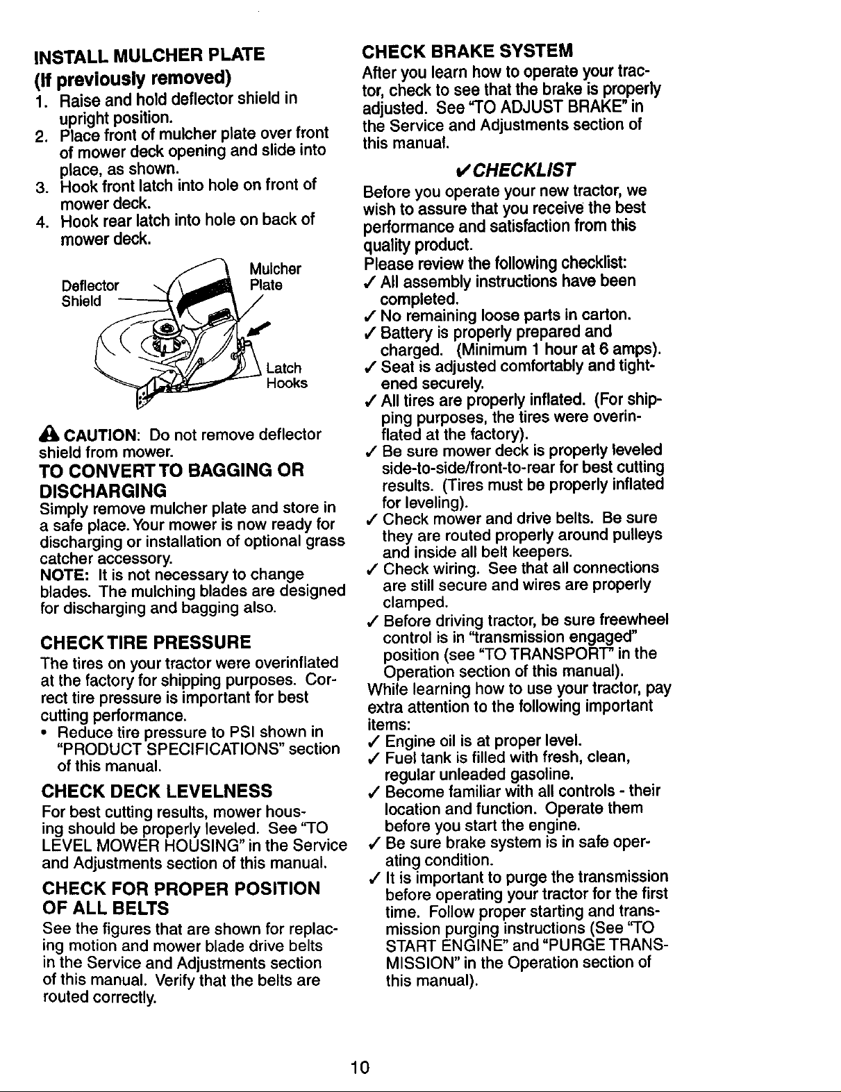
INSTALL MULCHER PLATE
(If previously removed)
1. Raise and hold deflector shield in
upright position.
2. Place front of mulcher plate over front
of mower deck opening and slide into
place, as shown.
3. Hook front latch into hole on front of
mower deck.
4. Hook rear latch into hole on back of
mower deck.
Mulcher
Deflector
Shield
_k CAUTION: Do not remove deflector
shield from mower.
TO CONVERTTO BAGGING OR
DISCHARGING
Simply remove mulcher plate and store in
a safe place. Your mower is now ready for
discharging or installation of optional grass
catcher accessory.
NOTE: It is not necessary to change
blades. The mulching blades are designed
for discharging and bagging also.
CHECKTIRE PRESSURE
The tires on your tractor were overinflated
at the factory for shipping purposes. Cor-
rect tire pressure is important for best
cutting performance.
• Reduce tire pressure to PSI shown in
"PRODUCT SPECIFICATIONS" section
of this manual.
Plate
Latch
Hooks
CHECK DECK LEVELNESS
For best cutting results, mower hous-
ing should be properly leveled. See "TO
LEVEL MOWER HOUSING" in the Service
and Adjustments section of this manual.
CHECK FOR PROPER POSITION
OF ALL BELTS
See the figures that are shown for replac-
ing motion and mower blade drive belts
in the Service and Adjustments section
of this manual. Verify that the belts are
routed correctly.
CHECK BRAKE SYSTEM
After you learn howto operate yourtrac-
tor, checkto see thatthe brake is properly
adjusted. See "TO ADJUST BRAKE"in
the Service and Adjustmentssectionof
thismanual.
o/CHECKLIST
Before you operate your new tractor, we
wish to assure that you receive the best
performance and satisfaction from this
quality product.
Please review the following checklist:
•/ All assembly instructions have been
completed.
,/No remaining loose parts in carton.
4 Battery is properly prepared and
charged. (Minimum 1 hour at 6 amps).
/ Seat is adjusted comfortably and tight-
ened securely.
,/All tires are properly inflated. (For ship-
ping purposes, the tires were overin-
flated at the factory).
,/Be sure mower deck is properly leveled
side-to-side/front-to-rear for best cutting
results. (Tires must be properly inflated
for leveling).
,/Check mower and drive belts. Be sure
they are routed properly around pulleys
and inside all belt keepers.
,/Check wiring. See that all connections
are still secure and wires are properly
clamped.
,/Before driving tractor, be sure freewheel
control is in "transmission engaged"
position (see "TO TRANSPORT" in the
Operation section of this manual).
While learning how to use your tractor, pay
extra attention to the following important
items:
,/Engine oil is at proper level.
,/Fuel tank is filled with fresh, clean,
regular unleaded gasoline.
,/Become familiar with all controls - their
location and function. Operate them
before you start the engine.
,/Be sure brake system is in safe oper-
ating condition.
/ It is important to purge the transmission
before operating your tractor for the first
time. Follow proper starting and trans-
mission purging instructions (See 'q'O
START ENGINE" and "PURGE TRANS-
MISSION" in the Operation section of
this manual).
10
Page 11
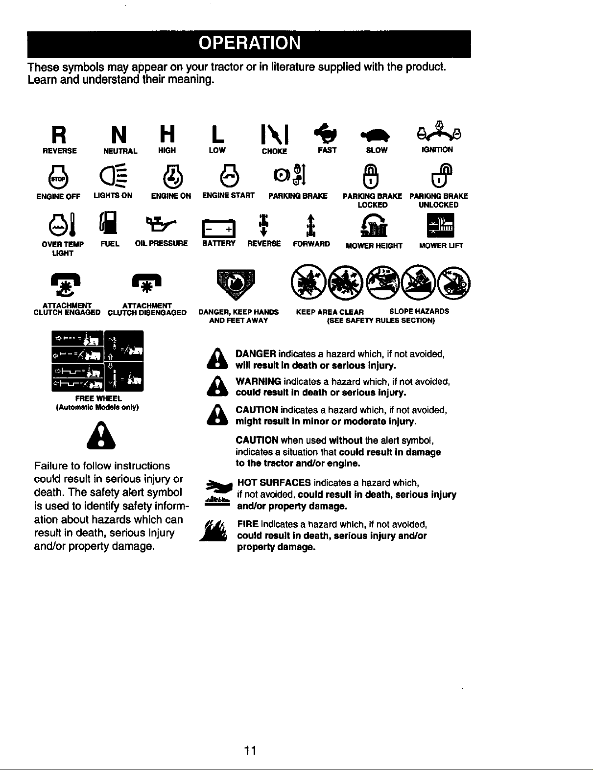
These symbolsmay appearon your tractororin literaturesupplied withthe product.
Learnand understandtheirmeaning.
R N H L I\1
REVERSE NEUTRAL HIGH LOW CHOKE FAST SLOW IGNITION
ENGINE OFF LIGHTS ON ENGINE ON ENGINE START PARKING BRAKE PARKING BRAKE PARKING BRAKE
OVER TEMP FUEL OIL PRESSURE BATTERY REVERSE FORWARD MOWER HEIGHT MOWER UFT
UGHT
AITACHMENT ATTACHMENT
CLUTCH ENGAGED CLUTCH DISENGAGED
FREEWHEEL
(Automatic Models only)
DANGER, KEEP HANDS
&
Failure to follow instructions
could result in serious injury or
death. The safety alert symbol
is used to identify safety inform-
ation about hazards which can
result in death, serious injury J_
and/or property damage.
AND FEET AWAY
DANGER indicatesa hazard which, ifnot avoided,
&
will result in death or serious Injury.
WARNING indicates a hazard which, if not avoided,
&
could result in death or serious injury.
CAUTION indicates a hazard which, if not avoided,
&
might result in minor or moderate injury.
CAUTION when used without the alert symbol,
indicatesa situation thatcould result in damage
to the tractor and/or engine.
HOT SURFACES indicatesa hazard which,
ifnot avoided,could result in death, serious injury
and/or property damage.
FIRE indicatesa hazard which, if not avoided,
could result in death, serious injury and/or
property damage.
KEEP AREA CLEAR SLOPE HAZARDS
(SEE SAFETY RULES SECTION)
LOCKED UNLOCKED
11
Page 12
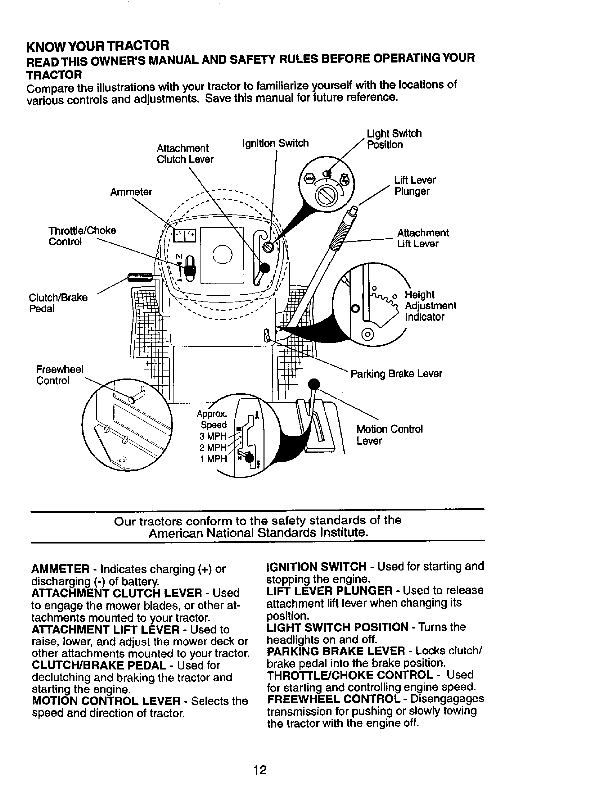
KNOW YOUR TRACTOR
READTHIS OWNER'S MANUAL AND SAFETY RULES BEFORE OPERATINGYOUR
TRACTOR
Compare the illustrations with your tractor to familiarize yourseff with the locations of
various controls and adjustments. Save this manual for future reference.
Light Switch
Attachment
Clutch Lever
Ammeter
Ignition Switch
Lift Lever
J Plunger
Throttle/Choke
Control
Clutch/Brake
Pedal
Freewheel
Control
Attachment
Lift Lever
Height
Adjustment
Indicator
Parking Brake Lever
MotionControl
Lever
Our tractors conform to the safety standards of the
American National Standards Institute.
AMMETER - Indicates charging (+) or
discharging (°) of battery.
ATTACHMENT CLUTCH LEVER - Used
to engage the mower blades, or other at-
tachments mounted to your tractor.
ATTACHMENT LIFT LEVER - Used to
raise, lower, and adjust the mower deck or
other attachments mounted to your tractor.
CLUTCH/BRAKE PEDAL - Used for
declutching and braking the tractor and
starting the engine.
MOTION CONTROL LEVER - Selects the
speed and direction of tractor.
IGNITION SWITCH - Used for starting and
stopping the engine.
LIFT LEVER PLUNGER - Used to release
attachment lift lever when changing its
position.
LIGHT SWITCH POSITION - Turns the
headlights on and off.
PARKING BRAKE LEVER - Locks clutch/
brake pedal into the brake position.
THROTTLE/CHOKE CONTROL - Used
for starting and controlling engine speed.
FREEWHEEL CONTROL - Disengagages
transmission for pushing or slowly towing
the tractor with the engine off.
12
Page 13
The operation of any tractor can result in foreign objects thrown into the
eyes, which can result in severe eye damage. Always wear safety glasses I
or eye shields while operating your tractor or performing any adjustments I
or repairs. We recommend standard safety glasses or a wide vision safety I
mask worn over spectacles. I
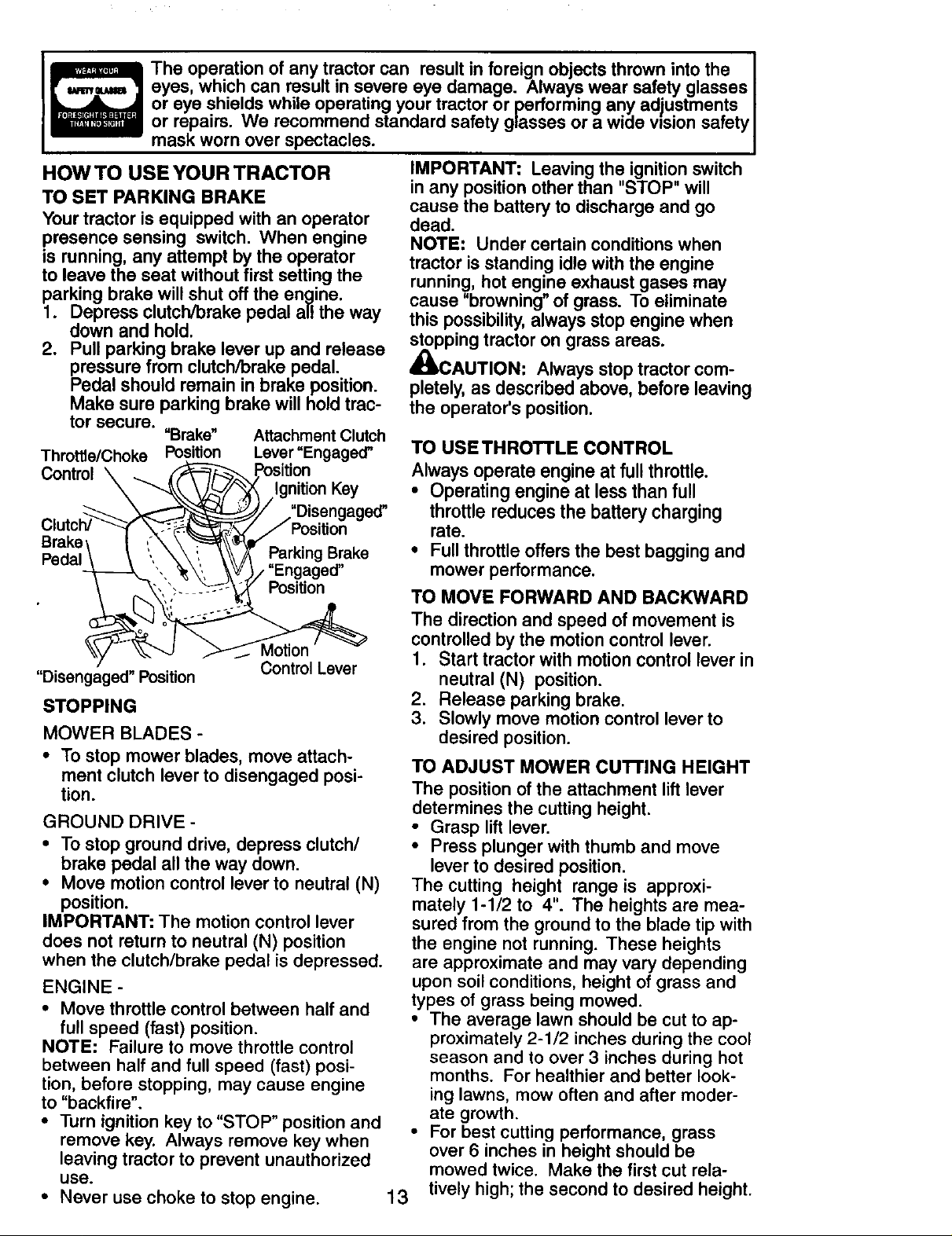
HOW TO USE YOUR TRACTOR
TO SET PARKING BRAKE
Your tractor is equipped with an operator
presence sensing switch. When engine
is running, any attempt by the operator
to leave the seat without first setting the
parking brake will shut off the engine.
1. Depress clutch/brake pedal all the way
down and hold.
2. Pull parking brake lever up and release
pressure from clutch/brake pedal.
Pedal should remain in brake position.
Make sure parking brake will hold trac-
tor secure.
Throttle/Choke
Control
Brake
Pedal Parking Brake
"Disengaged" Position Control Lever
STOPPING
MOWER BLADES -
• To stop mower blades, move attach-
ment clutch lever to disengaged posi-
tion.
GROUND DRIVE -
• To stop ground drive, depress clutch/
brake pedal all the way down.
• Move motion control lever to neutral (N)
position.
IMPORTANT: The motion control lever
does not return to neutral (N) position
when the clutch/brake pedal is depressed.
ENGINE -
• Move throttle control between half and
full speed (fast) position.
NOTE: Failure to move throttle control
between half and full speed (fast) posi-
tion, before stopping, may cause engine
to "backfire".
• Turn ignition key to "STOP" position and
remove key. Always remove key when
leaving tractor to prevent unauthorized
use.
• Never use choke to stop engine.
"Brake" Attachment Clutch
Position Lever "Engaged"
Key
"Disengaged"
Position
IMPORTANT: Leaving the ignition switch
in any position other than "STOP" will
cause the battery to discharge and go
dead.
NOTE: Under certain conditions when
tractor is standing idle with the engine
running, hot engine exhaust gases may
cause "browning" of grass. To eliminate
this possibility, always stop engine when
stopping tractor on grass areas.
_J_CAUTION: Always stop tractor com-
pletely, as described above, before leaving
the operator's position.
TO USETHROTTLE CONTROL
Always operate engine at full throttle.
• Operating engine at less than full
throttle reduces the battery charging
rate.
• Full throttle offers the best bagging and
mower performance.
TO MOVE FORWARD AND BACKWARD
The direction and speed of movement is
controlled by the motion control lever.
1. Start tractor with motion control lever in
neutral (N) position.
2, Release parking brake,
3. Slowly move motion control lever to
desired position.
TO ADJUST MOWER CU'I-rlNG HEIGHT
The position of the attachment lift lever
determines the cutting height.
• Grasp lift lever.
• Press plunger with thumb and move
lever to desired position.
The cutting height range is approxi-
mately 1-1/2 to 4". The heights are mea-
sured from the ground to the blade tip with
the engine not running. These heights
are approximate and may vary depending
upon soil conditions, height of grass and
types of grass being mowed.
• The average lawn should be cut to ap-
proximately 2-1/2 inches during the cool
season and to over 3 inches during hot
months. For healthier and better look-
ing lawns, mow often and after moder-
ate growth.
• For best cutting performance, grass
over 6 inches in height should be
mowed twice. Make the first cut rela-
tively high; the second to desired height.
13
Page 14
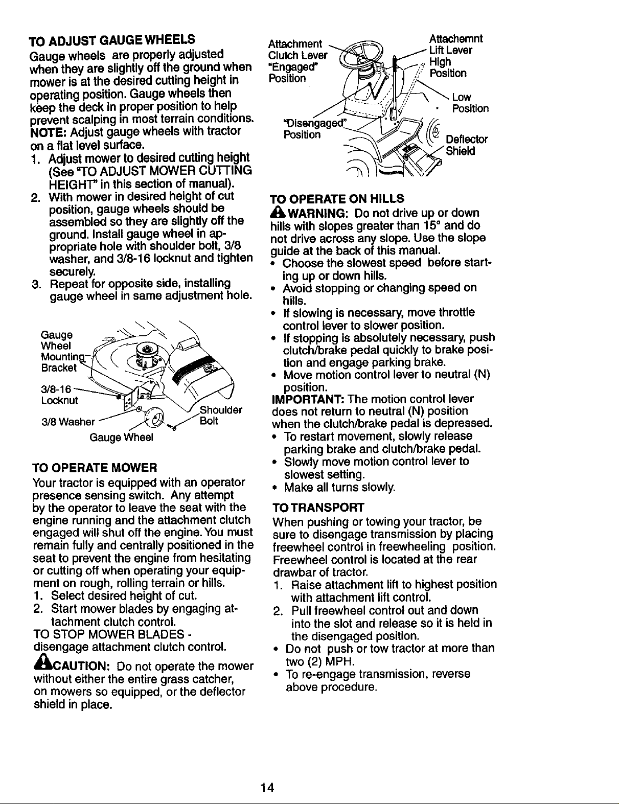
TO ADJUST GAUGEWHEELS
Gauge wheels are properly adjusted
when they are slightly off the ground when
mower is at the desired cutting height in
operating position. Gauge wheels then
ke'ep the-deck ,n proper pos'tion to help
prevent scalping in most terrain conditions.
NOTE: Adjust gauge wheels with tractor
on a flat level surface.
I. Adjust mower to desired cutting height
(See "TO ADJUST MOWER CUTTING
HEIGHT" in this section of manual).
2. With mower in desired height of cut
position, gauge wheels should be
assembled so they are slightly off the
ground. Install gauge wheel in ap-
propriate hole with shoulder bolt, 3/8
washer, and 3/8-1 6 Iocknut and tighten
securely.
3. Repeat for opposite side, installing
gauge wheel in same adjustment hole.
Gauge --_.,_--J-_
Wheel _"_-I_ _,,
Mountin_.-_ (" _.X_
3/V-16
Locknut _ r
318Washer f ..._,,
GaugeWheel
TO OPERATE MOWER
Your tractor is equipped with an operator
presence sensing switch. Any attempt
by the operator to leave the seat with the
engine running and the attachment clutch
engaged will shut off the engine. You must
remain fully and centrally positioned in the
seat to prevent the engine from hesitating
or cutting off when operating your equip-
ment on rough, rolling terrain or hills.
1. Select desired height of cut.
2. Start mower blades by engaging at-
tachment clutch control.
TO STOP MOWER BLADES -
disengage attachment clutch control.
/=.
_uLCAUTION: Do not operate the mower
without either the entire grass catcher,
on mowers so equipped, or the deflector
shield in place.
Attachment Attachemnt
=Engaged" High
Position _? Position
Position
Position
Deflector
TO OPERATE ON HILLS
_kWARNING: Do not drive up or down
hills with slopes greater than 15° and do
not drive across any slope. Use the slope
guide at the back of this manual.
• Choose the slowest speed before start-
ing up or down hills.
• Avoid stopping or changing speed on
hills.
• If slowing is necessary, move throttle
control lever to slower position.
• If stopping is absolutely necessary, push
clutch/brake pedal quickly to brake posi-
tion and engage parking brake.
• Move motion control lever to neutral (N)
position.
IMPORTANT: The motion control lever
does not return to neutral (N) position
when the clutch/brake pedal is depressed.
• To restart movement, slowly release
parking brake and clutch/brake pedal.
• Slowly move motion control lever to
slowest setting.
• Make all turns slowly.
TO TRANSPORT
When pushing or towing your tractor, be
sure to disengage transmission by placing
freewheel control in freewheeling position.
Freewheel control is located at the rear
drawbar of tractor.
1. Raise attachment liftto highest position
with attachment lift control.
2. Pull freewheel control out and down
into the slot and release so it is held in
the disengaged position.
• Do not push or tow tractor at more than
two (2) MPH.
• To re-engage transmission, reverse
above procedure.
14
Page 15
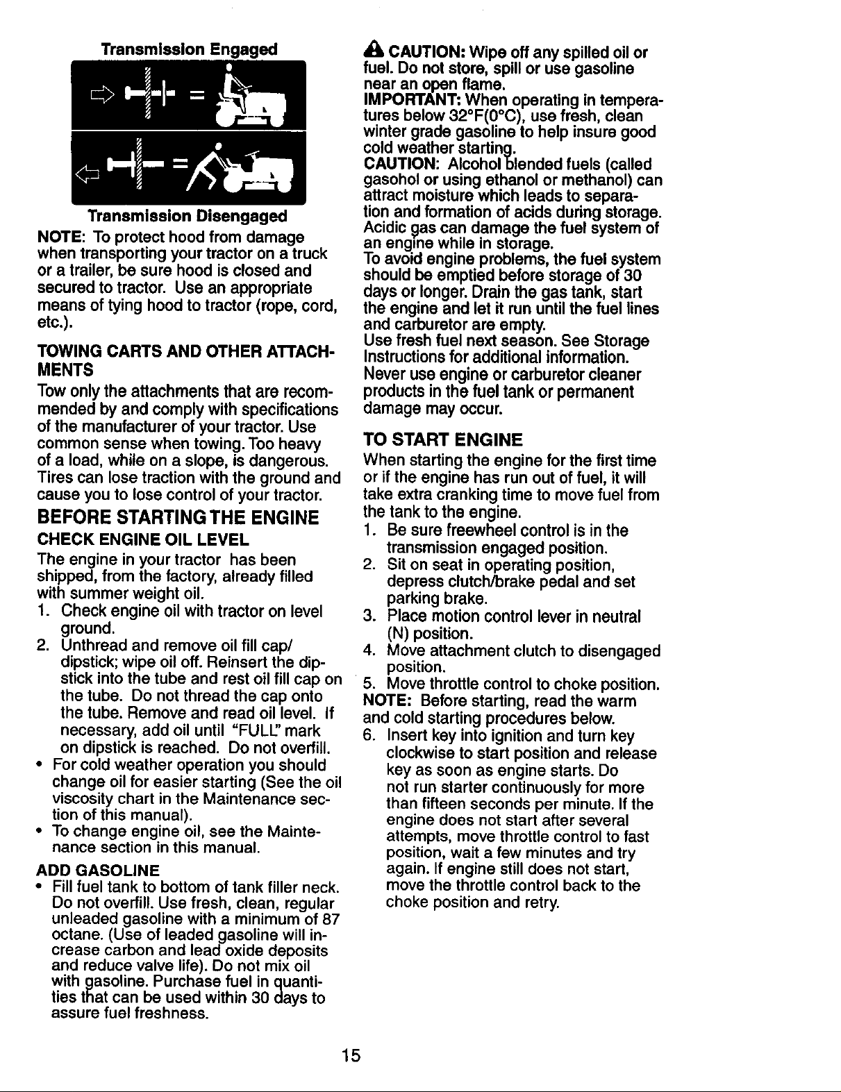
Transmlsslon Engaged
Transmission Disengaged
NOTE: To protect hood from damage
when transporting your tractor on a truck
or a trailer, be sure hood is closed and
secured to tractor. Use an appropriate
means of tying hood to tractor (rope, cord,
etc.).
TOWING CARTS AND OTHER ATTACH-
MENTS
Towonlythe attachmentsthat are recom-
mended byand complywith specifications
ofthe manufacturerofyourtractor.Use
commonsense when towing.Tooheavy
ofa load, while on a slope,is dangerous.
Tires can losetractionwiththe groundand
cause you to lose control of yourtractor.
BEFORE STARTING THE ENGINE
CHECK ENGINE OIL LEVEL
The engine in your tractor has been
shipped, from the factory, already filled
with summer weight oil.
1. Check engine oil with tractor on level
ground.
2. Unthraad and remove oil fill cap/
dipstick; wipe oil off. Reinsert the dip-
stick into the tube and rest oil fill cap on
the tube. Do not thread the cap onto
the tube. Remove and read oil level. If
necessary, add oil until "FULL" mark
on dipstick is reached. Do not overfill.
• For cold weather operation you should
change oil for easier starting (See the oil
viscosity chart in the Maintenance sec-
tion of this manual).
• To change engine oil, see the Mainte-
nance section in this manual.
ADD GASOLINE
• Fill fuel tank to bottom of tank filler neck.
Do not overfill. Use fresh, clean, regular
unleaded gasoline with a minimum of 87
octane. (Use of leaded gasoline will in-
crease carbon and lead oxide deposits
and reduce valve life). Do not mix oil
with gasoline. Purchase fuel in quanti-
ties that can be used within 30 days to
assure fuel freshness.
CAUTION: Wipe off any spilled oilor
fuel. Do not store, spill or use gasoline
near an open flame.
IMPORTANT: When operating in tempera-
tures below 32°F(0°C), use fresh, clean
winter grade gasoline to help insure good
cold weather starting.
CAUTION: Alcoholblended fuels (called
gasohol or using ethanol or methanol) can
attract moisture which leads to separa-
tion and formation of acids during storage.
Acidic gas can damage the fuel system of
an engine while in storage.
To avoid engine problems, the fuel system
should be emptied before storage of 30
days or longer. Drain the gas tank, start
the engine and let it run until the fuel lines
and carburetor are empty.
Use fresh fuel next season. See Storage
Instructions for additional information.
Never use engine or carburetor cleaner
products in the fuel tank or permanent
damage may occur.
TO START ENGINE
When starting the engine for the first time
or if the engine has run out of fuel, itwill
take extra cranking time to move fuel from
the tank to the engine.
1. Be sure freewheel control is in the
transmission engaged position.
2, Sit on seat in operating position,
depress clutch/brake pedal and set
parking brake.
3. Place motion control lever in neutral
(N) position.
4. Move attachment clutch to disengaged
position.
5. Move throttle control to choke position.
NOTE: Before starting, read the warm
and cold starting procedures below.
6. Insert key into ignition and turn key
clockwise to start position and release
key as soon as engine starts. Do
not run starter continuously for more
than fifteen seconds per minute. If the
engine does not start after several
attempts, move throttle control to fast
position, wait a few minutes and try
again. If engine still does not start,
move the throttle control back to the
choke position and retry.
15
Page 16
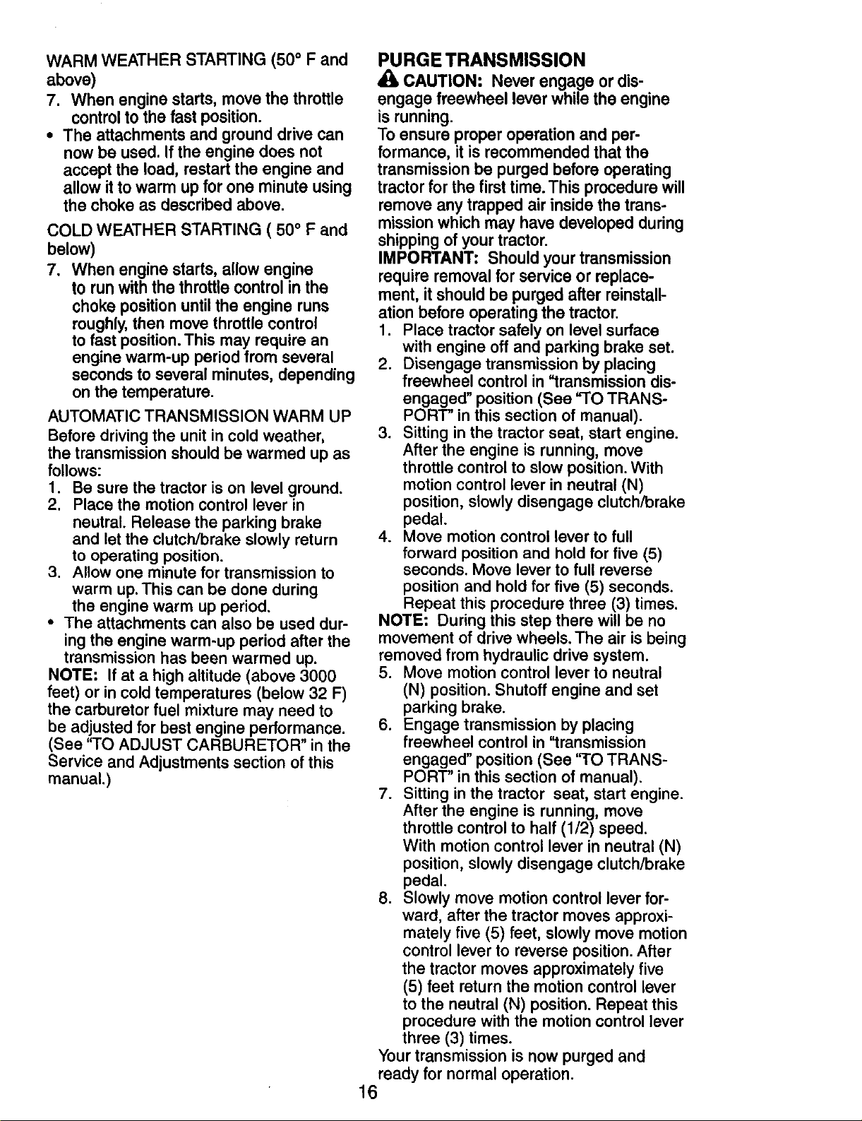
WARM WEATHER STARTING (50 ° F and
above)
7. When engine starts, move the throttle
control to the fast position.
• The attachments and ground drive can
now be used. If the engine does not
accept the load, restart the engine and
allow it to warm up for one minute using
the choke as described above.
COLD WEATHER STARTING ( 50° F and
below)
7. When engine starts, allow engine
to run with the throttle control in the
choke position until the engine runs
roughly, then move throttle control
to fast position. This may require an
engine warm-up period from several
seconds to several minutes, depending
on the temperature.
AUTOMATIC TRANSMISSION WARM UP
Before driving the unit in cold weather,
the transmission should be warmed up as
follows:
1. Be sure the tractor is on level ground.
2. Place the motion control lever in
neutral. Release the parking brake
and let the clutch/brake slowly return
to operating position.
3. Allow one minute for transmission to
warm up.This can be done during
the engine warm up period.
• The attachments can also be used dur-
ing the engine warm-up period after the
transmission has been warmed up.
NOTE: If at a high altitude (above 3000
feet) or in cold temperatures (below 32 F)
the carburetor fuel mixture may need to
be adjusted for best engine performance.
(See "TO ADJUST CARBURETOR" in the
Service and Adjustments section of this
manual.)
PURGE TRANSMISSION
CAUTION: Never engage or dis-
engage freewheel lever while the engine
is running.
To ensure proper operation and per-
formance, it is recommended that the
transmission be purged before operating
tractor for the first time. This procedure will
remove any trapped air inside the trans-
mission which may have developed during
shipping of your tractor.
IMPORTANT: Should your transmission
require removal for service or replace-
ment, it should be purged after reinstall-
ation before operating the tractor.
1. Place tractor safely on level surface
with engine off and parking brake set.
2. Disengage transmission by placing
freewheel control in "transmission dis-
engaged" position (See =TO TRANS-
PORT" in this section of manual).
3. Sitting in the tractor seat, start engine.
After the engine is running, move
throttle control to slow position. With
motion control lever in neutral (N)
position, slowly disengage clutch/brake
pedal.
4. Move motion control lever to full
forward position and hold for five (5)
seconds. Move lever to full reverse
position and hold for five (5) seconds.
Repeat this procedure three (3) times.
NOTE: During this step there will be no
movement of drive wheels. The air is being
removed from hydraulic drive system.
5. Move motion control lever to neutral
(N) position. Shutoff engine and set
parking brake.
6. Engage transmission by placing
freewheel control in "transmission
engaged" position (See 'riO TRANS-
PORT' in this section of manual).
7. Sitting in the tractor seat, start engine.
After the engine is running, move
throttle control to half (1/2) speed.
With motion control lever in neutral (N)
position, slowly disengage clutch/brake
pedal.
8. Slowly move motion control lever for-
ward, after the tractor moves approxi-
mately five (5) feet, slowly move motion
control lever to reverse position. After
the tractor moves approximately five
(5) feet return the motion control lever
to the neutral (N) position. Repeat this
procedure with the motion control lever
three (3) times.
Your transmission is now purged and
ready for normal operation.
16
Page 17
MOWING TIPS
• Mower should be properly leveled for
best mowing performance. See "TO
LEVEL MOWER HOUSING" in the
Service and Adjustments section of this
manual.
• The left hand side of mower should be
used for trimming.
• Drive so that clippings are discharged
onto the area that has already been cut.
Have the cut area to the right of the trac-
tor. This will result in a more even distri-
bution of clippings and more uniform
cutting.
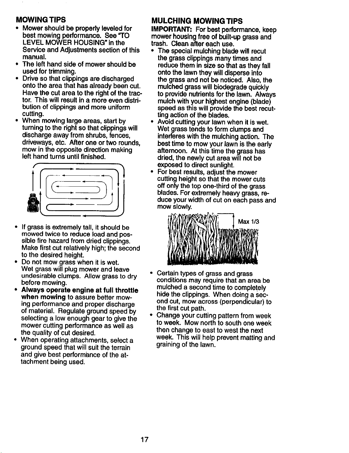
• When mowing large areas, start by
turning to the right so that clippings will
discharge away from shrubs, fences,
driveways, etc. After one or two rounds,
mow in the opposite direction making
left hand turns until finished.
f
.Ip
1
t
II
J
MULCHING MOWING TIPS
IMPORTANT: Forbest performance,keep
mowerhousingfree of built-upgrassand
trash. Clean after each use,
• The special mulchingblade willrecut
the grass clippings many times and
reduce them in size so that as they fall
onto the lawn they will disperse into
the grass and not be noticed. Also, the
mulched grass will biodegrade quickly
to provide nutrients for the lawn. Always
mulch with your highest engine (blade)
speed as this will provide the best recut-
ting action of the blades,
Avoid cutting your lawn when it is wet,
Wet grass tends to form clumps and
interferes with the mulching action. The
best time to mow your lawn is the early
afternoon. At this time the grass has
dried, the newly cut area will not be
exposed to direct sunlight.
For best results, adjust the mower
cutting height so that the mower cuts
off only the top one-third of the grass
blades. For extremely heavy grass, re-
duce your width of cut on each pass and
mow slowly.
• If grass is extremely tall, itshould be
mowed twice to reduce load and pos-
sible fire hazard from dried clippings.
Make first cut relatively high; the second
to the desired height.
• Do not mow grass when it is wet.
Wet grass will plug mower and leave
undesirable clumps. Allow grass to dry
before mowing.
• Always operate engine at full throttle
when mowing to assure better mow-
ing performance and proper discharge
of material. Regulate ground speed by
selecting a low enough gear to give the
mower cutting performance as well as
the quality of cut desired.
• When operating attachments, select a
ground speed that will suit the terrain
and give best perform_,nce of the at-
tachment being used.
• Certain types of grass and grass
conditions may require that an area be
mulched a second time to completely
hide the clippings. When doing a sec-
ond cut, mow across (perpendicular) to
the first cut path.
• Change your cutting pattern from week
to week. Mow north to south one week
then change to east to west the next
week. This will help prevent matting and
graining of the lawn.
17
Page 18
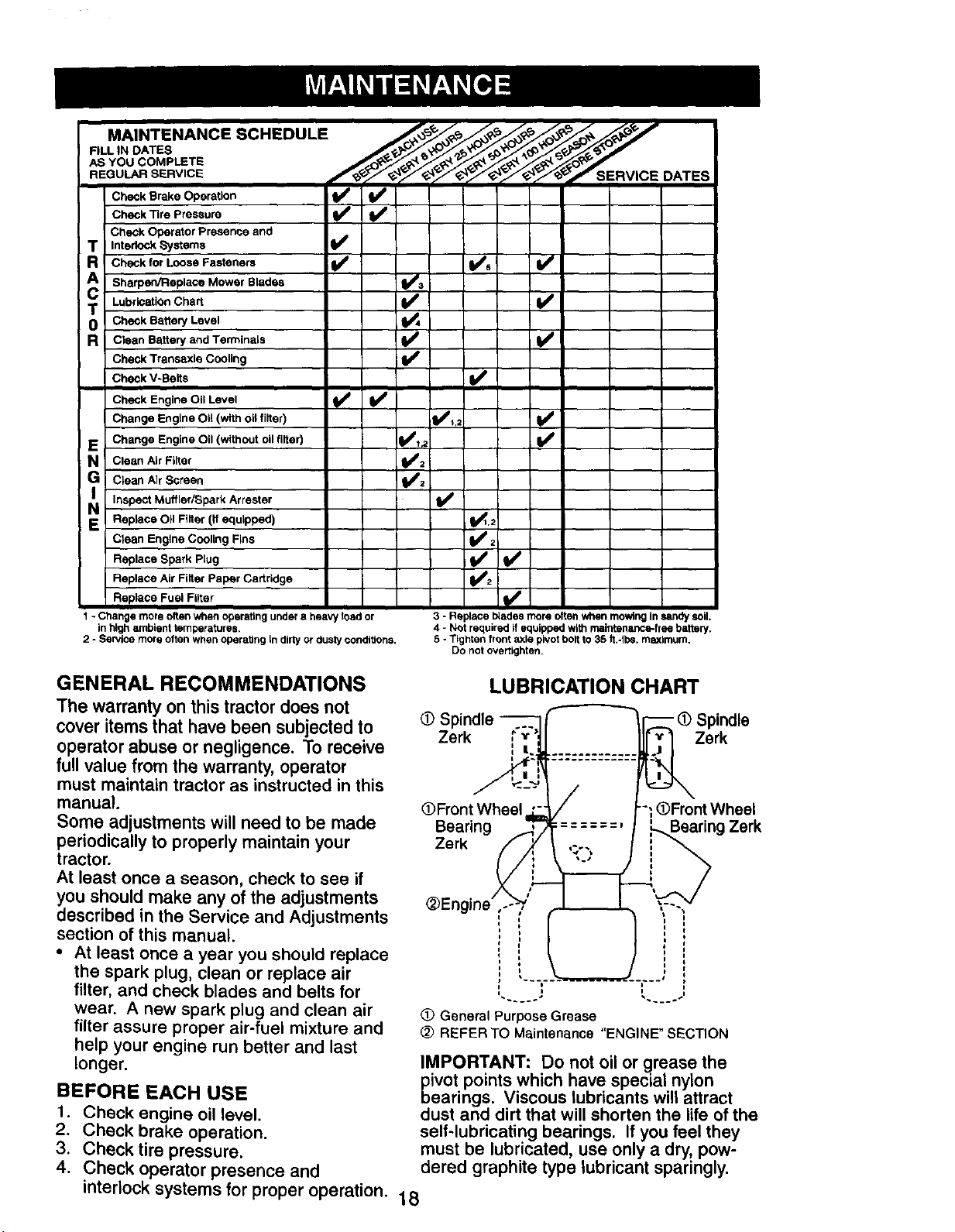
MAINTENANCE SCHEDULE _ ,_. _ ,_. _o_ ,_ ,_
AS YOU COMPLETE _ ._e _._q_ _> _, _ _
REGULAR SERVICE DATES
Check Brake Operation _
Check Tire Pressure
Check Operator Presence and
T InterlockSystems t_
R Check for Loose Fasteners _ l_s I_
T Lubrication Chart
0 Check Battery Level
A Sharpec/Replace Mower Blades _a
R Clean Battery and Terminals I_
Check Transaxle Cooling I_
Check V-Belts I_'
Check Engine Oil Level tf V'
Change Engine 011 (with OHfilter) I_,;
E Change Engine Oil (without oil filter) I_IR
N Clean AirFilter
G Clean Air Screen
Inspect Muffler/Spark Arrester
E Replace Oil Filter (if equipped) 1_,2
Clean Engine Cooling Fins _ 2
Replace Spark Plug _ l# #
Replace Air Filter Paper Cartridge
Replace Fuel Filter if #
1 - Change more often when operating under a heavy load or
in high ambient temperatures.
2 - Service more often when operating in dirtyor dusty condittens,
3 - Replace blades more often when mowing In sandy soil.
4 - Not required if equipped with maintenance-free battery.
5 - Tighten front axle pivot bolt to 35 It.-Ibe. maximum.
Do not overtighten.
,/
GENERAL RECOMMENDATIONS
LUBRICATION CHART
The warranty on this tractor does not
cover items that have been subjected to
(D Spindle -- _) Spindle
Zerk Zerk
operator abuse or negligence. To receive
full value from the warranty, operator
must maintain tractor as instructed in this
manual.
Some adjustments will need to be made
periodically to properly maintain your
O)Front Wheel -_ (DFront Wheel
Bearing Zerk
Zerk
tractor.
At least once a season, check to see if
you should make any of the adjustments
described in the Service and Adjustments
section of this manual.
• At least once a year you should replace
the spark plug, clean or replace air
filter, and check blades and belts for
wear. A new spark plug and clean air
filter assure proper air-fuel mixture and
(!) General Purpose Grease
(2) REFER TO Maintenance "ENGINE" SECTION
help your engine run better and last
longer.
BEFORE EACH USE
t. Check engine oil level.
2. Check brake operation.
3. Check tire pressure.
IMPORTANT: Do not oil or grease the
pivot points which have special nylon
bearings. Viscous lubricants will attract
dust and dirt that will shorten the life of the
self-lubricating bearings. If you feel they
must be lubricated, use only a dry, pow-
4. Check operator presence and dered graphite type lubricant sparingly.
interlock systems for proper operation. 18
Page 19

TRACTOR
Alwaysobservesafetyruleswhen per-
forming any maintenance.
BRAKE OPERATION
Iftractor requires more than six (6) feet
stopping distance at high speed in highest
gear, then brake must be adjusted. (See
"TO ADJUST BRAKE" in the Service and
Adjustments section of this manual).
TIRES
• Maintain proper air pressure in all tires
(See =PRODUCT SPECIFICATIONS"
section of this manual).
• Keep tires free of gasoline, oil, or insect
control chemicals which can harm rub-
bar.
• Avoid stumps, stones, deep ruts, sharp
objects and other hazards that may
cause tire damage.
NOTE: To seal tire punctures and prevent
flat tires due to slow leaks, tire sealant
may be purchased from your local parts
dealer. Tire sealant also prevents tire dry
rot and corrosion.
OPERATOR PRESENCE SYSTEM
Be sure operator presence and interlock
systems are working properly. If your trac-
tor does not function as described, repair
the problem immediately.
• The engine should not start unless
the brake pedal is fully depressed and
attachement clutch control is in the
disengaged position.
• When the engine is running, any at-
tempt by the operator to leave the seat
without first setting the parking brake
should shut off the engine.
• When the engine is running and the
attachment clutch is engaged, any at-
tempt by the operator to leave the seat
should shut off the engine.
• The attachment clutch should never op-
erate unless the operator is in the seat.
BLADE CARE
For best results mower blades must be
kept sharp. Replace bent or damaged
blades.
BLADE REMOVAL
1. Raise mower to highest position to al-
low access to blades.
2. Remove blade belt, lock washer and
flat washer securing blade.
3. Install new or resharpened blade
with trailing edge up towards deck as
shown.
IMPORTANT: To ensure proper assembly,
center hole in blade must align with star
on mandrel assembly.
4. Reassemble blade bolt, lock washer
and flat washer in exact order as
shown.
5. Tighten blade bolt securely (27-35 Ft.
Lbs. torque).
IMPORTANT: Blade bolt is heat treated. If
bolt needs replacing, replace only with ap-
prove bolt shown in the Repair Parts.
Blade Center
Edge Up Hole
Mandrel
Assembly
Lock Washer
Blade Bolt
TO SHARPEN BLADE
NOTE: We do not recommend sharp-
ening blade - but if you do, be sure the
blade is balanced.
Care should be taken to keep the blade
balanced. An unbalanced blade will cause
excessive vibration and eventual damage
to mower and engine.
• The blade can be sharpened with a file
or on a grinding wheel. Do not attempt
to sharpen while on the mower.
• To check blade balance, you will need a
5/8" diameter steel bolt, pin, or a cone
balancer. (When using a cone balancer,
follow the instructions supplied with
balancer.)
NOTE: Do not use a nail for balancing
blade. The lobes of the center hole may
appear to be centered, but are not.
• Slide blade on to an unthreaded portion
of the steel bolt or pin and hold the
bolt or pin parallel with the ground. If
blade is balanced, itshould remain in a
horizontal position. If either end of the
blade moves downward, sharpen the
heavy end until the blade is balanced.
Blade
5/8" Bolt
Center t
BATTERY
Your tractor has a battery charging system
which is sufficient for normal use. How-
ever, periodic charging of the battery with
an automotive charger will extend its life.
• Keep battery and terminals clean.
• Keep battery bolts tight.
• Keep small vent holes open.
• Recharge at 6-10 amperes for I hour.
19
Page 20

NOTE: The original equipment battery on
your tractor is maintenance free. Do not
attempt to open or remove caps or covers.
Adding or checking level of electrolyte is
not necessary.
TO CLEAN BATTERY AND TERMINALS
Corrosion and dirt on the battery and
terminals can cause the battery to =leak"
power.
1. Disconnect BLACK battery cable first
then RED battery cable and remove
battery from tractor.
2. Rinse the battery with plain water and
dry.
3. Clean terminals and battery cable ends
with wire brush until bright.
4. Coat terminals with grease or petro-
leum jelly.
5. Reinstall battery (See =REPLACING
BATTERY" in the Service and Adjust-
ments section of this manual).
TRANSAXLE COOLING
The transmission fan and cooling fins
should be kept clean to assure proper
cooling.
Do not attempt to clean fan or transmis-
sion while engine is running or while the
transmission is hot. To prevent possible
damage to seals, do not use high pressure
water or steam to clean transaxle.
• Inspect cooling fan to be sure fan blades
are intact and clean.
• Inspect cooling fins for dirt, grass clip-
pings and other materials. To prevent
damage to seals, do not use com-
pressed air or high pressure sprayer to
clean cooling fins.
TRANSAXLE PUMP FLUID
The transaxle was sealed at the factory
and fluid maintenance is not required for
the life of the transaxle. Should the trans-
axle ever leak or require servicing, contact
a Sears or other qualified service center.
V-BELTS
Check V-belts for deterioration and wear
after 100 hours of operation and replace
if necessary. The belts are not adjustable.
Replace belts ifthey begin to slip from
wear.
ENGINE
LUBRICATION
Only use high quality detergent oil rated
with API service classification SG-SL.
Select the oil's SAE viscosity grade
according to your expected operating
temperature.
SAEVISCOSRYGRADES
•3O O
TI_PERATURE R/_IGE ANTICIPATED BEI=OI_ NEXTOIL CHANGE
Change the oil after every 50 hours of op-
eration or at least once a year if the tractor
is not used for 50 hours in one year.
Check the crankcase oil level before start-
ing the engine and after each eight (8)
hours of operation.
I
TO CHANGE ENGINE OIL
Determine temperature range expected
before oil change. All oil must meet API
service classification SG-SL
• Be sure tractor is on level surface.
• Oil will drain more freely when warm.
• Catch oil in a suitable container.
1. Remove oil fill cap/dipstick. Be careful
not to allow dirt to enter the engine
when changing oil.
2. Remove yellow cap from end of drain
valve and install the drain tube onto the
fitting.
Oil DrainValve
Closedand ,_.L_ Drain
Locked _ _li.'_- Tube
Position_
Yellow Cap
3. Unlock drain valve by pushing inward
slightly and turning counterclockwise.
4. To open, pull out on the drain valve.
5. After oil has drained completely, close
and lock the drain valve by pushing
inward and turning clockwise until the
pin is in the locked position as shown.
6. Remove the drain tube and replace the
cap onto the end of the drain valve.
7. Refill engine with oil through oil fill dip-
stick tube. Pour slowly. Do not overfill.
For approximate capacity see "PROD-
UCT SPECIFICATIONS" section of this
manual.
8. Use gauge on oil fill cap/dipstick for
checking level. Insert dipstick into
the tube and rest the oil fill cap on the
tube. Do not thread the cap onto the
tube when taking reading. Keep oil
at "FULL" line on dipstick. Tighten cap
onto the tube securely when finished.
20
Page 21

AIR FILTER
Yourengine will not run properlyusinga
dirtyair filter. Cleanthe foam pre-cleaner
afterevery25 hoursof operation orevery
season. Service paper cartridge every
100 hoursofoperation or every season,
whicheveroccursfirst.
Service air cleaner moreoften underdusty
conditions.
1. Remove knob and cover.
2. Remove wing nut and air cleaner from
base.
TO SERVICE PRE-CLEANER
3. Slide foam pre-cleaner off cartridge.
4. Wash it in liquid detergent and water.
5. Squeeze it dry in a clean cloth. Allow it
to dry.
6. Saturate it in engine oil. Wrap it in
clean, absorbent cloth and squeeze to
remove excess oil.
TO SERVICE CARTRIDGE
1. Replace a dirty, bent, or damaged
cartridge.
NOTE: Do not wash the paper cartridge
or use pressurized air, as this will damage
the cartridge.
2. Reinstall the pre-cleaner (cleaned and
oiled) over the paper cartridge.
3. Reassemble air cleaner, wing nut,
cover and tighten knob securely.
Air Cleaner
Cover _ Knob
Foam \
Pre- \ Rubber
Cleaner Grommet
Air Cleaner
Base
Screen
ENGINE OIL FILTER
Replace the engine oil filter every season
or every other oil change ifthe tractor is
used more than 100 hours in one year.
CLEAN AIR SCREEN
Air screen must be kept free of dirt and
chaff to prevent engine damage from
overheating, Clean with a wire brush or
compressed air to remove dirt and stub-
born dried gum fibers,
Dipstick
Nut
Paper
Cartridge
Fill Cap/
CLEAN AIR INTAKE/COOLING AREAS
To insure proper cooling, make sure the
grass screen, cooling fins, and other exter-
nal surfaces of the engine are kept clean at
all times.
Every 100 hours of operation (more often
under extremely dusty, dirty conditions),
remove the blower housing and other
cooling shrouds. Clean the cooling fins and
external surfaces as necessary. Make sure
the cooling shrouds are reinstalled.
NOTE: Operating the engine with a
blocked grass screen, dirty or plugged
cooling fins, and/or cooling shrouds re-
moved will cause engine damage due to
overheating.
MUFFLER
Inspect and replace corroded muffler and
spark arrester (if equipped) as it could cre-
ate a fire hazard and/or damage.
SPARK PLUG(S)
Replace spark plug(s) at the beginning of
each mowing season or after every 100
hours of operation, whichever occurs first.
Spark plug type and gap setting are shown
in "PRODUCT SPECIFICATIONS" section
of this manual.
IN-LINE FUEL FILTER
The fuel filter should be replaced once
each season. If fuel filter becomes
clogged, obstructing fuel flow to carbu-
retor, replacement is required.
1. With engine cool, remove filter and
plug fuel line sections.
2. Place new fuel filter in position in fuel
line with arrow pointing towards carbu-
retor.
3. Be sure there are no fuel line leaks and
clamps are properly positioned.
4. Immediately wipe up any spilled gaso-
line.
Clamp
Fuel Filter
CLEANING
• Clean engine, battery,seat,finish, etc.of all
foreign matter.
• Keepfinished surfacesand wheels free ofall
gasoline, oil,etc.
• Protectpaintedsurfaceswithautomotive
typewax.
We do not recommendusinga garden hoseor
pressurewasher toclean yourtractorunless
the engine and transmissionare coveredto
keep waterout.Water in en.gineor transmis-
sionwillshortenthe usefullifeof yourtractor.
Use compressedair or a leaf blowerto remove
grass,leavesand trash from tractorand
mower.
21
Page 22

WARNING: TO AVOID SERIOUS INJURY, BEFORE PERFORMING ANY SER-
VICE OR ADJUSTMENTS:
1. Depress clutch/brake pedal fully and set parking brake.
2. Place motion control lever in neutral (N) position.
3. Place attachment clutch in =DISENGAGED" position.
4. Turn ignition key to "STOP" and remove key.
5. Make sure the blades and all moving parts have completely stopped.
6. Disconnect spark plug wire from spark plug and place wire where it cannot
come in contact with plug.
TRACTOR
TO REMOVE MOWER
Mower will be easier to remove from the
right side of tractor.
1. Place attachment clutch in"DISEN-
GAG ED" position.
2. Move attachment lift lever forward to
lower mower to its lowest position.
3. Roll belt off engine pulley.
4. Remove small retainer spring, and
remove clutch spring off pulley bolt.
5. Remove large retainer spring, slide
collar off and push housing guide out
of bracket.
6. Disconnect anti-sway bar from chassis
bracket by removing retainer spring.
7. Disconnect suspension arms from rear
deck brackets by removing retainer
springs.
8. Disconnect front links from deck by
removing retainer springs.
9. Raise liftlever to raise suspension
arms. Slide mower out from under trac-
tor.
IMPORTANT: If an attachment other
than the mower deck isto be mounted
on the tractor, remove the front links and
hook the clutch spring Into square hole in
frame.
TO INSTALL MOWER
1, Raise attachment lift lever to its high-
est position.
2, Slide mower under tractor with deflec-
tor shield to right side of tractor.
3. Lower lift lever to its lowest position.
4. Connect front links to mower deck and
secure with retainer springs.
5. Connect suspension arms to rear
deck brackets and secure with retainer
springs.
6. Connect anti-sway Dar to chassis
bracket and secure with retainer
spring.
7. Push clutch cable housing guide into
bracket, slide collar onto guide and
secure with large retainer spring.
8. Place flat washer and clutch spring on
idler pulley bolt and secure with small
retainer spring.
9. Install belt onto engine pulley.
Retainer Sprin
Anti-Swa_
Collar ._.
Housing
Small Retainer Sprin
Clutch Spring
Clutch Spring
Small Retainer Sprin
•Large
Retainer
Spring
Bracket
line Pulley
Retainer Springs
(Both Sides)
Deflector Shield
22
Page 23

TO LEVEL MOWERHOUSING
Adjust the mower while tractor is parked
on level ground or driveway. Make sure
tires areproperly inflated (See "PROD-
UCT SPECIFICATIONS" section of this
manual). If tires are over or underin-
flated, you will not properly adjust your
mower.
SIDE-TO-SIDE ADJUSTMENT
• Raise mower to its highest position.
• At the midpoint of both sides of mower,
measure height from bottom edge of
mower to ground. Distance "A" on
both sides of mower should be the
same or within 1/4" of each other.
• If adjustment is necessary, make ad-
justment on one side of mower only.
• To raise one side of mower, tighten lift
link adjustment nut on that side.
• To lower one side of mower, loosen lift
link adjustment nut on that side.
NOTE: Each full turn of adjustment nut
will change mower height about 1/8".
• Recheck measurements after adjusting.
Bottom edge Bottom edge
of mower to _ __of mower to
• When distance =D" is 1/8" to 1/2' lower
at front than rear, tighten nuts =F"against
trunnion on both front links.
• To raise front of mower, loosen nut "F"
from trunnion on both front links. Tighten
nut =E" on both front links an equal
number of turns. The two front links must
remain equal in length.
• When distance =D" is 1/8" to 1/2" lower
at front than rear, tighten nut "F" against
trunnion on both front links.
• Recheck side-to-side adjustment.
Mandrel
"D" "IY'
Both Front Links Should be Equal in Length
ground _ ground
A--_-TL'""_Ground Line _'""_
_.j[.__ Arm
LiftLink
Adjustment Nut _ _ -
FRONT-TO-BACK ADJUSTMENT
IMPORTANT: Deck must be level side-to
side. If the following front-to-back adjust-
ment is necessary, be sure to adjust both
front links equally so mower will stay level
side-to-side.
To obtain the best cutting results, the
mower housing should be adjusted so
that the front is approximately 1/8" to 1/2"
lower than the rear when the mower is in
its highest position.
Check adjustment on right side of tractor.
Measure distance "D" directly in front and
behind the mandrel at bottom edge of
mower housing as shown.
• Before making any necessary adjust-
ments, check that both front links are
equal in length.
• If links are not equal in length, adjust
one link to same length as other link.
• To lower front of mower loosen nut "E"
on both front links an equal number of
turns.
Nut =E"
Front Links
TO REPLACE MOWER BLADE DRIVE
BELT
The mower blade drive belt may be re-
placed without tools. Park the tractor on
level surface. Engage parking brake.
BELT REMOVAL -
1. Remove mower from tractor (See '_O
REMOVE MOWER" in this section of
manual).
2. Work belt off both mandrel pulleys and
idler pulleys.
3. Pull belt away from mower.
BELT INSTALLATION -
I. Work beltaround both mandrel pulleys
and idlerpulleys
2. Make sure beltisinallpulleygrooves
and insideallbeltguides.
3. Installmower (See =To InstallMower" in
thissectionofthismanual).
23
Page 24

Mandrel Idler Pulleys
Pulle
Mandrel
Pulley
TO CHECK AND ADJUST BRAKE
Your tractor is equipped with an adjustable
brake system which is mounted on the
right side of the transaxle.
If tractor requires more than five (5) feet to
stop at highest speed in highest gear on a
level, dry concrete or paved surface, then
brake must be checked and adjusted.
TO CHECK BRAKE
1. Park tractor on a level, dry concrete or
paved surface, depress clutch/brake
pedal all the way down and engage
parking brake.
2. Disengage transmission by placing
freewheel control in "transmission dis-
engaged" position. Pull freewheel con-
trol out and into the slot and release so
it is held in the disengaged position.
The rear wheels must lock and skid when
you try to manually push the tractor for-
ward. If the rear wheels rotate, the brake
needs to be adjusted or the pads need to
be replaced.
TO ADJUST BRAKE
1. Depress clutch/brake pedal all the way
down and engage parking brake.
2. Measure distance between brake oper-
ating arm and nut "A" on brake rod.
3. If distance is other than 1-9/16", loosen
jam nut and turn nut "A" until distance
becomes 1-9/16". Retighten jam nut
against nut "A".
4. Engage transmission by placing
freewheel control in "transmission
engaged" position.
With perking brake "Engaged"
o
Road test tractor for proper stopping
distance as stated above. Readjust
if necessary. Ifstoppingdistanceis
stillgreater than five (5) feet inhighest
gear, further maintenanceis neces-
sary. Replace brake pads or contacta
Sears or other qualifiedservice center.
TO REPLACE MOTION DRIVE BELT
Park the tractor on level surface. Engage
parking brake. For assistance, there is a
belt installation guide decal on bottom side
of left footrest.
BELT REMOVAL-
1. Remove mower (See "TO REMOVE
MOWER" in this section of manual).
NOTE: Observe entire motion drive belt
and position of all belt guides and keepers.
2. Remove belt from stationary idler and
clutching idler.
3. Remove belt downward from around
engine pulley.
4. Pull belt slack toward rear of tractor.
Carefully remove belt upwards from
transmission input pulley and over
cooling fan blades.
5. Remove belt from center span keeper
and pull belt away from tractor.
BELT INSTALLATION -
1. Carefully work new belt down around
transmission cooling fan and onto the
input pulley.
2. Slide belt into the center span keeper.
3. Pull belt toward front of tractor and roll
around the top groove of engine pulley.
4. Install belt through stationary idler and
clutching idler.
5. Make sure belt is in all pulley grooves
and inside all belt guides and keepers.
6. Install mower (See "TO INSTALL
MOWER" in this section of manual).
Engine Pulley--_-
Clutching Idler "'_ _ I
t "A"
erating
Do not touch this nut. If further brake
7_
m
adjustment is necessarycontact a Sears or
other qualified service center.
KT::P:mission
Input Pulley _ \-:;-;J _ A
24
Page 25

TRANSAXLE MOTION CONTROL
LEVER NEUTRAL ADJUSTMENT
The motion control lever has been preset
at the factory and adjustment should not
be necessary.
1. Loosen adjustment bolt in front of the
rightrearwheel,andlightlytighten.
2. Start engine and move motion con-
trol lever until tractor does not move
forward or backward.
3. Hold motion control lever in that posi-
tion and turn engine off.
4. While holding motion control lever in
place, loosen the adjustment bolt.
5. Move motion control lever to the neu-
tral (N) (lock gate) position.
6. Tighten adjustment bolt securely.
NOTE: If additional clearance is needed
to get to adjustment bolt, move mower
deck height to the lowest position.
After above adjustment is made, if the
tractor still creeps forward or backward
while motion control lever is in neutral
position, follow these steps:
1. Loosen the adjustment bolt.
2. Move the motion control lever 1/4 to
1/2 inch in the direction it is trying to
creep.
'3. Tighten adjustment bolt securely.
4. Start engine and test.
5. If tractor still creeps, repeat above
steps until satisfied.
MotionControlLever Neutral
LockGate
FRONT WHEEL TOE-IN/CAMBER
The front wheel toe-in and camber are not
adjustableon yourtractor. If damage has
occurredto affectthe front wheel toe-in or
camber,contact a Sears or other qualified
servicecenter.
TO REMOVE WHEEL FOR REPAIRS
1. Blockup axle securely.
2. Remove axle cover, retainingringand
washersto allowwheel removal(rear
wheels have a square key - Do not
lose).
3. Repair tireand reassemble.
NOTE: On rear wheelsonly: aligngrooves
in rear wheel hub and axle. Insertsquare
key.
4. Replace washers and snap retaining
ringsecurely inaxle groove.
5. Replace axle cover.
NOTE: To seal tirepuncturesand prevent
flat tires due to slow leaks,purchaseand
usetiresealant from Sears. Tire sealant
also preventstire dry rotand corrosion.
Washers
Retaining,
Axle
Square Key ._.___--_'
(Rear Wheel Only)
TO START ENGINE WITH A WEAK
BATTERY
....... -... _ Adjustment Bolt
TRANSMISSION REMOVAL/
REPLACEMENT
Should your transmission require removal
for service or replacement, it should be
purged after reinstallation and before op-
erating the tractor. See "PURGE TRANS-
MISSION" in the Operation section of this
manual.
TO ADJUST STEERING WHEEL
ALIGNMENT
If steering wheel crossbars are not
horizontal (left to right) when wheels are
positioned straight forward, remove steer-
ing wheel and reassemble with crossbars
horizontal. Tighten securely.
_k WARNING: Lead-acid batteries gen-
erate explosive gases. Keep sparks, flame
and smoking materials away from bat-
teries. Always wear eye protection when
around batteries.
If your battery is too weak to start the
engine, it should be recharged. (See "BAT-
TERY" in the MAINTENANCE section of
this manual).
If "jumper cables" are used for emergency
starting, follow this procedure:
IMPORTANT: Your tractor is equipped
with a 12 volt system. The other vehicle
must also be a 12 volt system. Do not use
your tractor battery to start other vehicles.
TO ATTACH JUMPER CABLES -
1. Connect one end of the RED cable
to the POSITIVE (+) terminal of each
battery(A-B), taking care not to short
against tractor chassis.
.
Connect one end of the BLACK cable
to the NEGATIVE (-) terminal (C) of
25
fully charged battery.
Page 26

3. Connect the other end of the BLACK
cable (D) to good chassis ground,
away from fuel tank and battery.
TO REMOVE CABLES, REVERSE
QRDER -
1. BLACK cable first from chassis and
then from the fully charged battery.
2. RED cable last from both batteries.
Weak or Dead Fully Charged
Battery Battery
REPLACING BATTERY
_I=WARNING: Do not short battery
terminals by allowing a wrench or any
other object to contact both terminals at
the same time. Before connecting battery,
remove metal bracelets, wristwatch bands,
rings, etc.
Positive terminal must be connected
first to prevent sparking from accidental
grounding.
1. Lift seat pan to raised position.
2. Disconnect BLACK battery cable first
then RED battery cable and carefully
remove battery from tractor.
3. Install new battery with terminals in
same position as old battery.
4. First connect RED battery cable to
positive (+) terminal with hex bolt and
keps nut as shown. Tighten securely.
Slide terminal cover over terminal
5. Connect BLACK grounding cable to
negative (-) terminal with remaining
hex bolt and keps nut. Tighten securely.
TO REPLACE HEADLIGHT BULB
1. Raise hood.
2. Pull bulb holder out of the hole in the
backside of the grill.
3. Replace bulb in holder and push bulb
holder securely back into the hole in
the backside of the gdU.
4. Close hood,
INTERLOCKS AND RELAYS
Loose or damaged wiring may cause
your tractor to run poorly, stop running, or
prevent it from starting.
• Check wiring. See electrical wiring
diagram in the Repair Parts section.
TO REPLACE FUSE
Replace with 20 amp automotive-type
plug-in fuse. The fuse holder is located
behind the dash.
TO REMOVE HOOD AND GRILL AS-
SEMBLY
1. Raise hood.
2. Unsnap headlight wire connector.
3. Stand in front of tractor. Grasp hood at
sides, tilt toward engine and liftoff of
tractor.
4. When replacing hood, be sure to re-
connect the headlight wire connector.
Headlight Wire
Connector
Seat Pan
Terminal
Positiv_
(Red)
Cable
Hex
Bolt
Negative (Black) Cable
26
Page 27

ENGINE
Maintenance, repair, or replacement of
the emission control devices and systems,
which are being done at the customers ex-
pense, may be performed by any non-road
engine repair establishment or individual.
Warranty repairs must be performed by an
authorized engine manufacturer's service
outlet.
TO ADJUSTTHRO'I'FLE CONTROL
CABLE
The throttle control has been preset at the
factory and adjustment should not be nec-
essary. Check adjustment as described
below before loosening cable. If adjust-
ment is necessary, proceed as follows:
1. With engine not running, move throttle
control lever from slow to choke posi-
tion. Slowly move lever from choke to
fast position.
2. Check to see if hole in throttle lever
and hole in speed control bracket are
aligned.
3. If holes are not aligned, loosen cable
clamp screw and align the holes by
inserting a pencil or a 1/4" drill bit
through both holes.
4. Pull throttle cable up to remove slack
and tighten cable clamp screw. Re-
move alignment pencil or drill bit.
TO ADJUST CARBURETOR
The carburetor has been preset at the
factory and adjustment should not be nec-
essary. However, minor adjustment may
be required to compensate for differences
in fuel, temperature, altitude or load. If the
carburetor does need adjustment, proceed
as follows:
In general, turning the adjusting needles
in (clockwise) decreases the supply of
fuel to the engine giving a leaner fuel/air
mixture. Turning the adjusting needles out
(counterclockwise) increases the supply
of fuel to the engine giving a richer fuel/air
mixture.
IMPORTANT: Damage to the needles and
seats in carburetor may result ifturned in
too tight.
NOTE: The carburetor on this engine is
low emission, it is equipped with an idle
fuel adjusting needle with a limiter cap,
which allows some adjustment within the
limits allowed by the cap. Do not attempt
to remove the limiter cap. The limiter cap
cannot be removed without breaking the
adjusting needle.
1. Be sure you have a clean air filter and
the throttle control cable is adjusted
properly (see above).
2. Start engine and allow to warm for five
minutes. Make adjustments with engine
running and shift/motion control lever
in neutral (N) position.
3. Idle speed settina - With throttle control
lever in slow position, engine should
idle at 1750 RPM. If engine idles too
slow or fast, turn idle speed adjusting
screw in or out until correct idle is at-
tained.
4. in - With throttle
control lever in slow position, turn idle
fuel adjustment needle in (clockwise)
until engine begins to die and then turn
out (counterclockwise) until engine
runs rough.Turn needle to a point
midway between those two positions.
5. Recheck idle speed. Readjust if nec-
essary.
ACCELERATION TEST -
6. Move throttle control lever from slow
to fast position. If engine hesitates or
dies, turn idle fuel adjusting needle out
(counterclockwise) 1/8 turn. Repeat
test and continue to adjust, if neces-
sary, until engine accelerates smoothly.
High speed stop is factory adjusted. Do
not adjust - damage may result.
IMPORTANT: Never tamper with the
engine governor, which is factory set
for proper engine speed. Overspeed-
ing the engine above the factory high
speed setting can be dangerous. If you
think the engine-governed high speed
needs adjusting, contact a Sears or other
qualified service center, which has proper
equipment and experience to make any
necessary adjustments.
Cable
Clamp
Screw
Speed Control
Bracket
Throttlu L
IdleSpeed
Adjusting_T____ |
Sorewtl
IdleFuel _ _----_1
Adjusting------"_ I_ I cJfn'.I I
.eod,e !!
27
Page 28

Immediatelyprepareyourtractorfor stor-
age at the end of the season or if the trac-
_will not be used for 30 days or more.
WARNING: Never store the tractor
with gasoline in the tank inside a building
where fumes may reach an open flame
or spark. Allow the engine to cool before
storing in any enclosure.
TRACTOR
Remove mower from tractor for winter
storage. When mower is to be stored for a
period of time, clean it thoroughly, remove
all dirt, grease, leaves, etc. Store in a
clean, dry area.
1. Clean entire tractor (See "CLEANING"
in the Maintenance section of this
manual).
2. Inspect and replace belts, if necessary
(See belt replacement instructions in
the Service and Adjustments section of
this manual).
3. Lubricate as shown inthe Maintenance
section of this manual.
4. Be sure that all nuts, bolts and screws
are securely fastened. Inspect moving
parts for damage, breakage and wear.
Replace if necessary.
5. Touch up all rusted or chipped paint
surfaces; sand lightly before painting.
BATTERY
• Fully charge the battery for storage.
• After a period of time in storage, battery
may require recharging,
• To help prevent corrosion and power
leakage during long periods of storage,
battery cables should be disconnected
and battery cleaned thoroughly (see "TO
CLEAN BATTERY AND TERMINALS" in
the Maintenance section of this manual).
• After cleaning, leave cables discon-
nected and place cables where they
cannot come in contact with battery
terminals.
• If battery is removed from tractor for
storage, do not store battery directly on
concrete or damp surfaces.
ENGINE
FUEL SYSTEM
IMPORTANT: It is important to prevent
gum deposits from forming in essential
fuel system parts such as carburetor, fuel
hose, or tank during storage.
Also, alcohol blended fuels (called gasohol
or using ethanol or methanol) can attract
moisture which leads to separation and
formation of acids during storage. Acidic
gas can damage the fuel system of an
engine while in storage.
• Empty the fuel tank by starting the en-
gine and letting it run until the fuel lines
and carburetor are empty.
• Never use engine or carburetor cleaner
products in the fuel tank or permanent
damage may occur.
• Use fresh fuel next season.
NOTE: Fuel stabilizer is an acceptable
alternative in minimizing the formation of
fuel gum deposits during storage. Add
stabilizer to gasoline in fuel tank or stor-
age container. Always follow the mix ratio
found on stabilizer container. Run engine
at least 10 minutes after adding stabilizer
to allow the stabilizer to reach the car-
buretor. Do not empty the gas tank and
carburetor if using fuel stabilizer.
ENGINE OIL
Drain oil (with engine warm) and replace
with clean engine oil. (See "ENGINE" in
the Maintenance section of this manual).
CYLINDER(S)
1. Remove spark plug(s).
2. Pour one ounce of oil through spark
plug hole(s) into cylinder(s).
3. Turn ignition key to start position for a
few seconds to distribute oil.
4. Replace with new spark plug(s).
OTHER
• Do not store gasoline from one season
to another.
• Replace your gasoline can ifyour can
starts to rust. Rust and/or dirt in your
gasoline will cause problems.
• If possible, store your tractor indoors
and cover it to give protection from dust
and dirt.
• Cover your tractor with a suitable pro-
tective cover that does not retain mois-
ture. Do not use plastic. Plastic cannot
breathe which allows condensation to
form and will cause your tractor to rust.
IMPORTANT: Never cover tractor while
engine and exhaust areas are still warm.
28
Page 29

TROUBLESHOOTING CHART:
See appropriate section in manual unless directed to Sears service center
PROBLEM
Will not start 1.
CAUSE
Out of fuel.
2.
Engine not "CHOKED"
properly.
3.
Engine flooded.
4.
Bad spark plug.
5.
Dirty air filter.
6.
Dirty fuel filter.
7.
Water in fuel.
8.
Loose or damaged wiring.
9.
Carburetor out of adjustment.
10.Enginevalves outof
adjustment.
CORRECTION
, Fill fuel tank.
2. See "TO START ENGINE" in
Operation section.
3. Wait several minutes before
attempting to start.
4. Replace spark plug.
5. Clean/replace air filter.
6. Replace fuel filter.
7. Empty fuel tank and carbure-
tor, refill tank with fresh gas-
oline and replace fuel filter.
B. Check all wiring.
9. See "To Adjust Carburetor"
in Service and Adjustments
section.
10. Contact a Sears or other
qualified service center.
Hard to start
Engine will not
turn over
1. Dirty air filter.
2. Bad spark plug.
3. Weak or dead battery.
4. Dirty fuel filter.
5. Stale or dirty fuel.
6. Loose or damaged wiring.
7. Carburetor out of adjustment.
8. Enginevalves outof
adjustment.
1. Brake pedal not depressed.
2. Attachment clutch is engaged.
3. Weak or dead battery.
4. Blown fuse.
5. Corroded battery terminals.
6. Loose or damaged wiring.
7. Faulty ignition switch.
8. Faulty solenoid or starter.
9. Faulty operator presence
switch(es).
1. Clean/replace air filter.
2. Replace spark plug.
3. Recharge or replace battery.
4. Replace fuel filter.
5. Empty fuel tank and refill tanl
with fresh, clean gasoline.
6. Check all wiring.
7. See "To Adjust Carburetor" in
Service and Adjustments
section.
8. Contact a Sears or other
qualified service center.
1. Depress brake pedal.
2. Disengage attachment clutch.
3. Recharge or replace battery.
4. Replace fuse.
5. Clean battery terminals.
6. Check all wiring.
7. Check/replace ignition switch.
B. Check/replace solenoid or
starter.
9. Contact a Sears or other
qualified service center.
Engine clicks but
will not start
Loss of power
1. Weak or dead battery.
2. Corroded battery terminals.
3. Loose or damaged wiring.
4. Faulty solenoid or starter.
1. Cutting too much grass/too
fast.
2. Throttle in "CHOKE" position.
3. Build-up of grass, leaves and
trash under mower.
4. Dirty air filter.
5. Low oil level/dirty oil.
29
1. Recharge or replace battery.
2. Clean battery terminals.
3. Check all wiring.
4. Check/replace solenoid or
starter.
1. Raise cutting height/reduce
speed.
2. Adjust throttle control.
3. Clean underside of mower
housing.
4. Clean/replace air filter.
5. Check oil level/change oil.
Page 30

TROUBLESHOOTING CHART:
See appropriate ;ection in manual unless directed to Sears service center
PROBLEM CAUSE CORRECTION
Loss of power
(continued)
Excessive
vibration
6. Faultyspark plug.
7. Dirty fuel filter.
8. Stale or dirtyfuel.
9. Water infuel.
10. Spark plug wire loose.
11.Dirty engine air screen/fins.
12.Dirty/cloggedmuffler.
13.Loose ordamaged wiring.
14.Carburetor out of adjustment.
15. Engine valves out of
adjustment.
1. Worn, bent or loose blade.
2. Bent blade mandrel.
3. Loose/damaged part(s).
6. Clean and regap or change
spark plug.
7. Replace fuel filter.
8, Empty fuel tank and refilltank
with fresh, clean gasoline.
9, Empty fuel tank and carbure-
tor, refilltank with fresh gas-
oline and replace fuel filter.
10. Connect and tighten spark
plug wire.
11. Clean engine air screen/fins.
12. Clean/replace muffler.
13. Check all wiring.
14. See "To Adjust Carburetor"
in Service and Adjustments
section.
15. Contact a Sears or other
qualified service center.
1. Replace blade. Tighten blade
bolt.
i2. Contact a Sears or other
qualified service center.
3. Tighten loose part(s).
Replace damaged parts.
Engine continues
to run when
operator leaves
seat with
attachment
_-Iutch engaged
Poor cut - uneven
Mower blades will
not rotate
1. Faulty operator-safety
presence control system.
.
Worn, bent or loose blade.
2.
Mower deck not level.
3.
Buildup of grass, leaves, and
trash under mower.
4.
Bent blade mandrel.
5.
Clogged mower deck vent
from build-up of grass, leaves,
and trash around mandrels.
1. Obstruction in clutch
mechanism.
2. Worn/damaged mower drive
belt.
3. Frozen idler pulley.
4. Frozen blade mandrel.
1. Check wiring, switches and
connections, if not corrected
contact a Sears or other
qualified service center.
1. Replace blade. Tighten blade
bolt.
2. Level mower deck.
3. Clean underside of mower
housing.
4. Contact a Sears or other
qualified service center.
5. Clean around mandrels to
open vent holes.
1. Remove obstruction.
2. Replace mower drive belt.
3. Replace idler pulley.
4. Contact a Sears or other
qualified service center.
Poor grass
discharge
1. Engine speed too slow.
2. Travel speed too fast.
30
1. Place throttle control in
"FAST" position.
2. Shift to slower speed.
Page 31

TROUBLESHOOTING CHART:
See appropriate section in manual unless directed to Sears service center
PROBLEM CAUSE CORRECTION
Poor grass
discharge
(continued)
Headlight(s) not
working
(if so equipped)
3. Wetgmss.
4. Mower deck not level.
5. Low/uneven tire air pressure.
6. Worn, bent or loose blade.
7. Buildupof grass,leaves and
trash undermower.
8. Mower drive belt worn.
9. Blades improperlyinstalled.
10oImproperblades used.
11,Clogged mower deck vent
holes from buildupofgrass,
leaves, and trash around
mandrels.
1. Switch is"OFP.
2. Bulb(s)or lamp(s) burnedout.
3. Faulty light switch.
4. Loose or damaged wiring.
5. Blown fuse.
3. Allowgrass to dry before
mowing.
4. Level mowerdeck.
5. Check tiresfor properair
pressure.
6. Replace/sharpen blade.
Tighten blade bolt.
7. Clean undersideof mower
housing.
8, Replace mower drivebelt.
9. Reinstall bladessharp edge
down.
10.Replace with blades listedin
this manual.
11.Clean aroundmandrelsto
openvent holes.
1. Turn switch "ON".
2. Replace bulb(s) or lamp(s).
3. Check/replace light switch.
4. Check wiringandconnections.
5. Replace fuse.
Battery will not
charge
Loss of drive
Engine "backfires"
when turning
engine "OFF"
.
Bad battery cell(s). 1.
2.
Poor cable connections. 2,
3.
Faulty regulator 3,
(if so equipped).
.
Faulty alternator.
1. Freewheel control in
"disengaged" position.
2. Motion drive belt worn,
damaged, or broken.
3. Air trapped in transmission
during shipment or servicing.
,
Engine throttlecontrolnot set
between half and full speed
(fast)positionbefore stopping
engine.
Replace battery.
Check/clean all connections.
Replace regulator.
4, Replace alternator.
1. Place freewheel control in
"engaged" position.
2. Replace motion drive belt.
.
Purge transmission.
1.
Move throttle control
between half and full speed
(fast)positionbefore
stoppingengine.
31
Page 32

32
Page 33

SCHEMATIC
AMMETER
(OPTIONAL)
TRACTOR - - MODEL NUMBER 917.273180
BA'P_ERY SOLENOID
_°
FUSE
CLUTCH/ BRAKE
(PEDAL UP)
RED
IGNITION
SWITCH
AT'PMENTCLUTCH
(CLUTCH OF_
I I ...... .._ _ -I
i j m.uEI 85 88 i FUELSHUT-OFF
SEAT SWITCH = IIF_OEQUIPPED)
(NOT OCCUPIED) 187 ' 301
........ _ SOLENOID
....... I
= PRESENCE RELAY#1
uE t85 86 1
,-Y--_:'---: I _ _ PLUG._
i / ,-,=.=._,_-,-,_ I _rl UNIT .._ v GAP
EES'EI_CEI_ _y _2t _--_--- TWI_ PLUGSON
C_ARG_ 8ys3BA OUTPUT I
,6 AMP0C O _e00 RPM •
SPARK
CYL. ENGINES)
REGU *OR
I _ I _ ALTERNATOR
28_t.T$ AC • 3500 RF_
OPERATOR •
PRESENCERELA*°V
IGNITION SWITCH
02374
='u_ i , HEAD_U"G.TS /
IL __'Z ..... t
O O
NON-REMOVABLE REMOVABLE
WIRING INSULATED CUPS
NOTE: IF WIRING INSULATED CLIPS WERE REMOVED FOR
RELAY PROPERLY SECURE YOUR WIRING.
SERVICING OF UNIT. THEY SHOULD BE REPLACED TO
CONNECTIONS CONNECTIONS
33
Page 34

ELECTRICAL
TRACTOR - - MODEL NUMBER 917.273180
22
+ \
I I
I 4
43
I
41
I
I t
I i
I t
I i
I i
/
I
\I
26
25
/
//
T 161
I
I
I
l
I
l
II I
I f _
I! _
I
I
I
I
I !
_ I I
I
i /
I
l
/
I
I
/
45
29
27
i
I
I
I
I
I
90 "_
34
Page 35

ELECTRICAL
TRACTOR - - MODEL NUMBER 917,273180
KEY PART
NO. NO. DESCRIPTION
1 163465
2 74760412
8 176689
16 176137
21 183759
22 4152J
24 4799J
25 146147
26 175158
27 73510400
28 4207J
29 160784
30 175566
33 140403
40 179722
41 71110408
42 131563
43 178861
45 122822X
52 141940
81 109748X
90 180449
Battery
Bolt,Hex Head 1/4-20uncx 3/4
Box BakeryFender
Switch,Intedock
Harness,LightSocket(Includes4152J)
Bulb,Light
Cable, Battery,6 Ga.Red, 11'
Cable, Battery,6 Ga. Red,W/16 Wire
Fuse,20 Amp
NutKepsHexl/4-20 uric
Cable,Ground,6Ga. Black,12"
Switch,PlungerNormalOpOlive
Switch,Ignition
Key,Ignition
Harness,Ignition
Bolt, HexHead, Fin. 1/4-20 x 1/2
Cover,Terminal,Red
Solenoid
AmmeterRectangular
ProtectionWire Loop
Relay Asm.
CoverTerminalBattery
NOTE: All component dimensions given in U.S. inches
1 inch = 25.4 mm
35
Page 36

TRACTOR -- MODEL NUMBER 917.273180
CHASSISAND ENCLOSURES
261
18
31
2O9
74
chassis-Laser-fl.stfl_16
2O8
36
Page 37

TRACTOR - - MODEL NUMBER 917.273180
CHASSISAND ENCLOSURES
KEY PART
NO. NO. DESCRIPTION
1 174619
2 176554
5 155272
9 187846X013
10 STD533710
11 174996
13 172105X010
14 17490608
17 185682X613
18 184921
26 STD541437
28 184247
30 188570)(613
31 139976
37 17490508
38 175710
39 174714
58 150127
60 72140606
64 154798
74 73680600
142 175702
143 186689
144 175582
145 156524
159 155123)(428
166 171875
206 170165
207 17670508
208 17670608
209 17000612
212 184248
258 184245X599
259 184246X599
260
261
ChassisStamping
Drawbar
BumperHood/Dash
Dash
Bolt,Cardage 3/8-16 x 1
Panel,Dash,L.H.
Panel,Dash,R.H.
ScrewThdrol3/8-16 x 1/2
HoodAssembly
BumperHood
Nut
GrilleLensAsm(includesKey Nos.258 - 261,212)
Fend/FtrestPntSTLT
Bracket,FenderSupport
ScrewTl_ml 5/16-18 x 1/2Tyt
Bracket Asm.PivotMowerRear
BracketPivot
DuctAirEngineP/L LT
Bolt RdhdSqnk3/8-16 uncx 3/4
DashLowerSTLT
NutCrownlock3/8-16 unc
PlateReinfomementSTLT
BracketSwaybarChassis
BracketPnt FootrestSTLT
Jod PivotChassis/Hood
Cupholder
Screw13-16 x 3/4
Bolt Shoulder5/16 -18 l-r
ScrewThdrol 5/16-18 x 1/2TYT'r
ScrewThdml 3/8-16 x 1/2
Screw3/8-16 x 3/4
InsertLensReflective
LensRH
LensLH
184250X428 Cover Lens
184258X428 InsertGrille
5479J Plug,Button
187801 Plug,DomedPlastic
NOTE: Allcomponentdimensions givenin U.S. inches
1 inch= 25.4 mm
37
Page 38

GROUNDDRIVE
TRACTOR - - MODEL NUMBER 917.273180
32
/_32 36 3_ .+ 53
30
38
Page 39

GROUND DRIVE
TRACTOR - - MODEL NUMBER 917.273180
KEY PART KEY
NO, NO. DESCRIPTION NO,
I ...... Transaxle(See Breakdown) 69
HydroGr314-0510 70
8 185866 Rod ShiftFenderAdjust 71
10 STD561210 PinCotter1/8x I CAD 73
14 10040400 WasherLockHv'/Helical 74
15 74490544 BoltHex FLGHD 5/16-18 x Gr 5 75
16 STD541431 NutLockHexW/_ns.5/16-18 unc 76
19 STD541437 NutLockHexW/Wsh 3/8-16unc 77
21 130564 Knob,Deluxe1/2-13 78
22 169498 Rod,BrakeHydro 81
24 73350600 Nut,HexJam 3/8-16 uric 82
25 106888X Spring,BrakeRod 83
26 STD551037 Washer13/32x 13/16 Ga. 84
27 STD561210 PinCotter 1/8 x 3/4 CAD. 89
28 175765 Rod, ParldngBrake 95
29 71673 Cap,ParkingBrake 96
30 169592 Bracket,Transaxle 112
32 74760512 Bolt Hex Hd 5/16-18 uncx 3/4 116
34 175578 Shaft,FootPedal 120
35 120183X Bearing,Nylon 150
36 19211616 Washer 151
37 1572H Pin, Roll 156
38 179114 Pulley,Composite,Flat 158
39 72110622 BoltRdHd3/8-16 uncx2-3/4 Gr.5 159
41 175556 Keeper,BeltIdler 161
47 127783 Pulley,Idler,V-Groove 162
48 154407 Bellcrank,Clutch 163
49 123205X Retainer,Belt 165
50 72110612 Bolt3/8-16 x 1-1/2 166
51 STD541437 NutCrownlock3/8-16 unc 168
52 STD541431 Nut,Crownlock5/16-18 unc 169
53 105710X Link,Clutch 197
55 105709X Spring,Return,Clutch 198
56 17060620 Screw3/8-16 x 1.04 199
57 140294 V-Belt 200
59 169691 Keeper,CenterSpan 202
61 17120614 Screw. 3/8-16 x .875 212
62 8883R Cover,Pedal 263
63 175410 Pulley,Engine
64 173937 BoltHex 7/16-20 x 4 Gr.5-1.5 thr.
65 STD551143 Washer
NOTE: Allcomponentdimensionsgiven in U.S.
66 154778 KeeperBelt EngineHydro
PART
NO. DESCRIPTION
142432 Screw
134683 KeeperBeltEngine
169183 StrapTorqueLhHydro
169182 StrapTorqueRhHydro
137057 Spacer
121749X Washer 25/32 x 1-1/4 x 16Ga.
STD581075 E-Ring
123583X Key,Square
121748X Washer 25/32 x 1-5/8 x 16Ga.
165596 ShaftAsmCrossTapered
165711 SpdngTorsion
19171216 Washer 17/32x 3/4 x 16 Ga.
169594 UnkTransaxle
188309X428 Console,Shift
170201
4497H
19091210
72140608
73900600
175456
19133210
166002
165589
183900
72140406
73680400
74780416
165623
17490510
165492
165580
169613
169593
169612
72140508
72110614
145212
17000612
ControlBypassHydro20"Tires
RetainerSpdng1•Zinc/Cad
Washer9/32 x 3/4 x 10 Ga.
Bolt RdhdSqneck 3/8-16x 1.25
NutLockFig3/8-16
SpacerRetainer
Washer 13/32x2 x 10 Ga.
WasherSrrted5/16 ID x 1.125
BracketShiftMount
HubShift
BoltRdhdSqnk 1/4-20 x 3/4 Gr,5
NutCrownlock1/4-20 unc
Bolt Hex Fin 1/4-20 uncx 1Gr.5
BracketPivotLever
Screw5/16-18 x 5/8
Bolt Shoulder5/16-18 x .561
PlateFastening
Nyliner Snap-In5/8"1D
WasherNyl7/8 ID x .105"Hyd
Bolt Shoulder5/16-18 unc
BoltRdhdSgnk 5/16-18 uric x 1
BoltCarr Sh3/8-16 x 1-3/4 Gr.5
Nut Hex Fig.Lock
Screw3/8-16 x .75
inches1 inch= 25.4 mm
39
Page 40

TRACTOR - - MODEL NUMBER 917.273180
STEERING ASSEMBLY
39
I • _ • t
I t
steering o1.1t_47
66
29
48
6 13
87 67
e7
4O
Page 41

TRACTOR -- MODEL NUMBER 917,273180
STEERING ASSEMBLY
KEY PART
NO. NO. DESCRIPTION
1
184704X428 SteeringWheel
2
184706
3
169840
4
169839
6266H
5
6
121748X
8
12000029
10
175121
11
STD551137
12
7394O8O0
13
136518
145212
15
17
180641
26
126847X
19131416
28
29
17000612
STD561210
3O
32
130465
36
155099
152927
37
38
159946X428 Insert,SteeringWheel
39
19182411 Washer 9/16 x 1-1/2 11 Ga.
40
73540600 NutCrownlock3/8-24
41
159945 Adaptor,SteeringWheel
42
145054x428 Boot,SteeringShaft
43
121749X Washer 25/32 x 1-1/4 x 16 Ga.
44
180640 ExtensionShaft Steering LR.LT
46
184946X505 Cap, Spindle
73540400
51
71130420
54
65
160367
67
72110618
68
169827
71
175146
82
169835
87
173966
175118
88
91
175553
95
188967
AxleAssembly
SpindleAssembly,L.H.
SplndleAssembly,R.H.
Bearing, Race,Thrust,Hardened
Washer 25/32 x 1-5/8 x 16 Ga.
Ring,Klip
Dragllnk
Washer,Lock
NutHexJamToplock1/2-20 unf
SpacerBrgAxle Front
Nut,HexflangeLock
ShaftAssembly,Steering
Bushing,Link,Drag
Washer 13/32 x 7/8 x 16 Ga.
Screw 3/8-16 x 3/4
Pin
Rod,Tie
Bushing,Steedng
Screw
NutCrownLock1/4-28
BoltHex 1/4-28unfx 1-1/4Gr,8
Spacer Brace Axle
BoltRdhdSqnk 3/8-16 x2-1/4
Axle,Brace
SteeringAsm
BracketSuspChassisFront
Washer.781x 1-1/2 x .14
BoltShoulder7/16-20
ClipSteering
WasherHardened.793 x 1.637x ,060
NOTE: AllcomponentdimensionsgiveninU.S.inches
1 inch= 25.4 mm
41
Page 42

ENGINE
TRACTOR - - MODEL NUMBER 917.273180
33
31
29
40
OPTIONAL EQUIPMENT
Spark Arrester
KEY PART
NO. NO. DESCRIPTION
1 170548X505 Control, Throttle 38 181654
2 17720408 Screw, Hex Head, Thread Cutting 40 124028X
1/4-20 x 5/8 44 17670412
3 Engine, Kohler Model No.
CV490-27532 45 17000612
4 174667 Muffler 46 19091416
13 12-041-03 Gasket Kohler 77 19101216
14 148456 Tube Drain Oil Easy 81 73510400
23 169837 Shield Brn/Dbr Guard 80 74760508
29 137180 Arrestor, Spark 101 184362
31 184900 Tank, Fuel 105 17120616
32 140527 Cap Fuel
33 123487X Clamp, Hose
37 137040 Line, Fuel
KEY PART
NO. NO. DESCRIPTION
NOTE: All component dimensions given in U.S. inches
23
1 inch = 25.4 mm
42
engine-kohler_39
Plug, Drain Oil Easy
Bushing Snap
Screw, Hex Washer Head, Thd.,
Roll. 1/4-20 x 3/4
Screw Hex Wsh Thdr 3/8-16 x 3/4
Washer 9/32 x 7/8 x 16 Ga.
Washer 5/16 x 3/4 x 16 Ga.
Keps Nut Hex 1/4-20 unc
Bolt Hex Hd 5/16-18 unc x 1/2
Nut Flan-ge M8-1.25
Screw 3/8-16 x 1
Page 43

SEATASSEMBLY
TRACTOR - - MODEL NUMBER 917.273180
22
21
seat_It.knob9
KEY PART
NO, NO.
1 180597
2 180166
3 71110616
4 19131610
5 145006
6 STD541437
7 124181X
8 17000616
9 19131614
10 180186
11 166369
12 121246X
17
DESCRIPTION
Seat
Bracket, Pivot, Fender
Bolt
Washer 13/32 x 1 x 10 Ga.
Clip, Push-In Hinged
Nut
Spring, Seat
Screw 3/8-16x 1-1/2
Washer 13/32 x 1 x 14 Ga.
Pan, Seat
Knob Seat
Bracket, Switch Mounting
5
11
KEY PART
NO. NO. DESCRIPTION
13 121248X Bushing, Snap
14 72050412 Bolt, Carriage 1/4-20 x 1-1/2
15 134300 Spacer, Split .28 x .88
16 121250X Spring
17 123976X Locknut, Flange 1/4 Grade 5
21 171852 Bolt, Shoulder 5/16-18 Unc
22 STD541431 Nut
24 19171912 Washer 17/32 x 1-3/16 x 12 Ga.
NOTE: All component dimensions given in U.S.
inches 1 inch = 25.4 mm
43
Page 44

DECALS
TRACTOR - - MODEL NUMBER 917.273180
18
9
KEY PART
NO. NO.
1 156811
2 190962
3 186280
4 186281
5 191060
6 133644
7 186283
8 172331
9 186282
10 156439
11 179128
12 146046
7
7
13
11
5,6
1
KEY PART
DESCRIPTION NO. NO. DESCRIPTION
Decal, Oper. Instr. 13 191018
Decal, HP Engine 14 160396
Decal, Hood, R.H. 16 138047
Decal, Hood, L.H. 18 164065
Decal, Hood Replacement 20 149516
Decal, Customer Maintenance - - 138311
Decal, Hood Side - - 184310X428
Decal, Deck - - 184311X428
Decal, Fender, Craftsman - - 166960
Decal, Fender Danger - - 191114
Decal, Deck "B"42" - - 191115
Decal, V-Belt Drive Schematic
Decal, Lower Dash
Decal, V-Belt Schematic
Decal, Battery Diehard
Decal, Steedng
Decal, Battery Dngr/Psn Eng
Decal, Lift Handle
Pad, Footrest LH STLT
Pad, Footrest RH STLT
Decal By Pass LT Hydro
Owner's Manual, English
Owner's Manual, Spanish
16
WHEELS & TIRES
KEY PART
NO. NO.
1
59192 ValveCap,Tire
2
65139 Stem,Valve
3
106222X Tire,Front
4
59904 Tube,FrontTire
DESCRIPTION
(Not Provided,ServiceItemOnly)
5
4,10
7
106732X624 Rim,Front
6
278H Fitting,Grease (FrontWheelOnly)
7
9040H Bearing,Flange(FrontWheel
Only)
8
106108X624 Rim, Rear
11 9
122082X Tire, Rear
10
7152J Tube, RearTire
(Not Provided, ServiceItem Only)
11
104757X428 Cap, Axle
144334 Sealant, Tire 10 oz.
NOTE: AllcomponentdimensionsgiveninU.S.
Inches 1 inch=25.4 mm
44
Page 45

LIFT ASSEMBLY
TRACTOR - - MODEL NUMBER 917.273180
5
13 \
4 2
6
7
p8
! i
! I'
! I'
,/ /'
19
13
KEY PART
NO. NO.
1 159460
2 159471
3 105767X
4 12000002
5 19211621
6 120183X
7 125631X
8 122365X
11 139865
12 139866
13 STD624008
13
31 _ 19
32
DESCRIPTION
LiftLeverInnerWireAssembly
ShaftAssembly,Lift
Pin,Groove
E-Ring
Washer 21/32 x 1 x 21 Ga.
Bearing,Nylon
Grip,Handle,Fluted
Button,Plunger,Red
Link,Lift,L.H.
Link,Lift, R.H.
RetainerSpring
2o =o
lift-rh.1piece_3
KEY PART
NO. NO, DESCRIPTION
15 173288 Link, Front
16 73350800 Nut, Hex, Jam 1/2-13 unc
17 175689 Trunnion
18 73800800 Locknut, Hex, with Washer Insert
1/2-13 unc
19 139868 Arm, Suspension, Rear
20 163552 Retainer Spring
31 169865 Bearing, Pvt, Lift
32 73540600 Nut, Crownlock 3/8-24
NOTE: Allcomponentdimensions giveninU.S.inches
1 inch= 25.4 mm
45
Page 46

MOWERDECK
67
TRACTOR - - MODEL NUMBER 917.273180
I
106"_;_ 102 103 1105
105_="_'./
,146
34
I
.;147142
\
16
102_'
>21
2
14
29
18
27
5
6
19F 21
42_D_man-t-pat h_stlt_3
18
46
Page 47

TRACTOR - - MODEL NUMBER 917.273180
MOWER DECK
KEY PART KEY PART
NO. NO. DESCRIPTION NO. NO. DESCRIPTION
1 165892 Mower Deck Assembly, 42" 55 155046
2 STD533107 Bolt 56 165723
3 138017 Bracket Assembly,Sway Bar, 59 141043
4 165460 Bracket Sway Bar 38/42" eck 68 144959
5 STD624008 Retainer Spdng 92 73800600
6 178024 Bar Sway Deck 101 136420
8 850857 Bolt, Hex 3/8-24 x 1.25 Gr. 8 102 71081010
9 STD551137 Washer, Lock 103 19061216
10 140296 "Washer, Hardened 104 STD551110
11 134149 Blade, 42" Mulching Std 111 179292
- - 139775 Blade, 42" Mulching Premium 113 17000510
- - 138971 Blade, 42" HI-Lift 117 165746
13 137645 Shaft Assembly, Mandrel, Vented 119 STD551037
14 128774 Housing, Mandrel, Vented 129 19131312
15 110485X Bearing, Ball, Mandrel 130 STD523710
16 174493 Stripper, Mower Deck 131 STD533710
18 72140505 Bolt, Carriage 5/16-18x 5/8 142 165890
19 132827 Bolt, Shoulder 143 157109
20 159770 Baffle, Vortex 144 158634
21 STD541431 Nut Crownlock5/16-18 unc 145 165888
23 177563 Bracket, Deflector 146 171977
24 105304X Cap, Sleeve 147 131335
25 123713X Spring, Torsion, Deflector 148 169022
26 110452X Nut, Push 149 165898
27 130968X428 Shield, Deflector 150 19091216
28 19111016 Washer 11/32 x 5/8 x 16 Ga. 152 169676
29 131491 Red, Hinge 158 17720408
30 173984 ScrewThdrolDOD PTHex 159 72140614
31 187690 Washer, Spacer 184 19131410
32 153535 Pulley, Mandrel 185 188234
33 178342 Nut, Toplock, Flanged - - 130794
34 72110612 Bolt Carr. Sh. 3/8-16 x 1-1/2 Gr. 5
36 131494 Pulley, Idler, Fiat
40 73900600 Nut Lock Fig. 5/8-16 unc - - 169583
44 140088 Guard, Mandrel, L.H.
45 STD624003 Retainer
46 137729 Screw, Thd. Roll 1/4-20 x 5/8
48 133944 Washer, Hardened
52 139888 Bolt, Shoulder 5/16-18 unc
53 184907 Arm Assembly, Pad, Brake
54 178515 Washer, Hardened
Front 67 184939
(The following blades are 105 160793
available) 106 2029J
(For mulching mowers only) 112 179293
(For better wear when mulching) 116 4898H
(For bagging or discharging) 118 73930600
NOTE: AllcomponentdimensionsgiveninU.S.inches
1 inch= 25.4 mm
Arm,Idler
Spacer,Retainer
Guard,TUV Idler
KnobCustomOvalRed
V-Belt
Nut LockHexw/Ins.3/8-16
MulcherCover
ScrewPan Hd Phillips10-24 x 5/8
Washer #10
Washer,Lock#10
LatchAssembly,Bagger
Nut,Weld
Bracket,Gauge,Wheel L.H.
Bracket,Gauge,Wheel R.H.
Bolt 5/16-18 HexWhs.Hd. Lckserr
Bolt, Shoulder
Wheel, Gauge
Nut,Centerlock3/8-16
Washer3/8 x 7/8 x 14 Ga.
Washer13/32x 13/16 x12 Ga.
Bolt,FinHex3/8-16 uncxl Gr.5
Bolt, RdhdSqnk3/8-16 uncx 1
Arm SpringBrakeMower
BracketArmIdler42"
KeeperBelt42"ClutchCable
PulleyIdlerFlat
BoltCarriage Idler
SpringExtension
SpringReturnIdler
RetainerSpringYellowZinc
Washer 9/32 x 3/4 x 16 Ga.
CableClutch42 In
ScrewHexThdCut1/4-20 x 5/8
Bolt RdhdSqn3/8-16 uncx 1-3/4
Washer13/32x 7/8 x 10 Ga.
Head Asm.CableClutch
MandrelAssembly(Includes
housing,shaftand shafthardware
only-pulleynotincluded)
ReplacementMower,Complete
(Std Deck,OrderseparatleyMul-
cherCoverand GaugeWheel
componentsKey nos. 101 - 106
and 116- 119)
47
Page 48

120-
o
_128
z=0
4_
Oo
81
77
79
73
80 17
16
93
12
32
6O
_8
19
124
107
19
_s7
_127
12
"88
F.o
"n
i |
m,,=
:0W
€o111
".4
€,)
,.&
(D
0
58
Page 49

TRACTOR - - MODEL NUMBER 917.273180
HYDRO GEAR TRANSAXLE -- MODEL NUMBER 314-0510
KEY PART KEY PART
NO. NO. DESCRIPTION NO. NO. DESCRIPTION
1 170351 Main Housing, Assembly 59 170408
2 1.70352 Side Housing,Assembly 60 142883
3 170353 Center Section, Assembly 61 142882
4 170354 Swashplate, Trunlan 62 142887
5 169898 Block- Assembly
6 170355 Sealant 10.50z 64 142892
7 170356 Hex Flange Screw 1/4-20 X 65 170411
8 170357 Stud, 5/16-24 Hex Double 67 170413
9 170358 Shaft, Input 69 170415
10 170359 Ring- Retaining 70 170416
11 170360 Spacer 71 170417
12 169870 Ring- Retaining
13 170361 Seal, Lip.67 X 1.58 X .276 72 170418
14 169869 Ball Brg 17mm Id X 40mm
16 170362 Hex Flange Head Screw 5/
17 170363 Lip Seal 18 X 32 X 7 75 170420
18 170354 Arm, Control
19 150771 Bearing, 30x52x13 Thrust 76 170421
23 170365 CheckPlug Assembly,Washer 77 170422
24 170366 Shaft, Motor 78 142969
27 170367 Gear - Pinion, 13t 79 142980
28 170368 10V48t Gear 80 150778
29 170369 Gear, 10t Jackshaft
30 170370 60t Bull Gear 81 176423
31 170371 Sleeve Bearing .75 X 1.575 82 170424
32 170389 SleaveBaadng(Outboard) 83 161168
33 142991 Washer, 3/4 Id X 1-1/20d X 85 170426
34 170390 Lip Seal Axle Seal 88 170429
35 170391 Shaft, Axle .75 X 11.39 (Key, 90 170430
36 170392 Shaft, Axle .75 X 16.99 (Key, 107 170432
37 150792 Miter Gear (Spnned)
38 150793 Miter Gear 15t (0.5 Id) 109 170434
39 150809 Shaft 111 170435
40 170393 Ring, Spiral Retaining 113 170437
41 170394 Pin, Jackshaft
42 170395 Ma_lnet, Ring 116 170438
43 170396 Spring, Bypass 119 170439
44 150797 Hydro Mtg Screw 3/8-24 X 120 170440
45 170397 Filter
46 170398 Base, Filter
47 170399 Actuator, Bypass 122 170442
48 170400 Rod, Bypass Actuator 123 170443
49 170401 Arm, Bypass 124 170444
50 170402 Retaining Ring .250 External
51 170403 Seal, Lip .741 X .250 X .250
52 170404 Flat Washer, 5/8 Id X 1.00d 126 170446
53 170405 Retaining Ring 127 170447
54 170406 Bearing, Center Block 128 173165
55 142977 Spring - Helical Compression
56 142978 Washer 900 166768
57 150798 20w-50 Oil
58 170407 Brake Yoke
Machined 63 170410
1.25 66 170412
End 68 170414
Od X 12ram 73 142884
16-24X0,75 74 170419
X .625
.75x1.750x.625 84 170425
.13Thk 87 142917
R.H.) 93 170431
L.H.) 108 170433
2.5 Long 121 170441
Tc 125 170445
X .05 Thk
NOTE: All component dimensions given in U.S.
inches 1 inch= 25.4 mm
Rotor,Brake
Brake Puck
Puck Plate
Brake Actuating Pin
Hfhcs 1/4-20x2 W/
Patch,SpeclalFlange
Bolt, 1/4-20 X 1W/Patch
Spacer
Spring, Brake Arm Bias
Sq. Hd. Bolt5/16-24-Ribbed
Arm, Brake
Slotted Hex Nut 5116-24
Cotter Pin 3/32 X 3/4
CompressionSpring Brake
Anti-Drag
Washer,Ht .5 I.D.X 10.D. X
.032
Flat - Washer 11/32 I.D. X 7/8
O.D
Oil Seal .625 X 1.0 X .25
Check Plug Assembly,.027,
Washer
Stud, 5/16-24 FrictionPack
Puck, .330 X 1.50 X .0975
Spring, Helical Comp
Spacer
Hex Lock Nut 5/16-
24Unjf(Nylon Insert)
Wedge, FrictionPack
Clip,Washer .316xl .50x.1646
(Plated)
Pin,Standard Headless
Fitting,5/16 Sea 5/32 Tube
Hose, E_pansion Tank
Cap - Poppet Valve
Bolt, SerfTapping 10-32X1/2
Puck, Inner Wedge
Spdng Clip - HousingThrust
Deflector
Washer, Motor Shaft
.71idx1.t 5odx.0.30thk
Plug, Sae #6
O-Ring .07 X .301 I.D.
Bracket, Support Expansion
Tank
SiliconSponge
Fan, 7 In.
Pulley
Hex Lock Nut 112.20 (Nylon
Insert)
Washer, Belleville
Belt Keeper
Center Section-Filter-Bypass
Assembly
FilterAssembly
Fan - Pulley Service
Assembly
Seal - O-Ring Kit
Kit,ExpansionTank
Transaxle Complete
49
Page 50

TRACTOR - - MODEL NUMBER 917.273180
KOHLER ENGINE - MODEL NUMBER CV490 TYPE NUMBER 27532
CYLINDER HEAD, VALVE AND BREATHER J
4
23
8
10
12
20_
CRANKCAS_
17
lg
18 17
1
/
@
10
5O
Page 51

TRACTOR - - MODEL NUMBER 917.273180
KOHLER ENGINE - MODEL NUMBER CV490TYPE NUMBER 27532
CYUNDER HEAD/VALVE/BREATHER
KEY PART KEY PART
NO. NO. DESCRIPTION NO. N_ DESCRIPTION
1 25-351-01-S Lifter, valve (2) 1 12-032-03-S
2 12-755-97-S Kit, cylinder head (Includes 3-16, 2 N/A
Gaskets 12 041 01-S (Qty. 2), 3 12-445-02-S
12 041 O2-S, & 12 041 03-S) 4 M-8390P-5-S
3 12-411-05-S Rod, push (2) 5 24-380-13-S
4 12-041-10-S Gasket, cylinder head 6 12-010-31-S
5 12-O17-01-S Valve, intake (Std.) 7 12.422-08-S
6 12-O16-01-S Valve, exhaust (Std.) 12-422-09-S
7 12-318-36-S Cyitnder Head 12.422-10-S
8 25-186-01-S Arm, rocker (2) 12-422-11-S
9 12-599-03-S Pivot, rocker arm (2) 12-422-12-S
10 M-640034-S Screw, hex. flange M6xl.0x34 (2) 12-422-13-S
11 12-089-34-S Spring, valve (2) 12-422-07-S
12 12-173-01-S Cap, valve spring (2) 8 12-144-28-S
13 12-755-03-S Kit,retainer (2) 9 12-874-07-S
14 12-468-05-S Washer, plain 13/32 _
15 12-112-13-S Spacer, head boltexhaust port 12-874-11 -S
16 20-086-02-S Screw, hex.flange M10x1.5x81 (5) 12-874-O8-S
17 25-237-14-S Clamp, hose (2) 12-874-09-S
18 12-326-18-S Hose, braather 10 12 018 02-S
19 M-645016-S Screw, hex.flange M6xl.0x20 (5) 11 12-108-07-S
20 12-096-47-S Cover, valve w/nipple
21 M-545010-S Screw, hex. flange M5x0.8xl0
2;2 66-018-04-S Retainer, breather reed
23 12-402-02-S Reed, breather
NOT ILLUSTRATED
12-017-02-S Valve, intake (.25) 14 12-043-05-S
12-016-02-S Valve, exhaust (.25) 15 M-631005-S
CRANKCASE
12-108-08-S
12-108-09-S
12 12-067-11 -S
12-067-12-S
13 12-380-01-S
16 12-144-02oS
17 52-139-09-S
18 12-755-64-S
19 X-25-102-S
20 12-032-01-S
21 M-631015-S
22 12-154-05-S
Seal, crankshaft
Crankcase (Use Short Block12 522 51)
Strap, lifting
Screw, hex.flange M8x1.25x25
Pin, locating(4)
Camshaft assembly
Shim, camshaft - blue (A.R.)
Shim, camshaft - red (A.R.)
Shim, camshaft - yellow (A.R.)
Shim, camshaft - green (KR.)
Shim, camshaft- gray(A.R.)
Shim, camshaft - black(A.R.)
Shim, camshaft - white (A.R.)
Shaft, balance
Piston w/Ring Set (Std.)
(Includes 11,12)
Piston w/Ring Set (.08)
Piston w/Ring Set (.25)
Piston w/Ring Set (.50)
Retainer, piston pin (2)
Ring Set (Std.)
Ring Set (.25)
Ring Set (,50)
Connecting Rod (Std.)
Connecting Rod (.25)
Pin, governor regulating
Gear, governor
Washer, plain 6 mm
Shaft, governor gear
Plug, cup
Kit, governor cross shaft w/cUp
(Includes 22)
Washer, pJain1/4"
Seal, governor cross shaft
Washer, plain 6 mm
Clip, hitch pin
NOTE: Allcomponent dimensions glvea in U.S. inches
1 inch = 28.4 mm
51
Page 52

TRACTOR -- MODEL NUMBER 917.273180
KOHLER ENGINE- MODEL NUMBER CV490TYPE NUMBER27532
IGNITIONIELECTRICALI
3-_e
BLOWER HOUSING AND BAFFLESl
S
12
10
I-t°
AIR INTAKE J
2- 8
_-5]-_
61
m7
52
Page 53

TRACTOR - - MODEL NUMBER 917.273180
KOHLER ENGINE - MODEL NUMBER CV490TYPE NUMBER 27532
IGNITION/ELECTRICAL
KEY PART KEY PART
NO. NO. DESCRIPTION NO. NO. DESCRIPTION
1 12-086-14-S Screw, hex. flange M10x1.5x46 1 M-545010-S
2 12-468.03-S Washer, plain 3/6` 2 24-468-10-S
3 24-018-O3-S Retainer, grassscreen (3) 3 12.146-07-S
4 24-162-03-S Screen, grass 4 M-550010-S
5 25-086-47-S Bolt, shoulder M6x1.0x16 (4) 5 24-O96-05-S
6 12-157-06-S Fan 6 12-027-55-S
7 X-42-15-S Key 7 12-063-18-S
8 12-0_5-15-S Flywheel 8 25-154-02-S
9 12-155-09-S Connector 9 12-086-37-S
10 M-548025-S Screw, hox. cap M5x0.8x25 (2) 10 12-063-20-S
11 237878-S Kit, stator (Includes 25 452 01 -S) 11 M-645016-S
12 M-545020-S Screw, hex flange M5x0 8_>0 (2) 12 12-063-19-S
13 12-154-06-S Cllp, cable (2)
14 41-403-09-S Rectifior-regulator - 15 amp
15 X.25-92-S Washer, lock I/4" (2)
16 12-086-42-S Screw, hex. flange M6xl.0xl 6 (2)
17 236602-S Connector
18 12-154-07-S Clip, rectifier-regulator AIR INTAKE/FILTRATION
19 12-132-02-S Spark Plug
20 X-728-1-S Clip, cable (2) KEY PART
21 M-545010.S Screw, hex. flange M5x0.8xl0 (2) NO. NO.
22 12-584-04-S Module, ignition 1 12-281-02-S
23 24-018-03-S Retainer, grass screen (3) 2 20-341-01-S
NOT ILLUSTRATED
12-176-44-S
24-518-12-S
12-518-35-S
25-452-01 -S
Harness, wiring
Lead, black (6" - 12 gauge- insulated
grip barrel eyelet terminals)
Lead, white (36" - 18 gauge - fully
insulated push on tab and
uninsulated socket terminals)
Terminal (2)
BLOWERHOUSING &BAFFLES
Screw, he)(. flange M5x0.8xl0 (5)
Washer, plain 1/4"
Plate, blower housing
Screw, hex. flange M5x0.8xl0
Cover, pinion
Housing, blower
Baffle, intake side
Clip, mounting (3)
Screw, captive washer M5x0.8x20 (3)
Baffle, cylinder head
Screw, he)(. flange M6x1.0x16 (2)
Baffle, cylinder
NOT ILLUSTRATED
M.541050-S Nut, hex. flange M5x0.8
25-113-39-S Decal, clear lamination
DESCRIPTION
Duct, sir
Knob, air cleaner cover
3 12-096-44-S
4 12-083-12-S
5 12-083-10-S
6 12-100-01-S
7 12-032-11 -S
8 12-094-14-S
9 12-072-04-S
10 12-086-01-S
11 12-041-02-S
Cover, air cleaner
Precleaner, eiomant
Kit, air cleaner element (Includes 5, 6)
Wing Nut
Seal 1-7/16"
Base, air cleaner (Includes 9, 10)
Stud, mounting plate M6x1.0x75
Screw, #10 Hi-Lo thread forming (2)
Gasket, air cleaner
NOT ILLUSTRATED
12.113-53-S Dscal, air cleaner
NOTE: All component dimensions given in U.S. inches
! inch= 25.4 mm
53
Page 54

TRACTOR - - MODEL NUMBER 917.273180
KOHLERENGINE- MODELNUMBERCV490TYPE NUMBER27532
STARTING SYSTEM i ENGINE CONTROLS
I
11
8 m
OIL PAN I LUBRICATION I
I m
O--_4
21 i
g_10
11
i
54
Page 55

TRACTOR - - MODEL NUMBER 917.273180
KOHLER ENGINE- MODEL NUMBER CV490TYPE NUMBER27532
STARTING SYSTEM
ENGINE CONTROLS
KEY PART KEY PART
NO. NO. DESCRIPTION
1
M-839076-S Screw, hex. flange M8x1,25x70 (2)
2
25-098-07-S Starter assembly (Includes 38)
12-756-54-S Kit,drive end
3
4
12-227-18-S Cap, drive end
12-170-(_5-S Armature
5
6
12-221-01 -S Kit, brush & spring
7
12-227-13-S Cap, commutator end
8
12-211-01 -S Bait, hex, flange 1/4-20x4-5/8 (2)
OIL PAN/LUBRICATION
KEY PART 11 12-755-83-S
NO, NO. DESCRIPTION
1 12-038-01.S
2 25-755-13.S
3 25-153-0_-S
4 12-153-(_.S
5 12-123-04-S
6 M.645025-S
7 12-153-01-S
8 25-162-07-S
9 12-O96-03-S
10 M.545016-S
11 25-462-09-S
12 52-050-02-S
13 25-139-57-S
14 12-393-01-S
15 12-153-06-S
16 12-096-34-S
17 M-545016-S
18 12-032-03-S
19 24-086-16-S
20 24-086-17-S
21 12-199-56-S
Dipstick assembly (Includes 2-3)
Kit, oil fill cap (InCludes 3)
O-Ring, oilflitcap
O-Ring, upper oil filltube
Tube, oil fill
Screw, he)(. flange M6xl.0)(25
O-Ring, Iov_r oilfill tube
Screen, oil pickup
Cover, oil pickup screen
Screw, hex. flange M5xO.8x16
Valve, oil pressure relief
Filter, oil
Plug, sq. hd. solid 3/8"
Pump assembly, oil
O-Ring, oil pump cover
Cover, oil pump
Screw, he)(. flange M5xO.8x16 (3)
Seal, oil (RT.O. end)
Screw, hex. flange M8x1.25x45 (11)
Screw, he;<.flange M8xl.25x45
Oil pan assembly (Includes 11,14-17
NO. NO. DESCRIPTION
1 12-076-11-S
2 12-237-01-S
3 24-086-43-S
4 M-664020-S
5 12.536-10-S
6 M-443026-S
7 M-443020-S
8 12-089-11-S
9 12-089-23-S
10 12-089-24-S
12 12-I00-07-S
13 52-211-04-S
14 12-090-28-S
15 25-158-08-S
16 12-079-10-S
17 25-158-11-S
NOTE: Ancomponent dimensions given in U.S. inches
1 inch = 25.4 mm
Linkage, choke
Clamp, cable
Screw, he)(. flange
Screw, lobed socket M6xL0x20 (2)
Control,speedassembly
(Includes 6-9)
Screw, pan head M4x0,7x25
Screw, pan head M4xO.7x20
Spdng, choke (2)
Spring, choke return
Spring, governor
Kit, governor lever (includes 12-14)
Nut, hex flange 114-20
Bolt, 1/4-20x1"
Lever, govemor
Bushing, throttle linkage
LInknge, throttle
Bushing, throttle linkage
55
Page 56

TRACTOR - - MODEL NUMBER 917.273180
KOHLERENGINE- MODEL NUMBERCV490TYPE NUMBER 27532
CRANKSHAFT J
FUEL SYSTEM I
EXHAUST I
ml
5
/
6
/
3
58
Page 57

TRACTOR - - MODEL NUMBER 917.273180
KOHLER ENGINE- MODEL NUMBERCV490TYPE NUMBER27532
FUEL SYSTEM CRANKSHAFT
KEY pART KEY PART
NO. NO. DESCRIPTION NO. NO. DESCRIPTION
1
M-641060-S Nut,hes. flange M6xl.0 (2) 1 12-O14-57-S
2
M-62911 5-S Stud M6x1.0xl 16 (2) 2 25-139-27-S
3
12-853-118-S Kit, carburetor w/gaskets
(includes 4,5[qty 1], wiretie 12-454- EXHAUST
03-S, Terminal 25-452-20-S)
4
12-041-02-S Gasket, air cleaner KEY PART
5
12-O41-01 -S Gasket, carburetor {2) NO. NO.
6
12-265-06-S Deflector, heat
7
25-237-14-S Clamp, hose (2) 1 25-072-04-S
8
25-353-10-S Line, fuel 9" 2 12-041-03-S
9
12-050-13-S Filter, fuel (In-line) 3 12-126-88-S
10
47-154-01-S Clip cable 4 12-125-87-S
5 M-645020-S
NOT ILLUSTRATED
•M-561010-S Screw, thread forming M5x0.8xl0
•X-22-11-S Washer, lock 1/4"
12-757.02-S Kit, float
12-757-03-S Kit, carburetor repair
12-757-33-S Kit, solenoid repair
12-757-37-S Kit, bowl replacement
25-452-20-S Terminal
12-518-37-S Lead, red (37" - 20 gauge - insulated
socket and uninsulated socket
terminals)
12-454-03-S Tie, wire
25-454-03-S Tie, wire
NOTE: All component dimensions given in U.S. inches
1 inch = 25.4 mm
Crankshaft (Includes 2)
Plug, cup
DESCRIPTION
Stud, M8x1.25x33(2)
Gasket, exhaust manifold
Bracket, muffle( mounting
Bracket, liftingstrap
Screw, hes. flange M6xL0x20 (2)
12-522-69 Short Block
12-755-93-S Gasket Set
*attaches carburetor ground load to carb baffle.
57
Page 58

SERVICE NOTES
58
Page 59

ol
€O
SUGGESTED GUIDE FOR SIGHTING SLOPES FOR SAFE OPERATION
1. Fold this page along dotted line indicated above.
2. Hold page before you so that its left edge is vertically parallel to e tree
trunk or other upright structure.
3,Sight across the fold in the direction of hill slope you want to measure.
4. Compare the angle of the fold with the slope of the hill.
Page 60

Your Home
For repair - in your home - of all major brand appliances,
lawn and garden equipment, or heating and cooling systems,
no matter who made it, no matter who sold itl
For the replacement parts, accessories and
owner's manuals that you need to do-it-yourself.
For Sears professional installationof home appliances
and items like garage door openers and water heaters.
1-800-4-MY-HOME _ Anytime,dayornight
(1-800-469-4663) (U.S.A. and Canada)
www.sears.com www.sears.ca
Our Home
For repair of carry-in products like vacuums, lawn equipment,
and electronics, call or go on-line for the nearest
Sears Parts and Repair Center.
1-800-488-1222 Anytime, day or night (U.S.A. only)
www.sears.com
To purchase a protection agreement (U.S.A.)
or maintenance agreement (Canada) on a product serviced by Sears:
1-800-827-6655 (U.S.A) 1-800-361-6665 (Canada)
Parapedirserviciode reparack/_n
adomicilio,yparaordenarpiezas:
1-888-SU-HOGARsa
(1-888-784-6427)
Au Canadapourserviceenfrar_2ais:
1-800-LE-FOYERMc
(1_7)
www.sears.ca
EARS
©sea_ Roebud_a-d Co.
® Registered Trademark / Trademark / Service Mark of Seam, Roebuck and Co.
® Marca Registrada / TMMarca de F_brica / SMMama de Servicio de Sears, Roebuck and Co.
McMarquede commerce/ MOMarque ddpos6ede Sears, RoebuckandCo,
191114 Rev. 2 4.30.04 MH/rad/MH Printed in U.S.A.
TM SM
 Loading...