

Page 1

Owner’s Manual
CRflFTIMtIN*
20.0 HP
ELECTRIC START
50" MOWER
AUTOMATIC
GARDEN TRACTORt
Model No.
917.273060
Safety
Assembly
Operation
Maintenance
Repair Parts
CAUTION:
Read and follow all
Safety Rules and Instructions
before operating this equip
ment.
For answers to your questions
about this product, Call:
1-800-659-5917
Sears Craftsman Help Line
5 am - 5 pm, Mon - Sat
Sears, Roebuck and Co,, Hoffman Estates, IL 60179
Page 2

^nShtyK.
Sáfe^ Rüfe^.
Proel^ Specificatipn«i...'rB.
Assenlbly]
Operaion
Maintinar ce 3cE
>
ií-:
Jule
TABLE OF CONTENTS
; ji
•«ÍÜ"
.....................
...........
.......
.2
.2
12
19
Maintenance
Service and Adjustments
5
Storage...............................................31
8
Troubleshooting
Repair Parts........................................36
Parts Ordering
WARRANTY
.......................................
....................
.................................
.......................
Back Cover
19
23
32
LIMITED' WC3YE
Forty»(2 yelrsfj
tained lub 1ca1 éd md ttinecj
Sears will ep^rorrepf
workn lan^ip.
This Warranty does nof
• Expéndale items which become worn during normal use, such as blades, spark
plugs, air clpaners, belts,^ etc^
• Tire replacement or repair caused by punctures from outside objects, such as nails,
thorns, stumps, or glass.
• Repairs necessary because of operator abuse, negligence, improper storage or acci
dent or the failure to maintain the equipment according to the instructions contained in
the owner’s manual.
• Riding equipment used for commercial or rental purposes.
LIMITED 90 DAY WARRANTY ON BATTERY
For ninety (90) days from dale of purchase, if any battery included with this riding equip
ment proves defective in material or workmanship and our testing determines the bat
tery will not hold a charge, Sears will replace the battery at no charge. In-home warranty
service on your Craftsman riding equipment is available at no charge for 30 days from
the date of purchase. Please contact your nearest service center. After 30 days from the
date of purchase, warranty service is available by taldng your Craftsman riding equip
ment to your nearest Sears Service Center. (In-home warranty senrice will still be avail
able after 30 days from the date of purchase but a standard trip charge will apply). This
warranty applies only while this product is in the United States. This Warranty gives you
specific legal rights, and you may also have other rights which may vary from state to
state.
Sears, Roebuck and Co., D/817 WA, Hoffman Estates, IL 60179
R V /ARRAh TY ON CRAFTSMAN RiDING EQUIPMENT
he (
late pf purchase, if this Craftsman Riding Equipment is main-
up Recording to the instructions in the owner's manual,
of charge, any parts found to be defective in materiai or
hi
ico\ter: Í
)bi
SAFETY RULES
GENERAL OPERATION'
• Read, underetand, and follow all instmetions in the manual and on the machine
before starting.
• Only allow responsible adults, who are
familiar with the instructions, to operate
the machine.
• Clear the area of objects such as rocks,
toys, wire, etc., which could be picked
up and thrown by the blade.
• Be sure the area is clear of other people
before'mowing. Stop machine if anyone
enters the area.
Never carry passengers.
Do not mow in reverse unless absolute
ly necessary. Always look down and
behind before and while backing.
Be aware of the mower discharge direc
tion and do not point it at anyone. Do
not operate the mower without either
the entire grass catcher or the guard in
place.
Slow down before turning.
Never leave a running machine unat
tended. Always turn off blades, set park
ing brake, stop engine, and remove
keys before dismounting.
Page 3

SAFETY RULES
• Turn off blades when not mowing.
• Stop engine before removing grass
catcher or unclogging chute.
• Mow only in daylight or good artificial
light.
• Do not operate the machine while under
the influence of alcohol or drugs.
• Watch for traffic when operating near or
crossing roadways.
• Use extra care when loading or unload
ing the machine into a trailer or tmck.
SLOPE OPERATION
Slopes are a major factor related to loss-
of*control and tipover accidents, which
can result in severe injury or death. All
slopes require extra caution. If you cannot
back up the slope or if you feel uneasy on
it, do not mow it.
DO:
• Mow up and down slopes, not across.
• Remove obstacles such as rocks, tree
limbs, etc.
• Watch for holes, ruts, or bumps. Uneven
terrain could overturn the machine. Tall
grass can hide obstacles.
• Use slow speed. Choose a low gear so
that you will not have to stop or shift
while on the slope.
• Follow the manufacturer’s recommen
dations for wheel weights or counter
weights to improve stability.
• Use extra care with grass catchers or
other attachments. These can change
the stability of the machine.
• Keep all movement on the slopes stow
and gradual. Do not make sudden
changes in speed or direction.
• Avoid starting or stopping on a slope. If
tires lose traction, disengage the blades
and proceed slowly straight down the
slope. ■
DO NOT:
• Do not turn on slopes unless necessary,
and then, turn slowly and gradually
downhill, if possible.
• Do not mow near drop-offs, ditches, or
embankments. The mower could sud
denly turn over if a wheel is over the
edge of a cliff or ditch, or if an edge
caves in.
• Do not mow on wet grass. Reduced
Iractron could cause sliding.
• Do not try to stabilize the machine by
putting your foot on the ground.
• Do not use grass catcher on steep
slopes.
CHILDREN
Tragic accidents can occur if the operator
is not alert to the presence of children.
Children are often attracted to the
machine and the mowing activity. Never
assume that children will remain where
you last saw them.
• Keep children out of the mowing area
and under the watchful care of another
responsible adult.
• Be alert and turn machine off if children
enter the area.
• Before and when backing, look behind
and down for small children.
• Never carry children. They may fall off
and be seriously injured or interfere with
safe machine operation.
• Never allow children to operate the
machine.
• Use extra care when approaching blind
comers, shrubs, trees, or other objects
that may obscure vision.
SERVICE
• Use extra care in handling gasoline and
other fuels. They are flammable and
vapors are explosive.
- Use only an approved container.
- Never remove gas cap or add fuel
with the engine running. Allow en
gine to cool before refueling. Do not
smoke.
- Never refuel the machine indoors.
- Never store the machine or fuel
container inside where there is an
open flame, such as a vt^ter heater.
• Never run a machine inside a closed
area.
• Keep nuts and bolts, especially blade
attachment bolts, tiqht and keep equip
ment in good condition.
• Never tamper with safety devices.
Check their proper operation regularly.
• Keep machine free of grass, leaves, or
other debris build-up. Clean oil or fuel
spillage. Allow machine to cool before
storing.
• Stop and inspect the ^uipment if you
strike an object. Repair, if necessary,
before restarting.
Page 4

SAFETY RULES
• Never make adjustments or repairs with
the engine running.
• Grass catcher components are subject
to wear, damage, and deterioration,
which could expose moving parts or
allow objects to be thrown. Frequently
check components and replace with
manufacturer's recommended parts,
when necessary.
Do not mow in reverse unless absolute
ly necessary. Always look down and
behind before and while backing.
Never carry children. They may fall off
and be seriously injured or interfere with
safe machine operation.
Keep children out of the mowing area
and under the watchfui care of another
responsibie adult.
Be alert and turn machine off if children
enter the area.
Before and when backing, look behind
and down for small children.
Mow up and down slopes (15° Max), not
across.
Mower blades are sharp and can cut.
Wrap the blade(s) or wear gloves, and
use extra caution when servicing them.
Check brake operation f requentiy.
Adjust and service as required.
Be sure the area is clear of other people
before mowing. Stop machine if anyone
enters the area.
Never carry passengers.
Remove obstacles such as rocks, tree
limbs, etc.
Watch for holes, ruts, or bumps. Uneven
terrain could overturn the machine. Tall
grass can hide obstacles.
Use siow speed. Choose a tow gear so
that you will not have to stop or shift
whiie on the slope.
Avoid starting or stopping on a slope. If
tires lose traction, disengage the blades
and proceed slowly straight down the
slope.
Do nof turn on slopes unless necessary,
and then, turn slowly and gradually
downhill, if possible.
Alook for this symbol to point but impor
tant safety precautions. It means CAUTIONIt! BECOME AWARE!!! YOUR SAFE
TY IS «EVOLVED.
AcAUnON: In order to prevent acciden
tal starting when setting up, ti^ns^rting,
adjusting or making repairs alwa^ discon
nect spark plug wire and place wire where
it cannot contact spark plug.
^WARNING: The engine exhaust from
this product contains chemicals known to
the State of California to cause cancer,
birth defects, or other reproductive harm.
Page 5

PRODUCT SPECIFICATIONS
GASOLINE
CAPACITY
AND TYPE:
OIL TYPE
(API-SF/SG/SH):
OIL CAPACITY:
SPARK PLUG:
(GAP: .030")
GROUND SPEED FORWARD: 5.8
(MPH): REVERSE: 2.1
TIRE PRESSURE: FRONT: 14 PSI
CHARGING
SYSTEM: 15AMPS© 3600 RPM
BATTERY: AMP/HR: 35
BLADE BOLT
TORQUE:
CONGRATULATIONS on your purchase
of a Craftsman Tractor. It has been
designed, engineered and manufactured
to give you the best possible dependability
and performance.
Should you experience any problem you
cannot easily remedy, please contact your
nearest Seats Authorized Service Center.
We have competent, well-trained techni
cians and the proper tools to service or
repair this tracrfor.
Please read and retain this manual. The
instructions will enable you to assemble
and maintain your tractor properfy. Always
observe the “SAFETY RULES”.
3.5 GALLONS
UNLEADED
REGULAR
SAE 10W-30
(above 32°F)
SAE 5W-30
(below 32“F)
W/FILTER: 4.2 PINTS
W/0 FILTER: 3.7 PINTS
Champion RC12YC
REAR: 10 PSI
MIN. CCA 280
CASE SIZE: U1R
27-^ FT. LBS.
MAINTENANCE AGREEMENT
A Seals Maintenance Agreement is avail
able on this product. Contact your nearest
Sears store for details.
CUSTOMER RESPONSIBIUTIES
• Read and observe the safety rules.
• Follow a regular schedule in maintain
ing, caring for and using your tractor.
• Follow the instructions under “Mainte
nance” and “Storage” sections of this
owner’s manual.
^.WARNING: This tractor is equipped
with an internal combustion engine and
should not be used on or near any unim
proved forest-covered, brush-covered or
grass-covered land unless the engine’s
exhaust system is equipped with a spark
arrester meeting applicable local or state
laws (if any). If a spark arrester is used, it
should be maintained in effective working
order by the operator.
In the state of California the above is
required by law (Section 4442 of the
California Public Resources Code). Other
states may have simitar laws. Federal
laws apply on federal lands. A spark
arrester for the muffler is available through
your nearest Sears. Authorized Service
Center (See REPAIR PARTS section of
this manual).
Page 6
CONTENTS OF HARDWARE PACK
PARTS BAG CONTENTS SHOWN FULL SIZE
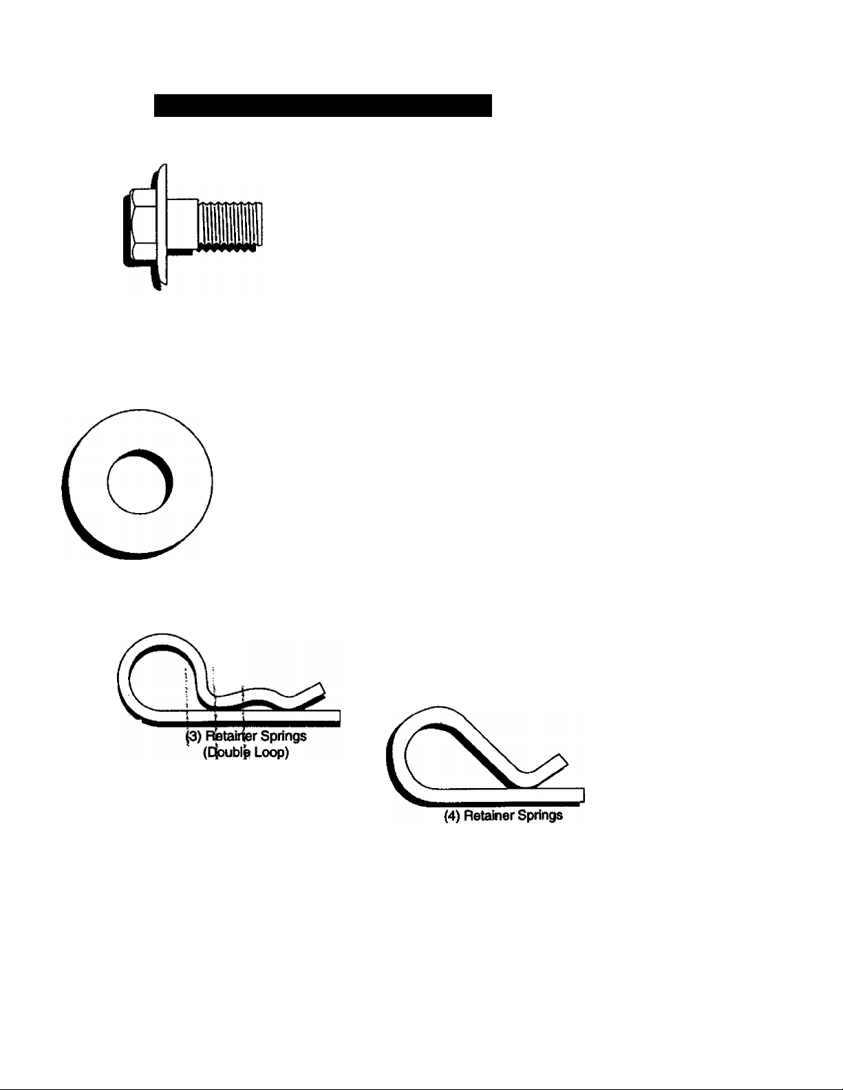
(1) Shoulder Bolt
5/16-18
(1) Knob
(1) Washer
17/32x1-3/16x12 Gauge
(Single Loop)
6
Page 7
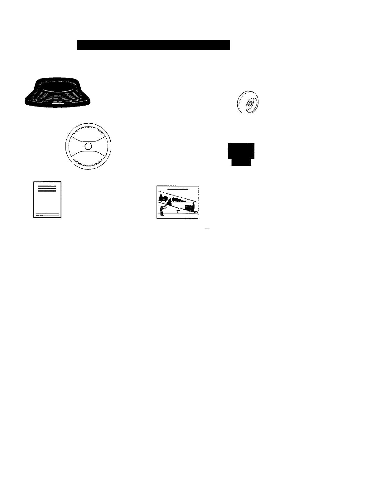
CONTENTS OF HARDWARE PACK
Parts packet separately in carton
□
Seat
Video
Cassette
Steering Wheel
Manual
Parts Bag
Parts Bag contents not shown full size
(2) Washers 3/8 ^
(2) Shoulder
Bolts
— (2) Centerlock (2) Gauge
(2)
I
Nuts Whoole
x7/8x14Ga. '
Wheels
O
Steering
Wheel Insert
Slope Sheet
^ =a
(2) Front Link Assemblies
Steering
Sleeve
Steering Sleeve
Extension
Page 8
ASSEMBLY
Your new tractor has been assembled at the factory with exception of those parts left
unassembled for shipping purposes. To ensure safe and proper operation of your tractor
all parts and hardware you assemble must be tightened securely. Use the correct tools
as necessary to insure proper tightness. Review the video cassette before you begin.
TOOLS REQUIRED FOR
ASSEMBLY
A socket wrench set will make assembly
easier. Standard wrench sizes you need
are listed below.
(1)9/16" wrench (1) 3/4" Socket w/
(1)1/2" wrench drive ratchet
(l)Pliers (1) Phillips Screw(1) Utility knife driver
(1) Tire pressure gauge
When right or left hand is mentioned in
this manual, it means, from your point of
view, when you are in the operating posi
tion (seated behind the steering wheel).
TO REMOVE TRACTOR FROM
CARTON
UNPACK CARTON
• Remove all accessible loose parts and
parts boxes from shipping carton (See
page 6).
• Cut, from top to bottom, along lines on
all four comers of shipping carton, and
lay panels flat.
• Remove mower and package materials.
• Check for any additional loose parts or
boxes and remove.
BEFORE ROLLING TRACTOR OFF
SKID
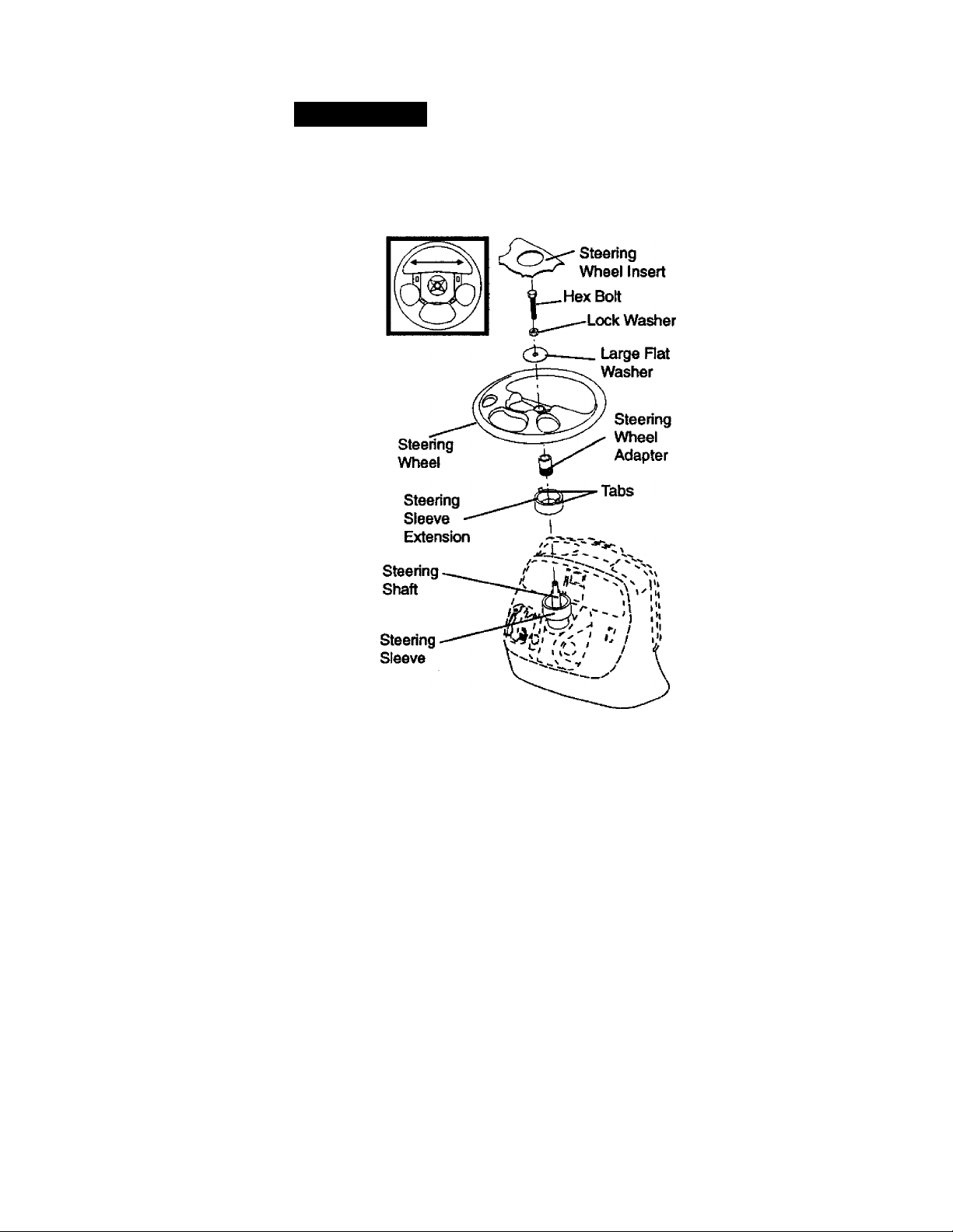
ATTACH STEERING WHEEL
• Remove hex bolt, lock washer and large
flat washer from steering shaft.
• Position front wheels of the tractor so
they are pointing straight fonvard.
• Slide ttie steering sleeve over the steer
ing shaft
• Align tabs and press steerirrg sleeve
extension into bottom of steering wheel.
• Position steering wheel so cross bars
are horizontal (left to right) and slide
onto steering wheel adapter.
• Secure steering wheel to steering shaft
with hex bolt, lock washer and large flat
washer previously removed. Tighten
securely.
• Snap steering wheel insert into center
of steering wheel.
IMPORTANT; Check for and remove any
staples in skid that may puncture tires
where tractor is to roll off skid.
TO ROLL TRACTOR OFF SKID (See
Operation section for iocation and
function of controls)
• Press lift lever plunger and raise attach
ment lift lever to its highest position.
• Release parking brake by depressing
clutch/brake pedal.
• Place freewheel control in freewheeling
position to disengage transmission (See
TO TRANSPORT in the Operation
section of this manual).
• Roll tractor forward off skid.
• Remove protective materials from trac
tor hood and grill.
Page 9
HOW TO SET UP YOUR TRACTOR
CHECK BATTERY
• Lift hood to raised position.
• If this battery is put into service after
month and year indicated on label (label
located between terminals) charge bat
tery for minimum of one hour at 6-10
amps. (See "BATTERY" in Maintenance
section of this manual for charging
instructions).
Ubet
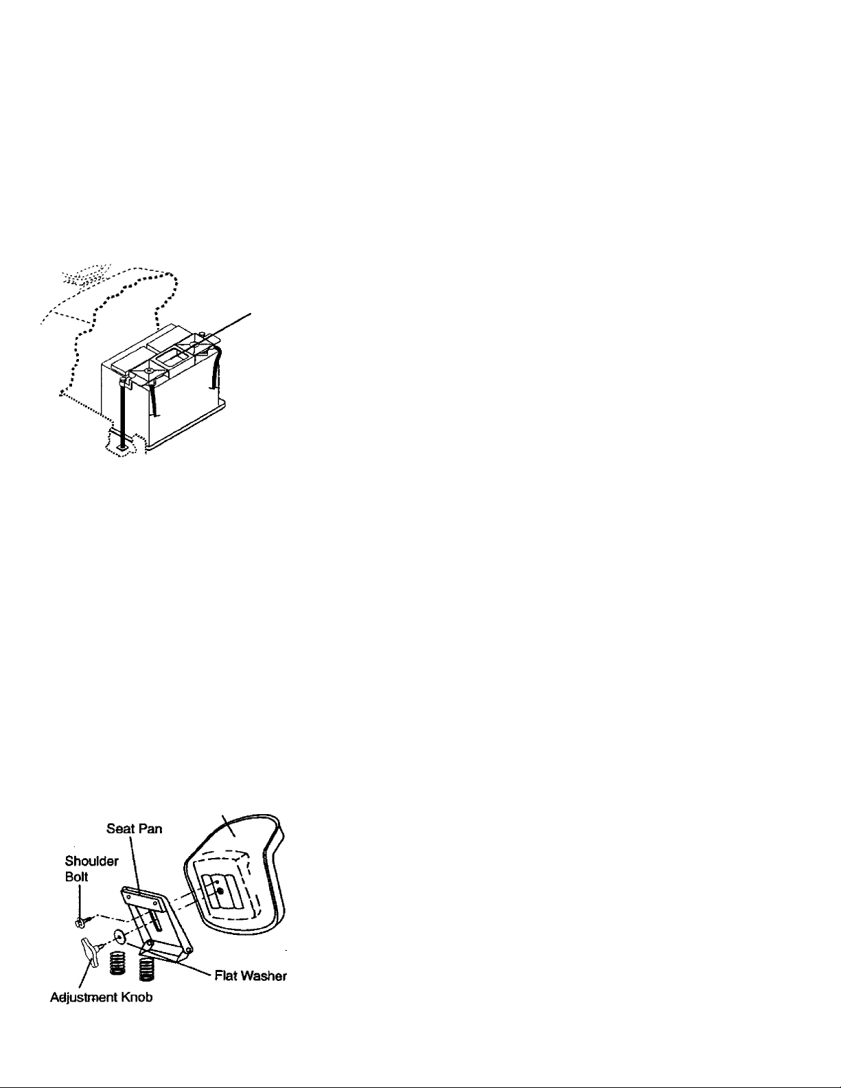
INSTALL SEAT
Adjust seat before tightening adjustment
knob.
• Remove cardboard packing on seat
pan.
• Place seat on seat pan and assemble
shoulder bolt. Tighten shoulder bolt
securely.
• Assemble adjustment knob and flat
washer loosely. Do not tighten.
• Lower seat into operating position and
sit on seat.
• Slide seat until a comfortable position is
reached which allows you to press
clutch/brake pedal all the way down.
• Get off seat without moving its adjusted
position.
• Raise seat and tighten adjustment knob
securely.
Seat
CHECK TIRE PRESSURE
The tires on your tractor were overinflated
at the factory for shipping purposes.
Correct tire pressure is important for best
cutting performance.
• Reduce tire pressure to PSI shown in
“PRODUCT SPECIFICATIONS" section
of this manual.
CHECK BRAKE SYSTEM
After you learn how to operate your trac
tor, check to see that the brake is properly
adjusted. See TO ADJUST BRAKE" in
the Service and Adjustments section of
this manual.
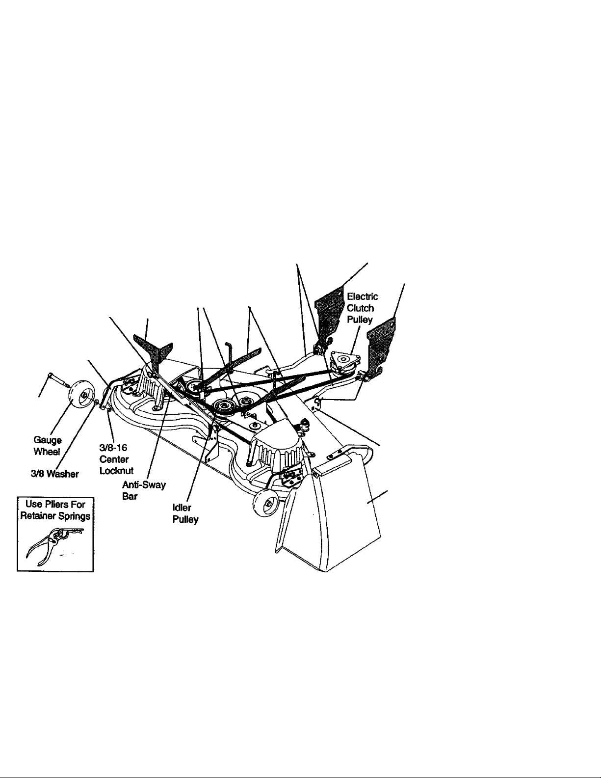
INSTALL MOWER AND DRIVE BELT
Be sure tractor is on level surface and
mower suspension arms are raised with
attachment lift control (see Know Your
Tractor in Operation section). Engage
parking brake.
• Cut and remove ties securing anti-sway
bar and belts. Swing anti-sway bar to
left side of mower deck.
• Slide mower under tractor with dis
charge guard to right side of tractor.
IMPORTANT: Check belt for prqper rout
ing in all mower pulley grooves. Install
belt into electric clutch pulley groove.
• Install one front link in top hole of the
left hand front mower bracket and left
hand front suspension bracket. Retain
with two single loop retainer springs as
shown.
• Install second front link in right hand
front suspension bracket and retain with
single loop retainer spring as shown.
• Slide right side of mower back and
install link in top hole of right hand front
mower bracket. Retain with single loop
retainer spring as shown.
• Turn height adjustment knob counter
clockwise until it stops.
• Lower mower linkage with attachment
lift control.
• Place the suspension arms on outward
pointing deck pins. If necessary, rock
and raise front of mower to align deck
pins with the holes in suspension arms.
Retain with double loop retainer springs
with loops down as shown.
• Connect anti-sway bar to chassis brack
et under left footrest and retain with
double loop retainer spring.
• Turn height adjustment knob clockwise
to remove slack from mower suspen
sion.
Page 10
• Raise deck to highest position.
• Assembie gauge wheeis as shown
using iong shouider boits, 3/8 washers,
and 3/8-16 center iocknuts. Tighten secureiy.
• Adjust gauge wheeis before operating
mower as shown in the Operation sec
tion of this manual.
CHECK MOWER LEVELNESS
For best cutting resuits, mower should be
property leveled. See “TO LEVEL
MOWER HOUSING" in the Service and
Adjustments section of this manual.
CHECK FOR PROPER POSITION OF
ALL BELTS
See the figures that are shown for replac
ing motion, mower drive, and mower blade
drive belts in the Service and Adjustments
section of this manual. Verify that the
belts are routed correctly.
Left Hand
Gauge
Wheel Bar
Shoulder
Bolt
Double Loop
Retainer Spring
Double Loop
Retainer Spring
(Inward pointing deck
pins) Suspension
Chassis ^ Arms
Bracket
Front
Links
Front
Suspension
Brackets
Single Loop
Retainer Springs
Front Mower
Bracket
Discharge
Guard
10
Page 11

CHECKLIST
Please review the following checklist:
/ All assembly instructions have been
completed.
/ No remaining loose parts in carton.
/ Battery is properly prepared and
charged. (Minimum 1 hour at 6 amps).
/ Seat is adjusted comfortably and tight
ened securely.
/ All tires are properly inflated. (For ship
ping purposes, the tires were overinflat
ed at the factory).
/ Be sure mower deck is properly leveled
side-to-side/front-to-rear for best cutting
results. (Tires must be properly inflated
for leveling).
/ Check mower and drive belts. Be sure
they are routed property around pulleys
and inside all belt keepers.
✓ Check wiring. See that all connections
are still secure and wires are property
clamped.
/ Before driving tractor, be sure freewheel
control is in drive position.
While learning how to use your tractor,
pay extra attention to the following impor
tant items:
✓ Engine oil is at proper level.
/ Fuel tank is filled with fresh, dean, regu
lar unleaded gasoline.
/ Become familiar with all controls - their
location and function. Operate them
before you start the engine.
✓ Be sure brake system is in safe operat
ing condition.
/ It is important to purge the transmission
before operating your tractor for the first
time. Follow proper starting and trans
mission purging instructions (See TO
START ENGINE” and “PURGE TRANS
MISSION” in the Operation section of
thisjmanual).
11
Page 12
OPERATION
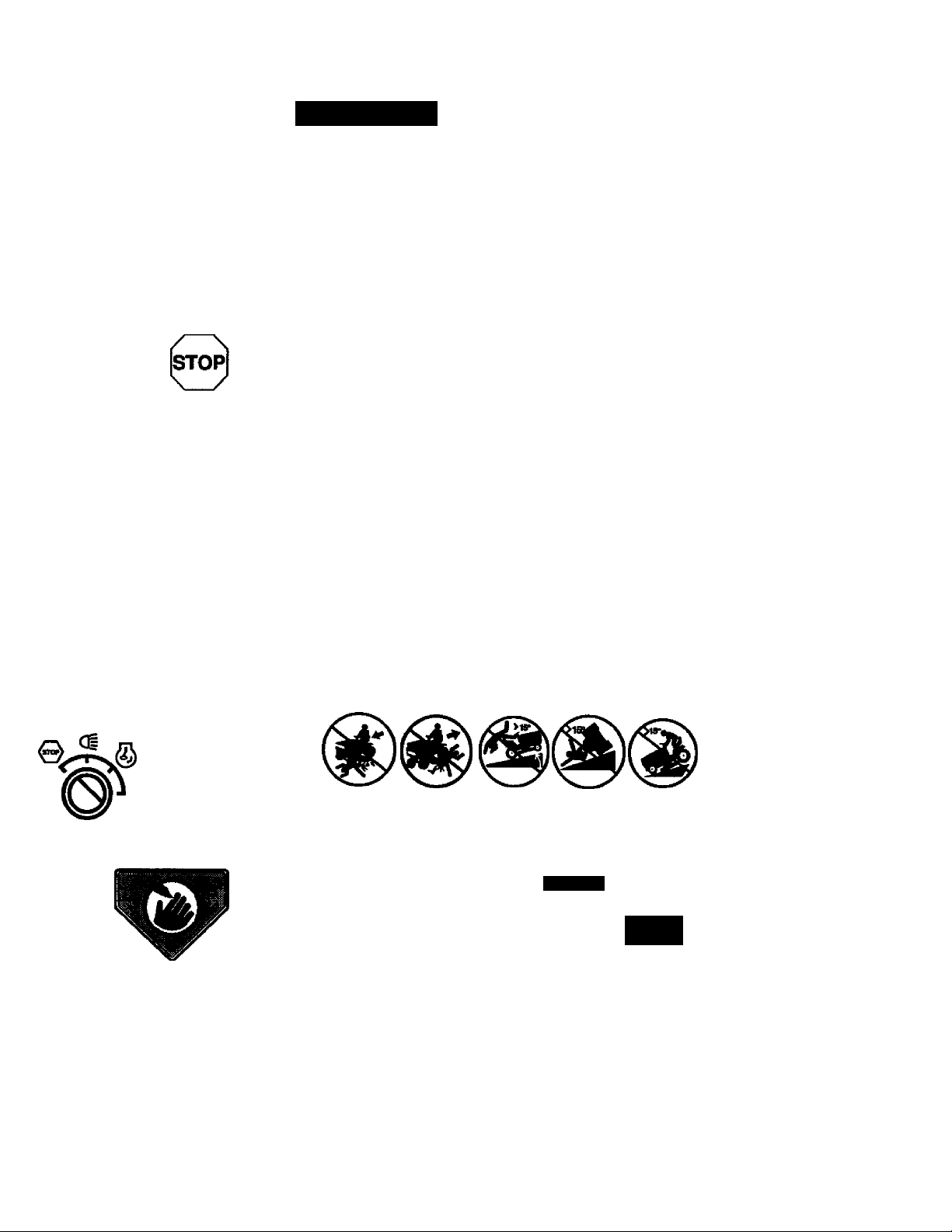
These symbols may appear on your tractor or in literature suppiied with the product.
Learn and understand their meaning.
Q A
BATTERY
WARNING
©
ENGINE ON
a
FUEL
i* R N H L
ATTACHMENT REVERSE
CLUTCH ENGAGED
a;
REVERSE
FORWARD
01
OIL PRESSURE
LIGHTS ON
ilf
MOWER HEIGHT
NEUTRAL HIGH
PARKING BRAKE
♦
©
LOCKED
OVER TEMP
UNLOCKED
LOW
FAST SLOW
©1
1L
LIGHT
I
Hi
MOWER UFT
PARKING BRAKE
ATTACHMENT
IGNITION
DANGER, KEEP HANDS AND FEET AWAY
CLUTCH DISENGAGED
KEEP AREA CLEAR SLOPE HAZARDS
(SEE SAFETY RULES SECTION)
- L_
i ^ »A
FREE WHEEL
(Automatic Models only)
12
Page 13
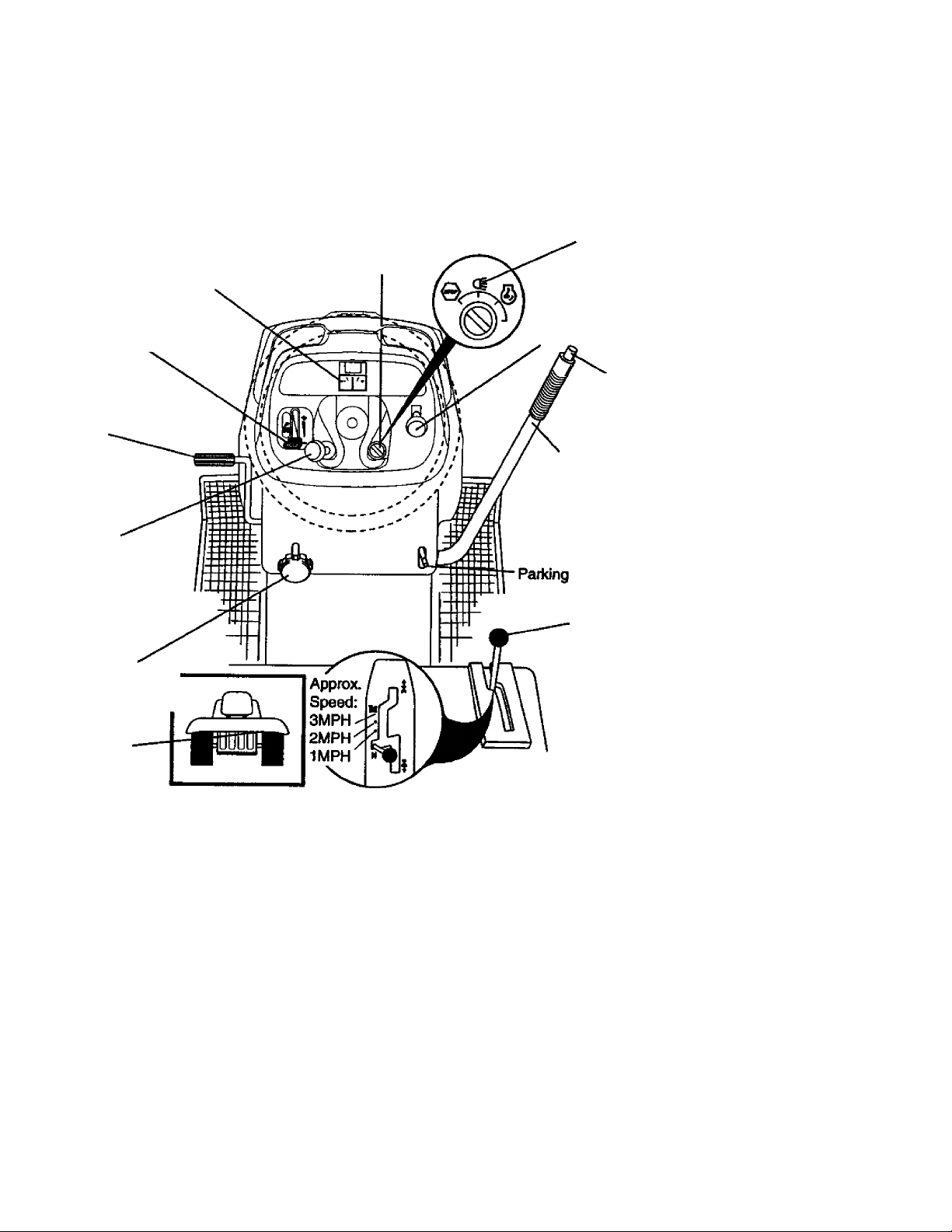
KNOW YOUR TRACTOR
READ THIS OWNER'S MANUAL AND SAFETY RULES BEFORE OPERATING YOUR
TRACTOR
Compare the illustrations with your tractor to familiarize yourself with the focations of
various controls and adjustments. Save this manual for future reference.
Light Switch
Ignition
Switch
Ammeter
Throttle Control
Clutch/Brake
Pedal
Choke
Control
Position
Attachment
Clutch Switch
Lift Lever
Plunger
Attachment
Lift Lever
Brake
Height
Adjustment
Knob
Free Wheel
Control
Our tractors conform to the safety standards of the American
National Standards Institute.
ATTACHMENT CLUTCH SWITCH: Used
to engage the mower blades, or other at
tachments mounted to your tractor.
LIGHT SWITCH: Turns the headlights on
and off.
THROTTLE CONTROL: Used to control
engine speed.
CLUTCWBRAKE PEDAL: Used for
declutching and braking the tractor and
starting the engine.
CHOKE CONTROL: Used when starting a
cold engine.
HEIGHT ADJUSTMENT KNOB: Used to
adjust the mower cutting height.
IGNITION-SWITCH: Used for starting and
stopping the engine.
Motion
Control
Lever
ATTACHMENT LIFT LEVER: Used to
raise and lower the mower deck or other
attachments mounted to your tractor.
LIFT LEVER PLUNGER: Used to release
attachment lift lever when changing its
position.
AMMETER: Indicates battery charging (+)
or discharging (-).
PARKING BRAKE: Locks clutch/brake
into the brake position.
MOTION CONTROL LEVER - Selects the
speed and direction of the tractor.
FREEWHEEL CONTROL - Disengages
transmission for pushing or slowly towing
the tractor with the engine off.
13
Page 14
The operation of any tractor can result in foreign objects thrown into the
eyes, which can result in severe eye damage. Always wear safety glasses
or eye shields while operating your tractor or performing any adjustments or
repairs. We recommend a wide vision safety mask over spectacles, or stan-
HOW TO USE YOUR TRACTOR
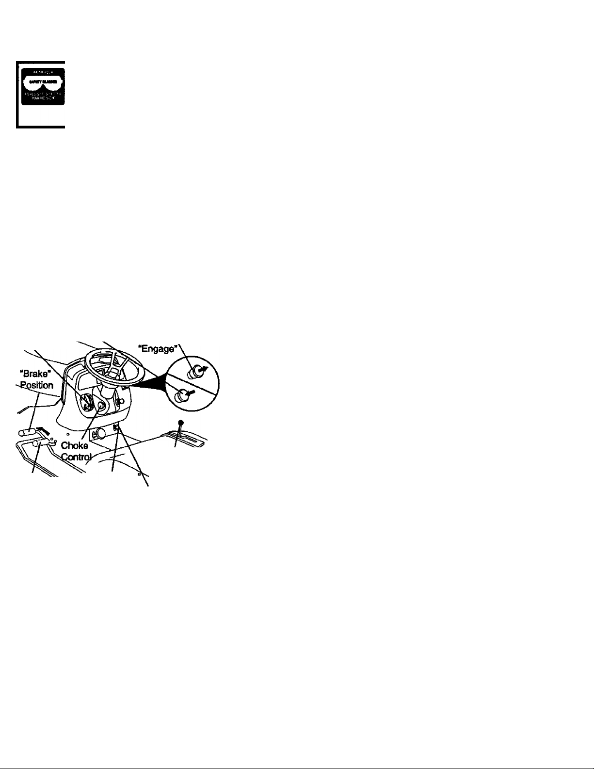
TO SET PARKING BRAKE
Your tractor is equipped with an operator
presence sensing switch. When engine
is running, any attempt by the operator to
leave the seat without first setting the
parking brake will shut off the engine.
• Depress clutch/brake pedal into full
“BRAKE” position and hold.
* Place parking brake lever in
“ENGAGED” position and release pres
sure from clutch/brake pedal. Pedal
should remain in “BRAKE” position.
Make sure parking brake will hold trac
tor secure.
Throttle
Control
Clutch/Brake
Pedal “Drive’
Position
Push-In to

• The average lawn should be cut to
approximately 2-1/2 inches during the
cool season and to over 3 inches during
hot months. For healthier and better
looking iawns, mow often and after
moderate growth.
• For best cutting performance, grass
over 6 inches in height should be
mowed twice. Make the first cut rela
tively high; the second to desired height.
TO ADJUST GAUGE WHEELS
Gauge wheeis are properly adjusted
when they are slightly off the ground when
mower is at the desired cutting height in
operating position. Gauge wheels then
keep the deck in proper position to help
prevent scalping in most terrain condi
tions.
• Adjust gauge wheels with tractor on a
flat level surface.
• Adjust mower to desired cutting height.
• Lower mower with lift control. Remove
rear retainer spring and clevis pin which
secure each gauge wheel.
• Lower gauge wheels to ground. Raise
gauge wheels slightly to align holes in
bracket and gauge wheel bar and insert
clevis pins. Gauge wheels should be
slightly off the ground.
• Replace retainer springs into clevis
pins.
Clevis Pin
Gauge
Wheels
Bar
Gauge
Wheel
Retrainer
Spring
Bracket
TO OPERATE MOWER
Your tractor is equipped with an operator
presence sensing switch. Any attempt by
the operator to leave the seat with the
engine running and the attachment clutch
engaged will shut off the engine.
• Select desired height of cut.
• Lower mower with attachment lift con
trol.
• Start mower blades by engaging attach
ment clutch control.
• TO STOP MOWER BLADES - disen
gage attachment clutch control.
A.CAUTION: Do not operate the mower
without either the entire grass catcher, on
mowers so equipped, or the discharge
guard in place.
Attachment Clutch
Switch Pull Out To
-Engage’
Push In To
“Disengage’
Attachment Lift Lever
High Position
Low
..^Position
K
_j! Discharge
\ Guard
TO OPERATE ON HILLS
iAkCAUTION; Do not drive up or down
hills with slopes greater than IS** and do
not drive across any slope. Use the slope
guide provided at the back of this manual.
• Choose the slowest speed before start
ing up or down hills.
• Avoid stopping or changing speed on
hills.
• If slowing is necessary, move throttle
control lever to slower position.
engage parking I
• Move motion controi iever to neutral (N)
position.
IMPORTANT: The motion control lever
does not return to neutral (N) position
when the clutch/brake pecral is depressed.
• To restart movement, slowiy release
parking brake and clutch/brake pedal.
• Slowly move motion controllever to
siowest setting.
• Make all turns slowly.
TO TRANSPORT
When pushing or towing your tractor, be
sure to disengage transmission by placing
freewheel control in freewheeiing posi
tion. Freewheel control is located at the
rear drawbar of tractor.
• Raise attachment lift to highest position
with attachment lift control.
• Remove retainer spring from freewheel
control rod.
• Push control rod in to disengage trans
mission and reinsert retainer spring into
control rod hole now on back side of the
bracket.
• Do not push or tow tractor at more than
two (2) MPH.
• To reengage transmission, reverse
above procedure.
15
Page 16

NOTE: To protect hood from damage
when transporting your tractor on a truck
or a trailer, be sure hood is closed and
secured to tractor. Use an appropriate
means of tying hood to tractor (rope, cord,
etc.).
' -/ti
4-iR
TOWING CARTS AND OTHER
ATTACHMENTS
Tow only the attachments that are recom
mended by and comply with specifications
of the manufacturer of your tractor. Use
common sense when towing. Too heavy of
a load, while on a slope, is dangerous.
Tires can lose traction with the ground and
cause you to lose control of your tractor.
BEFORE STARTING THE ENGINE
CHECK ENGINE OIL LEVEL
• The engine in your tractor has been
shipped, from the factory, already filled
with summer weight oil.
• Check engine oil with tractor on level
grourtd.
• Unthread and remove oil fill cap/dip;stick; wipe oil off. Reinsert the dipstick
into the tube and rest oil fill cap on the
tube. Do not thread the onto the
tube. Remove and read oil level. If nec
essary, add oil until “FULL” mark on
di{>stick is reached. Do not overfill.
• For cold weather operatiortyou should
dhange oil for easier starting (See “OIL
VISCOSITY CHART" in the Customer
Responsibilities section of this manual).
• To change engine oil, see the
Maintenance section in this manual.
ADD GASOLINE
• Rll fuel tank. Use fresh, clean, regular
unfeaded gasoline with a minimum of 87
octane. (Use of leaded gasoline will
increase carborf and lead oxide
deposits and reduce valve life). Do not
mix oil with gasoline. Purchaseiuel in
uantities that can be used within 30
Q
ays to assure fuel freshness.
IMPORTANT: When operating in tempera
tures below 32'’F(0“C), use fresh, clean
winter grade gasoline to help insure good
cold weather starting.
AwARNING; Experience indicates that
alcohol blended fuels (called gasohol or
using ethanol or methanol) can attract
moisture which leads to separation and
formation of acids during storage. Acidic
gas can damage the fuel system of an
engine while in storage. To avoid engine
problems, the fuel system should be emp
tied before storage of 30 days or longer.
Drain the gas tank, start the engine and let
it run until the fuel lines and carburetor are
empty. Use fresh fuel next season. See
Storage Instructions for additional
information. Never use engine or
carburetor cleaner products in the fuel
tank or permanent damage may occur.
AcaUTION: Rll to bottom of gas tank
filler neck. Do not overfill. Wipe off any
spilled oil or fuel. Do not store, spill or use
gasoline near an open flame.
TO START ENGINE
When starting the engine for the first time
or if the engine has run out of fuel, it will
take extra cranking time to move fuel from
the tank to the engine.
• Be sure freewheel control is in the
transmission engaged position.
• Sit on seat in operating position,
depress clutchAjrake pedal and set
paridng brake.
• Place motion control lever in neutral (N)
position.
• Move attachment clutch to “DISEN
GAGED” position.
• Move throttle control to fast position
• Pull choke control out for a cold engine
start attempt. For a warm engine start
attempt the choke control may not be
needed.
NOTE: Before starting, read the warm and
cold starting procedures below.
• Insert key into ignition and turn key
clockwise to “START position and
release key as soon as engine starts.
Do not run starter continuously for more
than fifteen seconds per minute. If the
engine does not start after several
attempts, push choke control in, wait a
few minutes and try again. If engine still
does not start, pull the choke control out
and retry.
16
Page 17

WARM WEATHER STARTING (50“ F
AND ABOVE)
• When engine starts, slowly push choke
control in until the engine begins to run
smoothly. If the engine starts to run
roughly, puli the choke control out slight
ly for a few seconds and then continue
to push the control in slowly.
• The attachments and ground drive can
now be used. If the engine does not
accept the load, restart the engine and
allow it to warm up for one minute using
the choke as described above.
COLD WEATHER STARTING (50“ F AND
BELOW)
• When engine starts, slowly push choke
control in until the engine begins to run
smoothly. Continue to push the choke
control in small steps allowing the
engine to accept small changes in
speed and load, until the choke control
is fully in. If the engine starts to run
roughly, pull the choke control out slight
ly for a few seconds and then continue
to push the control in slowly. This may
require an engine warm-up period from
several seconds to several minutes,
depending on the temperature.
AUTOMATIC TRANSMISSION WARM-UP
• Before driving the unit in cold weather,
the transmission should be warmed up
as follows:
• Be sure the tractor is on level ground.
• Place the motion control lever in neu
tral. Release the parking brake and
let the clutch/brake slowly return to
operating position.
• Allow one minute for transmission to
warm up. This can be done during the
engine warm up period.
• The attachments can be used during
the engine warm-up period after the
transmission has been warmed up and
may require the choke control be pulled
out slightly.
NOTE: A high altitude (above 3000 feet)
or in cold temperatures (below 32 F) the
carburetor fuel mixture may need to be
adjusted for best engine performance.
See TO ADJUST CARBURETOR” in the
Service and Adjustments section of this
manual.
PURGE TRANSMISSION
i^CAUTION: Never engage or disen
gage freewheel lever while the engine is
running.
To ensure proper operation and perfor
mance, it is recommended that the trans
mission be purged before operating tractor
for the first time. This procedure will
remove any trapped air inside the trans
mission which may have developed during
shipping of your tractor.
IMPORTANT: Should your transmission
require removal for service or replace
ment, it should be purged after reinstalla
tion before operating the tractor.
• Place tractor safely on level surface with
engine off and parking brake set.
• Disengage transmission by placing free
wheel control in freewheeling position
(See TO TRANSPORT tn this section
of manual).
• Sitting in the tractor seat, start engine.
After the engine is running, move throt
tle control to slow position. With motion
control lever in neutral (N) position,
slowly disengage clutch/brake pedal.
• Move motion control lever to full fonvard
osition and hold for five (5) seconds,
R
love lever to full reverse position and
hold for five (5) seconds. Repeat this
procedure three (3) times.
NOTE: During this procedure there will be
no movement of drive wheels. The air is
being removed from hydraulic drive sys
tem.
• Move motion control lever to neutral (N)
position. Shut off engine and set parking
brake.
• Engage transmission by placing free
wheel control in driving position (See
TO TRANSPORT in this section of
manual).
• Sitting in the tractor seat, start engine.
After the engine is running, move throt
tle control to half (1/2) ^ed. With
motion control lever in neutral (N) posi
tion, slowly disengage clutch/brake
pedal.
• Slowly move motion control lever for
ward; after the tractor moves approxi
mately five (5) feet, slowly move motion
control lever to reverse position. After
the tractor moves approximately five (5)
feet return the motion control lever to
the neutral (N) position. Repeat this pro
cedure with the motion control lever
three (3) times.
* Your tractor is now purged and now
ready for normal operation.
17
Page 18

MOWING TIPS
• Tire chains cannot be used when the
mower housing is attached to tractor.
• Mower should be properly leveled for
best mowing performance. See TO
LEVEL MOWER HOUSING” in the
Service and Adjustments section of this
manual.
• Use the runner on the right hand side of
mower as a guide. The blade cuts
approximately an inch outside the run
ner (See fig. X)
• The left hand side of mower should be
used for trimming.
• Drive so that clippings are discharged
onto the area that has been cut. Have
the cut area to the right of the tractor.
This will result in a more even distribu
tion of clippings and more uniform cut
ting.
• When mowing large areas, start by turn
ing to the right so that clippings will dis
charge away from shrubs, fences, drive
ways, etc. After one or two rounds, mow
in the opposite direction making left
hand turns until finished.
• If grass is extremely tall, it should be
mowed twice to reduce load and possi
ble fire hazard from dried clippings.
Make first cut relatively high; the second
to the desired height.
• Do not mow grass when it is wet. Wet
grass will plug mower and leave unde
sirable clumps. Allow grass to dry
before mowing.
• Always operate engine at full throttle
when mowing to assure better mowing
performance and proper discharge of
material. Regulate ground speed by se
lecting a low enough gear to give the
mower the best cutting performance as
well as the quality of cut desired.
• When operating attachments, select a
ground speed that will suit the terrain
and give best performance of the at
tachment being used.
18
Page 19

CUSTOMER RESPONSIBILITIES
MAINTENANCE SCHEDULE
FlU IN DATES
AS YOU COMPLETE
MAINTENANCE
Check Brake Operation
Check Tire Pressure
Check Operator Presence and
Interiock Systems
Check for Loose Fasteners
Sharpen/Reptг№e Mower Blades
Lubiicatton Chart
Check Battery Level
Clean Battery and Termkials
Check Transaxle Cooling
Adjust Blade Belt(s) Tension
Adjust Motion Drive Belt(s) Tension
Check En^ne Oil Level
Change Engine Oil
Clean Air RIter
Clean Air Screen
Inspect Muffler/Spark Arrester
Replace OI RIter (If eguipped)
Clean Engine Cooling Fins
Replace Spark Plug
Replace ^r RIter Paper Cartridge
Replace Fuel Filter
1 • Chang* tnon olían whan opatafog unJar a haavy load or In high tanUanl tan^aialu**.
2 • Saivico men oHan whan oparatkig h dirty or dusty condhlDni.
3 • II aquippad wlh oi Шаг, Chang* on avaiy 50 hours.
4 - Rapine* blade» tnon dlan when mowkig h sandy sol.
GENERAL RECOMMENDATIONS
The warranty on this tractor does not cover
items that have been subjected to operator
abuse or negligence. To receive full value
from the warranty, operator must maintain
tractor as instructed in this manual. Some
adjustments will need to be made periodi
cally to properly maintain your tractor.
Ail adjustments in the Service and
Adjustments section of this manual should
be checked at least once each season.
• Once a year you should replace the
✓ ✓
✓
✓
✓
✓
✓
✓ a
✓
✓ *
✓
✓
✓
✓ 2
✓ 2
9Spindle Zerk
©Front
Wheel
Bearing
Zerk
©Steering
Sector
Gear Teeth
✓ t
✓ s
✓ 5
✓
✓ 2
✓
✓ 2
5 - H equipad wWi ad)uslabl* systam.
6 - Mol tsquhad I equipad wth makilanancalina baBaty.
7 • Tiritan Irani ada pivot ho* 10 35 II.Иbs. maximum.
✓
✓
✓
✓
✓
!✓ 1
Do not ovarUghtan.
LUBRICATION CHART
OTIe Rod Ball Joints
©Spindle Zerk
©Front
Wheel
Bearing
Zerk
©Engine
spark plug, clean or replace air filter, and
check blades and belts for wear. A new
spark plug and clean air filter assure
proper air-fuel mixture and help your
engine run better and last longer.
BEFORE EACH USE
• Check engine oil level.
©Spray Silicone tubriant (Move Boots to Lubricate)
©General Purpose Grease
©Refer to Maintenance “ENGINE" Section
• Check brake operation.
Check tire pressure.
Check operator presence and interlock ''''hich have special nylon bearings. Viscous lubrisystems for proper operation cants will attract dust and dirt that will shorten the
Check-for loose fasteners. ’ 'i i*® fe'^ubricating bearings. If you feel they
uic IMPORTANT: Do not oil or greeise the pivot points
must be Jubneated, use only a dry, powdered
graphite type lubricant sparingly.
19
Page 20
TRACTOR
Always observe safety rules when per
forming any maintenance.
BRAKE OPERATION
if tractor requires more than six (6) feet
stopping distance at high speed in highest
gear, then brake must be adjusted. (See
“TO ADJUST BRAKE” in the Service and
Adjustments section of this manual).
TIRES
• Maintain proper air pressure in all tires
(See “PRODUCT SPECIFICATIONS”
section of this manual).
• Keep tires free of gasoline, oil, or insect
control chemicals which can harm rub
ber.
• Avoid stumps, stones, deep ruts, sharp
objects and other hazards that may
cause tire damage.
NOTE: To seal tire punctures and prevent
flat tires due to slow leaks, tire sealant
may be purchased from your local parts
dealer. Tire sealant also prevents tire dry
rot and corrosion.
OPERATOR PRESENCE SYSTEM
Be sure operator presence and interlock
systems are working properly. If your trac
tor does not function as described below,
repair the problem immediately.
• The engine should not start unless the
clutch/brake pedal is fully depressed
and attachment clutch control is in the
disengaged position.
• When the engine is running, any
attempt by the operator to leave the
seat without first setting the parking
brake should shut off the engine.
• When the engine is running and the
attachment clutch is engaged, any
attempt by the operator to leave the
seat should shut off the engine.
• The attachment clutch should never
operate'unless the operator is in the
seat.
BLADE CARE
For best results mower blades must be
kept sharp. Replace bent or darhaged
blades.
BLADE REMOVAL
• Raise mower to highest position to allow
access to blades.
• Remove hex bolt, lock washer and flat
washer securing blade.
• Install new or resharpened blade with
trailing edge up towards deck as shown.
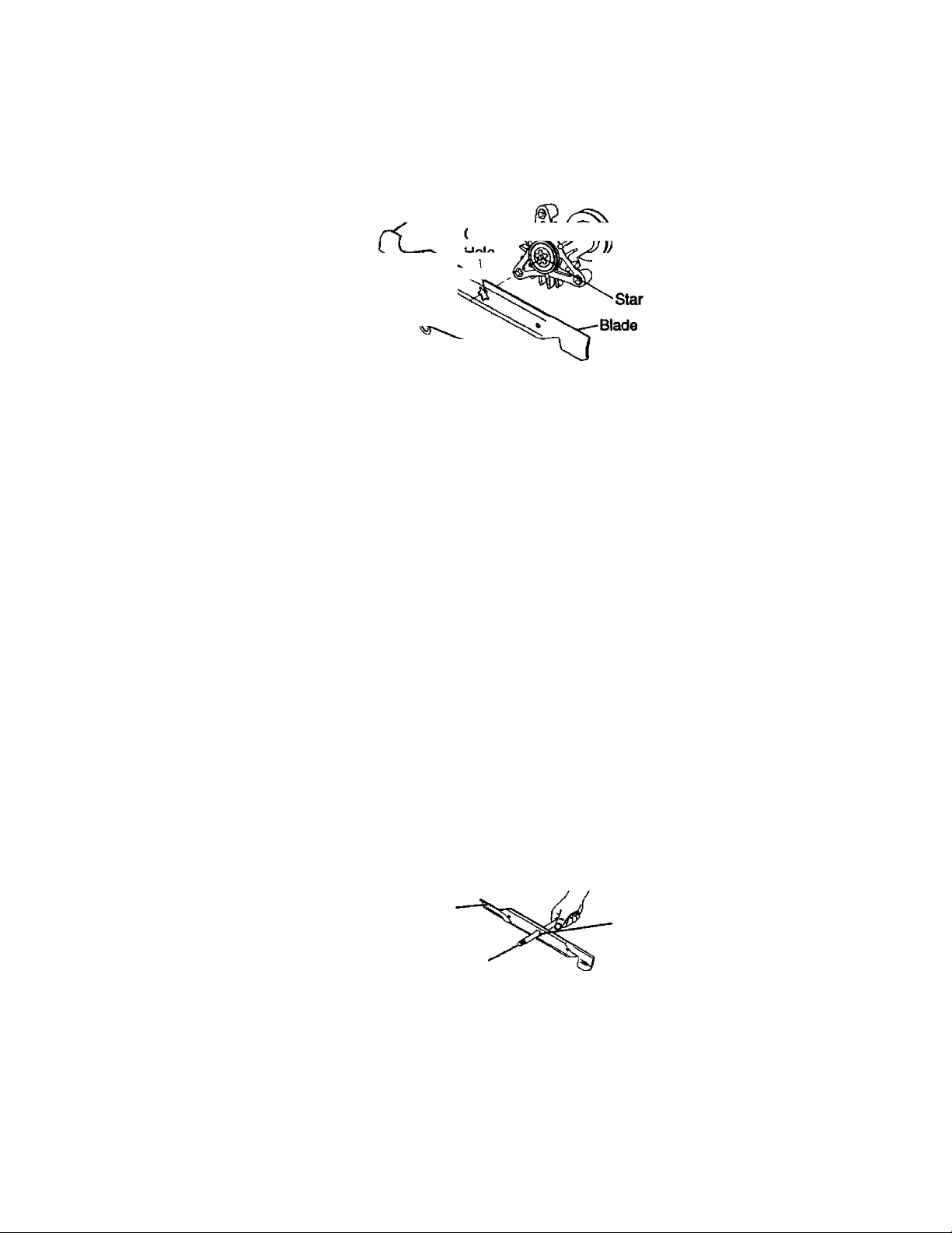
IMPORTANT: To ensure proper assembly,
center hole in blade must align with star
on mandrel assembly.
• Reassemble hex bolt, lock washer and
flat washer in exact order as shown.
• Tighten bolt securely (27-35 Ft. Lbs.
torque).
IMPORTANT: Blade bolt is Grade 8 heat
treated.
Trail tng^ edge up
'enter ,
I iwio Mandrel
WasherN^:^^^
Hex Bolt
(Grade
Lock Washer
*A Grade 8 heat treated bcdt can be
identified by six lines on the bolt head.
Assembly
TO SHARPEN BLADE
NOTE: We do not recommend sharpening
blade, but if you do, be sure the blade is
balanced.
Care should be taken to keep the blade
balanced. An unbalanced blade will cause
excessive vibration and eventual damage
to mower and engine.
• The blade can be sharpened with a file
or on a grinding wheel. Do not attempt
to sharpen while it is on the mower.
• To check blade balance, you will need a
5/8” diameter steel bolt, pin, or a cone
balancer. (When using a cone balancer,
follow the instructions suppiied with bal
ancer).
NOTE: Do not use a nail for balancing
blade. The lobes of the center hole may
appear to be centered, but are not.
• Slide blade onto an unthreaded portion
of the steel bolt or pin and hold the bolt
or pin parallel with the ground. If blade
is balanced, it should remain in a hori
zontal position. If either end of the blade
moves downward, sharpen the heavy
end until the blade Is balanced.
Blade
5/8“ Bolt or Pin
Center Hole
BATTERY
Your tractor has a battery charging system
which is sufficient for normal use.
However, periodic charging of the battery
with an automotive charger will extend its
life.
• Keep battery and terminals clean.
• Keep battery bolts tight.
• Keep small vent holes open.
• Recharge at 6-10 amperes for 1 hour.
20
Page 21
NOTE: The original equipment battery on
your tractor is maintenance free. Do not
attempt to open or remove caps or covers.
Adding or checking level of electrolyte is
not necessary.
TO CLEAN BATTERY AND TERMINALS
Corrosion and dirt on the battery and ter
minals can cause the battery to “leak"
power.
• Remove terminal guard.
• Disconnect BLACK battery cable first
then RED battery cable and remove
battery from tractor.
• Rinse the battery with plain water and
dry.
• Clean terminals and battery cable ends
with wire brush until bright.
• Coat terminals with grease or petroleum
jelly.
• Reinstall battery (See “REPLACING
BATTERY" in the SERVICE AND
ADJUSTMENTS section of this manu
al).
V-BELTS
Check V-belts for deterioration and wear
after 100 hours of operation and replace if
necessary. The belts are not adjustable.
Replace belts if they begin to slip from
wear. ■
TRANSAXLE COOLING '
The transmission fan and cooling fins
should be kept clean to assure proper
cooling.
Do not attempt to clean fan or transmis
sion while engine is running or while the
transmission is hot.
• Inspect cooling fan to be sure fan
blades are intact and clean.
• Inspect cooling fins for dirt, grass clip
pings and other materials. To prevent
damage to seals, do not use com
pressed air or high pressure sprayer to
clean cooling fins.
TRANSAXLE PUMP FLUIG
The transaxle was sealed at the factory
and fluid maintenance is not required for
the life of the transaxle. Should the
transaxle ever leak or require servicing,
contact your nearest authorized service
center/department.
ENGINE
LUBRICATION
Only use high quality detergent oil rated
with API service classification SF, SG, or
SH_ Select the oil’s SAE viscosity grade
according to your exjDected operating tem
perature.
SAE VISOOSnY GRADES
SO* K* 4Cr
TEMPERATURE RANGE ANTIdPATEP BEFORE NEXT O fL CHANGE
Change the oil after every 50 hours of
operation or at least once a year if the
tractor is not used for 50 hours in one
year.
Check the crankcase oil level before start
ing the engine and after each eight (8)
hours of operation. Tighten oil fill cap/dipstick securely each time you check the oil
level.
TO CHANGE ENGINE OIL
Determine temperature range expected
before oil change. All oil must meet API
service classification SF, SG, or SH.
• Be sure tractor is on level surface.
• Oil will drain more freely when warm.
• Catch oil in a suitable container.
• Remove oil fill cap/dipstick. Be careful
not to allow dirt to enter the engine
when changing oil.
• Remove drain plug.
• After oil has drained completeiy, replace
oil drain plug and tighten securely.
• Refill engine with oil through oil fill dip
stick tube. Pour slowly. Do not overfill.
For approximate capacity see “PROD
UCT SPECIFICATIONS” section of this
manual.
• Use gauge on oil fill cap/dipstick for
checldng level. Insert dipstick into the
tube and rest the oil fill cap on the tube.
Do not thread the cap onto the tube
when taking reading. Keep oil at
“FULL” line on dipstick. Tighten cap
onto the tube securely when finished.
Oil Drain
Oil RII
Cap/DIpstick
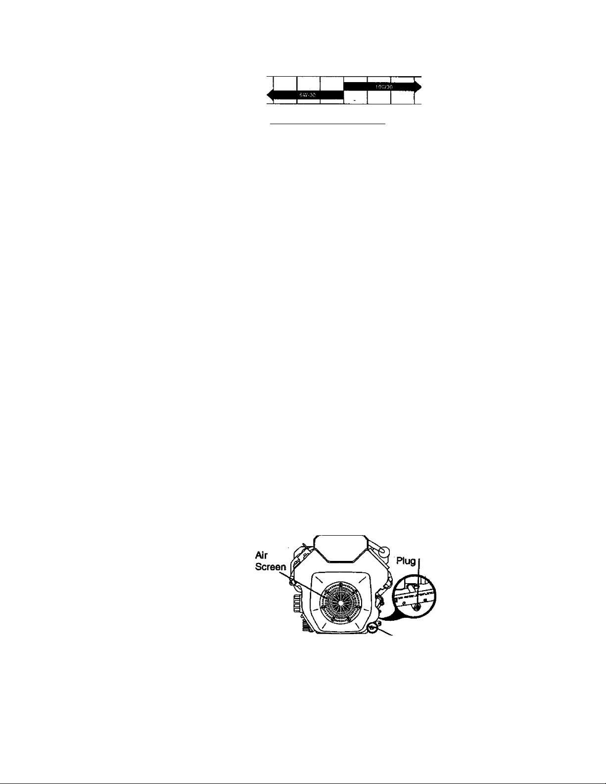
CLEAN AIR SCREEN
Air screen must be kept free of dirt and
chaff to prevent engine damage from over
heating. Clean with a wire brush or com
pressed air to remove dirt and stubborn
dried gum fibers.
21
Page 22

CLEAN AIR INTAKE/COOLING AREAS
To insure proper cooling, make sure the
grass screen, cooling fins, and other
external surfaces of the engine are kept
clean at all times.
Every 100 hours of operation (more often
under extremely dusty, dirty conditions),
remove the blower housing and other
cooling shrouds. Clean the cooling fins
and external surfaces as necessary. Make
sure the cooling shrouds are reinstalled.
NOTE: Operating the engine with a
blocked grass screen, dirty or plugged
cooling fins, and/or cooling shrouds re
moved will cause engine damage due to
overheating.
AIR FILTER
Your engine will not run property using a
dirty air filter. Clean the foam pre-cleaner
after every 25 hours of operation or every
season. Service paper cartridge every
100 hours of operation or every season,
whichever occurs first.
Service air cleaner more often under dusty
conditions.
• Loosen knob and remove cover.
TO SERVICE PRE-CLEANER
• Slide foam pre-cleaner off cartridge.
• Wash it in liquid detergent and water.
• Squeeze it dry in a clean cloth. Allow it
to dry.
• Saturate it in engine oil. Wrap it in
clean, absorbent cloth and squeeze to
remove excess oil.
TO SERVICE CARTRIDGE
• Replace a dirty, bent, or damaged car
tridge.
proper position around stud. Replace if
necessary.
• Reassemble air cleaner, cartridge plate,
and nut.
• Reinstall air cleaner cover and secure
by tightening knob.
ENGINE OIL FILTER
Replace the engine oil filter every season
or with every second oil change if the trac
tor is used more than 100 hours in one
year.
MUFFLER
Inspect and replace corroded muffler and
spark arrester (if equipped) as it could cre
ate a fire hazard and/or damage.
SPARK PLUGS
Replace spark plugs at the beginning of
each mowing season or after every 100
hours of operation, whichever occurs first.
Spark plug type and gap setting are
shown in “PRODUCT SPECIFICATIONS"
section of this manual.
IN-LINE FUEL FILTER
The fuel filter should be replaced once
each season. If fuel filter becomes
clogged, obstructing fuel flow to carbure
tor, replacement is required.
• With engine cool, remove filter and plug
fuel line sections.
• Place new fuel filter in position in fuel
line with arrow pointing towards carbu
retor.
• Be sure there are no fuel line leaks and
clamps are property positioned.
• immediately wipe up any spilled gaso
line.
Clamp
Clamp
Foam
Pre-cleaner
Cartridge Plate
Cartridge
Rubber
Seal
NOTE: Do not wash the paper cartridge
or use pressurized air, as this will damage
the cartridge.
• Remove nut and cartridge plate.
• Reinistall the pre-cleaner (cleaned and
oiled) over the paper cartridge.
• Check rubber seal for damage and
Fuel Filter
CLEANING
• Clean engine, battery, seat, finish, etc.
of all foreign matter.
• Keep finished surfaces and wheels free
of all gasoline, oil, etc.
• Protect painted surfaces with automo
tive type wax.
We do not recommend using a garden
hose to clean your tractor unless the elec
trical system, muffler, air filter and carbure
tor are covered to keep water out. Water
in engine can result in a shortened engine
life.
22
Page 23

SERVICE AND ADJUSTMENTS
AcAUTION; Before [
• Depress clutch/brake pedal fully and set paiidng brake.
• Place motion control lever in neutral (N) position.
• Place attachment clutch in “DISENGAGED” position.
• Turn ignition key “OFP and remove key.
• Make sure the blades and all moving parts have completely stopped.
• Disconnect spark plug wire from spark plug and place wire where it cannot come
in contact with plug.
TRACTOR
TO REMOVE MOWER
• Place attachment clutch in “DISEN
GAGED” position.
• Turn height adjustment knob to lowest
setting.
• Lower mower to its lowest position.
• Remove retainer spring holding anti-
swaybar to chassis bracket and disen
gage anti-swaybar from bracket.
• Remove retainer springs from suspen
sion arms at deck and disengage arms
from deck.
• Raise attachment lift to its highest posi
tion.
performing any sen/ice or adjustments:
ke pedal fully i . - . .
• Remove two retainer springs from each
front link and remove links.
• Slide mower fonvard and remove belt
from electric clutch pulley.
• Slide mower out from under right side of
tractor.
IMPORTANT: If an attachment other than
the mower deck is to be mounted on the
tractor, remove the front links.
TO INSTALL MOWER
Follow procedure described in “INSTALL
MOWER AND DRIVE BELr in the
Assembly section of this manual.
Page 24

TO LEVEL MOWER HOUSING
Adjust the mower while tractor is parked
on level ground or driveway. Make sure
tires are properly inflated (See “PROD
UCT SPECIFICATIONS”). If tires are
over or underinflated, you will not properly
adjust your mower.
SIDE-TO-SIDE ADJUSTMENT
• Raise mower to its highest position.
• Measure height from bottom of deck
curl to ground level at front comers of
mower. Distance “A” on both sides of
mower should be the same.
• If adjustment is necessary, make adjust
ment on one side of mower only.
• To raise one side of mower, tighten lift
link adjustment nut on that side.
• To lower one side of mower, loosen lift
link adjustment nut on that side.
NOTE: Each full turn of adjustment nut
will change mower height about 3/16".
• Recheck measurements after adjusting.
• To raise front of mower housing, loosen
nut “H" from trunnion on both front links.
Tighten nut “G” on both front links an
equal number of turns. .
• When distance “P is 1/8" to 1/2" lower
at front than rear, tighten nut “H”
against trunnion on both front links.
NOTE: Each full turn of nut “G” will
change dim. “P by approximately 3/8“.
• Recheck side-to-side adjustment.
Mandrel
Both Front Unks Should be Equal in Length
FRONT-TO-BACK ADJUSTMENT
IMPORTANT: Deck must be level side-to-
side. If the following front-to-back adjust
ment is necessary, be sure to adjust both
front links equally so mower will stay level
side-to-side.
To obtain the best cutting results, the
mower housing should be adjusted so the
front is approximately 1/8" to 1/2" lower
than the rear when the mower is in its
highest position.
Check acjjustment on right side of tractor.
Measure distance “P directly in front of
and behind the mandrel at bottom edge of
mower housing as shovwi.
• Before making any necessary adjust
ments, check that both front finks are
equal in length.
• If links are not equal in length, adjust
one link to same length as other link.
• To lower front of mower housing, loosen
nut “G” on both front links an equal
number of turns.
• When distance “P is 1/8" to 1/2* lower
at front than rear, tighten nut “H” against
trunnion on both front links.
Nut"H
Trunnion
Front
Nut “G"
Trunnion
TO REPLACE MOWER DRIVE BELT
MOWER DRIVE BELT REMOVAL
• Park tractor on a level surface. Engage
parking brake.
• Remove screws from left hand mandrel
cover and remove cover.
• Roll belt over the top of left hand man
drel pulley.
• Remove belt from electric clutch pulley.
• Remove belt from idler pulleys.
• Remove any dirt or grass dippings
which may have accumulated around
mandrels and entire upper deck sur
face.
• Check primary idler arm and two idlers
to see that they rotate freely.
• Be sure spring is securely hooked to pri
mary idler arm and bolt in mower hous
ing.
24
Page 25

MOWER DRIVE BELT INSTALLATION
• Install belt in both idlers. Make sure belt
is in both belt keepers at the idlers as
shown.
• Install new belt onto electric clutch pul
ley.
Screws
Roll belt into upper groove of left hand
mandrel pulley.
Carefully check belt routing making sure
belt is in the grooves correctly and
inside belt keepers.
Reassemble left hand mandrel cover.
Left Hand
Mandrel
Cover
Left Hand
Mandrel
Mower
Drive Belt
Electric
Belt
Keepers
TO REPLACE MOWER BLADE DRIVE
BELT
Park the tractor on level surface. Engage
parking brake.
• Remove mower drive belt (See TO
REPLACE MOWER DRIVE BELT in
this section of this manual).
• Remove mower (See TO REMOVE
MOWER” in this section of this manual).
• Remove screws from right hand man
drel cover and remove cover. Unhook
spring from bolt on mower housing.
• Carefully roll belt off right hand mandrel
julley.
• Remove belt from center mandrel pul-
ey, idler pulley, and left hand mandrel
pulley.
• Remove any dirt or grass which may
have accumulated around mandrels and
entire upper deck surface.
Check secondary idler arm and idler to
see that they rotate freely.
Be sure spring is hooked in secondary
idler arm and sway-bar bracket.
Install new belt in lower groove of left
hand mandrel pulley, idler pulley, and
center mandrel pull^ as shown.
Roil belt over right hand mandrel pulley.
Make sure belt is in all grooves properly.
Reconnect spring to bolt in mower
housing and reinstall right hand mandrel
cover.
Reinstall mower to tractor (See
“INSTALL MOWER AND DRIVE BELT
in the Assembiy section of this manual).
Reassemble mower drive belt (See TO
REPLACE MOWER DRIVE BELT in
this section of this manual).
25
Page 26

Left Hand
Mandrel
Secondary.
Idler Arm
Mower Blade
Drive Belt
Center
Mandrel
Right Haixl
Mandrel
Cover
Anit-Sway Bar
Bracket
TO ADJUST ATTACHMENT CLUTCH
The electric clutch should provide years of
service. The clutch has a built-in brake
that stops the puiley within 5 seconds.
Eventually, the Internal brake will wear
which may cause the mower blades to not
engage, or, to not stop as required.
Adjustments should be made by your
nearest authorized sen/ice center/department.
• Make sure attachment clutch and igni
tion switches are in “OFF position.
• Adjust №e three nylon locknuts until
space between clutch plate and rotor
measures .012" at all three slot loca
tions cut in the side of brake plate.
Idler
Pulley
Road test tractor for proper stopping
distance as stated above. Readjust if
necessary. If stopping distance is still
greater than six (6) feet in highest gear,
further maintenance is necessary.
Contact your nearest authorized ser
vice center/department.
With Parking Brake “Engaged"
NOTE: After installing a new electric
clutch, run tractor at full throttle and
engage and disengage electric clutch 10
cycles to wear in clutch plate._
TO ADJUST BRAKE
Your tractor is equipped with an adjustable
brake system which is mounted on №e
side of the transaxle.
If tractor requires more than six {6) feet
stopping distance at high speed in high
est gear, then brake must be adjusted.
• Depress clutch/brake pedal and engage
parking brake.
• Measure distance between brake oper
ating arm and nut "A” on brake rod.
• If distance is other than 1-1/2", loosen
jammut and turn nut "A” until distance
becomes 1-1/2". Retighten jam nut
: against nut “A”.
TO REPLACE MOTION DRIVE BELT
Park the tractor on level surface. Engage
parking brake. For ease of service there
IS a belt installation guide decal on bottom
of left footrest.
• Remove mower (See TO REMOVE
MOWER" in this section of this manual.)
BELT REMOVAL-
• Engage parking brake (creates slack in
belt).
• Remove belt from clutching and fan
idler pulleys.
• Loosen belt keeper above transaxle pul
ley.
• Remove belt from transaxle pulley.
• Remove belt from engine pulley and
front V-idler pulley.
• Pull belt out of all belt keepers and
remove from tractor.
26
Page 27

BELT INSTALLATION -
• Place V part of belt into grooves on
engine pulley and front V-idler, making
sure to route belt inside of all belt keep
ers. '
• Route belt on right side, coming from V
idier, towards back of tractor, above
midspan belt keeper and to top of
transaxle pulley.
• Route belt on left side, coming from
engine pulley, towards back of tractor
and through loop in midspan belt keep
er.
• Place V part of belt into grooves on
transaxle and fan idler pulleys, making
sure to route belt inside of all belt keep
ers.
• Retighten belt keeper above transaxle
pulley.
• Place belt around clutching idlers as
shown, making sure to route belt inside
of all belt keepers.
• Check to be sure belt is positioned cor
rectly and is on proper side of ail belt
keepers.
• Reinstall mower.
IMPORTA^fT: Check brake adjustment.
Tractor V-Belt Drive Schematic
Viewed from L.H. Side of Tractor
Belt Transaxle
Enaine ‘‘^'^Keeper Pulley.
Pulley Clutching Fiat Idler ^—
Above Belt Keeper'
' V-ldler
As Viewed from Bottom
TO ADJUST MOTION CONTROL LEVER
The motion control lever has been preset
at the factory and adjustment should not
be necessary. "
If for any reason the motion control lever
will not liold its position while at a selected
speed, it may be adjusted at the friction
pack located on the right side of chassis.
■ ‘ id 0
• Park tractor on level surface. Stop tractor by turning ignition key to “OFP posi
tion and engage parking brake.
Place motion control lever in neutral (N)
position.
While holding locknut, loosen jam nut
Tighten locknut 1/4 turn.
While holding locknut, tighten jam nut
securely.
NOTE: If for any reason the effort to
move the motion control lever becomes
too excessive, reverse the above adjust
ment procedure by loosening locknut 1/4
turn.
Road test tractor after adjustment and
repeat procedure if necessary.
TRANSMISSION REMOVAL/REPLACE-
MENT
Should your transmission require removal
for service or replacement, it should be
purged after reinstallation and before oper
ating the tractor. See “PURGE TRANS
MISSION” in the Operation section of this
manual.
Locknut
Jam Nut
TO ADJUST STEERING WHEEL ALIGN
MENT
If steering wheel crossbars are not hori
zontal (left to right) when wheels are posi
tioned straight lonward, remove steenng
wheel and reassemble per instructionsin
the Assembly section of this manual.
FRONT WHEEL TOE-IN ADJUSTMENT
Front wheel toe-in is required for proper
steering operation. Toe-in was set at the
factory and adjustment should not be nec
essary. If parts in the front axle or steering
mechanism have been replaced or dam
aged, check toe-in and adjust if necessary.
TO CHECK TOE-IN
• Position front wheels straight ahead.
• Measure distance between wheels at
front and rear of tires (dimensions “A”
and “B”).
• Front dimension “A" should be 1/8* to
1/4" less than rear dimension “B”.
TO ADJUST TOE-IN
• Loosen jam nuts at adjustment sleeves
on tie rod.
• Adjust tie rod until dimension "A" is 1/8"
to 1/4" less than dimension “B”.
• Tighten jam nuts securely.
FRONT WHEEL CAMBER
The front wheel camber is not adjustable
on your tractor. If damage has occurred to
affect the front wheel camber, contact your
nearest authorized service center/department.
27
Page 28

TO REMOVE WHEEL FOR REPAIRS
FRONT WHEEL
• Block up axle securely.
• Remove axle cover, retaining ring and
washers to allow wheel removal.
• Repair tire and reassemble.
• Replace washers and snap retaining
ring securely in axle groove.
• Replace axle cover.
REAR WHEEL-
• Block rear axle securely.
• Remove five (5) hub bolts to allow
wheel removal.
• Repair tire and reassemble. Replace
and tighten hub bolts securely.
NOTE: To seal tire punctures and prevent
flat tires due to slow leaks, tire sealant
may be purchased from your local parts
dealer. Tire sealant also prevents tire dry
rot and corrosion.
Washers
Retaining
Ring \. V
Axle
Cover vil'
TO START ENGINE WITH A WEAK
BATTERY ^
^CAUTION: Lead-acid batteries gener
ate explosive gases. Keep sparks, flame
and smoking materials away from batter
ies. Always wear eye protection when
around batteries.
If your battery is too weak to start the
angine, it should be recharged. (See
BATTERY" in the MAINTENANCE sec-
Lion of №is manual).
f "jumper cables” are used for emergency
startingrfollow this procedure: .
MPORTANT: Your tractor Is equipped
vith a 12 volt negative grounded system.
The other vehical must also be a 12 volt
negative grounded system. Do not use
your tractor battery to start other vehicles.
TO ATTACH JUMPER CABLES -
• Connect each end of the RED cable to
the POSITIVE (+) terminal of each bat
tery, taking care not to short against
chassis.
• Connect one end of the BLACK cable to
the NEGATIVE (-) terminal of fully
charged battery.
• Connect the other end of the BLACK
cable to good CHASSIS GROUND,
away from fuel tank and battery.
TO REMOVE CABLES, REVERSE
ORDER -
• BLACK cable first from chassis and
then from the fully charged battery.
• RED cable last from both batteries.
"Positive" (+)
L.H. Panel
Bolt
—"—V
Negative" (-}
L
/
REPLACING BATTERY
▲CAUTION: Do not short battery termi
nals by allowing a wrench or any other
object to contact both terminals at the
same time. Before connecting battery,
remove metal bracelets, wristwatch
bands, rings,etc.
Positive terminal must be connected first
to prevent sparking from accidental
grounding.
• Lift hood to raised position.
• Remove terminal guard.
• Disconnect BLACK battery cable then
RED battery cable and carefully remove
battery from tractor.
• Install new battery with terminals in
same position as old battery.
• Reinstall terminal guard.
• Rrst connect RED battery cable to posi
tive (+) battery terminal with hex bolt,
keps nut as shown. Tighten securely.
• Connect BLACK grounding cable to
negative (-) battery terminal with
remaining hex bolt, keps nut. Tighten
securely.
• Close terminal access doors.
• Close hood.
28
Page 29

Terminal
Access 'ii
Door
Terminal
Guard
Keps Nut
Positive
(Red) Cable
Negative (Black)
Cable
TO REPLACE HEADLIGHT BULB
• Raise hood.
• Pull bulb holder out of the hole In the
backside of the grill.
• Replace bulb in holder and push bulb
holder securely back into the hole In the
backside of the grill.
• Close hood.
INTERLOCKS AND RELAYS
Loose or damaged wiring may cause your
tractor to run poorly, stop running, or pre
vent it from starting.
• Check wiring. See electrical wiring dia
gram in the Repair Parts section.
TO REPLACE FUSE
Replace with 30 amp automotive-type
plug-in fuse. The fuse holder is located
behind the dash.
TO ADJUST ATTACHMENT LIFT
SPRING
• While holding spring bushing with
wrench, loosen jam nut.
• Turn adjustment bolt clockwise to
extend spring and reduce lift effort for
heavier attachments.
• Turn adjustment bolt counterclockwise
for lighter attachments.
• Retighten jam nut against spring bush
ing.
IMPORTANT: Do not adjust for maximum
spring tension when using light attach
ments such as a mower. Adjust lift lever
spring to aid in lifting attachment. Do not
oveipower spring. When removing attach
ment, always adjust springiension to its
lowest position.
Adjustment Bolt
Spring Bushing
TO REMOVE HOOD AND GRILL
ASSEMBLY
• Raise hood.
• Unsnap headlight wire connector.
• Stand in front of tractor. Grasp hood at
sides, tilt toward engine and lift off of
tractor.
• To replace, reverse above procedure.
ENGINE
Maintenance, repair, or replacement of the
emission control devices and systems,
which are being done at the customers
expense, may be performed by any non
road engine repair establishment or indi
vidual. Warranty repairs must be per
formed by an authorized engine manufac
turer's service outlet.
TO ADJUST THROTTLE CONTROL
CABLE
The throttle control has been preset at the
factory and adjustment should not be nec
essary. Check adjustment as described
below before loosening cable. If adjust
ment is necessary, proceed as follows;
• With engine not running, move throttle
control lever to fast position.
• Check that speed control lever is
against stop screw. If it is not, loosen
casing clamp screw and pull throttle
cable until lever is against screw.
Tighten clamp screw securely.
Idle Fuel Adjusting
Needle
Idle Speed
Adjusting Screw
Throttle
Control
Cable
Attachment
Lift Spring
Jam Nut
29
Stop
Screw
Choke
Control
Cable
Clamp Screw
Page 30

TO ADJUST CHOKE CONTROL
The choke control has been preset at the
factory and adjustment should not be nec
essary. check adjustment as described
below before loosening cable. If adjust
ment Is necessary, proceed as follows;
• With engine not running, move choke
control {located on dash panel) to full
choke position.
• Remove ar cleaner cover, filter and car
tridge plate to expose carburetor choke
(See “AIR FILTER’ in the Customer Re
sponsibilities section of this manual).
• Choke should be closed. If it Is not,
loosen casing clamp screw and move
choke cable until choke is completely
closed. Tighten casing clamp screw se
curely.
• Reassemble air cleaner.
Closed for Full
Choke
TO ADJUST CARBURETOR
The carburetor has been present at the
factory and adjustment should not be nec
essary. However, minor adjustment may
be required to compensate for differences
in fuel, temperature, altitude or load. If the
carburetor does need adjustment, proceed
as follows;
In general, turning the adjusting needles
in (clockwise) decreases the supply of fuel
to the engine giving a leaner fuel/air mix
ture. Turning the adjusting needles out
(counterclockwise) increases the supply of
fuel to the engine giving a richer fuel/air
mixture.
IMPORTANT: Damage to the needles
and the seats in carburetor may result if
screw is turned in too tight.
PRELIMINARY SETTING -
• Be sure you have a clean air filter, and
the throttle control cable is adjusted
properly (see TO ADJUST THROTTLE
CONTROL CABLE" in the Service and
Adjustments section of this manual).
• With engine off turn idle fuel adjusting
needle in (clockwise) closing it finger
tight and then turn out (counterclock
wise) 1 turn.
FINAL SETTING-
• Start engine and allow to warm for five
minutes. Make final adjustments with
engine running and shift/motion control
lever in neutral (N) position.
• The high idie is set at the factory and
cannot be adjusted.
• Idle speed setting - With throttle control
lever in slow position, engine should
idle at 1200 RPM. If engine idles too
slow or fast, turn idle speed adjusting
screw in or out until correct idle is
attained.
• Idle fuel needle setting - With throttle
control lever in slow position, turn idle
fuel adjusting needle in (clockwise) until
engine speed decreases and then turn
out (counterclockwise) approximately
3/4 turn to obtain the best low speed
performance.
• Recheck idle speed. Readjust if neces
sary.
ACCELERATION TEST -
• Move throttle control lever from slow to
fast position. If engine hesitates or dies,
turn idle fuel adjusting needie out
(counterclockwise) 1/8 turn. Repeat test
and continue to adjust, if necessary,
until engine accelerates smoothly.
High speed stop is factory adjusted. Do
not adjust-damage may result.
IMPORTANT; Never tamper with the
engine governor, which is factory set for
pr<^r engine speed. Overspeeding the
engine above the factory high speed set
ting can be dangerous. If you think the
engine-governed high speed needs
adjusting, contact your nearest authorized
service center/department, which has
proper equipment and experience to make
any necessary adjustments.
30
Page 31

STORAGE
immediately prepare your tractor for stor
age at the end of the season or if the trac
tor will not be used for 30 days or more.
^CAUTION: Never store the tractor with
gasoline In the tank inside a building
where fumes may reach an open flame or
spark. Allow the engine to cool before stor
ing in any enclosure.
TRACTOR
Remove mower from tractor for winter
storage. This will allow you to clean it thor
oughly. Remove all dirt, grease, leaves,
etc. Store in a clean, dry area.
• Clean entire tractor {See “CLEANING”
in the Maintenance section of this man
ual).
• Inspect and replace belts, if necessary
(See belt replacement instructions in the
Service and Adjustments section of this
manual).
• Lubricate as shown in the Maintenance
section of this manual.
• Be sure that all nuts, bolts and screws
are securely fastened. Inspect moving
parts for damage, breakage and wear.
Replace if necessary.
• Touch up all rusted or chipped paint sur
faces; sand lightly before painting.
BATTERY
• Fully charge the battery for storage.
• After a period of time in storage, battery
may require recharging.
• To help prevent corrosion and power
leakage during long periods of storage,
battery cables should be disconnected
and battery cleaned thoroughly (see
“TO CLEAN BATTERY AND TERMI
NALS" in the Maintenance section of
thisTTianual).
• After cleaning, leave cables disconnect
ed and place cables where they cannot
come in contact with battery terminals.
• If battery is removed from tractor for
storage, do not store battery directly on
concrete or damp surfaces.
ENGINE
FUELSYSTEM
IMPORTANT: It is important to prevent
gum deposits from forming in essential
fuel system parts such as carburetor, fuel
filter, fuel hose, or tank during storage.
Also, experience indicates that alcohol
blended fuels (called gasohol or using
ethanol or methanol) can attract moisture
which leads to separation and formation of
acids during storage. Acidic gas can dam
age the fuel system of an engine while in
storage.
• Drain the fuel tank.
• Start the engine and let it run until the
fuel lines and carburetor are empty.
• Never use engine or carburetor cleaner
products in the fuel tank or permanent
damage may occur.
• Use fresh fuel next season.
NOTE: Fuel stabilizer is an acceptable
alternative in minimizing the formation of
fuel gum deposits during storage. Add sta
bilizer to gasoline in fuel tank or storage
container. Always follow the mix ratio
found on stabilizer container. Run engine
at least 10 minutes after adding stabilizer
to allow the stabilizer to reach the carbure
tor. Do not drain the gas tank and carbure
tor if using fuel stabilizer.
ENGINE OIL
Drain oil (with engine warm) and replace
with clean engine oil. (See “ENGINE” in
the Maintenance section of this manual).
CYUNDER(S)
• Remove spark plug(s).
• Pour one ounce of oil through spark plug
hole(s) into cylinder(s).
• Turn ignition key to “START” position for
a few seconds to distribute oil.
• Replace with new spark plug(s).
OTHER
• Do not store gasoline from one season
to another.
• Replace your gasoline can if it starts to
rust. Rust and/or dirt in your gasoline will
cause problems.
• If possible, store your tractor indoors
and cover it to give protection from dust
and dirt
• Cover your tractor with a suitable protec
tive cover that does not retain moisture.
Do not use plastic. Plastic cannot
breathe, which allows condensation to
form and cause your tractor to rust.
IMPORTANT: Never cover tractor while
engine and exhaust areas are still warm.
31
Page 32

TRÔUBLÉSHOOTING CHART
PROBLEM
Will not start
Hard to start
CAUSE
• Out of fuel.
• Engine not “CHOKED* prop
erty.
• Engine flooded.
* Bad spark plug.
• Dirty air filter.
• Dirty fuel filter.
• Water in fuel.
• Loose or damaged wiring.
• Carburetor out of adjustment.
• Engine valves out of adjust
ment.
• Dirty air filter.
• Bad spark plug.
• Weak or dead battery.
• Dirty fuel filter.
• Stale or dirty fuel.
• Loose or damaged wiring.
* Carburetor out of adjustment.
* Engine valves out of adjust
ment.
CORRECTION
• Rll fuel tank.
• See TO START ENGINE" in
Operation section.
• Wait several minutes before
attempting to start.
• Replace spark plug.
• Clean/replace air filter.
• Replace fljet filter.
• Drain fuel tank and carburetor,
refill tank with fresh
gasoline and replace fuel filter.
• Check all wiring.
• See To Adjust Carburetor” in
Service and Adjustments
section.
• Contact an authorized service
center.
• Clean/replace air filter.
• Replace spark plug.
• Recharge or replace battery.
• Replace fuel filter.
• Drain fuel tank and refill with
fresh gasoline.
• Check all wiring.
* See ToAdjust Carburetor" in
Senrice aixl Adjustments
section.
• Contact an authorized service
center.
Engine will not turn
over
Engine clidts but will
•lot start
• Clutch/brake pedal not
depressed.
• Attachment clutch is engaged.
• Weak or dead battery.
• Blown fuse.
• Corroded battery terminals.
• Loose or damaged wiring.
* Faulty Ignition s^tch.
• Faulty solenoid or starter.
• Faulty operator presence
switch{es).
• Weak or dead battery.
• Corroded battery terminals.
• Loose or damaged wiring.
• Faulty solenoid or starter.
32
• Depress clutch/brake pedal.
• E^sengage attachment clutch.
• Rediarge or replace battery.
• Replace fuse.
• Clean battery terminals.
• Check all wiring.
• Check/raplace ignition switch.
• Check/raplace solenoid or
starter.
• Contact an authorized service
center.
• Recharge or replace battery.
• Clean battery terminals.
• Check all wiring.
• Check/replace solenoid or
starter.
Page 33

TROUBLESHOOTING CHART
PROBLEM
Loss of power
CAUSE
• Cutting too much grass/loo
fast.
• Throttle in “CHOKF position.
• Build-up of grass, leaves and
trash under nrtower.
• Dirty air filter.
• Low oil levet/dirty oil.
• Faulty spark plug.
• Dirty fuel filter.
• Stole or dirty fuel.
• Water in fuel.
• Spark plug wire loose.
• Dirty engine air screen/fins.
• Dirty/clogged muffler.
• Loose or deimaged wiring.
• Carburetor out of adjustinent.
• Engine valves out of adjust
ment.
CORRECTION
• Set in “Higher Cuf posi-
tion/reduce speed.
• Adjust throttle control.
• Clean underside of mower hous
ing.
• Clean/replace air filter.
• Check (Ml level/change oil.
• Clean and regap or change
spark plug.
• Replace fuel filter.
• Drain fuel tonk and refill with
fresh gasoline.
• Drain fuel tonk and carburetor,
refill tank with fresh gasoline and
replace fuel filter.
• Connect and tighten spark plug
wire.
• Clean engine air screen/fins.
• Clean/replace muffler.
• Check all wiring.
• See “To Adjust Carburetor“ in
Service and Adjustments
section.
• Contact an authorized service
center.
Excessive vibration
Engine continues to
run vi^n operator
leaves seat w№ at
tachment clutch
engaged
Poor cut - uneven
Mower blades will not
rotate
■ Worn, bent or loose blade.
• Bent blade mandrel.
• Loose/damaged part(s).
• Faulty operator-safety pres
ence control system.
• Worn, bent or loose blade.
• Mower deck not lev^.
• Buildup of grass, leaves, ar)d
trash under mower.
• Bent blade mandrel.
• Clogged rrtower ded< vent
holes from buildup of
grass, leaves, eind trash
around mandr^s.
• Obstruction in clutch mecha
nism.
• Wom/damaged mower drive
belt. '
• Replace blade. Tighten blade
bolt
• Replace blade mandrel.
• Tighten loose part(s). Replace
damaged parte.
• Check wiring, switches and con
nections. If not
corrected, contact an authorized
service center/
department.
• Replace blade. Tighten blade
bolt
• Level mower deck.
• CleEm underside of mower hous
ing.
• Replace blade mandrel.
• Clean around mandrels to open
vent holes.
• Remove obstruction.
• Replace mower drive belt
33
Page 34

TROUBLESHOOTING CHART
PROBLEM CAUSE
Mower blades will not
rotate (oont’d)
Poor grass discharge
• Frozen idler pulley.
• Frozen blade mandrel.
• Engine speed too slow.
• Travel speed too feist.
• Wet grass.
• Mower deck not level.
■ Low/uneven tire air pressure.
• Worn, bent or loose blade.
• Buildup of grass, leaves and
trash under mower.
• Mower drive belt worn.
• Blades improperly installed.
• Improper bletdes used.
• Clogged mower deck vent
holes from buildup of
grass, leaves, and trash
around mandrels.
CORRECTION
• Replace idler pulley.
• Replace blade mandrel.
• Place throttle control in “FAST"
posibon.
■ Shift to slower speed.
• Allow grass to dry before mow
ing.
• Level mower deck.
• Check tires for proper air pres
sure.
• Replace/sharpen blade. Tighten
blade bolt.
• Clean underside of mower
housing.
• Replace mower drive belt
• Reinstall blades sharp edge
down.
• Replace with blades listed in
this manual.
• Clean around mandrels to open
vent holes.
Headtight(s) not work
ing <if so equipped) • Bulb(s) burned out
Battery will not charge • Bad battery cell(s).
Loss of drive
Engine Tiackfires“
when turning engine
“OFP
• Switch is "OFP.
• Faulty light switch.
• Loose or damaged wiring.
• Blown fuse.
• Poor cable connections.
• Faulty regulator (if so
equipped).
• Faulty alternator.
• Freewheel control in "disen
gaged" position.
• Motion drive belt worn, damagedor broken.
• Air trapped in transmission
during shipment
or servicing.
• Engine throttle control not set
at "SLOW” position for 30 sec
onds before stopping engine.
• Turn switch "ON".
• Rer^ace bulb(s).
• Check/replace light switch.
• Check wiririg arid conriections.
• Replace fuse.
• Replace battery.
• Check/dean all connections.
• Replace regulator.
• Replace alternator.
• Place freewheel control in
"engaged" positon.
• Replace nwtion drive belt.
• Purge transmission.
• Move throttle control to “SLOW”
position and ailow to idle for 30
seconds before stopping
- engine.
34
Page 35

SCHEMATIC
TRACTOR - - MODEL NUMBER 917.273060
posmoN cncurr
ON+UQHTS
WmiNa INSULATED CL№S
NOTE: IF WlfUNG INSULATED
CUPS WERE REMOVED FOR
SERVICING OF UNrr THEY
SHOULD BE REPUCED TO
PROPERLY SECURE YOUR
WIRING.
OFF
ON
START
M+Q.A1
B*SfAl
■lUKE"
NONE
B + AI
Bi'A) N<ME
IA2
ME
ENGINE CONNECTOR
regulator -I /— ENomE
(PURPLE WIRE, \ / SHORTING
REDWSEt '
----------------------
CARBURETOR
SOLENOID
—P (GREEN WIRE)
trr-
—^ «lyni.iwi
(WHITEWinE)
OIL SENTRY
35
TRACTOR CONNECTOR
KWmpN SWITW BATTERY
■M* FOR ENGINE
SHORTING
(BLACK WIRE)
OIL SENTRY
OPTION
(YEUOWWIRE
TO LIGHT PKO.)
charging
(RED WIRE)
(BLUE WIRE}
Page 36

ELECTRICAL
REPAIR PARTS
TRACTOR - - MODEL NUMBER 917.273060
36
Page 37

ELECTRICAL
TRACTOR - - MODEL NUMBER 917.273060
EY0.PART
NO.
1 144927
2
74760412
8
7603J Tray, Battery
10
145211
11
150109
12 145769
16
153664
19
STD551125 V№isher, Lod( 1/4
20
73350400 Nut, Jam Hex 1/4-20
21
161785
22
4152J
24 4014J
25
146686 CaUe, Battery
26
108824X
27
73510400
28
157899
29 160784
30
163968 Switch, Ign
33 140403
40
164069
41
17720408
42 131563
43
145673
45 122822X
SO
154963
52
141940 Protection Wire Loop
81
109748X Relay Asm.
83
163996
DESCRIPTION
Battery
Bolt Hex Head 1/4-20 x 3/4
Bolt 1/4-20x7.5 Zinc
Hold down Battery Dash Mount
Nut Push Nylon 1/4'
Switch Interlock Push-In
Harness Socket Light W/4152J
Bulb Light
Cable, Battery
Fuse
NutKepsHex 1/4-20 Unc
Cable, Ground
Switch, Plunger
Key, Ignition
Harness Ign.
Screw 1/4-20 X1/2
Cover, Terminal
SolertokJ
Ammeter
Switch, PTO
Bulbholder Asm Irrcandescent SV
NOTE: All component cfimenslons given in U.S. inches
1 inch = 25.4 mm
37
Page 38

TRACTOR - - MODEL NUMBER 917.273060
CHASSIS AND ENCLOSURES
38
Page 39

TRACTOR - - MODEL NUMBER 917.273060
CHASSIS AND ENCLOSURES
KEY PART
NO. NO.
1
150253
2
140506 Drawbar, Gt
4
73800700
5 163976
6 157882
7 17720408
8 145166
14
161023X558
15 160568
16
1217Э4Х
17
17490612
18
160564X558
19
19131312
20 STD523710
21
73680600
23
17490616
24
145243X558
28
145244X558
X 145052
31 161419
32
161327
33 161326
34
142131
35
19111116
36
STD522507
37
163982X558
39
136961
40
156111
42
STD533710
43
136939
44
136940
45
154913
47
17490608
DESCRIPTION
Rail, Frame RH
Nut, Lock Hex 7/16 Unc
DashYTGT2Cyl
Dash, Lower Vgt One Piece
Screw, Thd Cut 1/4-20x1/2
Support Battery
Hood Asm., PntVTGT
Lens Asm Headlight Bar
Cover, Access
Screw, Thdrol 3/8-16x3/4
Gtiile
W&sher 13/32 x 13/16 x 12 Ga.
Bolt, Fin Hex 3/8-16 x 1
NutCrownlodc 3/8-16 Unc
Screw Thdrol 3/8-16 x 1 Ty-Tt
Footrest, RH
Footrest, LH
Saddle, Hydro
Brace, Supt 1-pc VGT Steering
Bracket, Pivot Chassis Lh
Brad<et, Pivot Chassis Rh
Bracket, Engine Support Rear
Washer 11/32 x 11/16 x 16 Ga.
Bolt, Fin Hex 5/16-18x3/4
Fender Pnt
Bracket, /Ule Front
Bracket, Support Axle/Engine
Bolt, Carriage 3/8-16 x 1
Bracket, Spnsn Front Lh
Bracket, Spnsn Front Rh
Bracket A^., Susp Chassis Rh
Screw Thdrol. 3№-16 x 1/2
KEY
PART
NO.
NO.
50
152728
52
STD541431
56
154914
58
137113
60
17490620
63
19131614
68
17490508
70
137159
84
142992
86
74760716
90
STD551237
91
156586
95
105531X
98
140503
99
140871
100
124236X
101
17490628
102
STD624003 Retainer, Spring
103
142273
106
138776
120
19131616
122
161464
IX
164863
138
163975X428 Cup Holder
139
161330
140
163806
141
163805
142
161897
144
161900
147
162967
148
164655
150
161237
NOTE:
All component dimensions given in U.S. inches
1 inch = 25.4 mm
DESCRIPTION
Bracket. Chassis Front
NuL Crovwilock 5/16-18 Unc
Bracket Asm., Susp Chassis Lh
Bracket Asm., Fender
Screw Thdrol. 3/8-16x1-1/4
washer 13/32 x 1 x 14 Ga.
Screw Thdrol. 5/16-18x1/2
Guide, Belt Mid Span
Stop, Over Center Mower
Bolt Fin Hex 7/16-14 UNC x 1
Washer, Lock Ext Tooth 3/8
Rail, Frame Lh
Push NuL Nylon
Bracket Skid Chassis
Rod By Pass
Cap By Pass Rod
Screw Thdrol 3/8-16x1-3/4
Lock, By Pass
Bolt 5/16-18 TT
Washer 13/32 x 1 x 16 Ga.
Screw Hex Wshd 8-18x7/8
Screw Hwhd Hi-Lo #13-16 x 3/4
Bolt Shoulder 5/16-18 TT
Magnet YTGT
Striker Plate YTGT
Bracket Dash Rh
Bracket Dash Lh
Fastener Nut Pal
Extrusion Burr^rs
Duct Heat Hood
39
Page 40

GROUND DRIVE
39
--------
40—^
TRACTOR > - MODEL NUMBER 917.273060
S \
40
100
>«C—>9
Page 41

GROUND DRIVE
KEY
PART
NO.
NO.
2
7070E
3 7563R
5
STD541437
6
STD561210
7
140507
9
140080
15 STD551037
17
140921
20
73940800
22
156103
23
130564
28
STO541237
29
140494
30
19131616
33
12000053 Ring E
34
124236X
35
137648
36
149412
37
121749X
38
150035
39
74321016
40
5304J
41
73661000
42
8883R
46
145170
47
138228
48
72110612
50
131494
51
STD541437
52
139123
53 207J
54
161590
55
105706X
56
140218
58
74760724
61
140488
64
154752
65
67609
66
140296
67
19131312
68
STD571812
69
123600X
70
164892X428
71
151179
TRACTOR - - MODEL NUMBER 917.273060
KEY
DESCRIPTION
Key 1/4 X 2.5
Washer, Thnjst, Axle
Nut, Crownlock 3/8-16
Pin, Cotter
Wheel, Hub Assembly
Bolt, Hub
Wahser 13/32 x 13/16 x 16 Ga.
Spring
Nut Hex Jam Toplock 1/2-20
Arm Asm Shift
Knob
Nut
Brake, Rod
Washer 13/32 x 1 x 16 Ga.
Cap, Plunger
Rod, Parking Brake
Spring, Drive Ground
Washer 25/32 x 1-1/4 x 16 Ga.
Nyllner
Screw, Fin. #10-24x1
Actuator, Intertock Switch
Locknut #10-24
Cover, Pedal
Retainer, Spring
Clutch Rod
Bolt, Carnage 3/8-16x1-1/2
Gr. 5
Pulley, Idler, Flat
Nut, Crownlock 3/8-16 UNC
Pulley, Idler, Grooved
Washer, Hardened
Clutch, Arm Asserr^ly
Bearing, Idler
V-Belt
Bolt Fin Hex 7/16-14x1-1/2
Pulley, Transaxle
Shaft, CtutdVBrake Pedal
Bolt, Shoulder
Wri^r, Hardened
Washer, Flat
Pin, Roll
Washer Console Autwnatic YT/GT
Plate Console Shift
NOTC: AH component cHmensions given in U.S. inches
PART
NO.
NO.
72
STD541431
73
74490548
74
142432
76
140481
77
74760716
79
TO110505
80
140484
81
17490612
82
150586
83
140479
84
140490
85
17541020
66
140462
87
140491
88
161592
89
73680700
90
140489
91
17490644
92
74760520
93
140502
94
133835
96
141103
98
141004
99
17490624
100
126881X
101
156106
104
140480
105
17580408
106
142918
107
154739
108
142917
109
140929
111
156240
112
156104
113
73220700
115
123405X
116
73900500
117
73900600
--
163198
1 inch=25.4 mm
DESCRtPHON
Nut, Crownlock 5/16-18
Bolt Hex FIghd 5/16-18 x 3 GfS
Screw Hex Wsh. Hi-Lo 1/4-1/2
Bracket Transaxle
Bolt Rn Hex 7/16-14x1
Bolt Carriage 5/16-18 x 5/8
Bracket Torque RH
Screw Thdrol 3/8-16x3/4
Bracket Mount Torque/Fan
Strap Torque Mid
Spacer
Screw #10-24x1-1/4
Fan 7* Hydro
Adapter Fan
Pulley Idler
Nut Crownlock 7/16-14 Unc
Keeper Belt
Screw Thdrol 3/8-16 x 2-3/4
Bolt Rn Hex 5/16-18 x 1.25
Link Shift Asm
Fastener Christmas Tree
Washer Nickel Plated
Bracket Shift
Screw Thdrol 3/8-16 x 1-1/2
Washer Compression
Washer BelMlle
Bracket Idler
Screw Tap 1/4-20 x 1/2
O-Ring Asm Hydro Gear 70110
Line Fuel Hydro 15* V6T
Cap/Vsm Vent Hydro Gear
70109
^ring Return Brake
Spacer Shift Lever VGTH
Washer Nylon High Temp
Nut-Hex ASF 7/16-14 UNC
Keeper Belt T/A Gnd Dr
Nut Lock Hex Flange 5/16-16
Nut, Lock Fig. 3/8-16
Transaxle
41
Page 42

TRACTOR - - MODEL NUMBER 917.273060
STEERING ASSEMBLY
•‘•.kip'
42
Page 43

TRACTOR -
STEERING ASSEMBLY
KEY
NO. NO.
1
2
3
4
5
6
7
8
9
10 74781044
11
12
13
14
15
16
17
18
19 156011
20 163887
21
22
23
25
26
27
28
29
30
31
32
33
34
35
36
37
38
39
40
41
42
44
45
NOTE: Alt coiTtponent dimensions given in U.S. inches
PART
159944X428
137094
6855M
161849
161848
6266H
121748X
12000029
121232X
136518
73901000
121749X
STD551137
STO541537
145103
137347
137155
159945
155105
152927
74780616
159946X428
3366R
17490612
104239X
12000034
138136
19111610
STD551131
74760512
138059
137156
73360600
109850X
73700600
109851X
155246
17490508
16013519132411
1 inch = 25.4 mm
MODEL NUMBER 917.273060
DESCRIPTION
Wheel, Steering
Axle Asm., Front
Fitting, Grease
Spindle Asm, LH
Spindle Asm., RH
Bearing, Race Thnist Harden
Washer 25/32 x 1-5/8 x 16 Ga.
Ring,l0ip#T5304-75
Cap, Spindle
Bolt, Rn Hex 5/8-11 x 2-3/4
Spacer Bearing Axle Front
Nut, Lock Range 5/8-11 Unc
washer 25/32 x 1-1/4 x 16 Ga.
Washer, Lock Hvy Hid Spr 3/8
NuL Lock Center 3/8-24 UNF
Shaft Asm., Steering
Rod Asm., Tie Ball J Ball Vgt (Inc. Key No. 36-40)
Draglink, Ball Joint Solid Vgt
Support /Vsm., Steering Vgt
Boot Steering
Adapter, Wheel Steering
Bushing, Strg. BIk
Screw
Bolt, Fin Hex 3/8-16 x 1 Gr. 5
Cap, Wheel Steering
Bearing, Col. Strg.
Screw, Thrdrol 3/8-16x3/4
Bearing, Flange
Ring, WipTruarc #5304-75
Bushing, Nyliner Snap
Washer 11/32 x 1 x 10 Ga.
Washer, Lock Hvy Hid Spr 5/16
BolLHexHd 5/16-18x3/4
Gear, Sector Steering
Tie Piod
Jam Nut RH Thread
Joint Asm. Bali RH Thread
Jam Nut LH Thread
Joint Asm. Bali LH Thread
Bracket Switch Interlock VGT 97
Screw Thdrot 5/16-18 x M2 Tyt
Extension, Steering
Vifeisher 13/32 X1-1/20 x 11 Ga.
43
Page 44

ENGINE
TRACTOR - - MODEL NUMBER 917.273060
74
.19
29
SPARK ARRESTER KIT
44
Page 45

ENGINE
TRACTOR - - MODEL NUMBER 917.273060
KEY PART
NO. NO.
DESCRIPTION
1
2 161062
5
13200300
7
151396
8
121361X
9
150828
10
105432X Bushing
11
140923
12
143996
15
151346
16
109227X
17
106082X
18 161493
19
13290300
20 164067
21
164863
22
164415
24 STD551237
25
73920600
26
3645J
27
139277
26 7634R
29 132920
33 STD541437
35
10010500
37
123487X Clamp Hose
38
74780624
39
17490636
40 17490664
41 126197X
42
STD551143
43 150280
45 126861
47
142040
48
19132007
51
161230 -
54
19131414
55 13280336
64
17490612
65 19131614
69
24-041-02
74 162295
80 M73030800
Engine (See Breakdown)
Kohier Modei No. CV20S-65551
Muffler Side 1-1/8' 98
Elbow STD 90 Degree 3/8 -18 NPT
Muffler/^ Guard
Pulley V-ldler
Keeper Asm. Belt Engine
Clutch Electric
Pulley Engine VGT Elect Clutch
Tank Fuel Rear 3.50 Yt/Gt 96
Pad Spacer
Pad Spacer
Cap A^ Fuel W/Qauge
Plug Oil Drain (Order From Engine Manufacturer)
Control Throttle
Screw Hwhd Hi-Lo #13-16x3/4
Control Choke
Washer Ext Tooth 3/8
NutKeps3/8-24UNF
Bushing
Stem Tank Fuel
Fuel Une
Spark Arrester Kit
Nut Lock Hex w/ln$. 3/8 -16
Washer Split
Bolt Fin Hex 3/8-16x1-1/2
Screw TT 3/8-16 x 2-1/4 UNC
Screw TT 3/8-16 x 4 UNC
Washer 1-1/2 OD X15/32 ID X .250
Washer Lock 7/16
Bolt Hex 7/16 - 20 X 4 -1/4 Ga 5
Nut Flange 1/4-20 Starter Nut
Spacer Engine
Washer 13/32 x 1-1/4 x 7 Ga.
Manifold Pipe VGT CV1 -1/8*
Vtesher Flat 1IV32 x 7/8 x 14 Ga.
Nipple Pipe 4-1/2
Screw Thdrol 3/8-16 x 3/4 Ty-TT
Washer 13/32X lx 14 Ga.
Gasket Kohler CV18<;V26
Elbow Street Brass
Nut Flange M8-125 Non-Lk 3nk
NOTE; All component dimensions given in U.S. inches
1 inch = 25.4 mm
45
Page 46

SEAT ASSEMBLY
TRACTOR - - MODEL NUMBER 917.273060
KEY
PART KEY PART
NO.
Na DESCRIPTION NO.
1
140124 Seat . 14
2
140551 Bracket, Pivot Seat 15 121249X
3
140675 Strap, Fender 16
4
127018X
5
145006 Clip, Push In, Hinged
6
STD541437 Nut, Crownlock 3/8-16 Unc
7
124181X Spring, Seat Cprsn
8
150176 Boll 5/16-18 Urx:x 3/4 w/Sems
10
155925 Pan, Seat
12
121246X Bracket, Mounting Switch
13
121248X Bushing, Snap .
Bolt, Shoulder 5/16-18 x .62
46
NO. DESCRIPTION
72050412 Bolt, Carriage 1/4-20 X1-1/2
Spacer, Split
123740X Spring, Cprsn
17
123Э76Х Nut, Lock 1/4 Lge Rg Gr. 5
18 19171912 Washer 17/32x1-3/16x12
19 120068X
20 124238X Cap, ^rtng Seat
21
153236 Bolt, Shoulder 5/16-18
22 STD541431
NOTE: All component dbnenslons given in U.S. inches
1 inch = 25.4 mm
Ga.
Knob, Seat 1/2-13 Unc
Nut, Crownlodr 5/16-18 Unc
Page 47

DECALS
TRACTOR - - MODEL NUMBER 917.273060
1,8 17
KEY PART
NO. NO.
1 164094
2 149516
163916
163917
140837
6 133644
7 164757
8 164884
9 163204
10 156439
11 4900J
12 146790
WHEELS & TIRES
DESCRIPTION
Decal, Dash
Decal, Battery DNQR/PSN
ENG Asm
Decal, Hood, Craftsman, RH
Decal, Hood, Craftsman, LH
Decal, Brake Parking Saddle
Decal, Maintenance
Decal, Eng Lig Srs Koh Pro 20
Tw
Decal. Blower Hsng Kohl
Decal, Fender, Craftsman
Decal, Fender Danger
Decal, ClutdVBrake
Decal, V-Belt Drive Schematic
KEY PART
NO. NO.
13 167176
14 160397
17 163265
18 164065
19 138047
22 142342
23 106202X
25 163223
-- 138311
-- 157199
-- 167168
-- 167170
DESCRIPTION
Decal Replacement
Decal, V-Belt Scherrratic
Decal, Dash Panel
Decal, Insert Strg
Decal, Battery
Decal, Drawbar CNTRL
Reflector, Talllight
Decal, Fend Auto Trans
Decal, Handle Lft Hei^ Adjust
(Lift Harrdle)
Pad, Footrest
Manual, Owner's (Eng)
Manual, Owner's (Span)
KEY PART
NO. NO.
1 59192
2 65139
3
11
4
10 7154J
5 106230X
9 105588X
6 278H
12 6856M
7 9040H
106228X427
106277X427
8134H
DESCRIPTION
C^, Valve, Tire
Stem, Valve
Rim Assembly, Front
Rim Assembly, Rear
Tube, Front (Sen/ice Item Only)
Tube, Rear (Senrice Item Only)
Tire, Front
Tire, Rear
Rtting, Grease (Front Wheel
Only)
Fitting, Grease
Bearing, Flange (Front Wheel
Onl^
8 104757X
-- 144334
NOTE: All component dimensions given in U.S. inches
1 inch = 25;4 mm
Cap, Axle (Front Wheel Only)
Sealant, Tire (10 oz. Tube)
47
Page 48

LIFT ASSEMBLY
TRACTOR - - MODEL NUMBER 917.273060
48
Page 49

LIFT ASSEMBLY
TRACTOR - - MODEL NUMBER 917.273060
KEY
PART
NO.
NO.
1
121006X
2
159187
3
159189
4
12000022
5
19292016
6
74780624
7
125631X
8
122365X
9
122364X
10
2876H
11
146704
12
163552
13
139866
14
140302
15
STD541437
16
674A247
17
STD541237
18
143363
19
STD551037
20
5328J
21
STD523710
22
127218
23
STD624008
24
73350800
25
130171
26
73660800
29
150233
30
110807X
31
STD551037
32
137150
33
STD560907
34
137167
35
138057
38
155097
39
123935X
40
17490512
41
73540600
42
19112410
43
123934X
70
145212
72
.110452X
NOTE; All component dimensions given in U.S. inches
1 inch =25.4 mm
DESCRIPTION
Rod Asm., Lever
Shaft Asm., LiftVgt
Lever Asm., Lift Rh
E-Ring Tnjarc #5133-87
W&sher 29/32 x 1-1/4 x 16 Ga.
Bolt, Rn Hex 3/8-16 x 1-1/2
Grip, Harxlle Fluted
Button, Plunger
Plunger, Button
Spring 2-1/8"
Link Lift
Retainer, Spring
Arm, Su^nsion Vgt
Bearing
Nut, Crownlock 3/8-16 Unc
Spring Asm., Assist Lift
Nut, Hex Jam 3/8-16 Unc
Bracket, Spring /^ist
Washer 13/32 x 13/16 x 16 Ga.
Bolt, Adjust Spring Assist
Bolt, Fin Hex 3/8-16 x 1
Link, Front
Retainer, Spring
Nut, Jam Hex 1/2-13 Unc
Trunnion
Nut Crownlock 1/2-13 Unc
Tmnnion, Infin Height
Nut, Special
Washer 13/32 x 5/8 x 16 Ga.
Spring, Compression Inf Hgt
Pin, Cotter 3/32x1/2
Rod, Adj Lift
Knob, Inf 3/8-16 Unc
Pointer, Height Irxlicator
Plug, Hole
Screw Hex Wsh 5/16-18 x 3/4
Nut, Crownlock 3/8-24
Washer 11/32 x 1-1/2 x 10 Ga.
Scale, Indicator Height
Nut Hex Flange Lock
Nut Push Phos & Oil
49
Page 50

MOWER DECK
TRACTOR - - MODEL NUMBER 917.273060
50
Page 51

MOWER DECK
KEY
PART
NO.
NO.
1
156990
2
STD541431
3
72110506
4
7631J
5
138457
6
STD624008
7
130832
8
850857
9
STD551137
10
140296
11
137380
12
129895
13
137553
14
137152
15
110485X
16
140329
17
106735X
18
19111016
19
105304X
20
123713X
21
137607
22
110452X
23
11050ЭХ
24
136320
25
19111216
27
STD551037
28
132823
30
157722
31
137266
32
153535
33
129963
34
72140610
35
72110616
36
72110608
37
1^166
38
156085
39
131494
40
136572
TRACTOR - - MODEL NUMBER 917.273060
KEY
PART
DESCRIPTION
Mower Deck Weldment 50
Nut, Crownlock5/16'18
Bolt, Carriage 5/16-18x3/4
Runner, Mower LH
Bracket Asm., Sway Bar
Retainer, Spring
Arm Suspension, Rear
Bolt 3/8-24 X 1.25 Gr. 8
Patohed
Washer, Lock Hvy 3/8 Unplated
Washer, Hard Blade Mower
Vented
Blade (3 Required)
Bearing, Ball #6204 (Mandrel)
Shaft Asm., W/Lower Brg
(Indudes Key No. 12)
Housing, Mandrel 50* Vent
Bearing, Ball Mandrel
Stripper, Mower Vented
Rod. Hinge
Washer 11/32 x 5/8 x 16 Ga.
Cap, Sleeve
Spring, Torsion Deflector
Bracket, Deflector
Nut, Push
Shield, Deflector Mower
Runner, RH
Washer 11/32 x 3/4 x 16 Ga.
Washer 13/32 x 13/16x 16 Ga.
Spacer, Spring Stop Idler
Screw Thdrol Rolling Washer
Head
Nut. Fig Top Lock Cntr 9/16
Pulley, Mandrel
Washer, Spacer Mower Vented
Bott, Carriage 3/8-16x1-1/4
Bolt, Carriage 3/8-16x2
Bolt, Carriage 3/8-16 x 1 Gr. 5
Stiffener, Arm Idler
Keeper, Belt Idler
Pulley, Idler Flat
Pulley, Driven
NO.
NO.
42
STD533107
43
136460
44
122052X
45
STTD541437
46
74760628
47
137200
48
137729
49
136574
50
137272
51
137273
52
139245
53
137789
54
139573
55
144959
56
138687
57
136577
58
133957
59
137644
60
139031
61
136573
62
133943
63
72110612
64
19121414
65
151831
66
156009
67
73930600
99
72110614
102
153390
' *
143651
„ _
158330
NOTE: All component dimensions given in U.S.
inches 1 inch = 25.4 mm
DESCRIPTION
Boft, Carriage 5/16-18 Unc x
3/4
Arm, Idler Secorvjary
Spacer, Retainer
NuLCtownlock 3/8-16 Unc
Boft, Rn Hex 3/8-16 Unc x 1-
3/4
Cover, Mandrel RH
Screw, Thd Roll 1/4-20x5/8
Cover, Mandrel LH
Arm, Idler Primary
Spring, Secondary
Pulley, Idler V Groove
Shield, Idler
V-Bett, Mower Primary
V-Belt, Mower Secondary
Spring, Primary
Bar Asm., Wheel Gauge
Wheel, Gauge
Bolt, Shoulder
Pin, Clevis
Bracket Wheel Gauge
Washer Hardened
Boft Carriage 3/8-16 x 1-1/2
V\feisher3/8 X 3/4 x 14 Ga
Pulley Idler Rat Mower
Keeper, Belt Idler 44/50"
Nut, Centertock 3/8-16
Boft, Carriage 3/8-16 x 1-3/4 Gr.
5
Washer, Felt
Mandrel Assembly (Includes
Key Nos. 8-10,12-15,31 and
33)
Deck Assembly - Senrice (Std.
Deck - Older Separately All
Nose Roller and Gauge Wheel
Components)
51
Page 52

TRACTOR - - MODEL NUMBER 917.273060
TRANSAXLE MODEL NO. 222-301OL
^12 -39
■<'A Vv-.
124
52
Page 53

TRACTOR - - MODEL NUMBER 917.273060
TRANSAXLE MODEL NO. 222-301OL
KEY PART
NO. NO.
1 164591 Assembly, Housing, LH
2 164592
7 153765 Oil Seal .984x1.5x.25
16 142876 Brake Shaft Assembly
20 142877
21 142878
22 142879
33 142929 Brake Yoke Assembly
35 142880 Brake Arm
36 142682
37 142883 Brake Pud<
38 142884
39 142885 Nut, Castle 5/16-24
40 142886 Cotter Pin
41 142887
42 142888
43 142889 Spacer
45 142890
46 142891
47 142892
49 153766
63 142894
64
150818 Reduction Gear,
65 142897
67
142898
68
142899 O-Ring
69
142900
70 142901
71
142902
DESCRIPTION
Assembly, Housing, RH
Axle Mounting Horn Assembly
Washer 1.0x1.63x.08
Washer 1.Ox 2.06 x.09
Puck Plate
Washer 7/8 O.D. x 7/16 x .060
Brake Actuating Pin
Hi Pro Key
Brake Disc
Bolt 1/4-20x1-1/2
Bolt 1/4-20x1
Differential Assembly
Dowel Pin
14 Teeth to 38 Teeth
Rnal Drive Pinion Assembly
Jackshaft
W&sher 5/8 X1-5/32
Washer 7/8 X1-1/2
Bolt, Hex 5/16-18x3.5
KEY PART
NO. NO.
72 153767
73 142904
74
142905
76 142907
77
142908
78 142909
79
153768
81
142910
82
142911
89
142912 RIter, Spin On
91 153769
95
142914
96
153770
103
142916 Washer
104
142917
106 142918
108
142919
109
142920 Set Screw
110
142921
111
150820 Hose 1/2’
112 150823
113 150821
117
150822
123 150824
124
150825 Pinch Clamp
129 153771
NOTE; All conponent dimensions given in U.S. inches
1 inch = 25.4 mm
DESCRIPTION
Locknut, Hex 5/16-18
Bolt, Hex 5/1&-18X 1-1/2
Hex Cap Screw 5/16-18 x 1
Shoulder Bolt
Freewheel Actuating Arm
OH Seal .625 XI.Ox .25
Grease (10 oz. Tube)
Bolt, Hex 5/16-18x1-3/4
Bolt 5/16-18x4-1/2
Pump. BDU-10L-122
Plug, Straight Thread
60* 7/18 SAEx 5/16 Rtting
Vent Cap Assembly
Fitting O-Ring Assembly
Control Arm
Riter Head
Rtting, 1/2’ Beaded 90" 7/8
SAE
Rtting, 1/2' Beaded 60" 9/16
Fitting, 1/2’ Beaded 90" 9/16
0 Ring
Spring, Long
53
Page 54

TRACTOR - - MODEL NUMBER 917.273060
TRANSAXLE - PUMP - MODEL NUMBER BU-10L-122
54
Page 55

TRACTOR - - MODEL NUMBER 917.273060
TRANSAXLE - PUMP - MODEL NUMBER BU-10L-122
KEY
PAFiT
NO.
21
22
32
38
42
43
44
47
53
60
62
63
64
67
12
13
14
15
17
19
23
25
37
- -
1
2
3
4
5
6
6
NO.
144569
122716X
122745X
122715X
122700X
122699X
122767X
122717X
122748X
122749X
144571
122770X
153801
122722X
144573
142978
127148X
142938
122786X
122718X
144578
144578
144579
122752X
127153X
142977
144581
144582
144583
144584
153769
DESCRIPTION
Shaft, Pump
Ring, Retaining
Bearing, Bali
Spacer
Seal, Up
Rbig, Retaining
Bearing, Ciadie
Seai, Up
Arm, Trunnion
Guide, Siot
Housing Kit, Transrrtfssion
Bearing, Thrust, Ball
Center Section Kit
Seal, Up
Shaft, Motor
Vtfeisher, Block Thrust
Swashplate, \feiriable
Block Assembly
Pin, Stainless, Headless
Gasket, Center Section
Check \^lve Kit
Check Valve Kit
Charge Relief Kit
Screw, Socket Head, Cap
Bypass Valve Kit
Block Spring
O-Ring
Charge Pump Kit
Gerotor Assembly
Screw, Socket Head, Cap
Purrp Assembly, Corrplete
55
Page 56

TRACTOR - - MODEL NUMBER 917.273060
KOHLER ENGINE-MODEL NUMBER CV20S, TYPE NUMBER 65551
CYUNDER HEAD, VALVE AND BREATHER |
32
30
CRANCASE
@—28
\
28
U-~!2
.10
-14
-13
O'-
ft—"
•/
w
'3P»>
V
y /»■
Î
J.
-37
56
#—©
17-
22-
O — 23
21-
o—»
m
—18
18—^
% ”
Page 57

TRACTOR • - MODEL NUMBER 917.273060
KOHLER ENGINE-MODEL NUMBER CV20S, TYPE NUMBER 65551
HEAD/VALVE/BREATHER
KEY PART
NO. NO.
1
24-033^)3
2
24-041-23
3
24-096-15
4
M-0645020
5
X-75-23
6
12-351-02
7
24-755-66
8
24-411-05
9
24-041-08
10
24-318-12
11
12
13
25-186-01
24-599^31
M-0640034
Arm, rocker (4)
Screw, hex. flange M6x1.0x34
(4)
14
12-086-16
Screw, hex. flange M10x1.5x90
(8)
15
24-755-74
Kit valve cover - plain
(Includes 16,17)
16
17
18
•19
20
21
22
23
24
25
26
27
24-153-16
24-086-32
24-445-01
24-016-01
24-016-02
244317-01
24-017-02
24-032-05
235011
244389-02
12-173431
12-755433
24-318-11
24-755-76
O-RIng
Screw, shoulder (4)
Strap, lifting
\felve, exhaust (Std.) (2)
valve, exhaust (.25) (2)
Valve, intake (Std.) (2)
\^Uve, intake (.25) (2)
Seal, valve stem (2)
Retainer, spring (4)
Spring, valve (4)
Cap, valve spring (4)
Kit ret^ner (4)
Head assembly, #1 cylirxfer
Kit vaive cover - breather
(Ind. 16,17,28)
28
29
25-313432
24-755-57
Grommet nrbber
Kit breather separator
(Indudes 28,30-33)
30
M43545016
Screw, hffic. flange MSx0.8x16
(2)
31
32
33
34
35
36
37
24-445432
24-126-44
24-112-12
24-294436
24-326-13
24-326-14
X-426-9
Strap, breather
Bracket breattier separator
Spacer
Fitting
Hose, breather
Hose, breather
Clamp, hose (2)
DESCRIPTION
Kit, breather cover w/gasket
(Includes 2,3)
Gasket breather
Cover, breather
Screw, hex. flange M6xf.Qx20
(4)
Plug, alien hd. 1/8*
Lifter, valve (4)
Kit valve train (Indudes 8,11,12)
Rod, push (4)
Gasket, cylinder head (2)
Head assembly, #2 cylinder
Pivot rocker arm (4)
CRANKCASE
KEY
PART
NO.
NO.
1
244332-01
2
3
24-294-13
4
12-380-17
5
244)67-13
244367-14
6
24-8744)1
24-874432
24-874433
7.
24-1084)1
24-108432
241084)3
8
24-018431
9
12-4224)9
12-422-13
12-4224)7
12-4224)8
12-422-10
12-422-11
12-422-12
10
244310433
11
24089-21
12
52-1394)9
13
M43545010
14
240184)4
15
24-402435
16
12-1534)1
17
24126-19
18
12-1234)4
19
M-0545016
20
12-1534)2
21
240384)4
22
24755-46
23
12-153433
24
12-380434
25
M43631005
26
124)324)1
27
X-25-102
28
241444)1
DESCRIPTION
Seal, oil front
Crankcase
(USE: Miniblod(2478205)
Fitdng
Pin, dowel locating (6)
Conrrecting Rod (Std.) (2)
Connecting Rod (.25) (2)
Piston w/Ring Set (Std.) (2)
(Indudes 7,8)
Rston w/Ring Set (.25) (2)
Piston w/Ring Set (.50) (2)
Ring Set (Std.) (2)
Ring Set (.25) (2)
Ring Set (.50) (2)
Retainer, piston pin (4)
Shim, camshaft (A.R.)
Shim, camshaft (A.R.)
Shim, camshaft (A.R.)
Shim, camshaft (A.R.)
Shim, camshaft
Shim, camshaft (A.R.)
Shim, camshaft (A.R.)
Camshaft (Indudes 11)
Spring, actuating (ACR)
Plug, cup
Screw, hex. flange M5x0.8x10
(2)
Retainer, reed (2)
Reed, breather (2)
0-Ring, lower oy fill tube
Bracket, oN fiU tube
Tube, oil fM
Screw, hex. flange M5x0.8x16
0-Ring, upper ofl fill tube
Dipstidr assembly (Indudes
22,23)
Kit, oil fM cap (Includes 23)
O-fling, dipstick
Pto, hitch
washer, plain 6 mm
SeaL governor cross shaft
washer, [^in 1/4"
Shaft, governor cross
57
Page 58

TRACTOR - - MODEL NUMBER 917.273060
KOHLER ENGINE-MODEL NUMBER CV20S, TYPE NUMBER 65551
IGNITION/ELECTRICAL
BLOWER HOUSING AND BAFFLES
13
12'
Its
10—
•X d?
J
C—r
AIR INTAKE
/
58‘
Page 59

TRACTOR - - MODEL NUMBER 917.273060
KOHLER ENGINE-MODEL NUMBER CV20S, TYPE NUMBER 65551
KSNmON/CHARGtNG
PART
KEY
NO. DESCRIPTION
NO.
1 54-755-15 Kit, grass screen
(Indudes 24,and 24113 18)
M-0403025
2
X-25-92 Washer, plain 5/16" (4)
3
24-112-04
4
Screw, hex. cap M4x0.7x25 (4)
Spacer, grass screen (4)
5 25-086-47 Bolt, shoulder (4)
6 24-157-03
7 12-086-14
8 12-468-03 VWisher, plain 3/8".
X-42-15 Key
9
10 24-025-04 Flywheel
11 25403-03 Rectifier-regulator
12 X-25-92 washer, F^in 3/16" (2)
Fan
Screw, hex. flange Ml 0x1.5x46
13 24-086-18 Screw, Phillips hd. 11-16x7/8 (2)
14 236602 Connector (3 contact)
15 54-755-09 Kit, 15 amp stator
(Includes 24126 71)
16 12-132-06 Spat1< Plug (2)
17 M-054802S
18
235173 Clip, cable
Screw, hex. cap M5x0.8x25 (2)
19 46-154-02 Clip, cable
20 X-25-63
21
24-584-01 Module, Ignition (2)
22
M-0545020 Screw, hex. flange M5x0.8x20
Washer, plain 1/4’
(4)
NOTR.LUSTRATED
24-126-71
Bracket, stator wire
X-22-11 Washer, lock 1/4’
24-176-12
Harness, wiring
Lead, black (recL-reg. 4’ -18
gauge
25-518-28
24-113-18
12-454-01
insulated grip barrel eyelets)
Decal, grass screen
Tie, wire
BLOWER HOUSING & BAFFLES
KEY
PART
NO. NO.
1
54-027-95 Housing, blower
DESCRIPTION
(Ind. M4)545010 & 24 063 36)
2
24-100-02 Nut plastic (2)
3
M-0545020 Screw, hex. flange M5x0.8x20
(2)
4
M-0545016
Screw, hex. flange M5x0.8x16
(5) .. •
5
M-0551016 Screw, hex. flange M5x0.8x16
6
M-0645016 Screw, hex. flange M6x1.0x16
(6)
7
24-146-02 Plate, backing - # 2 side
8
24-146-08 Plate, backing - # 1 side
9 24-063-20 Baffle, cylinder barrel-# 2 side
10 24-063-14
11
24-063-30 Baffle, cylinder barrel-# 1 side
12
24-063-23 Baffle, valley - #1 side
13 M-0545010
Baffle, valley - #2 side
Screw, hex. flange M5x0.8x10
(2)
NOT ILLUSTRATED
24-063-36 Baffle, Uower housing
M-0545010 Screw, hex. flange M5x0.8x10
(2)
N/A
24-0864)6
Cover, control
Screw, Phillips hd. 11-16x3/4’ (2)
AIR INTAKE/FILTRATION
KEY PART
NO.
NO. DESCRIPTION
1 24-164-06
2 M-06510S5
Manifold, Intake
Screw, hex. flange M6x1.0x55
(4)
3 24-041-01
4 24-041-14
5
244)94-13
6 24-041-13
7
24-109-05 Cup, fuel s^Htback
8 24-083-05 Predeaner, element
9 24-083-03
10
230046
11
24-0964)1
12 12-1004)1
Gasket intake manifold (2)
Gasket air cleaner base
Base, air deaner
Gasket fuel spitback cup
Bement air deaner
Seal, breather
Cover, inner air deaner
Wing Nut
13 244)96-65 Cover, air cleaner
14
54-755-01 Kit, knob with seal
(Indudes 15 & 16)
15 24-153-15 0-Ring
16 25-341-03 Krx3b, cover
59
Page 60

TRACTOR - - MODEL NUMBER 917.273060
KOHLER ENGINE-MODEL NUMBER CV20S, TYPE NUMBER 65551
60
Page 61

TRACTOR - - MODEL NUMBER 917.273060
KOHLER ENGINE-MODEL NUMBER CV20S, TYPE NUMBER 65551
STARTING SYSTEM
PART
KEY
NO.
NO.
M-0839070
1
24-096-05
2
M-0839080
3
12-468-01
4
254)98-05
5
12-221-01
6
12-227-13
7
12-211-01
8
12-755-54
9
12-227-06 Cap, drive end
10
12-170-05
11
DESCRIPTION
Screw, hex. flange M8x1.25x70
Cover, pinion
Screw, hex. flange M8x1.25x80
Washer, plain 11/32" (3)
Starter, (Includes 6-11)
Kit, brush
Cap
Bolt, thru (2)
Kit, drive
Armature
ENGINE CONTROLS
PART
KEY
NO.
NO.
DESCRIPTION
1 SM-0642025 Screw, hex. flange M6x1.0x25
2 24-090-14 Lever, governor
3 M-0641060 Nut, hex. flange M6x1.0
4 24-069-01 Spring, linkage
5 25-156-08 Bushing, linkage retaining
6 24-079-04 Unkage, throttle
7 25-158-11 Bushing, throttle linkage
8 M-0547050 Nut, hex. lock M5x0.8
9 24-089-03 Spring, throttle
10 24-126-56 Bracket, contrd
11 M-0645016 Screw, hex. flange M6x1.0x16
(4)
12 12-237-01 Clamp, cable (2)
13 M-0545016 Screw, hex. flange MSx0.8x16
(3)
14 24-090-07 Lever, throttle acbJator
15 24-468-01 Washer, plain 5.5 mm {3)
16 24-089-18 Spring, governor
17 №0446030 Nut, hex M4x0.7
18 24-090-13 Lever, throttle control
19 M-0545020 Screw, hex. flange M5x0.ft(20
20 24-089-38 Spring, throttle limiter
21 24-090-05 Lever, choke
22 41-468-03 Washer, spring 1/4*
23 M-040302S Screw, hex. cap M4x0.7x25
24 24-079-05 Lkikage, choke
OIL PAN/LUBRICATION
KEY
PART
NO.
NO.
1 M-0645025
2 M-0631005
24-199-07 Pan, oil assembly
3
4 24-393-08
24-123-05
5
24-162-26
6
7 244M3-12
12-3804)1
8
52-448-02 Tab, locking
9
12-144-02
10
24-153-08 O-Ring
11
X-75-32
12
24-136-01 Nipple, oil filter
13
14 52-050-02
52-032-08 Seal, oil (pro end)
15
24-086-17
16
17 24-086-16
18 X-75-10
DESCRIPTION
Screw, hex. flange M6x1.0x25
(2)
\№isher, plain 6 mm (2)
(Includes 1,2, & 4-10)
Oil pump assembly (Includes 5)
Tube, oil pidotp
Screen, oil
Kit, governor gear w/pin
(Includes 8)
Pin, governor regulating
Shaft, governor gear
Plug, hex. ctsk. 3/8’
Fitter, oil
Screw, hex. flange M8x1.25x45
Screw, hex. flange M8x1.25x45
(9)
Plug, sq. hd. solid 3/8* N.P.T.F.
61
Page 62

KOHLER ENGINE-MODEL NUMBER CV20S, TYPE NUMBER 65551
CRANKSHAFT
FUEL SYSTEM
TRACTOR - - MODEL NUMBER 917.273060
62
11
.12
/
/
14
Page 63

TRACTOR - - MODEL NUMBER 917.273060
KOHLER ENGINE-MODEL NUMBER CV20S, TYPE NUMBER 65551
CRANKSHAFT
PART
KEY
NO.
NO.
24-014-72
1
2 52-139-09
EXHAUST
KEY PART
NO.
NO.
1 24-041-02
25-072-04
2
24-522-16
24-782-05
24-755^)3 Gasket Set
FUEL SYSTEM
PART
KEY
DESCRIPTION NO. NO.
Crankshaft (Includes 2) 1 24-853-25
Plug, cup
2 24-041-15
3
24-041-14 Gasket, air deaner base
DESCRIPTION
Gasket, exhaust (2)
Stud, M8x1.25x33(4)
Short Block
Miniblod(
4
5 M-0629095
6 M-0641060
7 47-154-01 Clip, cable
8 24-353-03
9 X-426-9
10 24-086-12
11 24-393-04
12 24-100-01
13 25-3534)3
14 244)504)2 Filter, fuel
NOT ILLUSTRATED
24-757-18
24-757-19
24-757-20
24-757-22
DESCRIPTION
№t, carburetor w/gaskets
(Includes 2-4)
Gasket, carburetor
Carburetor assembly
(For information or^ not
available separately)
(Includes 24 75718,24-053-25,
24-757-19,24-757-20,24-757-
22)
Stud, M6x1.0x95(2)
NuL hex. flange M6x1.0 (2)
Une,fuel10-5/ar(2)
Clamp, hose (6)
Screw, hex. cap. M6x1.7x18 (2)
Pump, fuel - pulse
Nut, plastic (2)
Line, fud 13-1/2*
KiL oveitiaul w/gaskets
IQL choke repair w/gaskets
iOL gasket
KIL solenoid replacement w/gas
kets
63
Page 64

o>
■u
SUGGESTED GUIDE FOR SIGHTING SLOPES FOR SAFE OPERATION
ONLY RIDE UP AND DOWN HILL,
NOT ACROSS HILL
wvvw,vwvvrtwvvvvvvv>vvwvvvvtwvvvvvvwvvvattv
ywwvvtywyyvyvvvvvyvyvvvvnvvymYVttmvvvtvvvwvvvvvvwyvwvvvtywvwvvtvtvvvvtvwvyvvvirtvvvvvvtvtvwwwvvvvvwrtwvvvn^vvtmvvmvwvni
Operate your Tractor up and down the face of slopes (not
greater than 15”), never across the face. Make turns gradu*
ally to prevent tipping or loss of control. Exercise extreme
caution when changing direction on slopes.
Page 65

65
Page 66

66
Page 67

67
Page 68

For the repair or replacement parts you need
delivered directly to your home
Call 7Ìam - 7 pm, 7 days a week
1-8Ò0-366-PART
(1-800-366-7278)
Para ordenar piezas con entrega a
domicilio -1-800-659-7084
For in-house major brand repair sen/ice
Call 24 hours a day, 7 days a week
1-800-4-REPAIR
(1-800-473-7274)
Para pedir servicio de reparación a
domicilio -1-800-676-5811
For the location of a Sears Parts and
Repair Center in your area
Call 24 hours a day, 7 days a week
1-800-488-1222
For information on purchasing a Sears
Maintenance Agreement or to inquire
about an existing Agreement
Call 9 am - 5 pm, Monday-Saturday
1-800-827-6655
When requesting service or ordering
parts, always provide the folfowing
information;
• Product Type • Part Nuntber
• Model Number • Part Description
REPAIR SERVICES
America's Repair Specialists
167168 10.19.98 RD
Printed in U.S.A.
 Loading...