

Page 1

Owner's ManuaJ
20.0 HP
ELECTRIC START
46" MOWER
6 SPEED
TRACTOR
Model No.
917.273010
* Safety
,, Assembly
,, Operation
- Maintenance
, Repair Parts
®
CAUTmON:
Read and follow all
Safety Rules and nnstructions
before operating this equip-
ment,
Sears, Roebuck and Co., Hoffman Estates, BL 60179
For answers to your questions
about this product, Call:
1-800-659-5917
Sears Craftsman Help Line
5 am - 5 pro, Mon- Sat
Page 2
Warranty ................................................. 2
Safety Hu_s ...........................................
_ 2
Product Specifications ........................... 5
Assembly ................................................ 8
Operation .............................................. 12
Maintenance Schedule ......................... !9
Maintenance ................................... 19
Service and Adiustments ................ 23
Storage ................................................ 3!
Troubleshooting .................................. 32
Repair Parts ....................................... 35
Parts Ordering ....................... Back Cover
LIMITED TWO YEAR WARRANTY ON CRAFTSMAN RID!NG EQUIPMENT
For two (2) years from the date of purchase, if this Craftsman Riding Equipment is main-
tained, lubricated and tuned up according to the instructions in the owneCs manual,
Sears will repair or replace, free of charge, any parts found to be defective in material or
workmanship.
This Warranty does not cover:
,, Expendable items which become worn during normal use, such as blades, spark
plugs, air cleaners, belts, etc.
Tire re_nlacement or repair caused by punctures from outside objects, such as nails,
thorns, stumps, or glass.
Repairs necessary because of operator abuse, negligence, improper storage or acci-
dent or the failure to maintain the equipment according to the instructions contained in
the owner's manual.
,, Riding equipment used for commercial or rental purposes.
LIMITED 90 DAY WARRANTY ON BATTERY
For ninety (90) days from date of purchase, if any battery, included with this riding equip-
ment proves defective in materiat or workmanship and our testing determines the bat-
tery will not hold a charge, Sears will replace the battery at no charge. In*home warranty
service on your Craftsman riding equipment is available at no charge for 30 days from
the date of purchase. Please contact your nearest service center. After 30 days from the
date of purchase, warranty service is available by taking your Craftsman riding equip-
ment to your nearest Sears Service Center. (In-home warranty service will still be avail-
able after 30 days from the date of purchase but a standard trip charge will apply). This
warranty appties only while this product is in the United States. This Warranty gives you
specific !egal rights, and you may a!so have other rights which may vary from state to
state.
Sears, Roebuck and Co., D/817 WA, Hoffman Estates, IL 60179
GENERAL OPERATION
o Read, understand, and follow all instruc-
tions in the manual and on the machine
before starting.
o Only allow responsible adults, who are
familiar with the instructions, to operate
the machine.
• Clear the area of objects such as rocks,
toys, wire, etc., which could be picked
up and thrown by the blade.
o Be sure the area is clear of other people
before mowing. Stop machine if anyone
enters the area.
Never carry passengers.
Do not mow in reverse unless absolute-
ly necessary. Always look down and
behind before and while backing.
o Be aware of the mower discharge direc-
tion and do not point it at anyone. Do
not operate the mower without either
the entire grass catcher or the guard in
place.
o Slow down before turning.
o Never leave a running machine unat-
tended. Always turn off blades, set park-
ing brake, stop engine, and remove
keys before dismounting.
Page 3
Turnoffbladeswhennotmowing
_Stopenginebeforeremovinggrass
catcheroruncloggingchute.
Mowonlyindaylightorgoodartificial
light.
Donotoperatethemachinewhileunder
theinfluenceofalcoholordrugs.
Watchfortrafficwhenoperatingnearor
crossingroadways.
_Useextra care when loading or unload-
ing the machine into a trailer or truck.
SLOPE OPERATnON
Slopes are a major factor related to loss-
of-control and tipover accidents, which
can result in severe injury or death. All
slopes require extra caution. If you cannot
back up the slope or if you feel uneasy on
it, do not mow it.
DO:
o Mow up and down slopes, not across.
,o Remove obstacles such as rocks, tree
limbs, etc.
o Watch for holes, ruts, or bumps. Uneven
terrain could overturn the machine. Tall
grass can hide obstacles.
o Use slow speed. Choose a low gear so
that you will not have to stop or shift
while on the slope.
o Follow the manufacturer's recommen-
dations for wheel weights or counter-
weights to improve stability.
,_ Use extra care with grass catchers or
other attachments. These can change
the stability of the machine.
o Keep a!! movement on the slopes slow
and gradual. Do not make sudden
changes in speed or direction.
• Avoid starting or stopping on a slope. If
tires lose traction, disengage the blades
and proceed slowly straight down the
slope.
DO NOT:
Do notturn on slopes unless necessary,
and then, turn slowly and gradually
downhill, if possible.
', Do not mow near drop-offs, ditches, or
embankments. The mower could sud-
denly turn over if a wheel is over the
edge of a cliff or ditch, or if an edge
caves in.
o Do net mow on wet grass. Reduced
traction could cause sliding.
Do not try to stabilize the machine by
putting your foot on the %ound
o Do not use grass catcher on steep
slopes.
CHILDREN
Tragic accidents can occur if the operator
is not alert to the presence of children.
Children are often attracted to the
machine and the mowing activity. Never
assume that children will remain where
you last saw them.
Keep children out of the mowing area
and under the watchful care of another
responsible adult.
Be alert and turn machine off if children
enter the area_
• Before and when backing, look behind
and down for small children.
,, Never carry children_ They may fall off
and be seriously injured or interfere with
safe machine operation.
o Never aiiow children to operate the
machine.
o Use extra care when approaching blind
corners, shrubs, trees, or other objects
that may obscure vision.
SERWCE
,, Use extra care in handling gasoline and
other fuels. They are flammable and
vapors are explosive.
Use only an approved container.
Never remove gas cap or add fuel
with the engne running. Allow en-
gine to coo! before refueling. Do not
smoke.
Never refuel the machine indoors.
Never store the machine or fuel
container inside where there is an
open flame, such as a water heater.
o Never run a machine inside a closed
area
Keep nuts and bolts, especially blade
attachment bolts, tight and keep equip-
ment in good condition.
o Never tamper with safety devices.
Check their proper operation regularly.
Keep machine free of grass, leaves, or
other debris build-up. Clean oil or fuel
spillage. Allow machine to cool before
storing.
Stop and inspect the equipment if you
strike an object. Repair, if necessary,
Page 4
beforerestarting.
Nevermakeadjustmentsorrepairswith
theenginerunning.
Grasscatchercomponentsaresubject
towear,damage,anddeterioration,
whichcouldexposemovingpartsor
allowobjectstobethrown.Frequently
checkcomponentsandreplacewith
manufacturersrecommendedparts
MowerbladesaresharpandcancuL
Wrapthebtade(s)orweargloves,and
useextra caution when servicing them.
o Check brake operation frequently.
Adjust and service as required.
J
o Be sure the area is clear of other people
before mowing. Stop machine if anyone
enters the area.
Never carry passengers.
Do not mow in reverse unless absolute-
ly necessary. AJways took down and
behind before and while backing.
Never carry children. They may fall off
and be seriously injured or interfere with
safe machine operation.
Keep children out of the mowing area
and under the watchful care of another
responsible adult.
o Be alert and turn machine off if children
enter the area.
• Before and when backing, look behind
and down for small children.
,_Look for this symbol to point out impor-
tant safety precautions, it means CAUo
TION!!! BECOME AWARE!!! YOUR SAFE-
TY IS INVOLVED.
_CAUTION: In order to prevent acciden-
tal starting when setting up, transporting,
adjusting or making repairs always discon-
nect spark plug wire and place wire where
it cannot contact spark plug.
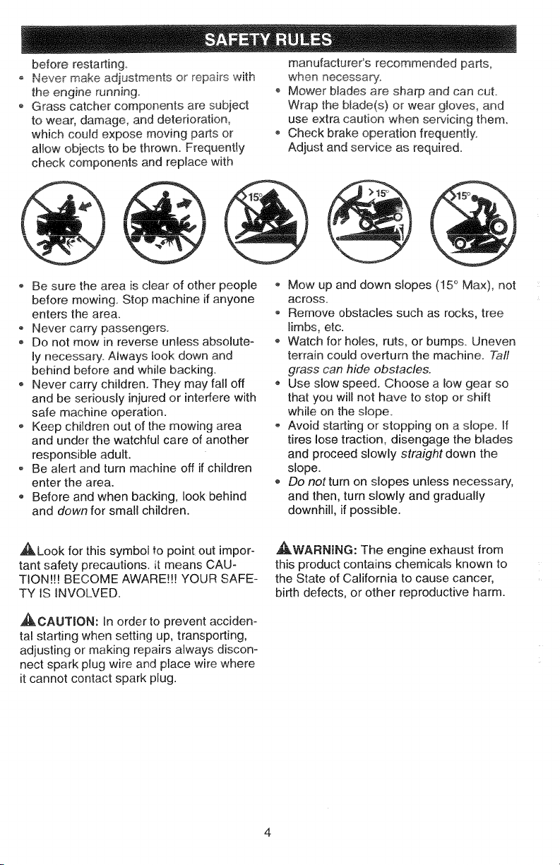
Mow up and down slopes (15° Max), not
across.
Remove ,obstacles such as rocks, tree
limbs, etc.
® Watch for holes, ruts, or bumps Uneven
terrain could overturn the machine. Taft
grass can hide obstacles.
• Use slow speed. Choose a low gear so
that you will not have to stop or shift
while on the slope.
Avoid starting or stopping on a slope. If
tires lose traction, disengage the blades
and proceed slowly straight down the
slope.
Do not turn on slopes unless necessary,
and then, turn slowly and gradually
downhill, if possible.
_WARNJNG: The engine exhaust from
this product contains chemicals known to
the State of California to cause cancer,
birth defects, or other reproductive harm.
Page 5
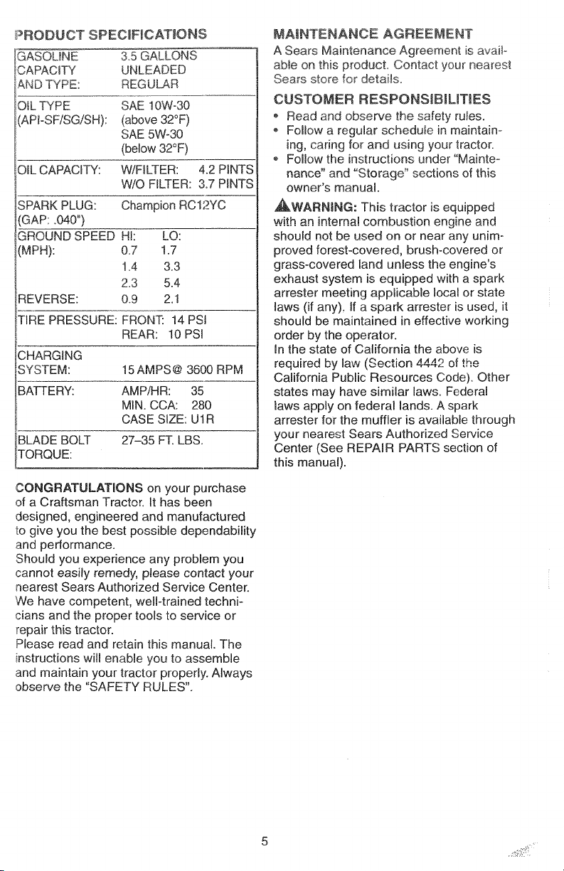
I_RODUCTSPECmFJCATJONS
GAS©UNE 35GALLONS
CAPACITY UNLEADED
ANDTYPE: REGULAR
OiLTYPE SAE10W-30
(API°SFiSG/SH):(above32°F)
SAE5W-30
_ (below32°F)
OILCAPACITY:W/FILTER:4.2PINTS
W!OFILTER:3.7PINTS
._PARKPLUG: Champion RC12YC
GAP: _040")
GROUND SPEED H!: LO:
(MPH): 0.7 1.7
1.4 3.3
2.3 5.4
REVERSE: 0.9 2.1
TIRE PRESSURE: FRONT: 14 PSI
REAR: 10 PSI
CHARGING
SYSTEM: 15 AMPS@ 3600 RPM
BATTERY: AMP/HR: 35
MIN. CCA: 280
CASE SIZE: U1R
BLADE BOLT 27-35 FT. LBS.
TORQUE:
MAINTENANCE AGREEMENT
A Sears Maintenance Agreement is avaiF
able on this product Contact your nearest
Sears store for details.
CUSTOMER RESPONSIBILmES
Read and observe the safety ruJes.
Follow a regular schedule in maintain-
ing, caring for and using your tractor.
* Follow the instructions under"Mainte-
nance" and "Storage" sections of this
owner's manual
_WARNJNG: This tractor is equipped
with an interna! comb_st.on engine and
shouid not be used on or near any unim-
proved forest-covered, brush-covered or
grass-covered land unless the engine's
exhaust system is equipped with a spark
arrester meeting appJicaMe local or state
laws (if any), If a spark attester is used, it
should be maintained in effective working
order by the operator.
In the state of California the above is
required by law (Section 4442 of the
California Public Resources Code). Other
states may have similar laws. Federal
laws apply on federal lands. A spark
arrester for the muffler is available through
your nearest Sears Authorized Service
Center (See REPAIR PARTS section of
this manual).
CONGRATULATIONS on your purchase
of a Craftsman Tractor. It has been
designed, engineered and manufactured
to give you the best possible dependability
and performance.
Should you experience any problem you
cannot easily remedy, please contact your
nearest Sears Authorized Service Center.
We have competent, weIFtrained techni-
cians and the proper tools to service or
repair this tractor.
Please read and retain this manual. The
instructions will enable you to assemble
and maintain your tractor properly. Always
observe the "SAFETY RULES".
5
Page 6
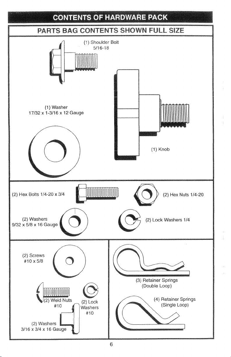
PARTS BAG CONTENTS SHOWN FULL SIZE
(1) ShouJder Bolt
5/16-18
(1) Washer
17/32 x 1-3/16 x 12 Gauge
(!) Knob
(2) Hex Bolts 1/4-20 x 3/4
9/32 x B/8 x 16 Gauge
(2) Washers
(2) Screws
#10 x 5/8
_s (2) Locq
#1_ Washers#10
(2) Washers _ I
3/16 x 3/4 x16 Gauge _ j
(2) Hex Nuts 1/4-20
(2) Lock Washers 1/4
(3) Retainer Springs
(Double Loop)
Page 7
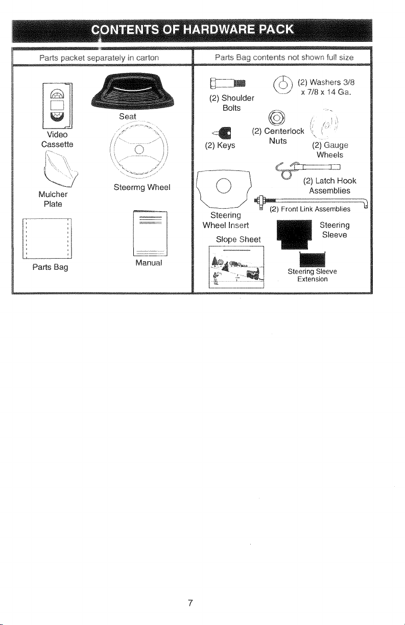
PartspacketseparateIyncarton
Seat
Video
Cassette
i
Parts Bag contents not shown fut! size
(2} Washers 3/8
(2) Shoulder
Bolts
x 7/8 x 14 Ga.
/21coo,er,ock
(2) Keys (2) Gauge
Nuts
Wheels
Mulcher
Plate
PartsBag
SteermgWheel
Manual
L? /(_ _ (2) Latch Hook
_,_nt LinkAssemblies
Steering
Wheel Insert
Slope Sheet
Assemblies
Steering
Sleeve
m
Steering Sleeve
Extension
7
Page 8
Yournewtractorhasbeenassembledatthefactorywithexception of those parts left
unassembled for shipping purposes. To ensure safe and proper operation of your tractor
all parts and hardware you assemMe must be tightened securely. Use the correct tools
as necessary to insure proper tightness Review the video cassette before you begin.
TOOLS REQUIRED FOR
ASSEMBLY
A socketwrench set will make assembly
easier, Standardwrench sizes you need
are listed below.
(1) 9/16" wrench (1) 3/4" Socket wi
(2) 7/16" wrenches drive rachet
(!) !/2" wrench (!) Phillips Screw °
(1) Utility knife driver
(t)Pliers (1) Tire pressure
gauge
When right or left hand is mentioned in
this manual, it means, from your point of
view, when you are in the operating posi-
tion (seated behind the steering wheel).
TO REMOVE TRACTOR FROM
CARTON
UNPACK CARTON
Remove all accessible loose parts and
parts boxes from shipping carton (See
page 6).
Cut, from top to bottom, along lines on
all four corners of shipping carton, and
lay panels flat.
Remove mower and package materials.
Check for any additiona! loose parts or
boxes and remove.
BEFORE ROLLING TRACTOR OFF
SKiD
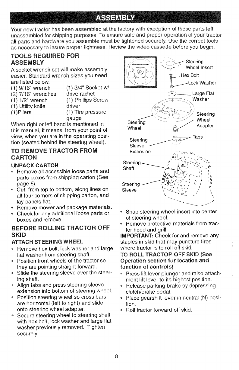
ATTACH STEERING WHEEL
® Remove hex bolt, lock washer and large
flat washer from steering shaft.
o Position front wheels of the tractor so
they are pointing straight forward.
o Slide the steering sleeve over the steer-
ing shaft.
- Align tabs and press steering sleeve
extension into bottom of steering wheel.
Position steering wheel so cross bars
are horizontal (left to right) and slide
onto steering wheel adapter.
o Secure steering wheel to steering shaft
with hex bolt, lock washer and large fiat
washer previously removed. Tighten
securely.
Steerinc
Sleeve
• Snap steering wheel insert into center
of steering wheel.
Remove protective materials from trac-
tor hood and grill.
iMPORTANT: Check for and remove any
staples in skid that may puncture tires
where tractor is to roll off skid.
TO ROLL TRACTOP OFF SKID (See
Operation section for _ocation and
function of controls)
® Press lift lever plunger and raise attach°
ment lift lever to its highest position.
Release parking brake by depressing
clutch/brake pedal.
o Place gearshift lever in neutral (N) posi-
tion.
o Roll tractor forward off skid.
Page 9

HOWTOSETUPYOURTRACTOR
CONNECTBAKERY
,_CAUTION: Do not short battery termi-
nais by aliowing a wrench or any other
object to contact both terminals at the
same time. Before connecting battery,
remove metal bracelets, wristwatch bands,
rings_ etc. Positive terminal must be con-
nected first to prevent sparking from accio
dental grounding.
,, Lift hood to raised position.
o Open terminal access doors, remove
terminal protective caps and discard.
ti¢ _, ,
,, ,h_s battery' is put into service after
month _,,_'4,uyear _<,4_ _ .4 _h_/_,_
located between terminals) charge _'-'
tery for minimum of one hour at 6-10
amps.
o First connect RED battery cabte to posi-
tive (+) battery terminal with hex bolt, flat
washer, lock washer and hex nut as
shown. Tighten securely.
,, Connect BLACK grounding cable to
negative (-) battery termina! with remain-
ing hex bolt, flat washer, lock washer
and hex nut. Tighten securely.
,, Close terminal access doors.Use termi-
nal access doors for:
, Inspection for secure connections (to
tighten hardware).
® Inspection for corrosion.
,, Testing battery.
o Jumping (if required).
Periodic charging.
DiscardTerminal
ProtectiveCaps
Lock
Washer / Hex
x Nut
,i' I i,
-- (Red)
Terminal _tive
Access Door / ...... (Black)
Cable
INSTALL SEAT
Adjust seat before tightening adjustment
knob.
Remove cardboard packing on seat pan.
LJ*:_L"
Flat
Washer
Bolt
Positive
Cable
• Place seat on seat pan and assemb!e
shoutder bolt. Tighten shoutder bolt
securely.
o Assemble adiustment knob and f!at
washer loosely. Do not tighten.
o Lower seat into operating position and
sit on seat.
o Slide seat until a comfortable position is
reached which allows you to press
clutch/brake pedal all the way down.
o Get off seat without moving its adjusted
position.
o Raise seat and tighten adjustment knob
securely.
Seat
Shoulder \
FlatWasher
Adjustment Knob
CHECK TIRE PRESSURE
The tires on your tractor were overinflated
at the factory for shipping purposes.
Correct tire pressure is important for best
cutting performance.
® Reduce tire pressure to PSI shown in
"PRODUCT SPECIFICATIONS" on page
5 of this manual.
CHECK BRAKE SYSTEM
After you team how to operate your tractor,
check to see that the brake is properly
adjusted. See "TO ADJUST BRAKE" in the
Service and Adjustments section of this
manual.
mNSTALL MOWER AND DRIVE BELT
Be sure tractor is on level surface and
mower suspension arms are raised with
attachment lift control. Engage parking
brake.
o Cut and remove ties securing anti-sway
bar and belts. Swing anti-sway bar to
left side of mower deck.
, Slide mower under tractor with dis-
charge guard to right side of tractor.
Page 10
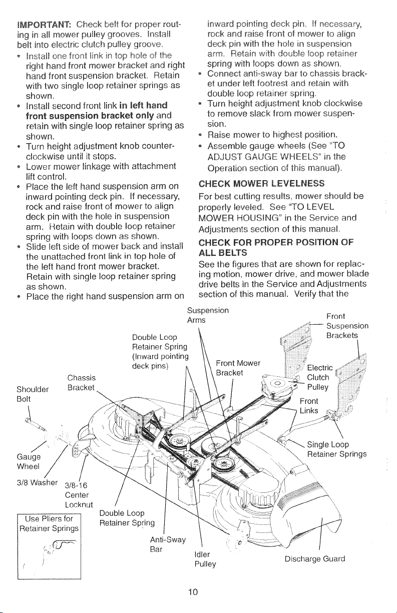
iMPORTANT:Checkbeltforproperrout°
inginallmowerpulleygrooves.Install
beltintoelectricclutchpuileygroove.
oinstallonefrontlinkintopholeofthe
righthandfrontmowerbracketandright
handfrontsuspensionbracketRetain
withtwosingleloopretainerspringsas
shown.
installsecondfrontlinkin left hand
front suspension bracket only and
retain with single loop retainer spring as
shown.
o Turn height adjustment knob counter-
t,_,Jcr_vwo_ it
o _.......... we, linkage with attachment
lift control.
o Place the left hand suspension arm on
inward pointing deck pin. if necessary,
rock and raise front of mower to align
deck pin with the hole in suspension
arm. Retain with double loop retainer
spring with loops down as shown.
o Slide left side of mower back and install
the unattached front link in top hole of
the left hand front mower bracket.
Retain with single loop retainer spring
as shown.
,, Place the right hand suspension arm on
Shoulder
Bolt
ul iLii .:__v[M o.
Double Loop
Retainer Spring
(Inward pointing
deck pins)
Chassis
Bracket
inward pointing deck pin. If necessary,
rock and raise front of mower to atign
deck pin with the hole in suspension
arm. Retain with double Ioop retainer
spring with toops down as shown.
Connect anti-sway bar to chassis brack-
et under left footrest and retain with
double loop retainer spring.
Turn height adjustment knob clockwise
to remove slack from mower suspen-
sion.
Raise mower to highest position.
Assemble gauge wheels (See "TO
ADJUST GAUGE WHEELS" in the
Operation section of this manual).
CHECK MOWER LEVELNESS
For best cutting results, mower should be
properly leveled. See "TO LEVEL
MOWER HOUSING" in the Sen,ice and
Adjustments section of this manual
CHECK FOR PROPER POSITnON OF
ALL BELTS
See the figures that are shown for replac-
ing motion, mower drive, and mower blade
drive belts in the Service and Adjustments
section of this manual. Verify that the
Suspension
Arms Front
Brackets
Front Mower
Bracket
/
Clutch_'_
_
Gauge
Wheel
3/8 Washer 3/8-16
Center
Locknut
Use Pliers for
Retainer Springs
/ /
Double Loop
Retainer Spring
Anti-Sway
Bar
10
Idler
Pulley
\
igle Loop
_\ Retainer Springs
\\
\\
,i_ _,1 I
Discharge Guard
Page 11
beltsareroutedcorrectly.
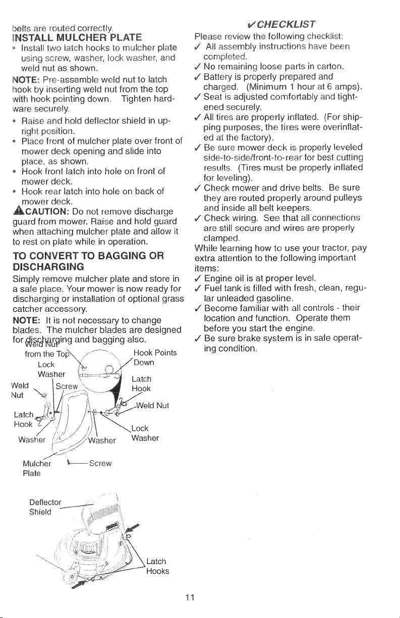
_NSTALLMULCHERPLATE
_,installtwolatchhookstomulcherplate
usingscrew,washer,_ockwasher,and
weldnutasshown.
NOTE:Pre-assembleweldnuttolatch
hookbyinsertingweldnutfromthetop
withhookpointingdown Tightenhard-
waresecurely.
oRaiseandholddeflectorshieldinup-
rightposition.
• Placefrontofmulcherplateoverfrontof
mowerdeckopeningandslideinto
place,asshown.
Hookfrontiatchintoholeonfrontof
mowerdeck.
Hookrearlatchintoholeonbackof
mowerdeck.
,_CAUTRON: Do not remove discharge
guard from mower. Raise and hold guard
when attaching mulcher plate and allow it
to rest on plate while in operation.
TO CONVERT TO BAGGING OR
DiSCHARGiNG
Simply remove mulcher plate and store in
a safe place. Your mower is now ready for
discharging or installation of optional grass
catcher accessory.
NOTE: It is not necessary to change
blades. The mulcher blades are designed
for_r_ing and bagging also.
from the Topx.. _--" \ Hook Points
Lock "_ _'. JDown
Washer ;........ _ Latch
Weld -.. ! Hook
Nut _ / _"
Latchji :)
IScrew\
" _..jWeld Nut
_CHECKMST
Please review the following checklist:
,/ All assembly instructions have been
completed.
7" No remaining loose parts in carton.
¢" Battery is properly prepared and
charged. (Minimum 1 hour at 6 amps).
,/Seat is adjusted comfortably and tight-
ened securely.
,/All tires are properly inflated. (For ship-
ping purposes, the tires were overinflat-
ed at the factory,).
,/Be sure mower deck is property leveled
side4o-side!front4o-rear for best cutting
results (Tires must be properly inflated
for leveling).
V Check mower and drive belts. Be sure
they are routed properly around pulleys
and inside all belt keepers.
,/Check wiring. See that all connections
are still secure and wires are properly
clamped.
While learning how to use your tractor, pay
extra attention to the following important
items:
,/Engine oil is at proper level.
,/Fuel tank is filled with fresh, clean, regu-
lar unleaded gasoline
,/Become familiar with all controls - their
location and function. Operate them
before you start the engine.
¢ Be sure brake system is in safe operat-
ing condition.
Hook_:/// /!Jt_/_asher_LOck
Washer i(':t; Washer
.....¢S
Mulcher _---Screw
Plate
Latch
Hooks
11
Page 12
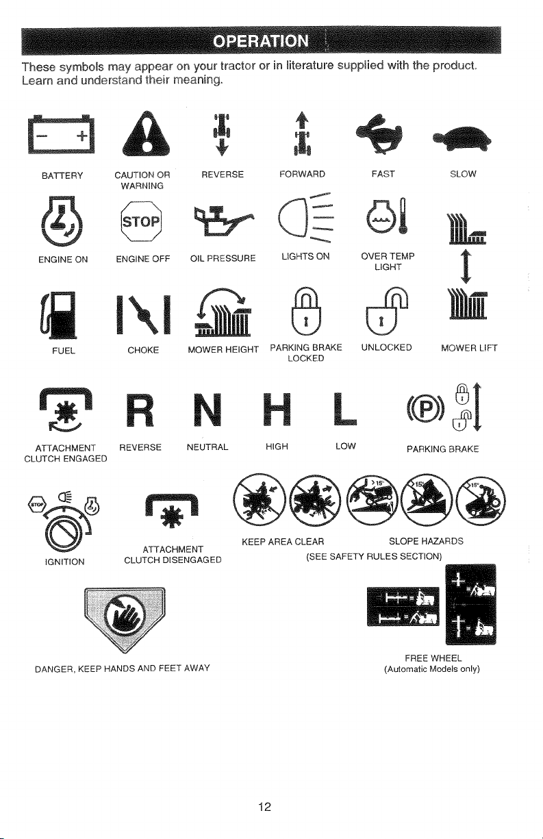
Thesesymbolsmayappearonyourtractororinliteraturesuppliedwiththeproduct
Learnandunderstandtheirmeaning.
BATTERY
ENGINE ON
FUEL
ATTACHMENT
CLUTCH ENGAGED
IGNITION
CAUTION OR REVERSE FORWARD
WARNING
ENGINE OFF OIL PRESSURE LIGHTS ON
l\l 0
CHOKE MOWER HEIGHT PARKING BRAKE
REVERSE NEUTRAL HIGH
ATTACHMENT
CLUTCH DISENGAGED
KEEP AREA CLEAR SLOPE HAZARDS
LOCKED
(SEE SAFETY RULES SECTION)
FAST
SLOW
&a
OVER TEMP
LIGHT
UNLOCKED
MOWER LIFT
L (®)_i
LOW PARKING BRAKE
DANGER, KEEP HANDS AND FEET AWAY
FREE WHEEL
(Automatic Models only)
12
Page 13

KNOWYOUR TRACTOR
READ THIS OWNER'S MANUAL AND SAFETY RULES BEFORE OPERATING YOUR
TRACTOR
Compare the iHustratior_s with your tractor to familiarize yourself with the locations of
various controls and adjustments. Save this manual for future reference.
Light Switch
Ignition
Switch
Ammeter
Throttle Control
J i_"_Lift Lever
Position
Attachment
CRutch Switch
Clutch/Brake
Pedal
Choke
Height
Adjustment
Knob
Our tractors co:qform to the safety standards of the American
National Standards Institute,
ATTACHMENT CLUTCH SWITCH: Used
to engage the mower blades, or other at-
tachments mounted to your tractor.
LIGHT SWITCH: Turns the headlights on
and off,
THROTTLE CONTROL: Used to control
engine speed.
CLUTCH/BRAKE PEDAL: Used for
declutching and braking the tractor and
starting the engine.
CHOKE CONTROL: Used when starting a
cold engine,
HEIGHT ADJUSTMENT KNOB: Used to
adjust the mower cutting height.
_ Ptunger
/ / Attachment
_/ Lift Lever
Parking Brake
GEARSHIFT LEVER: Selects the speed
and direction of the tractor.
RANGESHIFT LEVER: Allows high (H)
and low (L) speed for all forward and
reverse gears.
ATTACHMENT LIFT LEVER: Used to
raise and lower the mower deck or other
attachments mounted to your tractor.
LIFT LEVER PLUNGER: Used to release
attachment lift lever when changing its
position.
IGNITION SWITCH: Used for starting and
stopping the engine.
AMMETER: Indicates battery charging (+)
or discharging (-).
PARKING BRAKE: Locks clutch/brake
13
Page 14
HOWTOUSEYOURTRACTOR
Yourtractorisequippedwithanoperator
presencesensingswitch_Whenengineis
running,anyattemptbytheoperatorto
_eavetheseatwithoutfirstsettingthe
parkingbrakewinshutofftheengine°
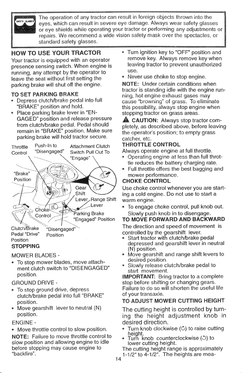
TOSETPARKINGBRAKE
,,Depressdutch!brakepeda!intofun
"BRAKE"positionandhold.
o Placeparkingbrakeleverin"EN-
GAGED"positionandreleasepressure
fromclutch/brakepedal.Pedalshould
remainin"BRAKE"position.Makesure
parkingbrakewil!holdtractorsecure.
Throttle Push-in to Attachment Clutch
Control "Disengaged" Switch Pull Out To
"Engage"
"Brake"
Position
.Lever
_gBrake
"Engaged"Position
C
Pedal "Drive"
Position
STOPPING
MOWER BLADES -
To stop mower blades, move attach-
ment clutch switch to "DISENGAGED"
position.
GROUND DRIVE -
To stop ground drive, depress
clutch/brake pedal into full "BRAKE"
position.
Move gearshift lever to neutral (N)
position.
ENGINE -
® Move throttle control to slow position.
NOTE: Failure to move throttle control to
slow position and allowing engine to idle
before stopping may cause engine to
"backfire".
"Disengaged'""
Position
Turn ignition key to "OFF" position and
remove key. Always remove key when
leaving tractor to prevent unauthorized
use.
Never use choke to stop engineo
NOTE: Under certain conditions when
tractor is standing idle with the engine run-
ning, hot engine exhaust gases may
cause "browning" of grass. "Toeliminate
this possibility, always stop engine when
stopping tractor on grass areas.
CAUTION: Always stop tractor com-
pletely, as described above, before leaving
the operator's position; to empty grass
catcher, etc.
THROTTLE CONTROL
Always operate engine at full throttle.
- Operating engine at !ess than full throt-
tle reduces the battery charging rate.
Full throttle offers the best bagging and
mower performance.
CHOKE CONTROL
Use choke control whenever you are start-
ing a cold engine. Do not use to start a
warm engine.
,, To engage choke control, pull knob out.
Slowly push knob in to disengage.
TO MOVE FORWARD AND BACKWARD
The direction and speed of movement is
controlled by the gearshift lever.
® Start tractor with clutch/brake pedal
depressed and gearshift lever in neutral
(N) position.
o Move gearshift and range shift levers to
desired position.
Slowly re_ease clutch/brake pedal to
start movement.
mMPORTANT: Bring tractor to a complete
stop before shifting or changing gears.
Failure to do so will shorten the useful life
of your transaxle.
TO ADJUST MOWER CUTTING HEIGHT
The cutting height is controlled by turn-
ing the height adjustment knob in
desired direction.
Turn knob clockwise (©) to raise cutting
height.
® Turn knob counterclockwise (O) to
lower cutting height.
The cutting height range is approximately
1-1/2" to 4ol/2 ". The heights are mea-
l4
Page 15
suredfromthegroundtothebtadetipwith
theenginenotrunning.Theseheightsare
approximateandmavarydepending
uponsoitconditions,_eightofgrassand
typesofgrassbeingmowed.
Theaveragelawnshouldbecutto
approxmate_y2-1/2inchesduringthe
coolseasonandtoover3inchesduring
hotmonths.Forhealthierandbetter
lookinglawns,mowoftenandafter
moderategrowth.
Forbestcuttingperformance,grass
over6inchesinheightshouldbe
mowedtwice°Makethefirstcutrela-
tive!yhigh;thesecondtodeskedheighL
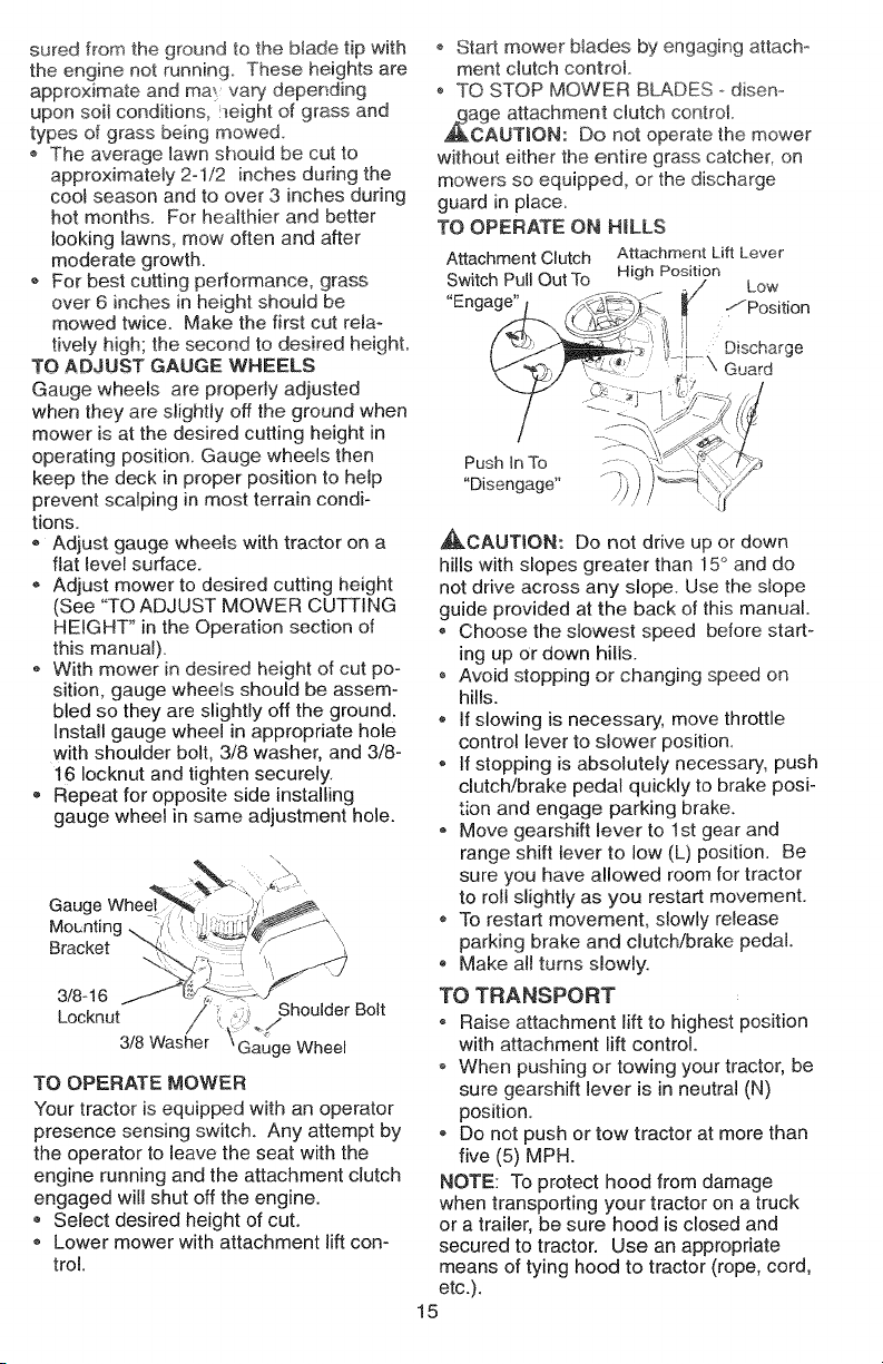
TO ADJUST GAUGE WHEELS
Gauge wheels are properly adjusted
when they are slightly off the ground when
mower is at the desired cutting height in
operating position. Gauge wheels then
keep the deck in proper position to help
prevent scalping in most terrain condi-
tions.
Adjust gauge wheels with tractor on a
ftat tevel surface.
Adjust mower to desired cutting height
(See "TO ADJUST MOWER CUTTING
HEIGHT" in the Operation section of
this manual).
• With mower in desired height of cut poo
sition, gauge wheels should be assem-
bled so they are slightly off the ground.
Install gauge wheel in appropriate hole
with shoulder bolt, 3/8 washer, and 3/8-
16 Iocknut and tighten securely.
® Repeat for opposite side installing
gauge wheel in same adjustment hole.
Gauge
Mounting
Bracket \
3/8- 16
Locknut ,,, ,_j
3/8 Washer \Gauge Wheel
TO OPERATE MOWER
Your tractor is equipped with an operator
presence sensing switch. Any attempt by
the operator to leave the seat with the
engine running and the attachment clutch
engaged will shut off the engine.
• Select desired height of cut.
o Lower mower with attachment lift con-
trol.
Shou der Bolt
Start mower blades by engaging attach°
ment clutch control.
o TO STOP MOWER BLADES disen.-
ge attachment ctutch contro_
AUTmON: Do not operate the mower
without either the entire grass catcher, on
mowers so equipped, or the discharge
guard in place.
TO OPERATE ON H_LLS
Attachment Clutch Attachment Lift Lever
Switch Pull Out To High Position
"Engage" -/Position
Push InTo _/:
"Disengage" _)'))
,_CAUTION: Do not drive up or down
hills with slopes greater than 15° and do
not drive across any slope. Use the slope
guide provided at the back of this manual.
Choose the slowest speed before start-
ing up Ordown hills.
o Avoid stopping or changing speed on
hills.
If slowing is necessary, move throttle
control lever to slower position.
If stopping is absolutely necessary, push
clutch!brake pedal quickly to brake posi-
tion and engage parking brake.
* Move gearshift lever to 1st gear and
range shift lever to low (L) position. Be
sure you have allowed room for tractor
to roll slightly as you restart movement.
To restart movement, slowly release
parking brake and clutch/brake pedal.
* Make al! turns slowly.
TO TRANSPORT
- Raise attachment lift to highest position
with attachment lift control.
o When pushing or towing your tractor, be
sure gearshift lever is in neutral (N)
position.
° Do not push or tow tractor at more than
five (5) MPH.
NOTE: To protect hood from damage
when transporting your tractor on a truck
or a trailer, be sure hood is closed and
secured to tractor. Use an appropriate
means of tying hood to tractor (rope, cord,
etc.).
15
Low
Discharge
Guard
Page 16
TOWINGCARTSANDOTHER
A_ACHMENTS
Towonlytheattachmentsthatarerecom-
mendedbyandcomplywithspecifications
ofthemanufacturerofyourtractor.Use
commonsensewhentowingTooheavyof
aload,whileonastope,isdangerous
Tirescanlosetractionwiththegroundand
causeyoutolosecontrolofyourtractor
BEFORESTARTINGTHEENGINE
CHECKENGINEOILLEVEL
Theengineinyourtractorhasbeen
shipped,fromthefactory,alreadyfilled
withsummerweightoil.
Checkengineoilwithtractoronlevel
ground.
Unthreadandremoveoilfillcap/dip-
stick;wipeoiloff.Reinsertthedipstick
intothetubeandrestoilfillcaponthe
tube.Donotthreadthecapontothe
tube.Removeandreadoillevel.Ifnec-
essary,addoiluntil'FULL"markon
dipstickisreached.Donotovedi!l
Forcoldweatheroperationyoushould
changeoilforeasierstarting(See"OIL
VISCOSITYCHART"intheCustomer
Responsibilitiessectionofthismanua!).
oTochangeengineoil,seetheCustomer
Responsibilitiessectioninthismanual.
ADDGASOLINE
, Fillfueltank.Usefresh,clean,regular
unleadedgasolinewithaminimumof87
octane.(Useofleadedgasolinewill
increasecarbonandleadoxide
depositsandreducevalvelife).Donot
mixoilwithgasolinePurchasefue!in
quantitiesthatcanbeusedwithin30
daystoassurefuelfreshness.
IMPORTANT:Whenoperatingintempera-
turesbelow32'_F(0°C),usefresh,dean
wintergradegaso!inetohelpinsuregood
,_d weather starting.
WARNING: Experience indicates that
alcohol blended fuels (called gasohol or
using ethanol or methanol) can attract
moisture which leads to separation and
formation of acids during storage. Acidic
gas can damage the fuel system of an
engine while in storage. To avoid engine
problems, the fuel system should be emp-
tied before storage of 30 days or longer.
Drain the gas tank, start the engine and let
it run until the fuel lines and carburetor are
empty. Use fresh fuel next season. See
Storage Instructions for additional
16
information Never use engine or
carburetor cleaner products in the fuel
tank or permanent damage may occur.
,_CAUTRON: Fill to bottom of gas tank
filler neck. Do not overfill. Wipe off any
spilled oil or fuel. Do not store, spitl or use
gasoline near an open flame
TO START ENGINE
When start ng the engine for the first time
or if the engine has run out of fuel, it wil!
take extra cranking time to move fuel from
the tank to the engine.
o Sit on seat in operating position,
depress clutch/brake pedal and set
parking brake.
,, Place gear shift lever in neutral (N)
position.
o Move attachment clutch to "DISEN-
GAGED" position.
Move throttle control to fast position
,, Pull choke control out for a cold engine
start attempt. For a warm engine start
attempt the choke control may not be
needed.
Note: Before starting, read the warm and
cold starting procedures below.
Insert key into ignition and turn key
clockwise to "START" position and
release key as soon as engine starts.
Do not run starter continuously for more
than fifteen seconds per minute. If the
engine does not start after several
attempts, push choke control in, wait a
few minutes and try again. If engine still
does not start, pull the choke control out
and retry.
WARM WEATHER STARTING (500 F
AND ABOVE)
When engine starts, slowly push choke
control in until the engine begins to run
smoothly. If the enyine starts to run
roughly pull the choke control out slight-
ly for a few seconds and then continue
to push the control in slowly.
o The attachments and ground drive can
now be used. If the engine does not
accept the load, restart the engine and
allow it to warm up _orone minute using
the choke as described above.
COLD WEATHER STARTING (50° F AND
BELOW)
When engine starts, slowly push choke
control in until the engine begins to run
smoothly. Continue to push the choke
control in small steps allowing the
Page 17
enginetoacceptsmallchangesin
speedandload,unt_thechokecontrol
isfullyin.tftheengi_estartstorun
rougHy_pullthechokecontro!outslighto
lyforafewsecondsandthencontinue
topushthecontrolinslowly.Thismay
requireanenginewarmoupperiodfrom
severalsecondstoseveralminutes,
dependingonthetemperature.
Theattachmentscanbeuseddudng
theenginewarm-upperiodandmay
requirethechokecontrolbeputtedout
slightly.
NOTE:Ahighaltitude(above3000feet)
orincoldtemperatures(below32F)the
carburetorfuelmixturemayneedtobe
adjustedforbestengineperformance.
See"TO ADJUST CARBURETOR _ in the
Service and Adjustments section of this
manual
MOWING TiPS
o Tire chains cannot be used when the
mower housing is attached to tractor.
® Mower should be properly leveled for
best mowing performance. See "TO
LEVEL MOWER HOUSING" in the
Service and Adjustments section of this
manual.
The left hand side of mower should be
used for trimming.
- Drive so that clippings are discharged
onto the area that has been cut. Have
the cut area to the right of the tractor.
This will result in a more even distribu-
tion of clippings and more uniform cut-
ting.
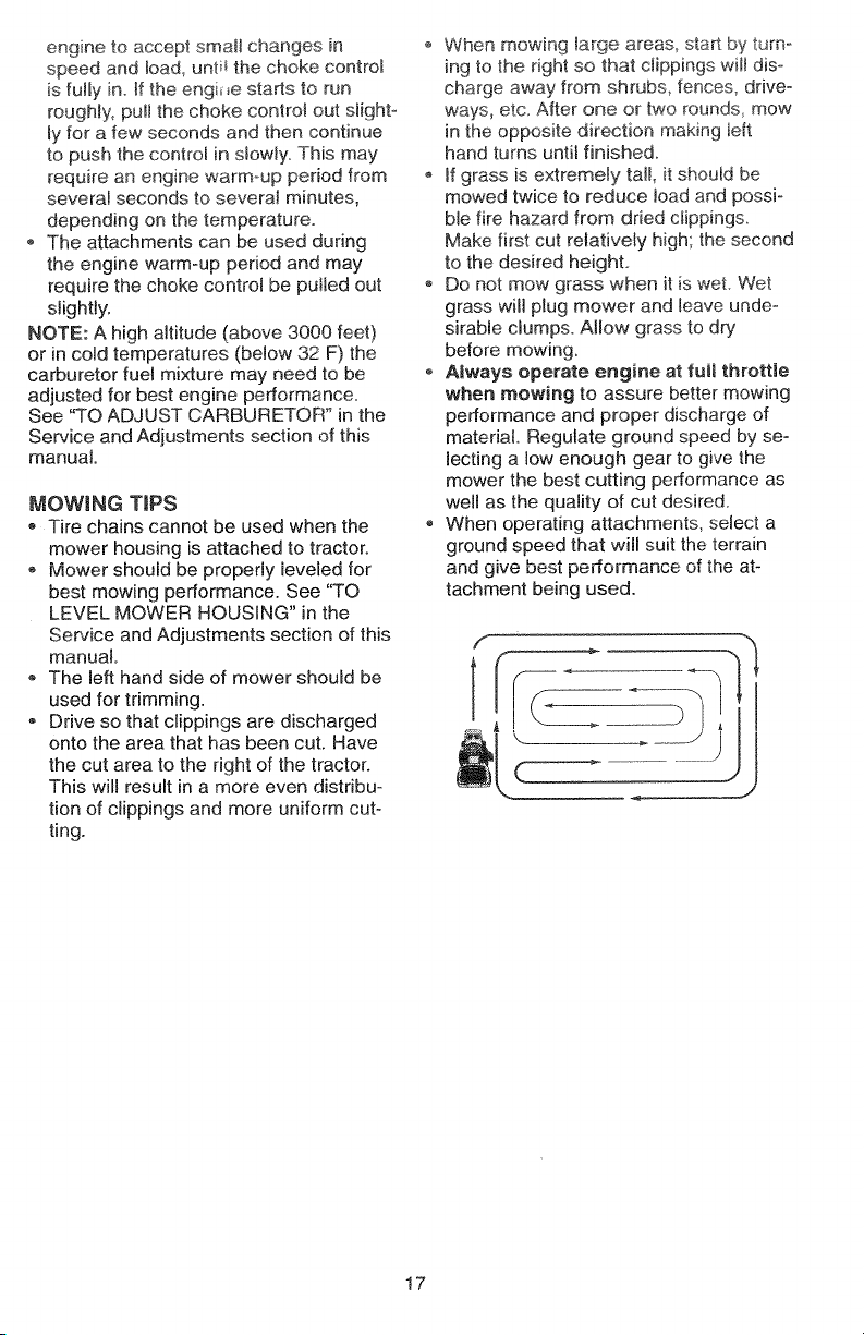
o When mowing large areas_ sta_ by turn°
ing to the right so that clippings wilt dis-
charge away from shrubs, fences, drive-
ways, etc. After one or two rounds, mow
in the opposite direction making left
hand turns until finished.
o If grass is extremely tall, it should be
mowed twice to reduce load and possi-
ble fire hazard from dried clippings.
Make first cut relatively high; the second
to the desired height.
Do not mow grass when it is wet. Wet
grass will plug mower and leave unde-
sirable clumps. Allow grass to dry
before mowing.
® Always operate engine at _uii throttie
when mowing to assure better mowing
performance and proper discharge of
material. Regulate ground speed by se-
lecting a low enough gear to give the
mower the best cutting performance as
well as the quality of cut desired.
, When operating attachments, select a
ground speed that will suit the terrain
and give best performance of the at-
tachment being used.
f
7
lj
17
Page 18
MULCHINGMOWINGT_PS
8MPORTANT_Forbestperformance,keep
mowerhousingfreeofbuilt-upgrassand
trashC!eanaftereachuse_
Thespecialmulchingbladewil!recut
thegrassclippingsmanytimesand
reducetheminsizesothatastheyfall
ontothelawntheywilldisperseintothe
grassandnotbenoticed°Also,the
mulchedgrasswillbiodegradequickly
toprovidenutrientsforthelawn.Always
mulchwithyourhighestengine(blade)
speedasthiswillprovidethebestrecut-
tingactionoftheblades.
oAvoidcuttingyourlawnwhenitiswet.
Wetgrasstendstoformc_umpsand
interfereswiththemulchingaction.The
besttimetomowyourlawnistheearly
afternoon.Atthistimethegrasshas
driedandthenewlycutareawillnotbe
exposedtothedirectsun.
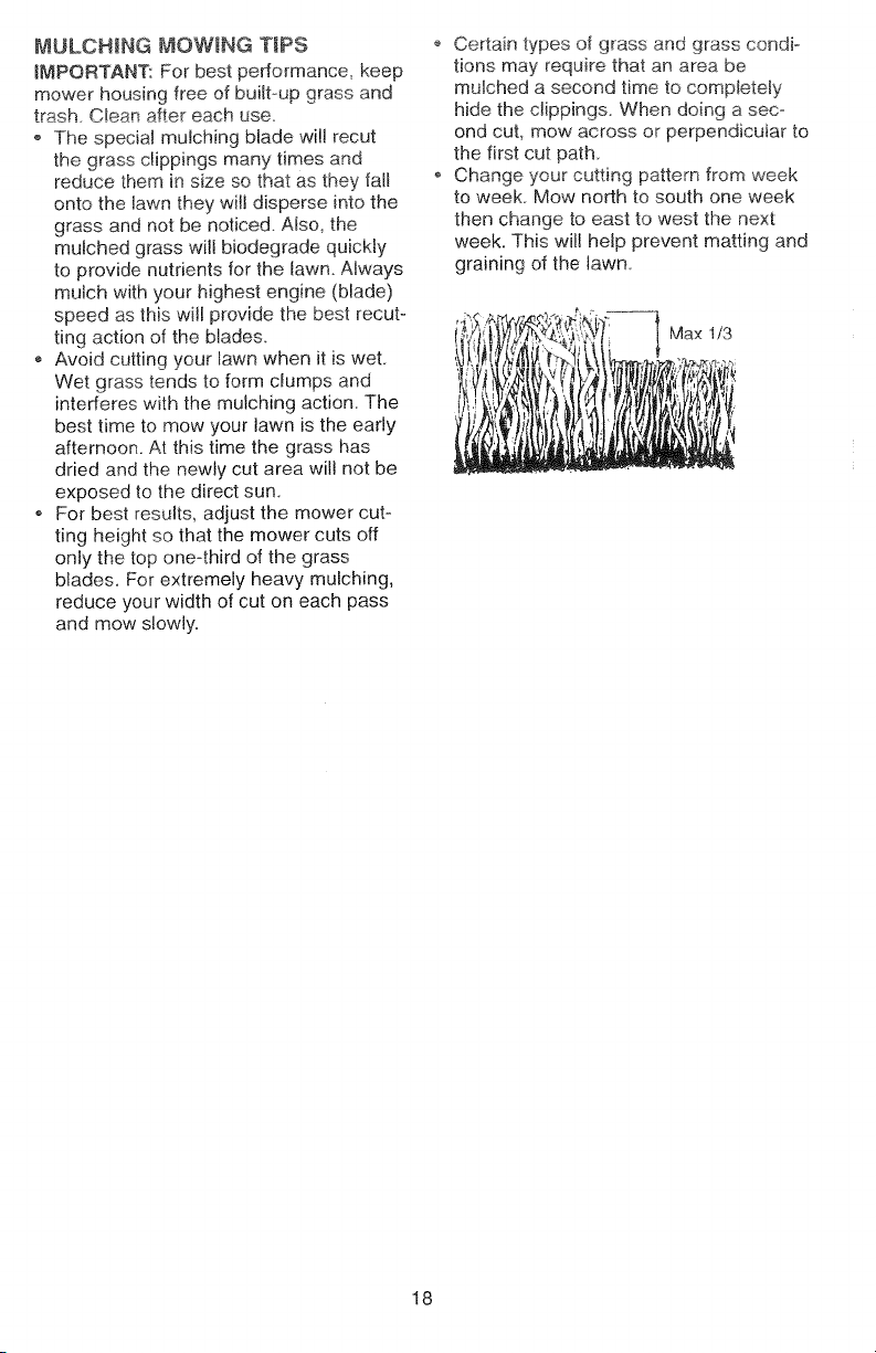
oForbestresults,adjustthemowercut-
tingheightsothatthemowercutsoff
onlythetoponeothirdofthegrass
blades.Forextremelyheavymulching,
reduceyourwidthofcutoneachpass
andmowslowly.
oCertaintypesofgrassandgrasscondi_
tionsmayrequirethatanareabe
mulchedasecondtimetocompletely
hidetheclippings.Whendoingaseco
ondcut,mowacrossorperpendicularto
thefirstcutpath.
oChangeyourcuttingpatternfromweek
toweek.Mownorthtosouthoneweek
thenchangetoeasttowestthenext
week.Thiswillhelppreventmattingand
grainingofthelawn.
" 1 Max 1/3
18
Page 19
CUSTOMERRESPONSiBiLITiES
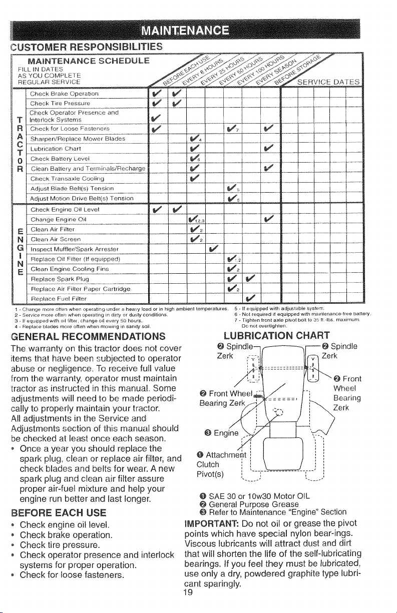
MAINTENANCE SCHEDULE
F_LL IN DATES
AS YOU COMPLETE
REGULARSERV/C__ E ....
Check Brake Operation
CheekOper,to+P_e............d ..,, , , ,,o., I I I ! I
Sh+pe , R+t°ceM.....Bides l
Check Battery Levei
M Ciean Ba_.ery and Te_ rdnals/Recharge
Check Trarlsax_2 Co?tin2 ...........
Adjust Blade Belt(s) Tension
Adjust Motion Drive Belt(s) Tension
Check Engine Oil Level
Change Engine Oil
NE Clean Air Filter
Clean Air Screen
G Enspect Muffler/Spark Arrester
Reptace Oi! Fitter (If equipped)
N
E Clean Engine Cooling Fins
R.eplace spar _ Plug ............................
.......F-- ++ __ __
-2-7
_,,/a
______v_!
+q+--i--P.........!........
..... e
Replace Fuel Filter
+Change t'r_o+eotlen when _%_erat nO under a heavy load or in high ambient temperatures 5 - If equipped with adjustable system
+ Service mo+e often when operat ng in drty or dusty conditions.
+ if eq_+_pped with e_l filter, change o_1 every 50 hours.
+ Repl_*ce blades mo_e often when rrvow ng in sandy soil
GENERAL RECOMMENDATIONS
The warranty on this tractor does not cover
items that have been subjected to operator
6 + Not required if equipped with maintenance ftee battery
7 - Tighten front axle pivot bolt to 35 II +lbs maximum
Do not overtighten.
LUBRICATION CHART
@ S Spindle
Zerk r-:__ Zerk
abuse or negligence. To receive full value
from the warranty, operator must maintain
tractor as instructed in this manual. Some
adjustments will need to be made periodi-
cally to properly maintain your tractor.
@ Front Wheel
Bearing Zerk
All adjustments in the Service and
Adjustments section of this manual should
be checked at least once each season.
+ Once a year you should replace the
spark plug, clean or replace air filter, and
check blades and belts for wear. A new
spark plug and clean air filter assure
proper air-fuel mixture and help your
engine run better and last longer.
BEFORE EACH USE
, Check engine oil level.
, Check brake operation.
Check tire pressure.
, Check operator presence and interlock
systems for proper operation.
, Check for loose fasteners.
O Engine
@Attachment
Clutch
Pivot(s) ',
@SAE 30 or 10w30 Motor OIL
General Purpose Grease
Referto Maintenance "Engine"Section
IMPORTANT: Do not oil or grease the pivot
points which have special nylon bear-ings.
Viscous lubricants will attract dust and dirt
that will shorten the life of the self-lubricating
bearings. If you feel they must be lubricated,
use only a dry, powdered graphite type lubri-
cant sparingly.
19
Front
Wheel
Bearing
Page 20

TRACTOR
Alwaysobservesafetyruleswhenper-
forminganymaintenance.
BRAKEOPERATION
Iftractorrequiresmorethansix(6)feet
stoppingdistanceathighspeedinhighest
gear,thenbrakemustbeadjusted.(See
'%0ADJUSTBRAKFintheServiceand
Adjustmentssectionofthismanual).
TIRES
Maintainproperairpressureinalltires
(See"PRODUCTSPECIFICATIONS"
onpage5ofthismanual).
o,.,_p_,es,,_ of or insect::jaSO_h _, u_h
control chemicals which can harm rub-
ber
,, Avoid stumps, stones, deep ruts, sharp
objects and other hazards that may
cause tire damage.
NOTE: To seal tire punctures and prevent
flat tires due to slow leaks, tire sealant
may be purchased from your local parts
dealer Tire sealant a!so prevents tire dry
rot and corrosion.
BLADE CARE
For best results mower blades must be
kept sharp. Replace bent or damaged
blades.
BLADE REMOVAL
Raise mower to highest position to allow
access to blades.
Remove hex bolt, lock washer and flat
washer securing blade.
, Instait new or resharpened blade with
trailing edge up towards deck as shown.
o Reassemble hex bolt, lock washer and
flat washer in exact order as shown.
,, Tighten bolt securely (27-35 Ft. Lbs.
torque).
IMPORTANT: Blade bolt is Grade 8 heat
treated.
Blade _ Mandrel
FlatWasher
Lock
Hex Bolt (Grade 8)t._&
*AGrade 8heat treated boltcan be
identified by six lines on the bolt head.
_;_ Trailing
Assembly
Edge Up
TO SHARPEN BLADE
NOTE: We do not recommend sharpening
blade, but if you do, be sure the blade is
batanced
Care should be taken to keep the blade
balanced. An unbalanced blade will cause
excessive vibration and eventual damage
to mower and engine.
_, The blade can be sharpened with a rite
or on a grinding wheel Do not attempt
to sharpen while it is on the mower.
o TOcheck blade balance, you will need a
5/8 _'diameter steel holt, pin, or a cone
ba!ancer_ (When using a cone ba!ancer,
follow the instructions supp!ied with ba!-
ancer)_
_, Slide blade onto an unthreaded portion
of the steel bolt or pin and hold the bolt
or pin parallel with the ground. If blade
is balanced, it should remain in a hori-
zontal position. If either end of the blade
moves downward, sharpen the heavy
end until the blade is balanced.
NOTE: Do not use a nail for balancing
blade. The lobes of the center hole may
appear to be centered, but are not.
Center Hole j
Blade
5/8" Bolt
or Pin
BATTERY
Your tractor has a battery charging system
which is sufficient for normal use. Howev-
er, periodic charging of the battery, with an
automotive charger will extend its life.
® Keep batter/and terminals clean.
,, Keep battery bolts tight°
o Keep small vent holes open.
, Recharge at 6-10 amperes for 1 hour.
TO CLEAN BATTERY AND TERMINALS
Corrosion and dirt on the battery and tero
minds can cause the battery to "leak"
power.
o Remove terminal guard.
o Disconnect BLACK battery cable first
then RED battery cable and remove
battery from tractor.
o Rinse the battery with plain water and
dry.
o Clean terminals and battery cable ends
with wire brush until bright.
Coat terminals with grease or petroleum
jelly.
2O
Page 21
,_Reinstallbattery(See"CONNECTBAT°
TERY" in the Assembly section of this
manual).
_foBELTS
Check V-heRs for deterioration and wear
after 100 hours of operation and reptace if
necessary. The belts are not adjustable.
Replace belts if they begin to slip from
wear.
TRANSA×LE COOLING
Keep transaxie free from build-up of dirt
and chaff which can restrict cooling.
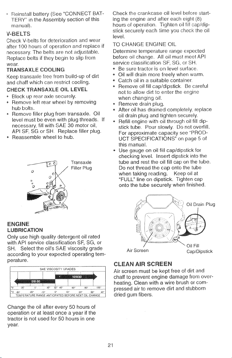
CHECK TRANSAXLE OIL LEVEL
Block up rear axle securely.
', Remove left rear wheel by removing
hub bolts.
o Remove filler plug from transaxle. Oil
level must be even with plug threads. If
necessary, fill with SAE 30 motor oil,
API SF, SG or SH. Replace filler plug.
o Reassemble wheel to hub.
Transaxle
O
O
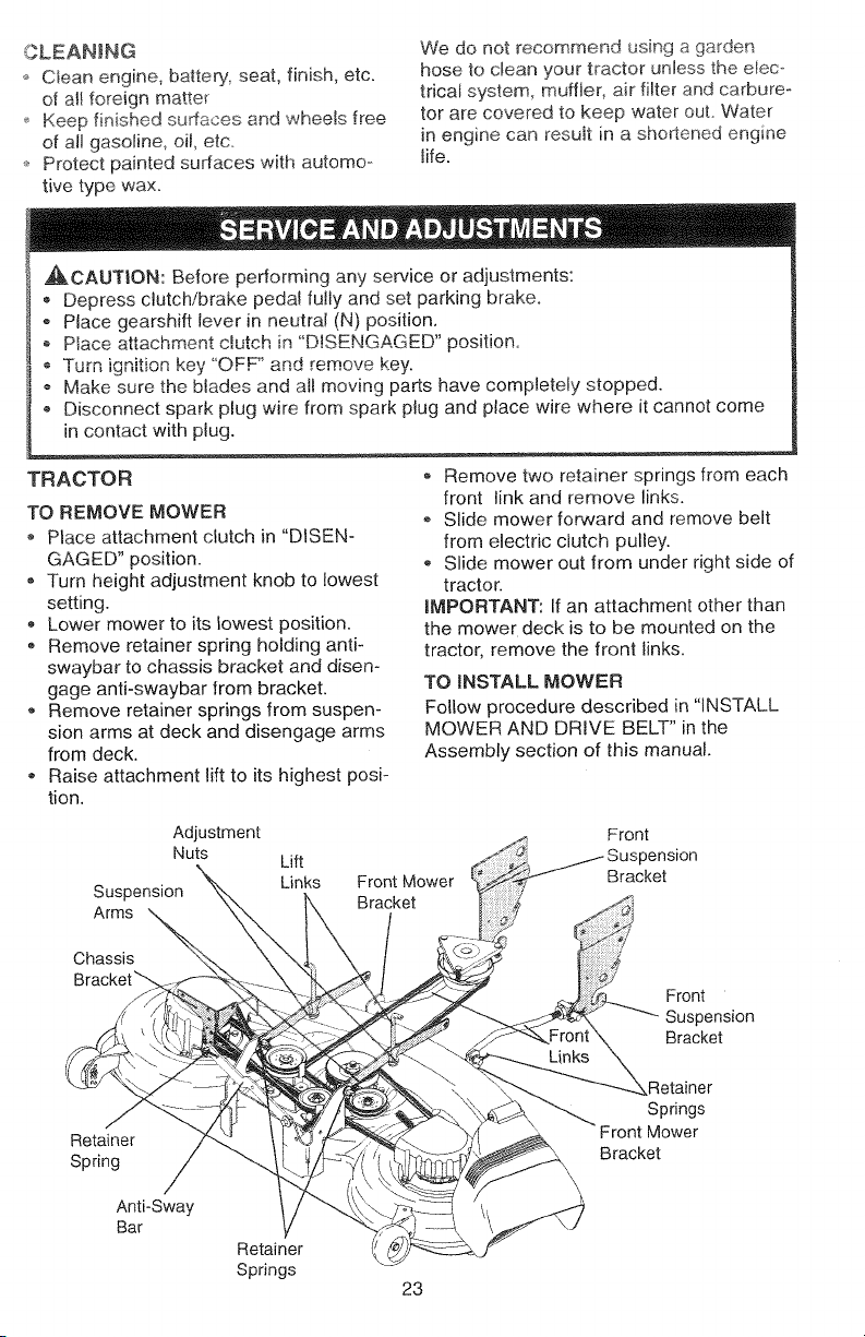
Check the crankcase oil level before start-
ing the engine and after each eight (8)
hours of operation.. Tighten oil fi!l cap/dip-
stick securely each time you check the oil
level.
TO CHANGE ENGINE OIL
Determine temperature range expected
before oi! change All oil must meet API
service classification SE SG, or SH
o Be sure tractor is on level surface
o Oil will drain more freely when warm.
,, Catch oil in a suitable container.
® Remove oil fill cap/dipstick Be careful
_ut to a,,uv-,dirt to enter the engine
when _'_'_
o Remove drain plug.
o After oil has drained completely, replace
oil drain plug and tighten securely.
,, Refill engine with oil through oil fill dip-
stick tube. Pour slowly. Do not ovedill.
For approximate capacity see 'PROD-
UCT SPECIFICATIONS" on page 5 of
this manual.
Use gauge on oil fill cap/dipstick for
checking level. Insert dipstick into the
tube and rest the oil fill cap on the tube.
Do not thread the cap onto the tube
when taking reading. Keep oil at
"FULL" line on dipstick. Tighten cap
onto the tube securely when finished.
i Filler Plug
ENGINE
LUBRICATION
Only use high quality detergent oi! rated
with API service classification SF, SG, or
SH. Select the oi!'s SAE viscosity grade
according to your expected operating tem-
perature.
SAE ViSCOSiTY GRADES
Change the oil after every 50 hours of
operation or at least once a year if the
tractor is not used for 50 hours in one
year.
Air Screen Cap/Dipstick
CLEAN AiR SCREEN
Air screen must be kept free of dirt and
chaff to prevent engine damage from over-
heating. Clean with a wire brush or com-
pressed air to remove dirt and stubborn
dried gum fibers.
21
Page 22

CLEANAiRINTAK_COOLINGAREAS
q_binsurepropercooling,makesurethe
grassscreen,coolingfins,andother
externalsurfacesoftheenginearekept
cleanatalltimes.
Every100hoursofoperation(moreoften
underextremelydusty,dirtycOnditions),
removetheblowerhousingandother
coolingshrouds.Cleanthecoolingfins
andexternalsurfacesasnecessary.Make
surethecoolingshroudsarereinstalled.
NOTE:Operatingtheenginewitha
blockedgrassscreen,dirtyorplugged
coolingfins,andorcoolingshroudsre-
movedwiltcauseenginedamagedueto
overheating.
AIRFILTER
Yourenginewillnotrunpropedyusinga
dirtyairfilter.Cleanthefoampre-cleaner
aftereven/25hoursofoperationorevery
season.Servicepapercartridgeevery
!00 hours of operation or ever':/season,
whichever occurs firsL
Service air cleaner more often under dusty
conditions.
,, Loosen knob and remove cover.
TO SERVICE PRE-CLEANER
Slide foam pre-cleaner off cartridge.
,, Wash it in liquid detergent and water.
,_ Squeeze it dry in a clean cloth. Allow it
to dry.
,, Saturate it in engine oil. Wrap it in
clean, absorbent cloth and squeeze to
remove excess oil.
TO SERVICE CARTRIDGE
Replace a dirty, bent, or damaged car-
tridge.
Cartridge
Foam
Pre-cleaner
Cartridge
Plate
Rubber
Seal
NOTE: Do not wash the paper cartridge
or use pressurized air, as this will damage
the cartridge..
o Remove nut and cartridge plate.
,, Reinstall the pre-cleaner (cleaned and
oiled) over the paper cartridge.
o Check rubber seat for damage and
proper position around stud. Replace if
necessary.
Reassemble air cleaner, cartridge ptate,
and nut.
o Reinstall air cleaner cover and secure
by tightening knob.
ENGLNE OIL F!LTER
Replace the engine oi! filter every season
or with ever,! second oi! change if the trac-
tor is used more than 100 hours in one
year
MUFFLER
Inspect and replace corroded muffler and
spark arrester (if equipped) as it could cre-
ate a fire hazard and/or damage.
SPARK PLUGS
Replace spark plugs at the beginning of
each mowing season or after every 100
hours of operation, whichever occurs first.
Spark plug type and gap setting are
shown in "PRODUCT SPECIFICATIONS"
on page 5 of this manual.
IN-LINE FUEL FILTER
The fue! filter should be replaced once
each season. If fuel filter becomes
clogged, obstructing fuel flow to carbure-
tor, replacement is required.
® With engine cool, remove filter and plug
fuel line sections.
,, Place new fuel filter in position in fuel
line with arrow pointing towards carbu-
retor.
o Be sure there are no fuel line leaks and
clamps are properly positioned.
22
Page 23
_,LEAN_N
Cleanengine,batteryseat,finish,etc.
ofallforeignmatter
Keepfinishedsu#acesandwheelsfree
ofallgasoline,oil,etc.
* Protectpaintedsurfaceswithautomo_
We do not recommend using a garden
hose to c_ean your tractor unless the elec-,
tricat system, muffler, air filter and carbure-
tor are covered to keep water ouL Water
in engine can resuit in a shortened engine
life.
tivetypewax.
A_,,CAUTION: Before performing any service or adjustments:
, Depress clutch/brake peda! fully and set parking brake.
- Place gearshift lever in neutral (N) position.
o Place attachment clutch in 'DISENGAGED" position.
-r_,,,_ignition key "OFF' and remove key.
,, Make sure the blades and a!! moving parts have completely stopped.
• Disconnect spark plug wire from spark plug and place wire where it cannot come
in contact with plug.
I
l
TRACTOR
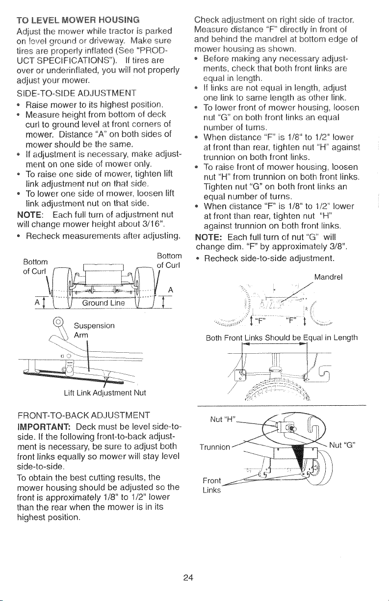
TO REMOVE MOWER
Place attachment clutch in "DISEN-
GAGED" position.
, Turn height adjustment knob to lowest
setting.
,, Lower mower to its lowest position.
, Remove retainer spring holding anti-
swaybar to chassis bracket and disen-
gage anti-swaybar from bracket.
- Remove retainer springs from suspen-
sion arms at deck and disengage arms
from deck.
® Raise attachment lift to its highest posi-
tion.
Adjustment
Nuts
Suspension
Arms
Chassis
Bracket_
Retainer
Spring
/
Anti-Sway
Bar
Retainer
Springs
Lift
Links
Front Mower
Bracket
, Remove two retainer springs from each
front link and remove links.
,, Slide mower forward and remove belt
from electric clutch pulley.
,, Slide mower out from under right side of
tractor.
mMPORTANT: If an attachment other than
the mower deck is to be mounted on the
tractor, remove the front links.
TO iNSTALL MOWER
Follow procedure described in "INSTALL
MOWER AND DRIVE BELT" in the
Assembly section of this manual.
Front
)ension
Bracket
Front
Suspension
Bracket
_Retainer
Springs
Front Mower
Bracket
23
Page 24
TO LEVEL MOWER HOUSING
Adjust the mower while tractor is parked
ors!e!e_ ground or driveway Make sure
tires are propedy inflated (See '*PROD_*
UCT SPECIFICATIONS'). If tires are
over or undennfiated, you will not properly
adjust your mower.
SIDE-TO-SIDE ADJUSTMENT
Raise mower to its highest position.
Measure height from bottom of dock
cud to ground level at front corners of
mower. Distance "A'_on both sides of
mower should be the same.
If adjustment is necessary, make adjust-
Itl_11L Ull OI1_ _lu_ u_ mower on .
.............. ly
To raise one side of mower, tighten lift
link adjustment nut on that side.
,, To lower one side of mower, loosen lift
link adjustment nut on that side.
NOTE: Each full turn of adjustment nut
will change mower height about 3/16".
o Recheck measurements after adjusting.
Bottom
oB°c°rT _-_ E_---._ n--- °fcurl
Check adjustment on right side of tractor.
Measure distance 'F' directty in front of
and behind the mandret at bottom edge of
mower housing as shown.
Before making any necessary adjust
merits, check that both front links are
equal in length_
o If links are not equal in length, adjust
one link to same length as other rink.
To lower front of mower housing, loosen
nut _G" on both front links an equal
number of turns.
When distance "F' is 1/8" to 1/2" tower
at front than rear, tighten nut *'H*'against
trunnion on both front links.
To raise front of mower housing, loosen
nut "H'* from trunnion on both front links.
Tighten nut "G" on both fronl links an
equal number of turns.
• When distance "F" is 1/8" to 1/2_lower
at front than rear, tighten nut 'H'
against trunnion on both front links.
NOTE: Each full turn of nut "G" will
change dim. "F" by approximately 3/8".
o Recheck side-to-side adjustment.
Mandrel
Suspension
Arm
Lift Link Adjustment Nut
FRONT-TO-BACK ADJUSTMENT
iMPORTANT: Deck must be level side-to-
side. If the following front-to-back adjust-
ment is necessary, be sure to adjust both
front links equally so mower will stay level
side-to-side.
To obtain the best cutting results, the
mower housing should be adjusted so the
front is approximately t/8" to 1/2" lower
than the rear when the mower is in its
highest position.
BothFront Links Should be Equal in Length
Front
Links
24
Page 25

TOREPLACEMOWERDRmVEBELT
MOWERDR_VEBELq-REMOVAL
ParktractoronalevelsudaceEngage
parkingbrake.
Removefourscrewsfromlefthand
mandrelcoverandremovecover..
o Rollbeltoverthetopoflefthandman°
dre_pulley.
o RemovebeltfromeJectdcclutchpulley.
o Removebeltfromidlerpulleys.
o RemoveanydirtorgrasscJippings
whichmayhaveaccumulatedaround
mandrelsandentireupperdecksur-
face.
oCheckprimaryidlerarmandtwoidlers
toseethattheyrotatefreely.
o Besurespringissecurelyhookedtopri-
maryidlerarmandboltinmowerhous-
ing.
MOWERDRWEBELTINSSALLAttO
oInstallbeltinbothidlers.Makesurebelt
isinbothbeltkeepersattheidlersas
shown.
,_ Install new belt onto electric clutch pul-
ley.
,, Roll belt into upper groove of left hand
mandre_ pulley.
o Carefully check belt routing making sure
belt is in the grooves correctly and
inside belt keepers.
o Reassemble _....t hand ,---'_'^'__, ,u,_, cover.
Left Hand Screws
Mandrel
Cover X_
,7
Left Hand
Mandrel
Primaqt
Idler Arm
Belt
Keepers
Idler
Pulleys
j-i_i Electric
Clutch
25
Page 26

TO REPLACE MOWER BLADE DRIVE
BELT
Park the tractor on leve_sufaceo Engage
parking brake.
Remove mower drive be_t (See "TO
REPLACE MOWER DR_VE BELT" in
this section of this manual).
Remove mower (See "TO REMOVE
MOWER" in this section of this manual}.
* Remove screws from right hand man-
drel cover and remove cover. Unhook
spring from bolt on mower housing.
Carefully roll beit off right hand mandrel
pulley_
Remove belt from center mandrel puF
Icy, idler pulley, and left hand mandrel
puiiey.
Remove any dirt or grass which may
have accumulated around mandrels and
entire upper deck surface.
LeftHand
Mandrel
Secondar
Idler Arm
Spring
Anti-Sway-Bar
Bracket
Mower Blade
Drive Belt
o Check secondary idler arm and idler to
see that they rotate freely.
Be sure spring is hooked in secondary
idler arm and sway-bar bracket.
install new belt in lower groove of left
hand mandrel pulte_; idler pulley, and
center mandrel pultey as shown.
Roll belt over right hand mandret pulley.
Make sure belt is in aH grooves properlyo
Reconnect spring to bolt in mower
housing and reinstall right hand mandrem
cover.
Reinstall mower to tractor (See
"INSTALL MOWER AND DRIVE BELT"
in the Assembly section of this manua 0.
Reassemble mower drive belt (See "TO
[3 [3 A_E R _! F_ I_/E" tZm
,,E, LA,J_. M,.,WER __,R,_,-B,-,-, in
this section of this manual).
Center
Mandrel
_dler
Pulley
Right Hand
Cover
TO ADJUST ATTACHMENT CLUTCH
The electric clutch should provide years of
service. The clutch has a built-in brake
that stops the pulley within 5 seconds.
Eventually, the intema! brake wil! wear
which may cause the mower blades to not
engage, or, to not stop as required.
Adjustments should be made by your
nearest authorized service center/depart-
ment.
o Make sure attachment clutch and igni-
tion switches are in "OFF" position.
o Adjust the three nylon Iocknuts until
space between clutch plate and rotor
measures .0!2" at all three slot loca-
tions cut in the side of brake plate.
Rotor Clutch Plate
\
Slot (3)
Nylon Locknut (3)
.0!2"
Brake Plate
NOTE: After installing a new electric
clutch, run tractor at full throttle and
engage and disengage electric clutch t0
cycles to wear in clutch plate.
TO ADJUST BRAKE
Your tractor is equipped with an adjustable
brake system which is mounted on the left
side of the transaxie.
fftractor requires more than six (6) feet
stopping distance at high speed in high-
est gear, then brake must be adjusted.
Depress clutch/brake pedal and engage
parking brake°
® Measure distance between brake oper-
ating arm and nut "A" on brake rod.
If distance is other than 1-3/4", loosen
jam nut and turn nut "A" until distance
becomes 1-3/4". Retighten jam nut
against nut "A".
o Road test tractor for proper stopping
distance as stated above. Readjust if
necessary. If stopping distance is still
greater than six (6) feet in highest gear,
further maintenance is necessary.
Contact your nearest authorized ser-
vice center/department.
26
Page 27

TOREPLACEMOTIONDRIVEBELT
ParkthetractoronlevelsurfaceEngage
parkingbrake.Foreaseofservicethere
isabe_tinstallationguidedecalonbottom
ofleftfootrest.Itisnotnecessaryto
removemower
BELTREMOVAL-
Engage parking brake (creates slack in
belt).
o Remove mower drive belt from electric
clutch pulley only (See "TO REPLACE
MOWER DRIVE BELT" in this section of
this manual).
o Roll motion drive belt off transaxle pul-
ley.
Roll _" t_we,, off, ,-,h ,_,-.Mr_,_ 1,4!_r pu!lc_y_, fh_qn
off engine pulley and front 'v-idler pulley.
o Pull belt out of all belt keepers.
BELT INSTALLATION -
o Place V part of belt into grooves on
engine pulley and front V-idler; making
sure to route belt inside of belt keepers.
, Put belt coming from V-idler above
midspan belt keeper, then onto clutch-
ing idler pulleys as shown.
o Make sure V part of belt engages '4-
idler:
Place belt around transaxle pulley_
beginning at top.
V part of belt should engage transaxle
pulley.
Place long lower section of belt through
loop in midspan belt keeper.
o Check to be sure belt is on proper side
of all belt keepers.
• Reinstall mower drive belt onto electric
clutch pulley,
IMPORTANT: Check brake adjustment,
Clutching
Idler
Clutching \ Belt
_<,_in,_ Flat Idler \ / Keeper
Pul_'e'y Above Belt \
TO ADJUST STEERING WHEEL ALiGN-
MENT
If steering wheel crossbars are not hod-
zontal (left to right) when whee!s are posi-
tioned straight forward, remove steering
wheel and reassemble per instructions in
the Assembty section of this manual.
FRONT WHEEL TOE-IN ADJUSTMENT
Front wheel toeqn is required for proper
steering operation. Toe-in was set at the
factory and adjustment should not be neco
essary. If parts in the front axle or steering
mechanism have been replaced or dam_
aged, check toe-in and adjust if necessary'.
TO CHECK TOE-IN
o Position front wheels straight ahead.
® Measure distance between wheels at
front and rear of tires (dimensions "A"
and "B").
Front dimension "A" should be 1/8" to
1/4" tess than rear dimension "B".
TO ADJUST TOE-IN
-- Loosen jam nuts at adjustment sleeves
on tie rod.
Adjust tie rod until dimension "A" is 1/8"
to 1/4" less than dimension "B".
o Tighten jam nuts securely.
FRONT WHEEL CAMBER
The front wheel camber is not adjustable
on your tractor. If damage has occurred to
affect the front wheel camber, contact your
nearest authorized service center/depart-
ment.
/
_En-gin_Twists Belt /
_, 1- _ Pullev I Keeper /
_ " t Transaxle
_ V-Idler Pulley
As Viewed from Bottom
• / AdjustmentSleeves
: XieRod
........ / ....
Jam Nuts
27
Page 28

TOREMOVEWHEELFORREPAmRS
FRONTWHEEL
oBlockupaxiesecurety.
o Removeaxlecover,retainingringand
washerstoallowwheelremoval.
,,Repairtireandreassembfe
®Replacewashersandsnapretaining
ringsecurelyinaxlegroove
,, Replaceaxlecover.
REARWHEEL
Blockrearaxlesecurely.
Removefive(5)hubboltstoallow
wheelremoval
Repairtireandreassemble.Replace
andtightenhubboltssecurely.
NOTE:Tosealtirepuncturesandprevent
flattiresduetoslowleaks,tiresealant
maybepurchasedfromyourlocalparts
dealer.Tiresealantalsopreventstiredry
rotandcorrosion.
Washers
Retaining
Ring
Axle Cover
TO START ENGINE THAT HAS A WEAK
BATTERY
,_CAUTION: Lead-acid batteries gener-
ate explosive gases. Keep sparks, flame
and smoking materials away from batter-
ies. Always wear eye protection when
around batteries.
If your battery is too weak to start the
engine, it should be recharged. If "jumper
cables" are used for emergency starting,
follow this procedure:
IMPORTANT: Your tractor is equipped
with a !2 volt negative grounded system.
The other vehicle must also be a 12 volt
negative grounded system. Do not use
your tractor battery to start other vehicles.
TO ATTACH JUMPER CABLES -
Connect each end of the RED cable to
the POSITIVE (+) terminal of each bat-
tery, taking care not to short against
chassis.
o Connect one end of the BLACK cable to
the NEGATIVE (-) terminal of fully
charged battery.
o Connect the other end of the BLACK
cable to good CHASSIS GROUND
away from fuel tank and battery.
TO REMOVE CABLES REVERSE
ORDER -
o Remove BLACK cable first from chassis
and then from the fully charged battery.
o Remove RED cable last from both bat-
teries.
"Positive" (+) "Negative"(-)
L.H. Panel [ _il
Bolt "_-'--.._
¢ " /
<_...... /
TO REPLACE HEADLIGHT BULB
" Raise hood.
,, Pull bulb holder out of the hole in the
backside of the gril!.
,, Replace bulb in holder and push bulb
holder securely back into the hole in the
backside of the grill
o Close hood.
INTERLOCKS AND RELAYS
Loose or damaged wiring may cause your
tractor to run poorly, stop running, or pre-
vent it from starting.
,, Check wiring. See electrical wiring dia-
gram in the Repair Parts section of this
manual.
TO REPLACE FUSE
Replace with 30 amp automotive-type
plug-in fuse. The fuse holder is located
behind the dash.
formed by an authorized engine manufac-
turer's service outleL
TO REMOVE HOOD AND GRILL
ASSEMBLY
o Raise hood.
,, Unsnap headlight wire connector.
* Stand in front of tractor. Grasp hood at
sides, tilt toward engine and lift off of
tractor.
To replace, reverse above procedure.
Hood
@ Headlight
Wire
Connector
28
Page 29

ENGINE
Maintenance,repair,orreplacementofthe
emissioncontrotdevicesandsystems,
whicharebeingdoneatthecustomers
expense,maybeperformedbyanynon-
roadenginerepairestablishmentorindi-
vidual.Warrantyrepairsmustbeper-
formedbyanauthorizedenginemanufac-
turer'sserviceoutlet.
TOADJUSTTHROTTLECONTROL
CABLE
Thethrottlecontrolhasbeenpresetatthe
factoryandadjustmentshouldnotbenec-
essary.Checkadjustmentasdescribed
u_,,J,,vbe,orelooseningcab,e.!fadjust-
mentisnecessary,proceedasfollows:
,,Withenginenotrunning,movethrottle
controllevertofastposition.
oCheckthatspeedcontrolleveris
againststopscrew.Ifitisnot,loosen
casingclampscrewandpullthrottle
cableuntilleverisagainstscrew.
Tightenclampscrewsecurely.
Idle Fuel
Adjusting Idle Speed
Needle Adjusting Screw
Control
Cable
i]_i i _¸¸_ '
..... _,I I_iliilil,ii!, i_lii_ill _ .........
• __ ! , ,,,! ,_ ¢
, I , jq
I, i _ _iII _i /
]Li/,,,!,I!,! ,,,,(I
I_-/_ LuU|IU{J[IJLI[JUii[]! l!illjUg; L_ [
Stop Screw-" _ /
TO ADJUST CHOKE CONTROL
The choke control has been preset at the
factory and adjustment should not be nec-
essary, check adjustment as described
below before loosening cable. If adjust-
ment is necessary, proceed as follows:
o With engine not running, move choke
control (located on dash panel) to full
choke position.
Clamp Screw Choke Control Cable
o Remove air cleaner cover fitter and car-
tridge plate to expose carburetor choke
(See "AIR F_LTER" in the Customer Reo
sponsibitities section of this manual).
o Choke shouid be dosed. If it is not,
loosen casing clamp screw and move
choke cable untiJ choke is completely
closed. Tighten casing clamp screw se-
curely.
o Reassemble air cleaner.
Closed for Full
Choke , q,
TO ADJUST CARBURETOR
The carburetor has been present at the
factory and adjustment should not be neco
essary. However, minor adjustment may
be required to compensate for differences
in fuel, temperature, altitude or load. If the
carburetor does need adjustment, proceed
as follows:
In general, turning the adjusting needles
in (clockwise) decreases the supply of fuel
to the engine giving a leaner fuel/air mix-
ture. Turning the adjusting needles out
(counterclockwise) increases the supply of
fuel to the engine giving a richer fuel/air
mixture.
RMPORTANT: Damage to the needles
and the seats in carburetor may result if
screw is turned in too tight.
PRELIMINARY SETTING
® Be sure you have a clean air filter, and
the throttle control cable is adjusted
properly (see "TO ADJUST THROTTLE
CONTROL CABLE" in the Service and
Adjustments section of this manual).
With engine off turn idle fuel adjusting
needle in (clockwise) closing it finger
tight and then turn out (counterclock-
wise) 1 turn.
29
Page 30

FBNALSETTING
Startengineandallowtowarmforfive
minutes.Makefinaladjustmentswith
enginerunningandshifb'motioncentro_
leverinneutrat(N)position.
Thehighidleissetatthefactoryand
cannotbeadjusted.
Idle - With throttle control
lever in slow position, engine should
idle at 1200 RPM tf engine idles too
stow or fast, turn idle speed adjusting
screw in or out until correct idle is
attained.
o Idlerue! needle Se_ - With throttle
contro_ lever in slow position, turn id!e
fuet adjusting needle in (clockwise) until
engine speed decreases and then turn
out (counterclockwise) approximately
3/4 turn to obtain the best low speed
performance.
. Recheck idle speed. Readjust if neces-
sary.
ACCELERATION TEST o
Move throttle contro_ lever from stow to
fast position. If engine hesitates or dies,
turn idle fuel adjusting needle out
(counterclockwise) 1/8 turn. Repeat test
and continue to adjust, if necessary,
until engine accelerates smoothly.
High speed stop is factory adjusted. Do
not adjusbdamage may result.
_MPORTANT: Never tamper with the
engine governor, which is factory set for
proper engine speed Overspending the
engine above the facory high speed set°
_,_.,,_ can be dangerous, if,you think the
_ i _......... high speed needs_,,g,n._ _....... d
adjusting, contact your nearest authorized
service center/department, which has
proper equipment and experience to make
any necessary adjustments.
30
Page 31

Immediatelyprepareyourtractorforstor-
ageattheendd the season or if the trac-
tor will not be used for 30 days or more.
_CAUT_ON: Never store the tractor with
gasoline in the tank inside a building
where fumes may reach an open flame or
spark. Allow the engine to cool before stor-
ing in any enclosure.
TRACTOR
Remove mower from tractor for winter
storage. This will allow you to clean it thor-
ough}y. Remove all did, grease, !eaves,
etc. Store in a clean, dry area.
* Clean entire tractor (See "CLEANING"
in the Maintenance section of this man-
ual).
Inspect and replace belts, if necessary
(See belt replacement instructions in the
Service and Adjustments section of this
manual).
Lubricate as shown in the Maintenance
section of this manual.
Be sure that all nuts, bolts and screws
are securely fastened, inspect moving
parts for damage, breakage and wear.
Replace if necessary.
Touch up all rusted or chipped paint sur-
faces; sand lightly before painting.
BATTERY
. Fully charge the battery for storage.
After a period of time in storage, battery
may require recharging.
* To help prevent corrosion and power
leakage during !ong periods of storage,
battery cables should be disconnected
and battery cleaned thoroughly (see
"TO CLEAN BATTERY AND TERMI-
NALS" in the Maintenance section of
this manual).
After cleaning, leave cables disconnect-
ed and place cables where they cannot
come in contact with battery terminals.
- If battery is removed from tractor for
storage, do not store battery directly on
concrete or damp surfaces.
ENGINE
FUEL SYSTEM
IMPORTANT: It is important to prevent
gum deposits from forming in essential
fuel system parts such as carburetor, fuel
filter, fuel hose, or tank during storage.
Also, experience indicates that alcohol
Mended rued (ca!led gasohol or using
ethanol or methanol) can attract moisture
which leads to separation and formation of
acids during storage. Acidic gas can dam-
age the fuel system of an engine while in
storage.
- Drain the fuel tank.
Start the engine and let it run until the
fuel lines and carburetor are empty.
- Never use engine or carburetor cleaner
products in the fuel tank or permanent
damage may occur.
• Use fresh fuel next season.
NOTE: Fuel stabilizer is an acceptable
alternative in minimizing the formation of
fuel gum deposits during storage. Add sta-
bilizer to gasoline in fuel tank or storage
container. Always follow the mix ratio
found on stabilizer container. Run engine
at least 10 minutes after adding stabilizer
to allow the stabilizer to reach the carbure-
tor. Do not drain the gas tank and carbure-
tor if using fuel stabilizer.
ENGINE OIL
Drain oil (with engine warm) and replace
with clean engine oil. (See "ENGINE" in
the Maintenance section of this manual).
CYLINDER(S)
= Remove spark plug(s).
Pour one ounce of oil through spark plug
nole(s) into cylinder(s).
Turn ignition key to "START" position for
a few seconds to distribute oi!.
• Replace with new spark plug(s).
OTHER
Do not store gasoline from one season
to another.
Replace your gasoline can if it starts to
rust. Rust and/or dirt in your gasoline will
cause problems.
- If possible, store your tractor indoors
and cover it to give protection from dust
and dirt.
Cover your tractor with a suitable protec-
tive cover that does not retain moisture.
Do not use plastic. Plastic cannot
breathe, which allows condensation to
form and cause your tractor to rust.
IMPORTANT: Never cover tractor while
engine and exhaust areas are still warm.
31
Page 32

TROUBLESHOOTING CHART
PROBLEM
Wi!] not start
CAUSE
o Out of fue!.
Engine not "CHOKED"
properly.
o Engine llooded.
Bad spark plug.
Dirty air filter.
* Dirty fuel filter.
Water in fuel.
Loose or damaged wiring,
* Carburetor out of adjust-
ment.
Engine valves out of
adjustment.
CORRECTION
Fill fue_ tank,
See "TO START ENGINE" in
Operation section
o Wait severat minutes before
attempting to start.
Replace spark plug.
C_ean/rep_ace air fi_tero
Replace fuel filter.
Drain fuel tank and carbure-
tor, refill tank with fresh
gasoline and replace fue! f!!-
ter.
Check all wiring
o See "To Adjust Carburetor''
in Service and Adjustments
section.
Contact an authorized ser-
vice center.
Hard to start
Engine will not turn
over
Engine clicks but
will not start
Dirty air filter:
Bad spark plug.
Weak or dead battery.
,, Dirty fuel filter.
® Stale or dirty fuel.
Loose or damaged wiring.
Carburetor out of adjust-
ment.
Engine valves out of
adjustment.
, Clutch/brake pedal not
depressed
Attachment clutch is
engaged
Weak or dead battery.
Blown fuse.
Corroded battery termi-
nals.
, Loose or damaged wiring,
Faulty ignition switch.
o Faulty solenoid or starter.
Faulty operator presence
Weak or dead battery.
Corroded battery termi-
na}s.
Loose or damaged wiring.
Faulty solenoid or starter.
32
Clean!replace air filter.
Replace spark plug
Recharge or replace battery.
Replace fuel filter.
Drain fuel tank and refi!l with
fresh gasoline,
Check all wiring.
, See "To Adjust Carbureto¢'
in Service and Adjustments
section,
• Contact an authorized seto
vice center.
Depress clutch/brake pedal.
Disengage attachment
clutch.
Recharg, or replace battery.
Replace fuse.
Clean battery terminals.
Check all wiring,
ChecWreplace ignition
switch_
o ChecWreplace solenoid or
starter.
Contact an authorized ser-
vice center.
• Recharge or replace battery.
Clean battery terminals.
o Check all wiring.
• ChecWreplace solenoid or
starter.
Page 33
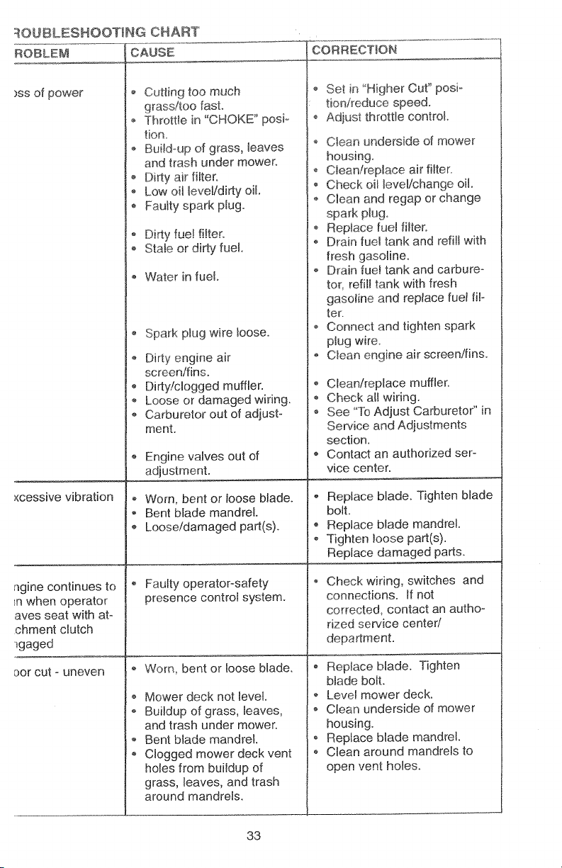
ROUBLESHOOT_NG CHART
ROBLEM CAUSE
)ss of power
o Cutting too much
grasdtoo fast.
o Throttle in "CHOKE" posio
fion_
o Build_up of grass, leaves
and trash under mower.
- Dirty air filter.
o Low oil level/dirty oil
Faulty spark plug.
Dirty fue! filter.
o Stale or dirty fue!.
,, Water in fuel.
Spark plug wire loose.
Dirty engine air
screen/fins.
e
Dirty/clogged muffler.
e
Loose or damaged wiring.
Carburetor out of adjust-
ment.
Engine valves out of
adjustment.
×cessive vibration
,, Worn, bent or loose blade.
Bent blade mandrel.
_, Loose/damaged part(s).
CORRECTION
e
Set in "Higher Cut" posi°
tionireduce speed°
¢
Adjust throttle control
e
Cfean underside of mower
housing_
e
Clean!replace air filter
e
Check oil level/change oil.
e
Clean and regap or change
spark p_ug.
e
Replace fuel filter.
Drain fuel tank and refill with
fresh gasoline.
@
Drain fuel tank and carbureo
tot refill tank with fresh
gasoline and replace fuel fil-
ter.
Connect and tighten spark
plug wire
Ctean engine air screen!fins.
o Clean/replace muffler.
o Check all wiring.
See "To Adjust Carbureto¢' in
Service and Adjustments
section.
o Contact an authorized ser-
vice center.
Replace blade. Tighten blade
bolt.
Replace blade mandrel.
Tighten loose part(s).
Replace damaged parts.
ngine continues to
n when operator
aves seat with at-
chment clutch
-_gaged
cot cut - uneven
Faulty operator-safety
presence control system.
Worn, bent or loose blade.
Mower deck not level.
Buildup of grass, leaves,
and trash under mower.
Bent blade mandrel.
Clogged mower deck vent
holes from buildup of
grass, leaves, and trash
around mandrels.
33
Check wiring, switches and
connections. If not
corrected, contact an autho-
dzed service center/
department.
o Replace blade. Tighten
btade boit.
Level mower deck.
o Clean underside of mower
housing.
o Replace blade mandrel.
o Clean around mandrels to
open vent holes.
Page 34
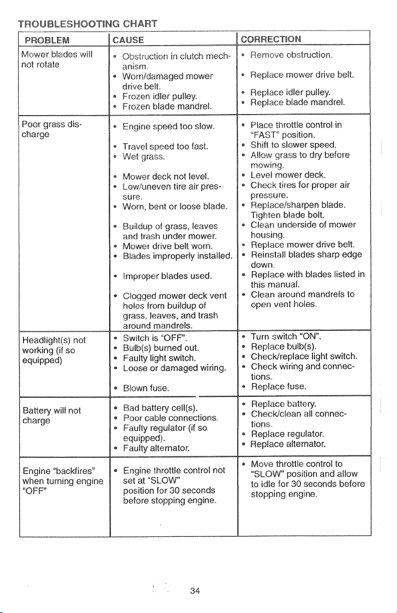
TROUBLESHOOTING CHART
CAUSEPROBLE_._
Mower blades will
not rotate
o Obstruction in ciutch mecho
anism
o Worn/damaged mower
drive belt.
Frozen idler pulley.
o Frozen blade mandrel.
CORRECTION
_" Remove _-_" _ ._ n_us_ru_4_O. _.
o Replace mower drive belt.
o Replace idler pulley.
RepJace blade mandrel.
Poor grass dis-
charge
_ht(s) not
working (if so
equipped)
Battery will not
charge
Engine "backfires"
when turning engine
"OFF"
Engine speed too stow.
o Travel speed too fast.
Wet grass.
o Mower deck not level.
Low/uneven tire air pres o
sure
Worn, bent or loose blade.
Buildup of grass, leaves
and trash under mower.
Mower drive belt worn.
Blades improperly installed.
Improper blades used.
Clogged mower deck vent
holes from buildup of
grass, leaves, and trash
around mandrels.
Switch is "OFF".
* Bulb(s) burned out.
Faulty light switch.
Loose or damaged wiring.
o Blown fuse.
o Bad battery cell(s).
® Poor cable connections.
• Faulty regulator (if so
equipped).
Faulty alternator.
Engine throttle control not
set at "SLOW"
position for 30 seconds
before stopping engine.
Place throttle control in
"FAST '_position.
Shift to slower speed.
Allow grass to dry before
mowing.
* Levet mower deck.
Check tires for proper air
pressure.
o Replace/sharpen blade.
Tighten blade bolt.
Clean underside of mower
housing.
o Replace mower drive belt.
Reinstall blades sharp edge
down.
Replace with blades listed in
this manual.
Clean around mandrels to
open vent holes.
Turn switch "ON".
• Replace bulb(s).
,, Check/replace light switch.
, Check wiring and connec-
tions,
Replace fuse.
e
Replace battery.
ChecWclean all connec-
tions
Replace regulator.
Replace alternator.
Move throttle control to
"SLOW" position and allow
to idle for 30 seconds before
stopping engine.
', 34
Page 35
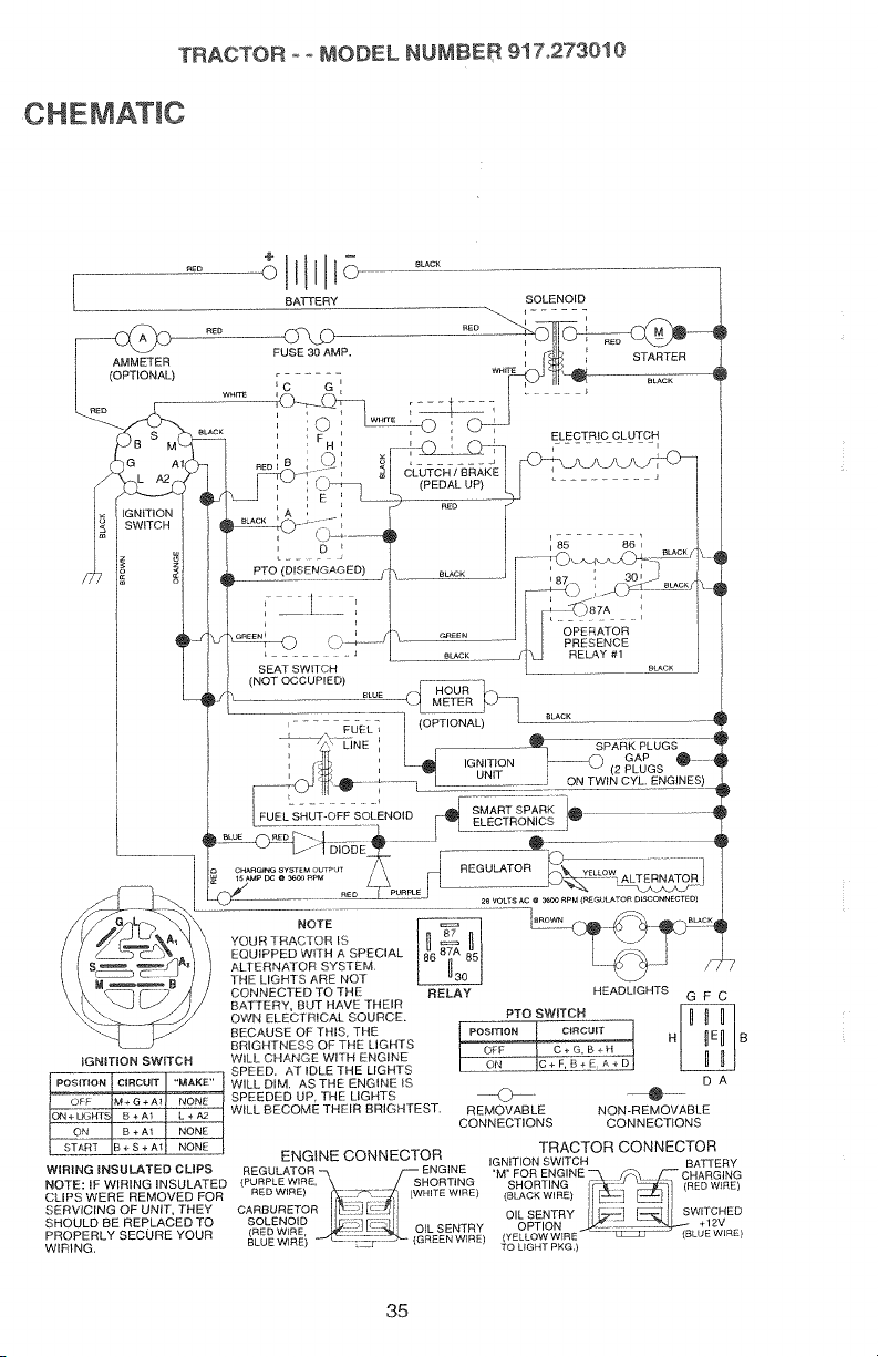
CHEMAT!C
I AMMETER
I (OPTIONAL)
TRACTOR ++MODEL NUMBER 917.2730t0
BECAUSE OF THIS. THE
IGNITION SWITCH WILL CHANGE WITH ENGINE
WIRING INSULATED CLIPS
NOTE: IF WIRING iNSULATED
CUPS WERE REMOVED FOR
SERVICING OF UNIT, THEY
SHOULD BE REPLACED TO
PROPERLY SECURE YOUR
WIRING.
BRIGHTNESS OF THE LIGHTS
SPEED. AT IDLE THE LIGHTS
SPEEDED UP, THE LIGHTS
WILL BECOME THEIR BRIGHTEST.
WILL DIM. ASTHE ENGINE _S
ENGINE CONNECTOR
REGULATOR -_ F-- ENGINE "M" FOR ENGINE _ /_ f-- CHARGING
(PURPLEWIRE,\ / SHORTING SHORTING _,_ _ _ (REDWIRE}
CARBURETOR_::_I _:_11_L ;] [;- !_il OILSENTRYoPTION II _'::1-.] _, -- +12',,_] II SWITCHEDSOLENOID r::::: _ :
,_r,w_e O+LSENTRY ..>¢_-:::_uE_,,,_)
BL_IE WIRE' {GREEN WIRE) {YELLOW WIRE
) ......._ TO LIGHT PKG.)
35
TRACTOR CONNECTOR
IGNITION SWITCH BATTERY
Page 36
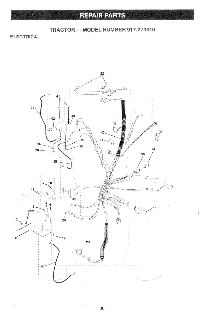
ELECTRICAL
TRACTOR ooMODEL NUMBER 917o273010
22
40
20
33
3o /
//
_.-/....so
' 36
Page 37
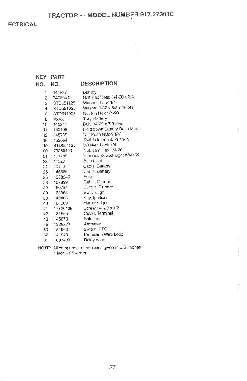
oECT'R_CAL
KEY
NO.
1
2
3
4
6
8
lO
11
12
16
19
20
21
22
24
25
26
28
29
3o
33
40
41
42
43
45
50
52
81
NOTE:
TRACTOR o° MODEL NU MBER; 9!7o2730! 0
PART
NO. DESCRIPTION
144927 Battery
74760412 Bolt Hex Head I/4 20 x 3/4
STD551125 Washer rock 1/4
STD551025 Washer 9/32 x 5/8 x 16 Ga
STD541025 Nut Fin Hex 1/4-20
7603J Tray, Battery
145211 Bolt 1/4-20 x 7.5 Zinc
150109 l-iold down Battery Dash Mount
145769 Nut Push Nylon 1/4"
153664 Switch interlock Push-in
STD551125 Washer Lock 1/4
73350400 Nut Jam Hex 1/4-20
161785 Harness Socket Light W/4152J
4152J Bulb Light
4014J Cable, Battery
146686 Cable. Battery
108824X Fuse
157899 Cable, Ground
160784 Switch Plunger
163968 Switch, Ign
140403 Key, Ignition
164069 Harness Ign.
17720408 Screw 1/4-20 x 1/2
131563 Cover, Terminal
145673 Solenoid
122822X Ammeter
154963 Switch, PTO
141940 Protection Wire Loop
109748X Relay Asm.
All component dimensions given in U.S. inches
1 inch = 25.4 mm
37
Page 38
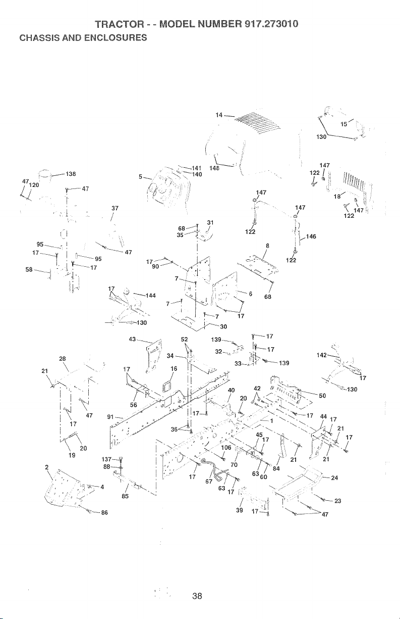
G_SS_S At_O_cLOSU_S
_B
Page 39

TRACTOR ooMODEL NUMBER 917°2730i0
HASSIS AND ENCLOSURES
EY PART KEY PART
Co NO. DESCR_PT|ON NO. NO.
t !50253 Rail, Frame RH 50 !52728
2 140506 Drawbar, Gt 52 STD541431
4 73800700 Nut, Lock He× 7/16 Unc 56 t 55.914
5 163976 Dash Stealth YTGT 2 Cyl 57 73640400
6 15788,2 Dash, Lower Vgt One Piece 58 137113
7 !720408 Screw, Thd Cut 1/4-20 x 1/2 60 17490620
8 145166 Support, Battery 63 19131614
14 161023X558 Hood #3m, Pnt Stealth YTGT 67 156973
15 160568 Lens Asm Headlight Bar Stealth 68 17490508
16 121794X Cover, Access 70 137159
17 17490612 Screw, Thdrol 3/8-16 x 3/4 84 142992
18 150564X558 Grille 85 144911
19 19131312 Washer 13/32 x 13/16 x 12 G& 86 74760716
20 STD523710 Bolt, Fin Hex 3/8-18 x 1 88 STD551143
21 STD541437 Nut Crowntock 3/8-16 Unc
23 17490616 ScrewThdrol 3/8-!6 x 1Ty-Tt 90 STD551237
24 145243X558 Footrest RH
28 ! 45244X558 Footrest, LH 91 156586
30 145051 X014 Saddle, SIkscr Vgt 95 105531X
3t 161419 Brace, Supt 1-pc VGT Steering 106 138776
32 161327 Bracket, Pivot Chassis Lh
33 161326 Bracket, Pivot Chassis Rh 120 19131616
34 142131 Bracket, Engine Support Rear 122 161464
35 19111116 Washer 11/32 x 11/16 x 16 Ga. 130 17521312
36 74780512 Bolt, Fin Hex 5/16-18 x3/4 137 74780716
37 16-3981X558 Fender YTGT PNT WO/SH Cup 138 163975
39 136961 Bracket, Axle Front 140 163806
40 156111 Bracket, Support Axle/Engine 141 163805
42 72140608 Bolt, Carriage 3/8-16x 1 142 161897
43 136939 Bracket Spnsn Front Lh 144 161900
44 136940 Bracket, Spnsn Front Rh 146 161237
45 154913 Bracket Asm., Susp Chassis Rh 147 162967
47 17490608 Screw ThdroL 3/6-16xl/2 148 164655
558 139 161330
NOTE:
All component dimensions given in U.S. inches
1 inch = 25.4 mm
DESCRIPT_ON
Bracket_ Chassis Front
Nut, Crownlock 5/16-18 Unc
Bracket Aem, Susp Chassis Lh
Nut, Keps, BIk Hex 1/4o20 UNC
Bracket Asm, Fender
Screw Thdrot. 318-16 x 1-1/4
Washer 13/32 x 1 x 14 Ga.
Guide, Belt Gear Drive
Screw ThdroL 5/16-18 x I/2
Guide, Bett Mid Span
Stop, Over Center Mower
Bracket, Support Transaxle
Bolt Fin Hex 7/16-14 UNC x 1
Washer, Lock Hvy Hlcl Spr
7/!6
Washer, Lock External Tooth
3/8
Rail, Frame Lh
Push Nut, Nylon
Screw, Thdrol Hex Head Zinc
Mwr
Washer 13/32 x 1 x 16 Ga.
Screw Hex Wshd 8-18 x 7/8
Screw Sltd H Hd W/TIn Washer
Bolt Fin Hex 7/16-14 x 1 Gr. 5
Cupholder YTGT
Bolt Shoulder 5/16-18 TT
Magnet Stealth YTGT
Striker Plate Stealth YTGT
Bracket Dash Stealth Rh
Bracket Dash Stealth Lh
Duct, Hood Heat
Fastener Nut Pal
E_rusion Bumper
39
Page 40
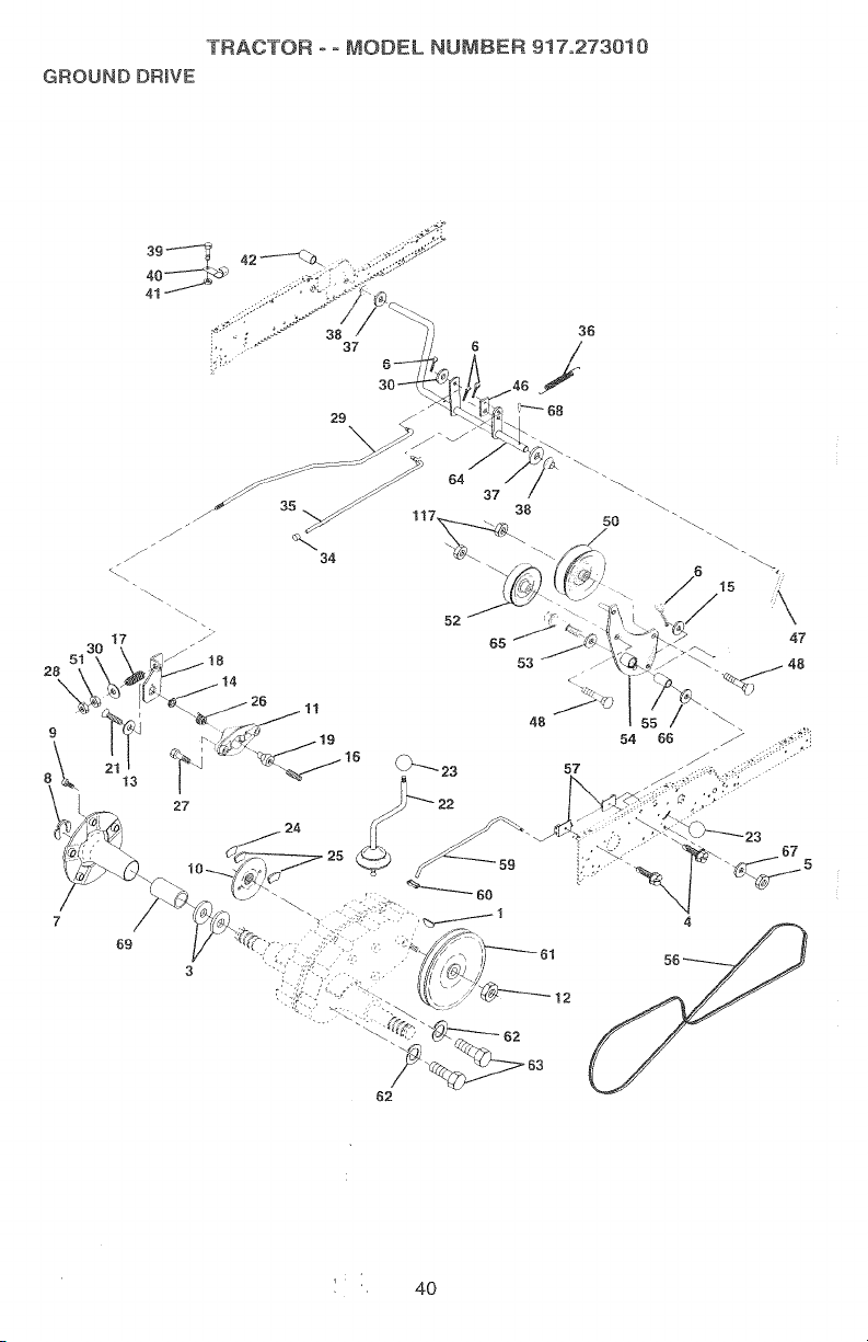
TRACTOR-oMODELNUMBER9i7o273010
GROUNDDRmVE
f/
//j
30
51
36
/
i_ 68
37
38 50 "\_
52
48
27
69
62
54 66
57
67
4
i 4O
Page 41

"TRACTOR o- MODEL NUMBER: 917.273010
ROUND IOR_VE
EY PART KEY PART
O. NO. DESCRIPT!ON NO. NO°
1 9858M! Key, Woodruff 36 149412
3 7563R Washer Thrust, Axle 37 121749X
4 17490508 Screw Thdrol 5/16-18 x 3/4 38 150035
5 STD541437 Nut, Crownlock 3/8-16 39 74321016
6 STD561210 Pin, Cotter 40 5304J
7 149176 Wheel. Hub Assembly 41 73661000
8 12000034 Klip, Ring 42 8883R
9 ! 40080 Bolt Hub 46 145170
10 142509 Disc, Brake 47 138228
11 136927 Yoke, Brake Disc 48 72110612
12 73750800 Nutlock !/2°20 Unf
!3 139419 Washer. Special 50 131494
14 138901 Bushing 51 STD541437
15 STD551037 Wahser !3/32 x 13/16 x 16 Ga. 52 139123
16 143012 Set_Screw 1/4-28 x 3/4 53 207J
17 126909X Spring 54 161590
18 137104 Lever, Brake 55 105706X
19 136926 Cam, Brake Disc 56 137153
21 23260412 Screw, Flat Head 1/4-28 x 3/4 57 141756
22 633A109 Gearshift, Lever Assembly 59 122253X
23 106932X Knob 60 122268X
24 136925 Support, Puck Brake 6t 137524
25 136923 Puck, Brake Top 62 STD551!43
26 137552 Spring, Return 63 74760720
27 !7490528 Screw, Hex Wsh Thd. 64 154752
28 73350600 Nut, HexJam 3/8-16 66 140296
29 137213 Brake, Rod 67 19131312
30 19131616 Washer 13/32 x ! x 16 Ga. 68 5142H
34 124236X Cap, Plunger 69 136327
35 137648 Rod, Parking Brake 117 73900600
5/16-18 x 1-3/4 65 67609
NOTE: All component dimensions given in U.S. inches
1 inch = 25.4 mm
DESCRIPTION
Spring, Drive Ground
Washer 25/32 x 1-1/4 x 16 Ga.
Nyliner
Screw, Fin. #10-24 x 1
Actuator, Interlock Switch
Locknut #!0-24
Cover, Pedal
Retainer, Spring
Clutch Rod
Bolt, Carriage 3/8-16 x I-I/2
Gn5
Pulley, Idler, Flat
Nut, Crownlock 3/8-16 DNC
Pulley, Idler, Grooved
Washer; Hardened
Clutch Arm Assembly
Bearing, Idler
V-Belt
Bracket. Shift Rod, Hi_Lo
Shift Rod, Hi-Lo
Spring Ctip, Connecting Link
Pulley, Transaxle
Washer. Lock 7/16
Bott, Fin He× 7/16-14 x 1-1/4
Shaft, Clutch/Brake Pedal
Bolt, Shoulder
Washer, Hardened
Washer. Flat
Pin, Roll
Hub, Cover
Nut, Lock Pig. 3/8-16 Unc
41
Page 42

STEERING "_MBLy_^^_TRACTOR _ _MODEL HUMBFER
33
28
917.2730! 0
/
J
/
Page 43

TRACTOR - = MODEL NUMBEP< 9!7,273010
TEERWNG ASSEMBLY
KEY PART
NO. NO. DESCRiPTiON
1 159944
2 137094
3 6855M
4 161849
5 161848
8 6266H
7 t21748X
8 12000029
9 !21232X
10 74781044
11 136518
12 73901000
13 121749X
14 STD551137
15 STD.541537
16 145103
17 137347
18 137155
i9 156011
20 163887
21 159945
22 155105
23 152927
25 STD523710
26 159946
27 3366R
28 17490612
29 104239X
3O 120OOO34
3! 138J36
32 1911161O
33 STD551131
34 STD523!07
35 138059
36 137156
37 73360600
38 109850X
39 73700600
40 109851X
41 155246
42 17490508
44 16O135
45 19132411
NOTE:
Wheel, Steering
Axle Asm., Front
Fitting, Grease
Spindle Asm, LH
Spindle Asm., RH
Bearing, Race Thrust Harden
Washer 25/32 x 1-5/8 x 16 Ga.
Rng, K!ip #T5304-75
Cap, Spindle
Bolt, Fin Hex 5/8.11 x 2-3/4
Spacer Bearing Axle Front
NuL Lock Flange 5/8ql Unc
Washer 25/32 x 1-1/4 x 16 Ga.
Washer Lock Hvy Hlcl Spr 3/8
Nut, Lock Center 3/8-24 UNF
Shaft Asm. Steering
Rod Asm. Tie Ball J Ball Vgt (Inc. Key No. 36-40)
Draglink, Ball Joint Solid Vgt
S_ppor_ Asm. Steering Vgt
Boot, Steering
Adapter, Wheel Steering
Bushing, Strg. BIk
Screw
Bolt, Fin Hex 3/8-16 x 1 GE 5
Cap, Wheel Steering
Bearing, Col. Strg.
Screw, Thrdrol 3/8-16 x 3/4
Bearing, Flange
Ring, Klip Truarc #5304-75
Bushing, Nyliner Snap
Washer 11/32 x 1 x 10Ga.
Washer, Lock Hvy HIcl Spr 5/16
Bolt, Hex Hd 5/16-18 x 3/4
Gear, Sector Steering
Tie Rod
Jam Nut RH Thread
Joint Asm, Ball RH Thread
Jam Nut LH Thread
Joint Asm. Ball LH Thread
Bracket Switch Interlock VGT 97
Screw Thdrol 5/16-18 x t/2 Tyt
Extension, Steering
Washer 13/32 x 1-1/20 x 11Ga.
Alt component dimensions given in U.S. inches
1 inch = 25.4 mm
43
Page 44

ENGINE
22 _j,
JY
TRACTO_ ° . MODEL NUMBER 917.273010
2
\
/ .P-
2O
44
42
43
33
54
4_
38
29
40
Page 45

NGINE
TRACTOR_-tv]ODEL NUMBER; 9! 7.273010
KEY PAR]"
NO, NO. DESCRiPTiON
1 Engine (See Breakdown)
2 161062 Muffler Side !-!/8" 98
5 18200300 Elbow STD 90 Degree 3/8 - 18 NPT
7 151396 Muffler Asm Guard
8 121361X Pulley V-Idler
9 150828 KeeperAsm. Belt Engine
10 105432X Bushing
11 140923 Clutch Electric
I2 143996 Pulley Engine VGT Elect Clutch
15 151346 Tank Fuel Rear 3.50 Yt/Gt 96
16 109227X Pad Spacer
17 106082X Pad Spacer
!8 161493 Cap Asm Fuel W/Gauge
19 13290300 Plug Oil Drain (Order From Engine
20 164067 Control Throttle
21 17521312 Screw SLTD Hex HD W/Pin Washer
22 164415 Control Choke
24 STD551237 Washer Ext Tooth 3/8
25 73920600 Nut Keps 3/8 - 24 UNF
26 3645J Bushing
27 139277 Stem Tank Fuel
28 7834R Fuel Line
29 ! 32920 Spark Arrester Kit
33 STD541437 Nut Lock Hex w/Ins. 3/8 - 16
37 123487X Clamp Hose
38 74780624 Bolt Fin Hex 3/8 - 16 x 1-1/2
39 17490636 Screw TT 3/8-!6 x 2-1/4 UNC
40 17490664 Screw "F[ 3/8-16 x 4 UNC
41 126197X Washer 1_1/20D X 15/32 ID X .250
42 STD55!143 Washer Lock 7/16
43 150280 Bolt Hex 7/16 - 20 X 4 - 1/4 Ga 5
45 128861 Nut Flange 1/4-20 Starter Nut
47 142040 Spacer Engine
48 19132007 Washer 13/32 x 1-1/4 x 7 Ga.
51 161230 Manifold Pipe VGT CV 1-1t8"
54 19131414 Washer Flat 13/32 x 7/8 x 14 Ga.
55 13280336 Nipple Pipe 4-1/2
65 19131614 Washer 13/32 x 1 x 14 Ga,
74 162295 Elbow Street Brass
76 17490612 Screw Thdrol 3/8-16 x 3/4 Ty-TT
77 19131316 Washer 13/32 x 13/16 x 16 Ga.
NOTE: All component dimensions given in U.S. inches
1 inch = 25.4 mm
Kohier Model No. CV20S-65551
Manufacturer)
45
Page 46

SEAT ASSEMBLY
TRACTOR- ° MODEL NUMBER 917.273010
KEY
PART KEY PART
NO.
NO. DESCRIPTION NO. NO.
1
140124 Seat 14 72050412
2
140551 Bracket, PivotSeat 15 121249X
3
140675 Strap, Fender 16 123740X
4
127018X Bolt, Shoulder 5/16-18 x .62 17 123976X
5
145006 Clip, Push in, Hinged 18 19171912
6
STD541437 Nut, Crownlock 3/8-16 Uric
7
124181X Spring, Seat Cprsn 19 120068X
150176 Bolt 5/16-18 Unc x 3/4.w/Seres 20 124238X
8
lO
155925 Pan, Seat 21 153236
12
121246X Bracket, Mounting Switch 22 STD541431
13
!21248X Bushing, Snap
NOTE: All component dimensions given in U.S. inches
', 46
22
21
1 inch = 25.4 mm
DESCREPTnON
Bolt, Carriage 1/4-20 X 1-1/2
Spacer, Split
Spring, Cprsn
Nut, Lock 1/4 Lge Fig Gr. 5
Washer 17/32 x 1-3/16 x 12
Ga.
Knob, Seat 1/2-13 Unc
Cap, Spring Seat
Bolt, Shoulder 5/16-18
Nut, Crownlock 5/16-18 Unc
Page 47

_CALS
TRACTOR ooMODEL NU MBER: 917o2730!0
16
/
I
PART
NO.
1
163265
2
164085
3
163916
4
163917
5
149516
6
133644
7
163210
9
163204
10
156439
1!
4900J
DESCR!PT.tON NO. NO.
Decal, Dash Panel 12 146047
Decal, Dash 14 160397
Decal, Hood, Craftsman, RH 18 164065
Decal, Hood, Craftsman, LH 19 138047
Decal, Battery DNGR/PSN 21 163203
ENG Asm 23 106202X
Decal, Maintenance - - 138311
Decal, Fender
Decal, Fender, Craftsman - - 157199
Decal, Fender Danger - - 163940
Decal, Clutch/Brake - - 163941
6 3
I0
7
12 !
KEY PART
DESCRIPTION
Decal, V-Belt Drive Schematic
Decal, V-Belt Schematic
Decal, Insert Strg
Decal, Battery
Decal, Mower EZ3
Reflector. Taillight
Decal, Handle Lft Height Adjust
(Lift Handle)
Pad, Footrest
Manual, Owner's (Eng)
Manual, Owner's (Span)
NHEELS & T(RES
I
2 3
KEY PART
NO. NO. DESCRIPTION
1 59192 Cap, valve, Tire
2 65139 Stem, Valve
4
?
10
/
3 106228X427 Rim Assembly, Front
11 106277X427 Rim Assembly, Rear
4 8134H Tube, Front (Service Item Only)
10 7154J Tube, Rear (Service Item Only)
5 106230X Tire, Front
9 105588X Tire, Rear
6 278H Fitting, Grease (Front Wheel
12 6856M Fitting, Grease
7 9040H Bearing, Fiange (Front Wheel
8 104757X Cap, Axle (Front Wheel Only)
- - 144334 Sealant, Tire (10 oz. Tube)
NOTE: All component dimensions given in U.S. inches
1 inch = 25.4 mm
Only)
Only)
47
Page 48
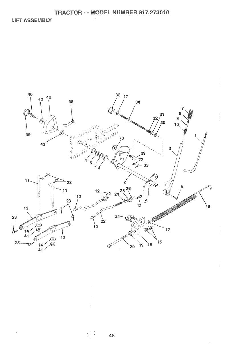
LmF_ASSEMBLY
40
'TRACTOR ° o MODEL NUMBER 917.273010
39
42
23
13
23
22
12
12
20 !9 18
15
1
\
48
Page 49
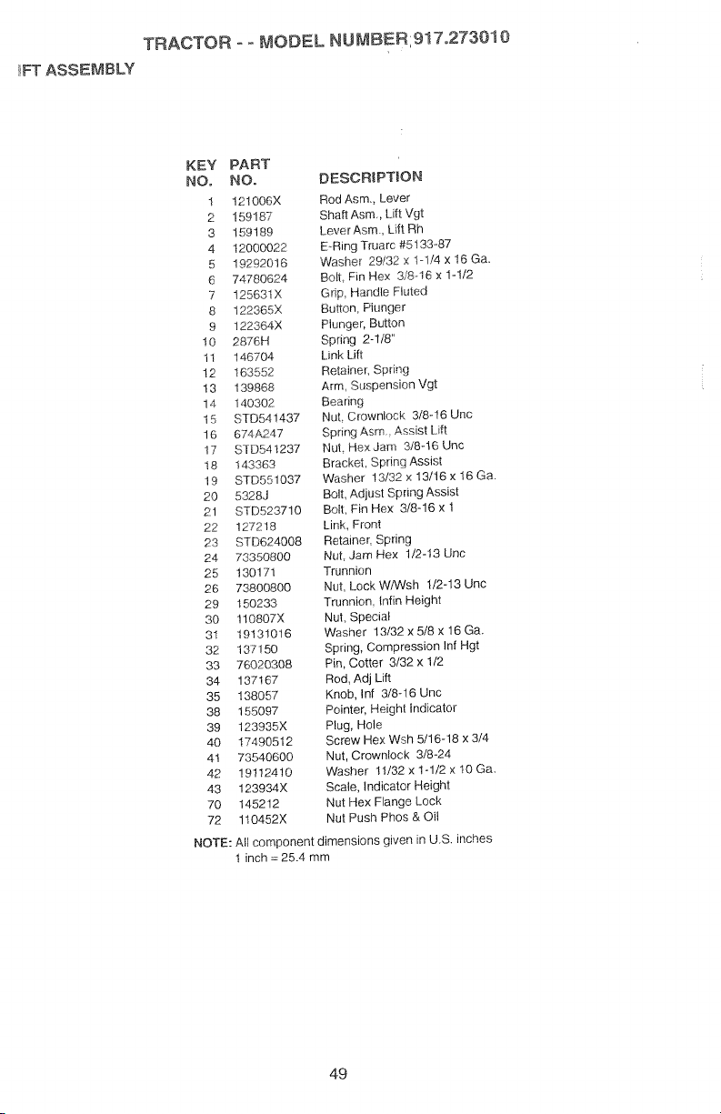
FT ASSEMBLY
TRACTOR o- MODEL NU_B'ERI917,273010
KEY PART
NOo NO. DESCR)PTION
1 12!006× Rod Asm. Lever
2 159187 Shaft Asm., Lift Vgt
3 159189 LeverAsm, Lift Rh
4 12000022 E.-RIng Truarc #5133-87
5 19292016 Washer 29/32 x 1-1/4 x 18 Ga.
6 74780624 Boll Fin Hex 3/8-16 x 1-1/2
7 125631X Gdp, Handle Fluted
8 122365X Button, Plunger
9 122364X Plunger, Button
!0 2876H Spring 2-1/8"
11 146704 Link Lift
12 163552 Retainer, Spring
13 139868 Arm Suspension Vgt
14 140302 Bearing
15 STD541437 Nut Crownlock 3/8-16 Unc
16 674A247 Spring Asm. Assist Lift
17 STD541237 Nut Hex Jam 3/8-16 Unc
18 143363 Bracket, Spring Assist
19 STD551037 Washer 13/32 x 13/16 x !6 Ga.
20 5328J Bolt, Adjust Spring Assist
21 STD523710 Belt, Fin Hex 3/8-16 x 1
22 127218 Link, Fmnf
23 STD624008 Retainer, Spring
24 73350800 Nut, Jam Hex 1/2-13 Unc
25 130171 Trunnion
26 73800800 Nut Lock W/Wsh 1/2-13 Unc
29 150233 Trunnion Infin Height
30 110807X Nut, Special
31 19131016 Washer 13/32xS/8×16Ga.
32 137150 Spring, Compression Inf Hgt
33 76020308 Pin, Cotter 3/32 x 1/2
34 137167 Rod, Adj Lift
35 138057 Knob, Inf 3/8-16 Uric
38 155097 Pointer, Height indicator
39 123935X Plug, Hole
40 17490512 Screw Hex Wsh 5/16-18 x 3/4
41 73540600 Nut, Crownlock 3/8-24
42 19112410 Washer 11/32 x 1-1/2 x 10 Ga.
43 123934X Scale, Indicator Height
70 145212 Nut Hex Flange Lock
72 110452X Nut Push Phos & Oil
NOTE: All component dimensions given in U.S. inches
1 inch = 25.4 mm
49
Page 50
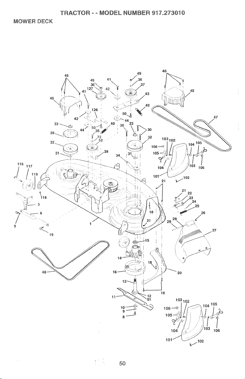
MOWERDECK
TRACTOR°°MOOF=LHUMBER9i7.2730i0
45
\
42
45
/
47
" "":'I' ; 118
5
104
10
6
t9
_..102
21
106
21
22
2.6
', 50
Page 51

TRACTOR - ° MODEL NUr,_BER;917o273010
,_OWERDECK
KEY PART KEY PART
NO, NO. DESCRIPTION NO. NO,
1 156948 Deck Weldment 34 144945
3 138457 Bracket Asm., Sway Bar 35 17490628
5 STD624008 Retainer Spring
6 130832 Arm, Suspension, Rear 38 STD551037
8 850857 Bolt Patched 3/8-24 x 1- 38 1E_08.6
9 STD551137 Washer_ Lock Hvy, 40 137273
10 140296 Washer_ Ha_ B!ade, Mower 41 17490620
tl 152443 Blade, 46" Mower Deck 42 122052X
12 129895 Bearing_ Ball, Mandrel 44 133943
13 137553 Shaft Asm. w,__ower 46 137729
14 137152 Housing, Mandrel 49 STD541437
15 110485X Bearing, Ball, Mandrel 50 72110612
16 140329 Stripper, Mower Round
18 STD533106 Bolt, Carnage 5116-18 x 5/8 51 153390
19 132827 Bolt, Hex Head, Shoulder 52 156493
20 145055 Baffle, Vorte× Mower 46" 101 145579
21 STD541431 Nut, Crowntock 5/16-18 102 71161010
22 134753 Stiffener, Bracket
23 131267 Bracket, Deflector 105 160793
24 105304X Cap, Sleeve 106 2029J
25 149287 Spring, Torsion, Deflector 116 137644
26 110452X Nut, Push 117 133957
27 157788 Shield, Deflector Mower 118 73930600
28 19111018 Washer t1132 x 5/8 x 16
29 131491 Rod Hinge 126 144948
80 157722 Screw, Thd Ro!ling Washer
31 129963 Washer, Spacer Mower
32 153531 Pulley, Mandrel
33 137266 Nut, Rg. Top Lock Cntr.
(Sway Be0 37 131494
1/4 Gr. 8 39 144917
Unplated 3/6
Vented
Mulching 43 144949
#6204 45 145059
Bearing (_ncludes Key No. 47 144959
12) 48 139573
5/16-t8 72 19131616
UNC
Ga. 119 19121414
Head - - i 57251
Vented
9/16
103 STD551110
104 19061216
127 146763
- - 143651
NOTE: All component dimensions given in U.S. inches
1 inch = 25.4 mm
DESCRJPTJON
Anchor, Spring Deck 46"
Screw_ Thdroil 3/8-16 x 1-3/4
rytt
Washer 13/32 × 13/16 × 16 Ga.
Pulley, Idler, Flat
Keeper, Belt, idler
Pulley, _dler, Ddven
Spdng, Secondary 44/46/50
Vent
Screw; Thdroll 3/8-16 × 1-1/4
Spacer, Reiainer
Arm Idler Secondary
Washer, Hardened
Covet Mandret Deck
Screw, ThdrolL 1/4-20 x 5/8
V-Belt, Mower, Secondary
V-Belt, Mower, Primary
Nut, Crownloek 3/8-16 UNC
Bolt Carriage 3/8-16 x 1-1/2 Gr.
5
Washer Felt
Pulley idler 46" Pdm. Drive
Washer 13/32 x 1 x 18Ga.
Cover, Mulching
Screw
Washer, Lock #10
Washer
Latch Asm. Bagger
Nut, Weld
Bolt, Shoulder
Gauge Wheel
Nut, Centerlock 3/8-16 UNC
Washer 3/8 x 7/8 x 14 Ga.
Arm, Idler. Primary Deck 46"
Pulley, Idler, V-Groove Dim. 4.25
Mower Service 46" (Standard
Deck - Order separately
mulching components Key Nos.
101-106)
Mandrel Asm 44/50 Service
(Includes Key Nos. 8-10, 12-15,
3i and 33)
51
Page 52
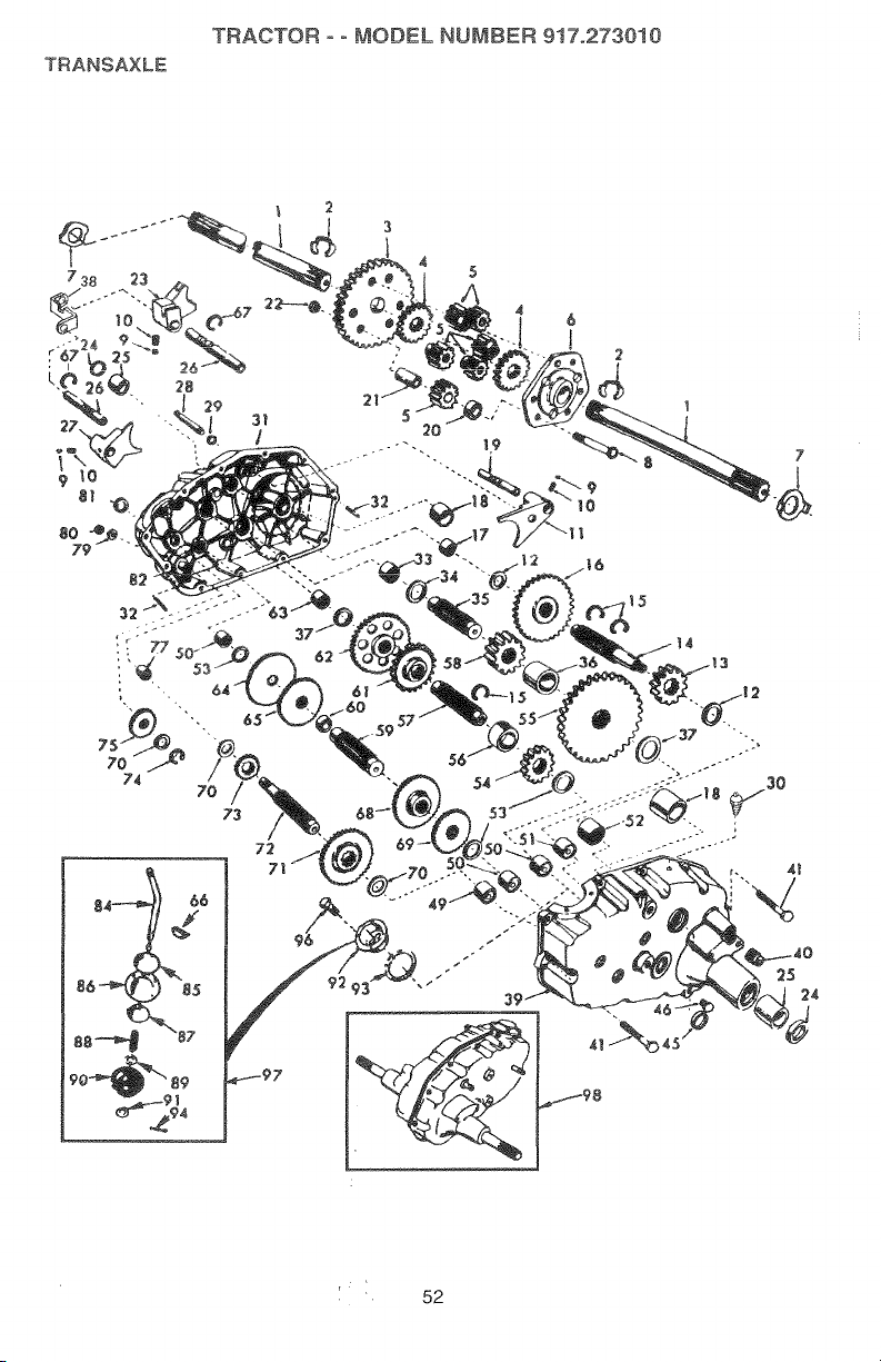
TRANSAXLE
TRACTOR - ° MODEL NUMBER 917.273010
' 52
25
:24
Page 53
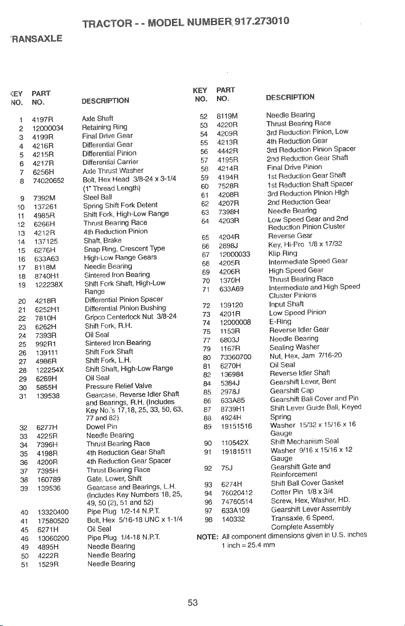
_RANSAXLE
<EY
PART
NOo
NO.
1
4197R
2
12000034
3
4199R
4
4216R
5
4215R
6
4217R
7
6256H
8
74020652
9
7392M
10
137261
11
4985R
12
6266H
13
4212R
14
137125
15
6276H
16
633A63
17
8118M
18
8740H1
19
122238X
20
4218R
21
6252H1
22
7810H
23
6262H
24
7393R
25
992R1
26
139111
27
4986R
28
122254X
29
6269H
30
5855H
31
139538
32
6277H
33
4225R
34
7396H
35
4198R
38
4200R
37
7395H
38
160789
39
139536
40
1332O4OO
41
17580520
45
6271R
48
13060200
49
4895H
50
4222R
51
1529R
TRACTOR oo MODEL NUMBEN, _1 lo,_1301v
DESCR_PTtON NO. NO, DESCRfPTION
Axle Shaft 52 81!9M Needle Beanng
Retaining Ring 53 4220R Thrust Beadng Race
Final Ddve Gear 54 4209R 3rd Reduction Pinion, Low
Differential Gear 55 4213R 4th Reduction Gear
Differential Pinion 56 4442R 3rd Reduction Pinion Spacer
Differential Carder 57 4195R 2nd Reduction Gear Shaft
A×le Thrust Washer 58 4214R Final Drive Pinion
Bolt, Hex Heed 3/8-24 x 3-1/4 59 4194R 1st Reduction Gear Shaft
(1" Thread Length) 60 7528R 1st Reduction Shaft Spacer
Steel Ball 61 4208R 3rd Reduction Pinion High
Spring Shift Fork Detent 62 4207R 2nd Reduction Gear
Shift Fork, High-Low Range 63 7398H Needle Bearing
Thrust Beating Race 64 4203R Low Speed Gear and 2nd
4th Reduction Pinion Reduet!on Pinion Cluster
Shaff, Brake 65 4204R Reverse Gear
Snap Ring Crescent Type 66 289&J Key, Hi-Pro 1/8 x 17/32
High-Low Range Gears 67 12000033 Klip Ring
Needle Bearing 68 4205R Intermediate Speed Gear
Sintered Iron Bearing 69 4206R High Speed Gear
Shift Fork Shaft, High-Low 70 1370H Thrust Bearing Race
Range 71 633A69 Intermediate end High Speed
Differential Pinion Spacer Cluster Pinions
Differential Pinion Bushing 72 189120 Input Shaft
Gripco Centedock Nut 3/8-24 73 4201R Low Speed Pinion
Shift Fork, R.H. 74 12000008 E-Ring
Oil Seal 75 1153R Reverse Idler Gear
Sintered Iron Bearing 77 6803J Needle Bearing
Shift Fork Shaft 79 1167R Sealing Washer
Shift Fork, LH. 80 73360700 Nut, Hex, Jam 7/16-20
Shift Shaft, High-Low Range 81 6270H Oil Seal
Oil Seal 82 136984 Reverse Idler Shaft
Pressure Relief Valve 84 5384J Gearshift Lever, Bent
Gearcase, Reverse Idler Shaft 85 2978J Gearshift Cap
and Bearings, R.R. (Includes 86 633A85 Gearshift Bail Cover and Pin
Key No._s 17,t8, 25, 33, 50, 63, 87 8739H1 Shift Lever Guide Bali, Keyed
77 and 82) 88 4924H Spring
Dowel Pin 89 19151516 Washer 15/32 × 15/16 x 16
Needle Bearing Gauge
Thrust Bearing Race 90 110542X Shift Mechanism Seal
4th Reduction Gear Shaft 91 19181511 Washer 9/16 x 15/16 x 12
4th Reduction Gear Spacer Gauge
Thrust Bearing Race 92 75J Gearshift Gate and
Gate, Lower, Shift Reinforcement
Gearr_se and Bearings, LH. 93 6274H Shift Ball Cover Gasket
(Includes Key Numbers 18, 25, 94 76020412 Cotter Pin 1/8 x 3/4
49, 50 (2), 51 and 52) 96 74760514 Screw, Hex, Washer, HD.
Pipe Plug 1/2-14 N.P.T. 97 633A109 Gearshift LeverAssemb_y
Bolt, Hex 5/16-18 UNC x 1-1/4 98 140332 Transaxle, 6 Speed,
Oil Seal Complete Assembly
Pipe Plug 1/4-18 N.R£ NOTE: All component dimensions given in U.S. inches
Needle Bearing 1 inch = 25.4 mm
Needle Bearing
Needle Bearing
KEY PART
53
Page 54
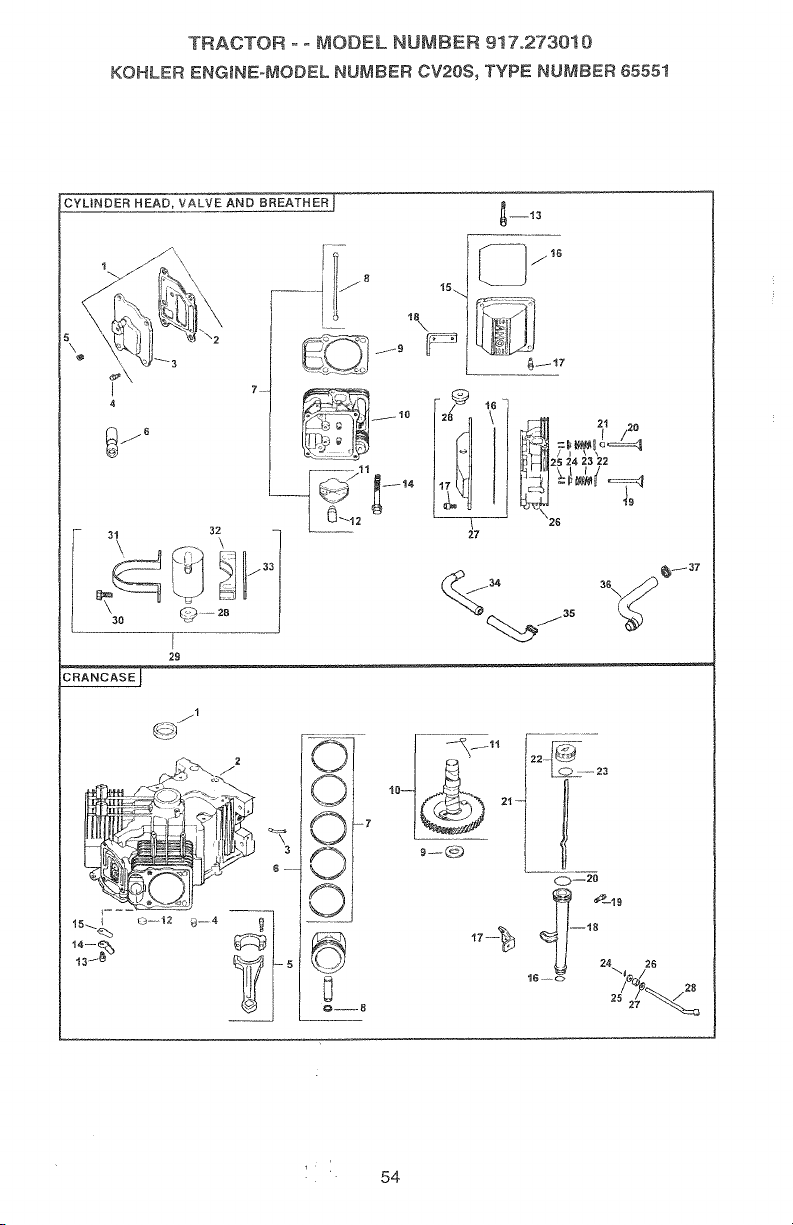
TRACTORooMODELNUMBER917.273010
KOHLER ENG_NEoMODEL NUMBER CV20$_ TYPE NUMBER 65551
4
I _::m 21 20
j6
25 24 23 22
30 _
27
_3 t28
29
Ij3
7
f 1tI
\26
L0--23
' 54
Page 55

TRACTOR o- MODEL NUMBEH,91/°,_/3_v
KOHLER ENGJNEoMODEL NUMBER CV20S, TYPE NUMBER 65551
HEADNALVE/BREATHER
KEY PART
NO. NO. DESCRIPTION
1 24-033-03
Kit, breather cover w/gasket ! 24-032-01
(includes 2,3) 2
2 24-041-23
3 24-096-15
4 M-0645020
GaskeL breather
Cover, breather 3 24294q3
Screw, hex. flange M6xl.0x20 4 !2-380-17
(4} 5 24-O67-13
5
10
11
12
13
14
15
16
17
18
19
20
21
22
23
24
25
26
27
6
7
6
9
X-75-23
!2-.35!-02
24W55-66
24-4 t t-05
24_04t-08
24_3!8-12
25_ 186-01
24-599-0t
M-0640034
12-086-16
24-755-74
24-.153-16
24-086-32
24-445-01
24-016-01
24_016-02
24-017-01
24-017-02
24-032-05
235011
24-089-02
!2-!73-0!
12-755-03
24-318-11
24-755-76
Plug, allen hd. 1/8" 24-067q4
Lifter, vatve (4) 6 24-874-01
Kit, valve train (includes 8,11,12)
Rod, push (4) 24-874-02
Gasket, cylinder head (2) 24-874-03
Nead assembly, #2 cylinder 7. 24-108-0!
Arm, rocker (4) 24-108-02
Pivot, rocker arm (4) 24-108_03
Screw_ hex. flange M6x1.0x34 8 24-0!8-0!
(4) 9 !2-422-09
Screw, hex. flange M10x1.5x90 12-422-13
(8) ! 2-422-07
Kit valve cover -.plain 12-422-08
(Includes 16,17) 12-422-10
O-Ring 12-422oll
Screw, shoulder (4) 12-422-12
Strap lifting 10 24-010-03
Valve, exhaust (Std.) (2) 11 24-089-21
Valve. exhaust (.25) (2) 12 52-139-09
Vafve, intake (Std.) (2) 13 M-0545010
Vaive_ intake (.25) (2}
Seal. valve stem (2) 14 24-018-04
Retainer, spring (4) 15 24-402-05
Spring valve (4) 16 12-153-01
Cap, valve spring (4) 17 24-126-19
Kit, retainer (4) 18 12-123-04
Head assembfy, #1 cylinder 19 M-0545016
Kit, valve cover - breather 20 12-153-02
(Incl. 16,17,28) 21 24-038_04
28
29
3O
25-313-02
24_755-57
M-0545016
Grommet, rubber
Kit, breather separator 22 24-755-46
(Includes 28,30-33) 23 12-153-03
Screw, hex. flange M5x0.Sx16 24 12-380-04
(2) 25 M-0631005
31
32
33
34
35
36
37
24-445-02
24-126-44
24-112-!2
24-294-06
24-326-13
24-326-14
X-426-9
Strap, breather 26 12-032-01
Bracket, breather separator 27 X-25-!02
Spacer 28 24-144-01
Fitting
Hose, breather
Hose, breather
Clamp, hose (2)
CRANKCASE
KEY PART
NO. NO.
DESCRIPTION
Seal, oil front
Crankcase
(USE: Miniblock 24 782 05)
Fitting
Pin dowel locating (6)
CoRRecting Rod (Std.) (2)
Connecting Rod (.25) (2)
Piston wiring Set (Std.) (2)
(Includes 7,8)
Piston wiring Set (.25) (2)
Piston w/Ring Set (.50) (2)
Ring Set (Std) (2)
Ring Set (.25) (2)
Ring Set (.50) (2)
Retainer, piston pin (4)
Shim, camshaft (A.R.)
Shim, camshaft (A.R.)
Shim, camshaft (A.R.)
Shim, camshaft (A.R.)
Shim, camshaft
Shim, camshaft (A.R.)
Shim, camshaft (A.R.)
Camshaft (Includes 11)
Spring, actuating (ACR)
Plug_ cup
Screw, hex. flange M5x0.Sxl0
(2)
Retainer, reed (2)
Reed, breather (2)
O-Ring, lower el! fill tube
Bracket, oil fill tube
Tube, oil fill
Screw, hex. flange M5x0.8x16
O-Ring, upper oil fill tube
Dipstick assembly (Includes
22,23)
Kit, oil fil! cap (Includes 23)
O-Ring, dipstick
Pin, hitch
Washer, plain 6 mm
Seal, governor cross shaft
Washer. plain !/4"
Shaft, governer cross
55
Page 56

TRACTOR oo MODEL NUMBER 917.2730!0
KOHLER ENG_NE=tVIODELNUMBER CV20S, TYPE NUMBER 65551
CRANKSHAFT T
FUEL SYSTEM l
/
f
EXHAUST I
0
--1
12
5
/ 9
7 8
14
Page 57

TRACTOR oo MODEL NUMB=R, 917°_1_000
KOHLER ENGINEoMODEL NUMBER CV20S, TYPE NUMBER 65551
CRANKSHAFT
KEY PART
NO. NO.
1 24-014-72
2 52-139-09
EXHAUST
KEY PART
NO, NO.
1 24-041-02
2 25-072-04
24-522-16
24-782-05
24-755-03
DESCRIPTRON
Crankshaft (includes 2)
Plug, cup
DESCRIPTION
Gasket, exhaust (2)
Stud, M8x! .25x33 (4}
Short Block
Minibiock
Gasket Set
FUEL SYSTEM
KEY PART
NO, NO.
1 24-853_25
2 24-041=!5
3
4 24-041-14
5 M-0629095
6 M-0641060
7 47-!54-01
8 24,353-03
9 X-426-9
10 24086-12
11 24-393-04
12 24-100-01
t3 25-353-03
14 24-050-02
NOT _LLUSTRATED
24-757-18
24-757-19
24-757-20
24-757-22
DESCRI_'ION
Kit, carburetor w/gaskets
(Includes 2-4)
Gasket, carburetor
Carburetor assembly
(For information oniy not
available separately)
(_nc!udes 24 757 !8, 24-053-25,
24-757-19, 24-757-20,
24-757-22)
Gasket, air cleaner base
Stud, M6xl.0x95 (2)
Nut, hex. flange M6x1.0 (2)
Clip, cabJe
Line, fuel 10-5/8" (2)
Clamp, hose (6)
Screw, hex. cap. M6x1.7x18 (2)
Pump, rue! -pulse
Nut, plastic (2)
Line, fuel 13-1/2"
Filter, fuel
Kit, overhaul w/gaskets
Kit, choke repair w/gaskets
Kit, gasket
Kit, solenoid replacement w/gas-
kets
Page 58

SUGGESTED GUIDE FOR SIGH'RNG SLOPES FOR SAFE OPERATION
ONLY RIDE UP AND DOWN HILL,
NOT ACROSS H_LL
SIGHT AND HOLD THiS LEVEL WiTH
SKY LINE OR TREE.
15° MAX.
Operate your Tractor up and down the face of s_opes (not
greater than 15°), never across the face. Make turns gradu-
ally to prevent tipping or _oss of control Exercise extreme
caution when changing direction on slopes,
1
Page 59

For the repair or replacement parts you need
delivered directly to your home
Call 7 am o7 pm, 7 days a week
1-800°366oPART
(1_800-388W278)
Para ordenar piezas con entrega a
domicilio - !=800-859-7084
For in-house major brand repair service
Call 24 hours a day, 7 days a week
1-800o4oREPAIR
(1-800-473-7274)
Para pedir servicio de reparaci6n a
domicJJio- 1o800o878o5811
For the location of a Sears Parts and
Repair Center in your area
Call 24 hours a day, 7 days a week
1-800-488 i 222
For information on purchasing a Sears
Maintenance Agreement or to inquire
about an existing Agreement
Call 9 am - 5 pro, Monday-Saturday
1°800°827-6655
When requesting service or ordering
parts, always provide the following
information:
®Product Type * Part Number
Model Number , Part Description
Amenca_s Repair Spectal_sts
163940 Rev, 2 4.7.98 JH Printed in U,SoA.
 Loading...