

Page 1

Owner’s Manual
20 HP
ELECTRIC START
48" MOWER
6 SPEED TRANSAXLE
LAWN TRACTOR
Model No.
917.272233
• Safety
• Assembly
• Operation
• Maintenance
• Repair Parts
CAUTION:
Read and foliow all
Safety Rules and Instructions
before operating this equip
ment.
Sears, Roebuck and Co., Hoffman Estates, IL 60179
Visit our Craftsman website: www.sears.com/craftsman
For answers to your questions
about this product, Call:
1-800-659-5917
Sears Craftsman Help Line
5 am ■ 5 pm, Mon - Sal
Page 2

TABLE OF CONTENTS
..2 Maintenance
Service and Adjustments...
..3
Storage....................................
..6
Troubleshooting
..8
12 Repair Parts
Parts Ordering
18
................
.........
................
............
..............
..............
..............
..............
.. Back Cover
18
22
29
30
34
WARRANTY
LIMITED TWO YEAR WARRANTY ON CRAFTSMAN RIDING EQUIPMENT PARTS
For two (2) years from the date of purchase, if this Craftsman Riding Equipment is
maintained, lubricated and tuned up according to the instructions in the owner’s
manuai, Sears wiil repair or repiace, free of charge, any parts found to be defective in
material or workmanship. Warranty service is avatiabie free of charge by reluming your
Craftsman riding equipment to your nearest Sears Service Center, in-home warranty
service is available but a trip charge will apply. This warranty applies only while this
product is in the United States.
This Warranty does not coven
■ Expendable items which become worn during normal use, such as blades, spark
plugs, air cleaners, belts and oil filters.
• Tire replacement or repair caused by punctures from outside objects, such as nails,
thorns, stumps, or glass.
• Repairs necessary because of operator abuse, including but not limited to, damage
caused by towing objects beyond the capability of the riding equipment, impacting
objects that bend the frame or crankshaft, or over speeding the engine.
• Repairs necessary because of operator negligence, including but not limited to,
electrical and mechanical damage caused by improper storage, failure to use the
proper grade and amount of engine oil, failure to keep the deck clear of flammable
debris, or the failure to maintain the equipment according to the instructions con
tained in the owner^s manual.
• Engine (fuel system) cleaning or repairs caused by fuel determined to be contami
nated or oxidized (stale), in general, fuel should be used within thirty (30) days of its
purchase date.
• Riding equipment used for commercial or rental purposes. A product is “used for
commercial purpose" if is used for any purpose other than single family household
dwellings or in usage where profit is made.
LIMITED 90 DAY WARRANTY ON BATTERY
For ninety (90) days from date of purchase, if any battery included with this riding
equipment proves defective in material or workmanship and our testing determines the
battery will not hold a charge. Sears will replace the battery at no charge. Warranty
senrice is available free of charge by returning your Craftsman riding equipment to
your nearest Sears Service Center. In-home warranty service is available but a trip
charge will apply. This warranty applies only while this product is in the United States.
TO LOCATE THE NEAREST SEARS SERVICE CENTER OR TO SCHEDULE IN-HOME
WARRANTY SERVICE, SIMPLY CONTACT SEARS AT 1-800-4-MY-HOME
This Warranty gives you specific legal rights, and you may also have other rights which
may vary from state to state.
Sears. Roebuck and Co., D/817 WA, Hoffman Estates, IL 60179
Page 3

SAFETY RULES
IMPORTANT: This cutting machine is capable of amputating hands and feet and
throwing objects. Failure to observe the following safety instructions could result in
serious injury or death.
GENERAL OPERATION
I,
Read, understand, and follow all
instructions in the manual and on the
machine before starting.
Only allow responsible adults, who are
familiar with the instructions, to operate
the machine.
Clear the area of objects such as
rocks, toys, wire, etc., which could be
picked up and thrown by the blade.
Be sure the area is clear of other
people before mowing. Stop machine
if anyone enters the area.
Never carry passengers.
Do not mow in reverse unless abso*
lutely necessaiy. Always look down
and behind before and while backing.
Be aware of the mower discharge
direction and do not point it at anyone.
Do not operate the mower without
either the entire grass catcher or the
guard In place.
Slow down before turning.
Never leave a running machine
unattended. Always turn off blades, set
parking brake, stop engine, and
remove keys before dismounting.
Turn off blades when not mowing.
Stop engine before removing grass
catcher or unclogging chute.
Mow only in daylight or good artificial
light.
Do not operate the machine while
under the influence of alcohol or drugs.
Watch for traffic when operating near or
crossing roadways.
Use extra care when loading or
unloading the machine into a trailer or
truck.
Data indicates that operators, age 60
years and above, are involved in a
large percentage of riding mowerrelated injuries. These operators
should evaluate their ability to operate
the riding mower safely enough to
protect themselves and others from
serious injury.
Keep machine free of grass , leaves or
other debris build-up which can touch
hot exhaust / engine parts and burn .
Do not allow the mower deck to plow
leaves or other debris which can cause
build-up to occur. Clean any oil or fuel
spillage before operating or storing the
machine . Allow machine to cool refore
storage.
II. SLOPE OPERATION
Slopes are a major factor related to loss-of-
control and tipover accidents, which can
result in severe injury or death. All slopes
require extra caution. If you cannot back up
the slope or if you feel uneasy on it, do not
mow it.
DO:
• Mow up and down slopes, not across.
• Remove obstacles such as rocks, tree
limbs, etc.
• Watch for holes, ruts, or bumps.
Uneven terrain could overturn the
machine. Tall grass can hide ob
stacles.
• Use slow speed. Choose a low gear
so that you will not have to stop or shift
while on the slope.
• Follow the manufacturer’s recommen
dations for wheel weights or counter
weights to improve stability.
• Use extra care with grass catchers or
other attachments. These can change
the stability of the machine.
• Keep all movement on the slopes slow
and gradual. Do not make sudden
changes in speed or direction.
• Avoid starting or stopping on a slope. If
tires lose traction, disengage the
blades and proceed slowly straight
down the slope.
DO NOT:
• Do not turn on slopes unless neces
sary, and then, turn slowly and gradu
ally downhill, if possible.
• Do not mow near drop-offs, ditches, or
embankments. The mower could
suddenly turn over if a wheel is over
the edge of a cliff or ditch, or if an edge
caves in.
• Do not mow on wet grass. Reduced
traction could cause sliding.
• Do not try to stabilize the machine by
putting your foot on the ground.
• Do nof use grass catcher on steep
slopes.
Page 4

SAFETY RULES
III. CHILDREN
Tragic accidents can occur if the operator
is not alert to the presence of children.
Children are often attracted to the
machine and the mowing activity. Never
assume that children will remain where
you last saw them.
• Keep children out of the mowing area
and under the watchful care of another
responsible adult.
• Be alert and turn machine off if children
enter the area.
• Before and when backing, look behind
and down for small children.
• Never carry children. They may fall off
and be seriously injured or interfere
with safe machine operation.
■ Never allow children to operate the
machine.
• Use extra care when approaching blind
corners, shrubs, trees, or other objects
that may obscure vision.
IV. SERVICE
• Use extra care in handling gasoline
and other fuels. They are flammable
and vapors are explosive.
-Use only an approved container.
- Never remove gas cap or add fuel
with the engine running. Allow
engine to cool before refueling. Do
not smoke.
- Never refuel the machine indoors.
- Never store the machine or fuel
container inside where there is an
open flame, such as a water heater.
• Never run a machine inside a closed
area.
• Keep nuts and bolts, especially blade
attachment bolts, tight and keep
equipment in good condition.
• Never tamper with safety devices.
Check their proper operation regularly.
• Keep machine free of grass, leaves, or
other debris build-up. Clean oil or fuel
spillage. Allow machine to cool before
storing.
• Stop and inspect the equipment if you
strike an object. Repair, if necessary,
before restarting.
• Never make adjustments or repairs
with the engine running.
• Grass catcher components are subject
to wear, damage, and deterioration,
which could expose moving parts or
allow objects to be thrown. Frequently
check components and replace with
manufacturer's recommended parts,
when necessary.
• Mower blades are sharp and can cut.
Wrap the blade(s) or wear gloves, and
use extra caution when senricing them.
• Check brake operation frequently.
Adjust and service as required.
Be sure the area is clear of other
people before mowing. Stop machine if
anyone enters the area.
Never carry passengers or children
even with the blades off.
Do not mow in reverse unless abso
lutely necessary. Always look down
and behind before and while backing.
Never carry children. They may fall off
and be seriously Injured or interfere
with safe machine operation.
Keep children out of the mowing area
and under the watchful care of another
respronsibie adult.
Be alert and turn machine off if children
enter the area.
Before and when backing, look behind
and down for small children.
Mow up and down slopes (15° Max),
not across.
Remove obstacles such as rocks, tree
limbs, etc.
Watch for holes, ruts, or bumps.
Uneven terrain could overturn the
machine. Tall grass can hide obstacles.
Page 5

SAFETY RULES
• Use slow speed. Choose a low gear so
that you will not have to stop or shift
while on the slope.
• Avoid starting or stopping on a slope. If
tires lose traction, disengage the
blades and proceed slowly straight
down the slope.
• If machine stops while going uphill,
disengage blades, shift into reverse
and back down slowly.
• Do not turn on slopes unless neces
sary, and then, turn slowly and gradu
ally downhill, If possible.
ALook for this symbol to point out
important safety precautions. It means
CAUTIONllI BECOME ALERT!!! YOUR
SAFETY IS INVOLVED.
ACAUTION: In order to prevent acciden
tal starting when setting up, transporting,
adjusting or making repairs, always
disconnect spark plug wire and place
wire where it cannot contact spark plug.
i&CAUTION: Do not coast down a hill in
neutral, you may lose control of the
tractor.
^CAUTION; Tow only the attachments
that are recommended by and comply
with specifications of the manufacturer of
your tractor. Use common sense when
towing. Operate only at the lowest
possible speed when on a slope. Too
heavy of a load, while on a slope, Is
dangerous. Tires can lose traction with
the ground and cause you to lose control
of your tractor.
^WARNING: Engine exhaust, some of its
constituents, and certain vehicle compo
nents contain or emit chemicals known to
the State of California to cause cancer
and birth defects or other reproductive
harm.
^WARNING: Battery posts, terminals and
related accessories contain lead and lead
compounds, chemicals known to the State
of California to cause cancer and birth
defects or other reproductive harm. Wash
hands after handling.
Page 6

PRODUCT SPECIFICATIONS
GASOLINE
CAPACITY
AND TYPE;
OILTYPE
(API-SF-SJ):
OIL CAPACITY:
SPARK PLUG:
(GAP: .030“)
GROUND SPEED 1st
TIRE PRESSURE:FRONT:14PSI
CHARGING
SYSTEM; 15 AMPS @3600 RPM
BATTERY: AMP/HR: 30
BLADE BOLT
TORQUE:
CONGRATULATIONS on your purchase
of a new tractor. It has been designed,
engineered and manufactured to give
you the best possible dependability and
performance.
Should you experience any problem you
cannot easily remedy, please contact
your nearest Sears or other qualified
service center. We have competent, well-
trained technicians and the proper tools
to service or repair this tractor.
Please read and retain this manual. The
instructions will enable you to assemble
and maintain your tractor properly.
Always observe the “SAFETY RULES’.
3.5 GALLONS
UNLEADED
REGULAR
SAE10W30 (above 32"F)
SAE 5W-30 (below 32°F)
W/FILTER: 4.5 PINTS
W/OFILTER: 4.0 PINTS
CHAMPION RC12YC
1.2
(MPH): 2nd
3rd
4th 3.5
5th
6th 5.3
REVERSE: 1.5
REAR: 10PSI
MIN. CCA; 240
CASESIZE:U1R
45-^5 FT. LBS.
1.5
2.4
4.8
REPAIR AGREEMENT
A Repair Agreement is available on this
product. Contact your nearest Sears
store for details.
CUSTOMER RESPONSIBILITIES
• Read and observe the safety rules.
• Follow a regular schedule in maintain
ing, caring for and using your tractor.
• Follow the instructions under “Mainte
nance” and "Storage" sections of this
owner’s manual.
^WARNING: This tractor is equipped
with an internal combustion engine and
should not be used on or near any
unimproved forest-covered, brushcovered or grass-covered land unless the
engine’s exhaust system is equipped with
a spark arrester meeting a|;^licable local
or state laws (if any). If a spark arrester is
used, it should be maintained in effective
working order by the operator.
In the state of California the above is
required by law (Section 4442 of the
California Public Resources Code).
Other states may have similar laws.
Federal laws apply on federal lands. A
spark arrester for the muffler is available
through your nearest Sears service
center. (See REPAIR PARTS section of
this manual).
Page 7
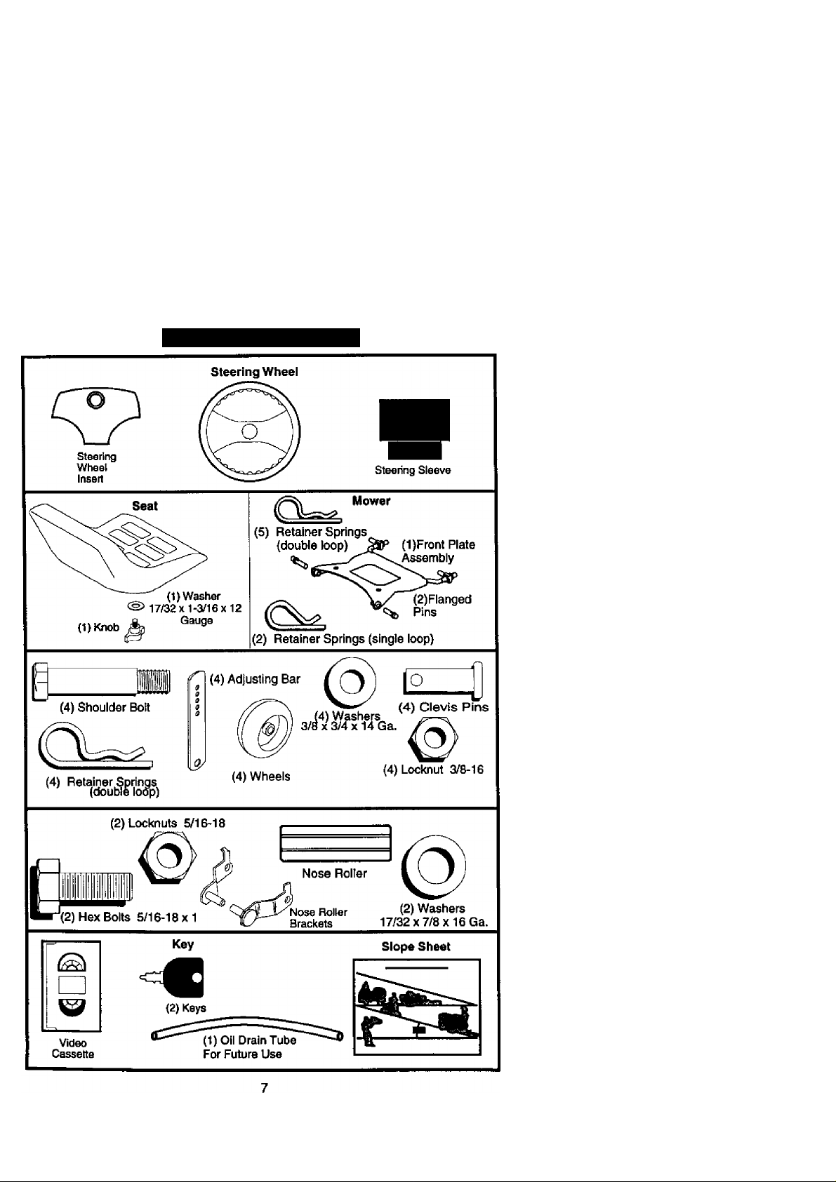
UNASSEMBLED PARTS
Page 8
ASSEMBLY
Your new tractor has been assembled at the factory with exception of those parts left
unassembled for shipping purposes. To ensure safe and proper operation of your
tractor ali parts and hardware you assemble must be tightened securely. Use the
correct tools as necessary to insure proper tightness. Review the video cassette before
you begin.
TOOLS REQUIRED FOR ASSEMBLY
A socket wrench set will make assembly
easier. Standard wrench sizes you need
are listed below.
(1) 9/16” Wrench (1) 3/4“ Socket w/
(1) 1/2" wrench drive ratchet
(1) Utility knife (1) Pliers
(1) Tire pressure gauge
When right or left hand is mentioned in
this manual, it means, from your point of
view, when you are in the operating
position (seated behind the steering
wheel).
TO REMOVETRACTOR FROM
CARTON
UNPACK CARTON
1. Remove all accessible loose parts
and parts boxes from shipping carton.
2. Cut, from top to bottom, along lines on
all four corners of shipping carton, and
lay panels flat.
3. Remove mower and package materi
als.
4. Check for any additional loose parts
or boxes and remove.
BEFORE REMOVINGTRACTOR
FROM SKID
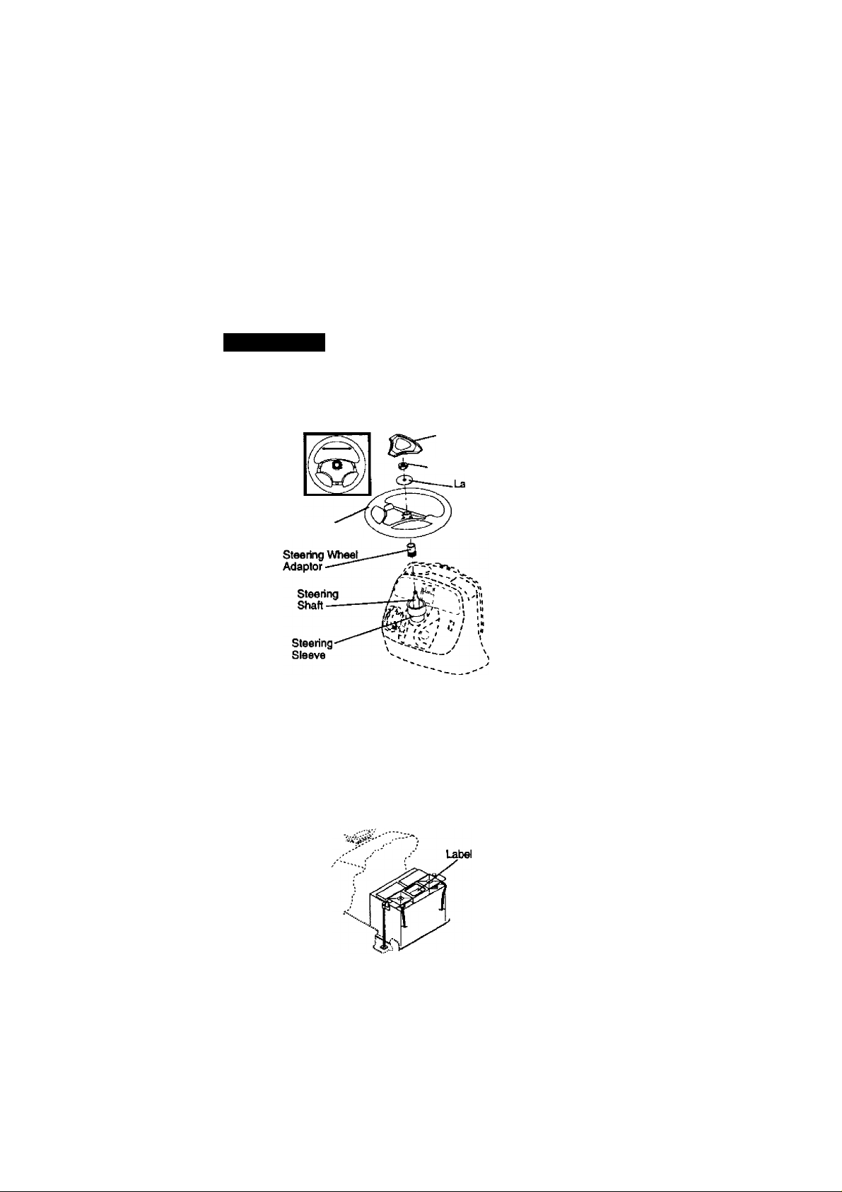
ATTACH STEERING WHEEL
1. Remove lock nut and large flat washer
from steering shaft.
2. Position front wheels of the tractor so
they are pointing straight forward.
3. Slide the steering sleeve over the
steering shaft.
4. Position steering wheel so cross bars
are horizontal (left to right) and slide
onto steering wheel adapter.
5. Secure steering wheel to steering
shaft with lock nut and large flat
washer previously removed. Tighten
securely.
6. Snap steering wheel insert into center
of steering wheel.
7. Remove protective materials from
tractor hood and grill.
IMPORTANT: Check for and remove any
staples in skid that may puncture tires
where tractor is to roll off skid.
Steering Wheel
HOWTO SET UPYOURTRACTOR
CHECK BATTERY
1. Lift hood to raised position.
NOTE: If this battery is put into service
after month and year indicated on label
Oabel located between terminals) charge
battery for minimum of one hour at 6-10
amps. (See "BATTERY” in MAINTE
NANCE section of this manual for
charging instructions).
INSTALLSEAT
Adjust seat before tightening adjustment
knob.
1. Remove adjustment knob and flat
washer securing seat to cardboard
packing and set aside for assembly of
seat to tractor.
Pivot seat upward and remove from
2.
the cardboard packing. Remove the
cardboard packing and discard.
Steering Wheel
Insert
Lock Nut
Tge Rat
Washer
Page 9

3. Place seat on seat pan so head of
shoulder bolt is positioned over large
slotted hole in pan.
4. Push down on seat to engage
shoulder bolt in slot and pull seat
towards rear of tractor.
5. Pivot seat and pan forward and
assemble adjustment knob and flat
washer loosely. Do not tighten.
6. Lower seat into operating position and
sit in seat.
7. Slide seat until a comfortabie position
is reached which allows you to press
clutch/brake pedal all the way down.
8. Get off seat without moving its
adjusted position.
9. Raise seat and tighten adjustment
knob securely.
NOTE: You may now roll or drive your
tractor off the skid. Foliow the appropriate
instruction below to remove the tractor
from the skid.
TO ROLLTRACTOR OFF SKID (See
Operation section for location and
function of controls)
1. Press iift lever plunger and raise
attachment lift lever to its highest
position.
2. Release parking brake by depressing
clutch/brake pedal.
3. Place gearshift lever in neutral (N)
position.
4. Roll tractor forward off skid.
TO DRIVETRACTOR OFF SKID (See
Operation section for location and
function of controls)
AwarniNG: Before starting, read,
understand and follow all in^ructions in
the Operation section of this manual. Be
sure tractor is in a well-ventilated area. Be
sure the area in front of tractor is clear of
other people and objects.
1. Be sure all the above assembly steps
have been completed.
2. Check engine oil level and fill fuel
tank with gasoline.
3. Sit on seat in operating position,
depress clutch/brake pedal and set
the parking brake.
4. Place gear shift lever in neutral (N)
position.
5. Press lift lever plunger and raise
attachment lift lever to its highest
position.
6. Start the engine. After engine has
started, move throttle control to idle
position.
7. Depress clutch/brake pedal into full
"BRAKE“ position and hold. Move
gearshift lever to 1st gear.
8. Slowly release clutch/brake pedal and
slowly drive tractor off skid.
9. Apply brake to stop tractor, set parking
brake and place gearshift lever in
neutral position.
10. Turn ignition key to "OFF* position.
Continue with the instructions that fotlow.
ASSEMBLE GAUGE WHEELSTO
MOWER DECK
The gauge wheels are designed to keep
the mower deck in proper position when
operating mower. Be sure they are
properly adjusted to ensure optimum
mower performance.
1. Slide gauge wheel bar down into
bracket channel, Be sure that gauge
wheel bar aligning holes are on top.
Assemble gauge wheels as shown
using shoulder bolts, 3/8 washers and
3/8-16 center locknuts and tighten
securely.
2. For ease of mower to tractor assem
bly, raise gauge wheels to highest
position and retain with clevis pins
and spring retainers.
NOTE: Adjust gauge wheels before
operating mower. See TO ADJUST
GAUGE WHEELS” in the Operation
section of this manual.
Page 10
Retainer Spring
Pii
Shoulder Adjusting
Bolt-— Bar'\ kH
Gauge
Wheef—
3/8 Washer-""''^
I ^3/8-16 Center
Locknut
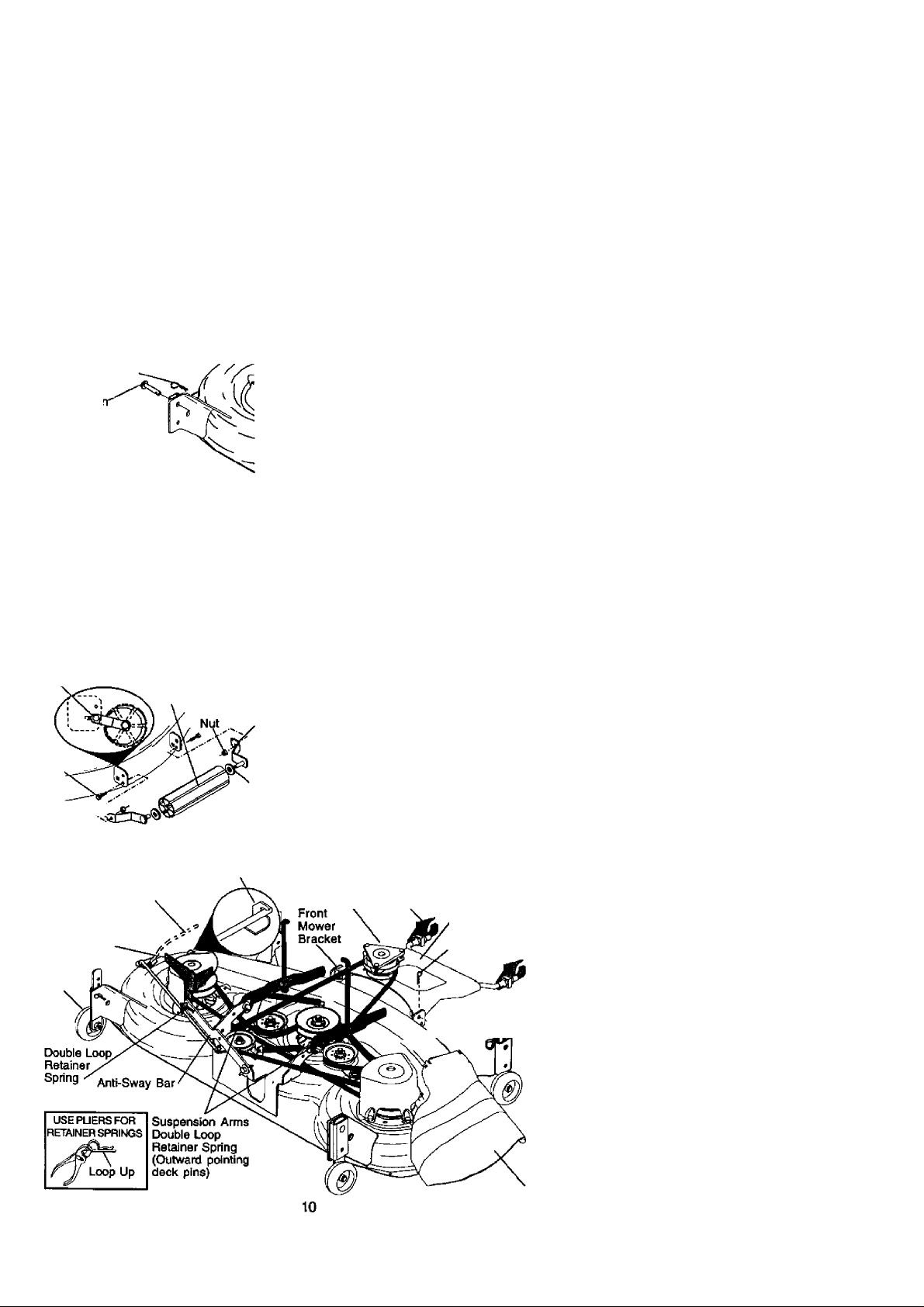
TO ATTACH NOSE ROLLER
1. Position brackets, 17/32 x 7/8 x 16
gauge washers, and nose rolier
between deck mounting brackets as
showm. Be sure to position brackets
on correct side, as shown.
2. Instail hex bolts and iock nuts as
shown. Tighten hardware secureiy.
NOTE; Be sure bracket tabs are posi
tioned In tab holes in deck brackets.
Tab Hole
Nose Roller
Hex Bolt
■A"
Bracket-liC
Lock
B' Bracket
Washer
INSTALL MOWER AND DRIVE BELT
Be sure tractor is on level surface and mower
suspension arms are raised with attachment
lift control. Engage parkirtg brake.
1. Cut and remove ties securing anti
sway bar and belts. Swing anti-sway
bar to left side of mower deck.
2. Slide mower under tractor with
deflector shield to right side of tractor.
IMPORTANT: Check belt lor proper
routing in all mower pulley grooves.
3. If equipped,turn height adjustment
knob counterclockwise until it stops.
4. Lower mower linkage with attachment
lift control.
5. Be sure belt tension rod is in disen
gaged position.
6. Install belt into electric clutch pulley
groove.
7. Place the suspension arms on
outward pointing deck pins. Retain
with double loop retainer ^ring with
loops up as shown.
8. Install front plate assembly to tractor
suspension brackets and retain with
single loop retainer springs as shown.
9. Position front plate assembly between
front mower brackets. Raise deck and
plate assembly to align holes and
insert flanged pins. Secure pins with
double loop retainer springs between
the plate assembly and mower
brackets.
Belt Tension Rod
Disengaged Position
Chassis
Bracket
Gauge
Wheel
Lock Bracket
Electric Front
Clutch Suspention
Pulley Brackets Front Plate
‘ ' Assembly
Double Loop
Retainer Springs
Flanged Retainer
Single
Loop
.....
a Springs
Deflector Shelld
Page 11

NOTE: To assist in locating hole in
flanged pin, the hole in pin is inline with
notch on head of pin. If necessary, move
mower side-to-side to give space
between plate and mower brackets.
IMPORTANT: Check belt for proper
routing in all mower pulley grooves.
10. Engage belt tension rod by pushing
rod into locking bracket.
^CAUTION: Belt tension rod is spring
loaded. Have a tight grip on rod and
engage slowly.
11 .Connect anti-sway bar to chassis
bracket under left footrest and retain
with double loop retainer spring.
12. If equipped, turn height adjustment
knob clockwise to remove slack from
mower suspension.
13. Raise deck to highest position.
14. Adjust gauge wheels before operating
mower as shown in the Operation
section of this manual.
CHECK TIRE PRESSURE
The tires on your tractor were overinflated
at the factory for shippirig purposes.
Correct tire pressure is important for best
cutting performance.
• Reduce tire pressure to PSl shovm in
“PRODUCT SPECIFICATIONS” section
of this manual.
CHECK MOWER LEVELNESS
For best cutting results, mower should be
properly leveled. See TO LEVEL MOWER
HOUSING” in the Senrice and Adjustments
section of this manual.
CHECK FOR PROPER POSITION OF ALL
BELTS
See the figures that are shown for replac
ing motion, mower drive, and mower blade
drive belts in the Sen/ice and Adjustments
section of this manual. Verify that the belts
are routed correctly.
CHECK BRAKE SYSTEM
After you learn how to operate your tractor,
check to see №at tiie brake is properly
adjusted. See TO ADJUST BRAKE" in the
Service and Adjustments section of this
manual.
V'CHECKUST
Before you operate and enjoy your new
tractor, we wish to assure that you receive
the best performance and satisfaction
from this quality product.
Please review the following checklist:
/ All assembly instructions have been
completed.
/ No remaining loose parts in carton.
/ Battery is properly prepared and
charged.(Minimum 1 hour at 6 amps).
/ Seat is adjusted comfortably and
tightened securely.
/ All tires are property inflated. (For
shipping purposes, the tires were
overinflated at the factory).
/ Be sure mower deck is properly leveled
side-to-side/front-to-rear for best cutting
results. (Tires must be properly inflated
for leveling).
✓ Check mower and drive belts. Be sure
they are routed property around pulleys
and inside all belt keepers.
/ Check wiring. See that all connections
are still secure and wires are properly
clamped.
While learning how to use your tractor,
pay extra attention to the following
important items:
/ Engine oil is at proper level.
/ Fuel tank is filled with fresh, clean,
regular unleaded gasoline.
/ Become familiar with ail controls - their
location and function. Operate them
before you start the engine.
/ Be sure brake system is in safe
operating condition.
11
Page 12

OPERATION
These symbols may appear on your tractor or in literature supplied with the product.
Learn and understand their meaning.
a
BATTERY
A
CAUTION OR
WARNING
|sii^
t
REVERSE
“fir
©
ENGINE ON
fl
FUEL
ATTACHMEMT REVERSE NEUTRAL HIGH LOW
CLUTCH ENGAGED
IGNITION CLUTCH DISENGAGED
ENGINE OFF
OIL PRESSURE
l\l jjiif
CHOKE
MOWER HEIGHT
R N
ATTACHMENT
LIGHTS ON OVER TEMP
©
PARKING BRAKE UNLOCKED
LOCKED
H L (d
KEEP AREA CLEAR SLOPE HAZARDS
(SEE SAFETY RULES SECTION)
FORWARD FAST
ai ©i
LIGHT
•m
i ^
MOWER LIFT
»1!
PARKING BRAKE
SLOW
la
I
If
DANGER, KEEP HANDS AND FEET AWAY
12
i ¿a
FREEINHEEL
(Automatic Modala only)
Page 13
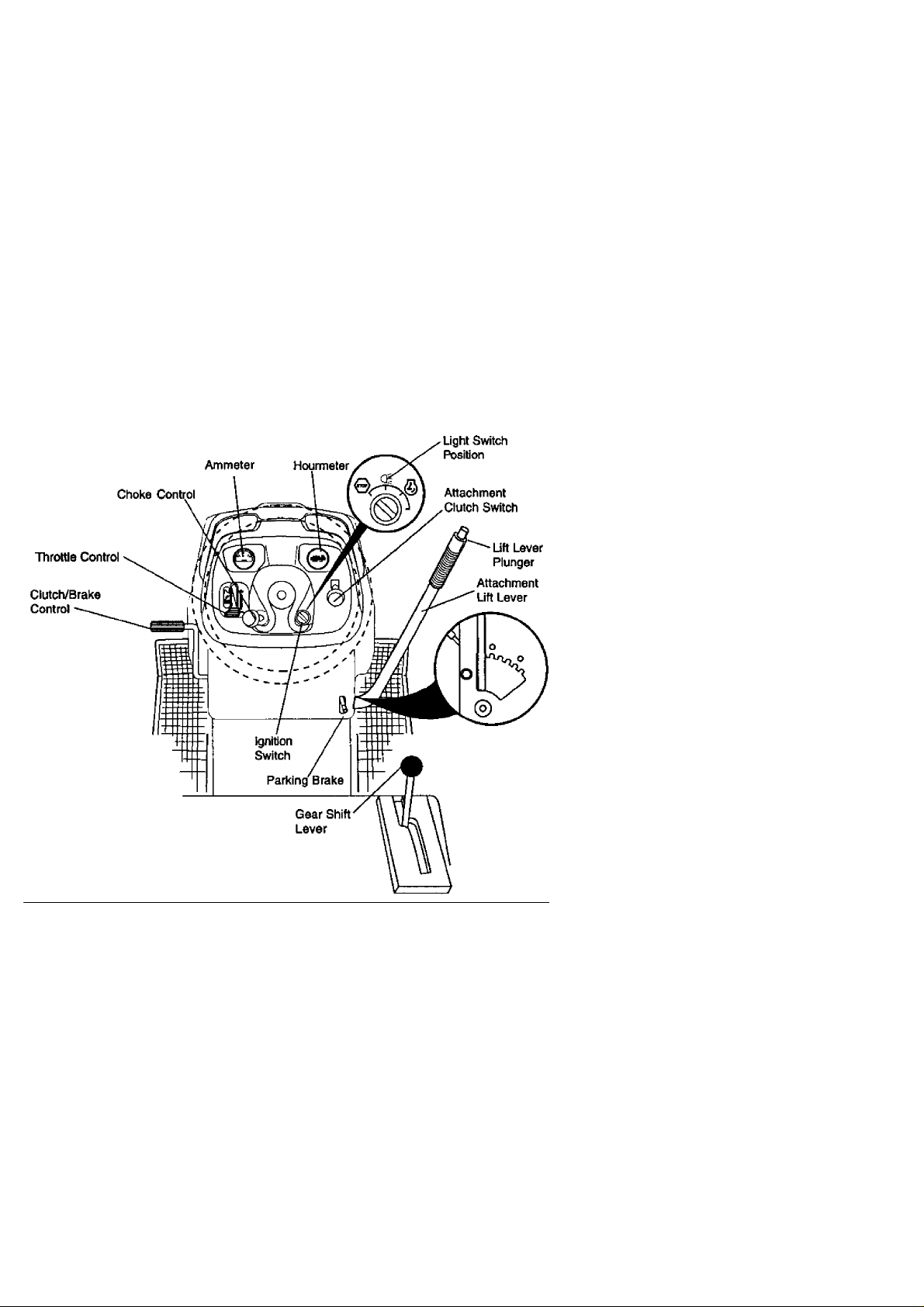
KNOWYOURTFiACTOR
READ THIS OWNER'S MANUAL AND SAFETY RULES BEFORE OPERATING
YOUR TRACTOR
Compare the illustrations with your tractor to familiarize yourself with the locations of
Our tractors conform to the safety standards of the
American National Standards Institute.
ATTACHMENT CLUTCH SWITCH: Used
to engage the mower blades, or other
attachments mounted to your tractor.
LIGHT SWITCH: Turns the headlights on
and off.
THROTTLE CONTROL- Used to control
engine speed.
CHOKE CONTROL - Used when starting
a cold engine.
CLUTCH/BRAKE PEDAL: Used for
declutching and braking the tractor and
starting the engine.
GEARSHIFT LEVER - Selects the speed
and direction of tractor.
13
ATTACHMENT LIFT LEVER - Used to raise,
lower, and adjust the mower deck or other
attachments mounted to your tractor.
LIFT LEVER PLUNGER: Used to release
attachment lift lever when changing its
position.
IGNITION SWITCH: Used for starting and
stopping the engine.
AMMETER: Indicates battery charging (+]
or discharging (-).
PARKING BRAKE: Locks clutch/brake
into the brake position.
HOURMETER - Indicates hours of operation.
Page 14

The operation of any tractor can result in foreign objects thrown into the
eyes, which can result in severe eye damage. Always wear safety glasses
or eye shields while operating your tractor or performing any adjustments
or repairs. We recommend a wide vision safety mask over spectacles, or
standard safety glasses.
HOWTO USEYOURTRACTOR
TO SET PARKING BRAKE
Your tractor is equipped with an operator
presence sensing switch. When engine
is running, any attempt by the operator to
leave the seat without first setting the
parking brake will shut off the engine.
1. Depress clutch/brake pedal into full
“Bf^KE" position and hold.
2. Place parking brake lever in “EN
GAGED” position and release
pressure from clutch/brake pedal.
Pedal should remain in “BRAKE"
position. Make sure parking brake will
hold tractor secure.
Choke “Disengaged” Switch PuHOi^o
Clutch/Brake
Pedal “Drive"
Position
Push-In to Attachment Clutch
Marking Brake
“Engaged” Position
“Disengaged"
Position
STOPPING
MOWER BLADES -
• To stop mower blades,move attach
ment clutch switch to “DISENGAGED”
position.
GROUND DRIVE -
• To stop ground drive, depress clutch/
brake pedal into full “BRAKE” position.
• Move gearshift lever to neutral (N)
position.
ENGINE-
• Move throttle control to slow position.
NOTE: Failure to move throttle control to
slow position and allowing engine to idle
before slopping may cause engine to
“backfire".
• Tum ignition key to “OFP position and
remove key. Always remove key when
leaving tractor to prevent unauthorized
use.
14
• Never use choke to stop engine.
IMPORTANT: Leaving the ignition switch
in any position other than “OFF" will
cause the battery to be discharged,
(dead).
NOTE: Under certain conditions when
tractor is standing idle with the engine
running, hot engine exhaust gases may
cause "browning” of grass. To eliminate
this possibility, always stop engine when
stopping tractor on grass areas.
^CAUTION: Always stop tractor com
pletely, as described above, before
leaving the operator's position; to empty
grass catcher, etc.
TO USE THROTTLE CONTROL
Always operate engine at full throttle.
• Operating engine at less than full
throttle reduces the battery charging
rate.
• Full throttle offers the best bagging and
mower performance.
TO USE CHOKE CONTROL
Use choke control whenever you are
starting a cold engine. Do not use to start
a warm engine.
■ To engage choke control, pull knob out.
Slowly push knob in to disengage.
TO MOVE FORWARD AND
BACKWARD
The direction and speed of movement is
controlled by the gearshift lever.
1. Start tractor with clutch/brake pedal
depressed and gearshift lever in
neutral (N) position.
2. Move gearshift lever to desired
position.
3. Slowly release clutch/brake pedal to
start movement.
IMPORTANT: Bring tractor to a complete
stop before shifting or changing gears.
Failure to do so will shorten the useful life
of your transaxle.
TO ADJUST MOWER CUTTING HEIGHT
The position of the attachment lift lever
determines the cutting height.
• Grasp lift lever.
■ Press plunger with thumb and move
lever to desired position.
Page 15

The cutting height range is approximalely 1-1/2 to 4". The heights are
measured from the ground to the blade
tip with the engine not running. These
heights are approximate and may vary
depending upon soil conditions, height of
grass and types of grass being mowed.
* The average lawn should be cut to
approximately 2-1/2 inches during the
cool season and to over 3 inches
during hot months. For healthier and
better looking lawns, mow often and
after moderate growth.
• For best cutting performance, grass
over 6 inches in height should be
mowed twice. Make the first cut
relatively high; the second to desired
height.
TO ADJUST GAUGE WHEELS
Gauge wheeis are properiy adjusted
when they are slightly off the ground
when mower is at the desired cutting
height In operating position. Gauge
wheels then keep the deck in proper
position to help prevent scalping in most
terrain conditions.
NOTE; Be sure tractor is on a flat level
surface.
1. Lower mower and adjust mower to
desired cutting height.
Remove retainer spring and clevis pin
2.
which secure each gauge wheel bar.
Lower gauge wheels to ground. Raise
3.
gauge wheels slightly to align holes in
bracket and gauge wheel bar and
insert clevis pin. Gauge wheels
should be slightly off the ground.
Replace retainer spring into clevis pin.
4.
Besure all gauge wheels are in the
5.
same setting.
IMPORTANT: № sure to readjust gauge
wheels if you change the cutting height
of the mower deck.
TO OPERATE MOWER
Your tractor is equipped with an operator
presence sensing switch. Any attempt by
the operator to leave the seat with the
engine running and the attachment clutch
engaged will shut off the engine.
1. Select desired height of cut.
2. Start mower blades by engaging
attachment clutch control.
TO STOP MOWER BLADES disengage attachment clutch control.
^CAUTION: Do not operate the mower
without either the entire grass catcher, on
mowers so equipped, or the deflector
shield in place.
Attachment Clutch Attachment Lift Lever
Swtch Pull Out To High Position
“Engage" ^
Push In To
'Disengage'
' Low
Position
Deflector
Shield
TO OPERATE ON HILLS
^CAUTION: Do not drive up or down
hills with slopes greater than 15° and do
not drive across any slope.
• Choose the slowest speed before
starting up or down hills.
• Avoid stopping or changing speed on
hills.
• If slowing is necessary, move throttle
control lever to slower position.
• If stopping is absolutely necessary,
push clutch/brake pedal quickly to
brake position and engage parking
brake.
• Move gearshift lever to 1st gear. Be
sure you have allowed room for tractor
to roll slightly as you restart movement.
• To restart movement, slowly release
parking brake and clutch/brake pedal.
• Make all turns slowly.
TO TRANSPORT
• Raise attachment lift to highest position
with attachment lift control.
• When pushing or towing your tractor,
be sure gearshift lever is in neutral (N)
position.
■ Do not push or tow tractor at more than
five (5) MPH.
15
Page 16

NOTE: To protect hood from damage
when transporting your tractor on a truck
or a trailer, be sure hood is closed and
secured to tractor. Use an appropriate
means of tying hood to tractor (rope, cord,
etc.).
TOWING CARTS AND OTHER ATTACH
MENTS
Tow only the attachments that are
recommended by and comply with
specifications of the manufacturer of your
tractor. Use common sense when towing.
Too heavy of a load, while on a slope, is
dangerous. Tires can lose traction with
the ground and cause you to lose control
of your tractor.
BEFORE STARTINGTHE ENGINE
CHECK ENGINE OIL LEVEL
The engine in your tractor has been
shipped, from the factory, already filled
with summer weight oil.
1. Check engine oil with tractor on level
ground.
2. Unthread and remove oil fill cap/
dipstick; wipe oil off. Reinsert the
dipstick Into the tube and rest oil fill
cap on the tube. Do not thread the
cap onto the tube. Remove and read
oli level. If necessary, add oil until
TULL" mark on dipstick is reached.
Do not overfill.
• For cold weather operation you should
change oil for easier starting (See “OIL
VISCOSITY CHART in the Mainte
nance section of this manual).
• To change engine oil, see the Mainte
nance section In this manual.
ADD GASOLINE
• Fill fuel tank. Use fresh, clean, regular
unleaded gasoline with a minimum of
87 octane. (Use of leaded gasoline will
increase carbon and lead oxide
deposits and reduce valve life). Do not
mix oil with gasoline. Purchase fuel in
quantities that can be used within 30
d№s to assure fuel freshness.
IMPORTANT: When operating in tem
peratures below 32“F(0°C), use fresh,
clean winter grade geisoline to help
insure good cold weather starting.
AwarninG: Experience indicates that
alcohol blended fuels (called gasohol or
using ethanol or methanol) can attract
moisture which leads to separation and
formation of acids during storage. Acidic
gas can damage the fuel system of an
engine while in storage. To avoid engine
problems, the fuel system should be
emptied before storage of 30 days or
lonqer. Drain the gas tank, start the
engine and let it run until the fuel lines
and carburetor are empty. Use fresh fuel
next season. See Storage Instmctions for
additional information. Never use engine
or carburetor cleaner products in the fuel
tank or permanent damage may occur.
AcAUTION: Rll to bottom of gas tank
filler neck. Do not overfill. Wipe off any
spilled oil or fuel. Do not store, spill or use
gasoline near an open flame.
TO START ENGINE
When starting the engine for the first time
or if the engine has run out of fuel, it will
take extra cranidng time to move fuel from
the tank to the engine.
1. Sit on seat In operating position,
depress clutch/brake pedal and set
parking brake.
Place gear shift lever in neutral (N)
2.
position.
Move attachment clutch to “DISEN
GAGED" position.
Move throttle control to fast position
4.
Pull choke control out for a cold
5.
engine start attempt. For a warm
engine start attempt the choke control
may not be needed.
NOTE: Before starting, read the warm and
cold starting procedures below,
6. Insert key into ignition and turn key
clockwise to “START position and
release key as soon as engine starts.
Do not run starter continuously for
more than fifteen seconds per minute.
If the engine does not start after
several attempts, push choke control
in, wait a few minutes and try again. If
engine still does not start, pull the
choke control out and retry.
WARM WEATHER STARTING (50" F and
above)
7. When engine starts, slowly push
choke control in until the engine
begins to run smoothly. If the engine
starts to run roughly, pull the choke
control out slightly for a few seconds
and then continue to push the control
in slowly.
16
Page 17

• The attachments and ground drive can
• When mowing large areas, start by
now be used. If the engine does not
accept the load, restart the engine and
allow it to warm up for one minute
using the choke as described above.
COLD WEATHER STARTiNG {50° F and
below)
7. When engine starts, siowiy push
• If grass is extremely tall, it should be
choke control in until the engine
begins to run smoothiy. Continue to
push the choke control in small steps
allowing the engine to accept small
changes in speed and load, until the
• Do not mow grass when it is wet. Wet
choke control is fully in. If the engine
starts to run roughly, pull the choke
control out slightly tor a few seconds
and then continue to push the control
• Always operate engine at full throttle
in slowly. This may require an engine
warm-up period from severai seconds
to several minutes, depending on the
temperature.
• The attachments can be used during
the engine warm-up period and may
r^uire the choke control be pulled out
• When operating attachments, select a
slightly.
NOTE: If at a high altitude (above 3000 feet)
or in cold temperatures (bdow 32 F) the
cartxjretor fuel mixture may need to be
adjusted for best engine performance. See
TO ADJUST CARBIIRET-OR" in the Service
and Adjustments section of this manual.
MOWINGTIPS
• Mower should be properly leveled for
best mowing performance. See TO
LEVEL MOWER HOUSING" in the
Service and Adjustments section of this
manual.
• The left hand side of mower should be
used for trimming.
• Drive so that clippings are discharged
onto the area that has been cut. Have
the cut area to the right of the tractor.
This will result in a more even distribu
tion of clippings and more uniform
cutting.
turning to the right so that clippings will
discharge away from shrubs, fences,
driveways, etc. After one or two rounds,
mow in the opposite direction making
left hand turns until finished.
mowed twice to reduce load and
possible fire hazard from dried clip
pings. Make first cut relatively high; the
second to the desired height.
grass will plug mower and leave
undesirable clumps. Allow grass to dry
before mowing.
when mowing to assure better mowing
performance and proper discharge of
material. Regulate ground speed by
selecting a low enough gear to give the
mower the best cutting performance as
well as the quality of cut desired.
ground speed that will suit the terrain
and give best performance of the
attachment being used.
17
Page 18
MAINTENANCE
MAINTENANCE SCHEDULE
FILL IN DATES
AS YOU COMPLETE
REGULAR SERVICE SERVICE DATES
Check Brake Operation
Check Tire Pressure
Check Operalor Presence and
Interlock Sysiems
Check for Loose Fasteners
ShaipeiVHepla« Mower Blades
Lubrication Chart
Check Banery Level
Clean Batteiy and Tarmlnale
Check Transaxle Cooling
Ad|u$t Blade Bett(s) Tertaion
AdtuBi Motion Drtva Bett(s) Ter>sion
Check Engirw Oil Level
Change Engine OM
Cteen Air Filer
Clean Air Screen
Inspect Muffler/Spark Arrester
Replace Oil Filter (№ equipped)
Clean Engine Cooling Rns
Replace Spark Plug
Replace Air Fitter Paper Cartridge
Replace Fuel Ritef
1 < Chftng* mor* oDm when op*r«ting <jixl*r • load or In high
2 * Swvica rrwKa ofl*n whan opanling In dkty or duaty condWona.
a' H aquippad wMv oN Mar, ehanga ad avary 50 houra.
4' Rapiaca Midaa mora oAan w4ian mowing In aandy aoN.
GENERAL RECOMMENDATIONS
The warranty on this tractor does not
cover items that have been subjected to
operator abuse or negligence. To receive
full value from the warranty, operator must
maintain tractor as instructed in this
manual. Some adjustments will need to
be made periodically to properly maintain
your tractor.
All adjustments in the Service and
Adjustments section of this manual
should be checked at least once each
season.
• Once a year you should replace the
spark plug, clean or replace air filter,
and check blades and belts for wear. A
new spark plug and clean air filter
assure proper air-fuel mixture and help
your engine run better and last longer.
BEFORE EACH USE
1. Check engine oil level.
2. Check brake operation.
3. Check tire pressure.
4. Check operator presence and
interlock systems for proper operation.
5. Check for loose fasteners.
✓ ✓
✓ ✓
✓
✓
✓
✓ t
✓
✓
✓
✓
✓
|r>4.!
✓ a
✓ ✓
✓ 2
tompmtiJFH. S - H •qglppMiwIlh K|uatabl» lytMm.
✓
✓
✓
✓
1«^
d - Nm r*qulf*d 2 «quipped «riPi m«in4«n«ne«-h«« PaMry.
7 - Irort Ml« pivoi boN to SS tL-lb«. iviMfmum.
Do rwt ov«4tlflh(«n.
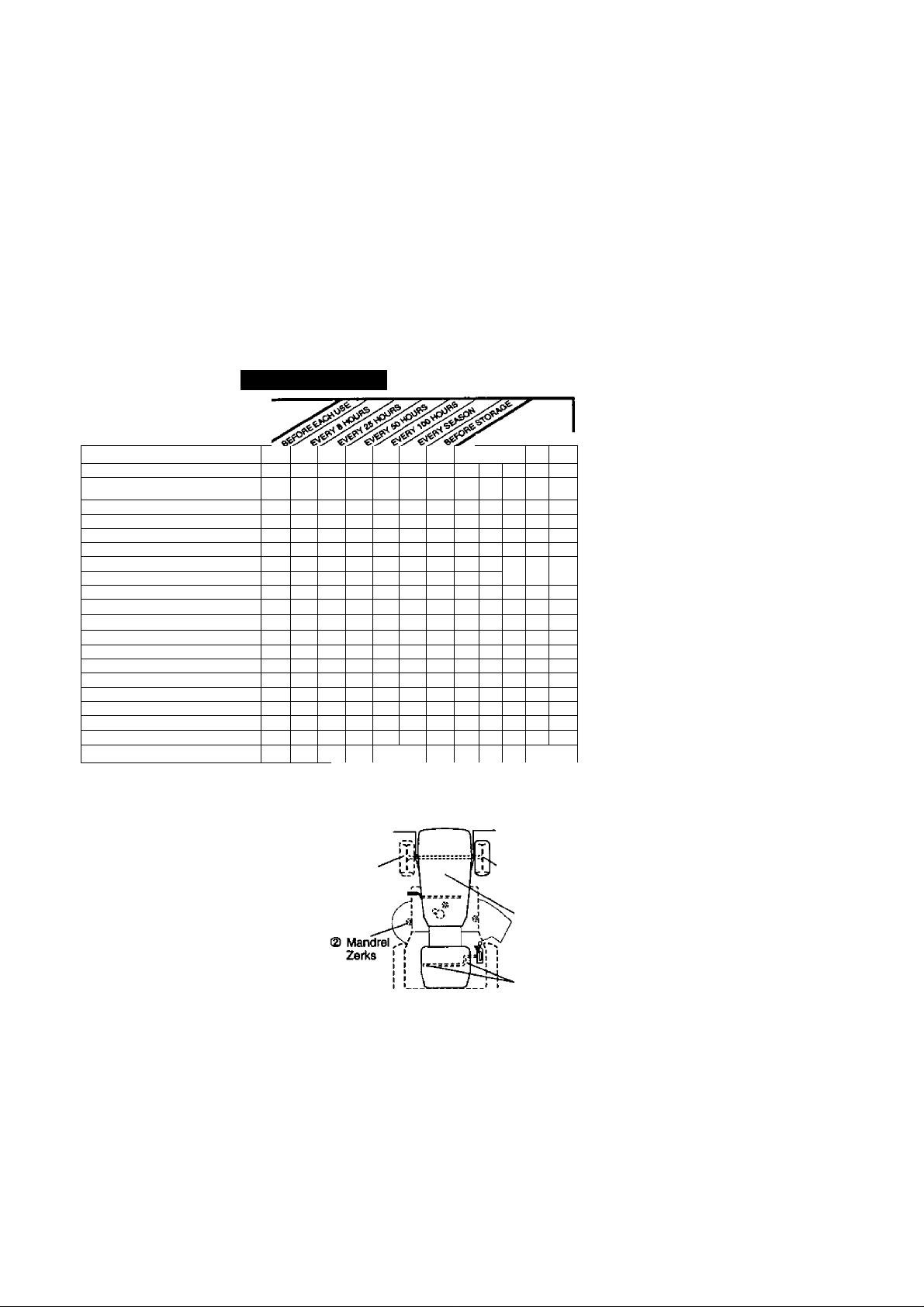
LUBRICATION CHART
® Spindle
Zerk
@ Front
Wheel
Bearing
Zetk
0 SAE 30 or 10w30 Motor Oil
® General Purpose Grease
® Refer to Mainterunce “ENGINE” Section
® Spindle
® Front Wheel
L--' Pivots
IMPORTANT: Do not oil or grease the
pivot points which have special nylon
bearings. Viscous lubricants will attract
dust and dirt that will shorten the life of
the self-lubricating bearings. If you feel
they must be lubricated, use only a dry,
powered graphite type lubricant
sparingly.
_L_
Zerk
Bearing
Zerk
® Engine
0 Gearshift
18
Page 19

TRACTOR
Always observe safety rules when
performing any maintenance.
BRAKE OPERATION
If tractor requires more than six (6) feet
stopping distance at high speed in
highest gear, then brake must be ad
justed. (See TO ADJUST BRAKE” in the
Service and Adjustments section of this
manual).
TIRES
• Maintain proper air pressure in all tires
(See “PRODUCT SPECIFICATIONS”
section of this manual).
• Keep tires free of gasoline, oil, or insect
control chemicals which can harm
rubber.
• Avoid stumps, stones, deep ruts, sharp
objects and other hazards that may
cause tire damage.
NOTE: To seal tire punctures and prevent
fiat tires due to slow leaks, tire sealant
may be purchased from your local parts
dealer. Tire sealant also prevents tire dry
rot and corrosion.
OPERATOR PRESENCE SYSTEM
Be sure that operator presence and
interlocdt systems are working properly. If
your tractor does not function as de
scribed below, repair the problem
immediately.
■ The engine should not start unless the
brake (^al is fully depressed and
attachment clutch control is in the
disengaged position.
• When the engine is running, any
attempt by the operator to leave the
seat without first setting the parking
brake should shut off the engine.
• When the engine is running and the
attachment clutch is engaged, any
attempt by the operator to leave the
seat should shut off the engine.
• The attachment clutch should never
operate unless the operator is in the
seat.
BLADE CARE
For best results mower blades must be
kept sharp. Replace bent or damaged
blades.
BLADE REMOVAL
1. Raise mower to highest position to
allow access to blades.
2. Remove hex tx>lt, lock washer and flat
washer securing blade.
3. Install new or resharpened blade with
trailing edge up towards deck as
shown.
IMPORTANT: To ensure proper assembly,
center hole in blade must align with star
on mandrel assembly.
4. Reassemble hex bolt, lock washer
and flat washer in exact order as
shown,
5. Tighten bolt securely (45-55 Ft. Lbs.
torque).
IMPORTANT: Blade bolt is Grade 8 heat
treated.
Trailing Assembly
Edge Ups^ Hade '
Rat Washer
Lock Washerv x, „ ,
Hex Boltv.^ Ce
(Grade Hole
*A Grade 8 Heat Treated Bolt Can Be
Identified By Six Unes On The Bolt Head
Mandrel
TO SHARPEN BLADE
NOTE: We do not recommend sharpen
ing blade, but if you do, be sure the blade
is balanced.
Care should be taken to keep the blade
balanced. An unbalanced blade will
cause excessive vibration and eventual
damage to mower and engine.
• The blade can be sharpened with a file
or on a grinding wheel. Do not attempt
to sharpen while it is on the mower.
• To check blade balance, you will need
a 5/8" diameter steel bolt, pin, or a cone
balancer. (When using a cone bal
ancer, follow the instructions supplied
with balancer).
NOTE: Do not use a nail (or balancing
blade. The lobes of the center hole may
appear to be centered, but are not.
• Slide blade onto an unthreaded portion
of the steel bolt or pin and hold the bolt
or pin parallel with the ground. If blade
is balanced, it should remain in a
horizontal position. If either end of the
blade moves downward, sharpen the
heavy end until the blade is balanced.
Page 20

BATTERY
Your tractor has a battery charging system
which is sufficient for normal use. How
ever, periodic charging of the battery with
an automotive charger will extend its life.
• Keep battery and terminals clean.
• Keep battery bolts tight.
• Keep small vent holes open.
• Recharge at 6-10 amperes for 1 hour.
NOTE: The original equipment battery on
your tractor is maintenance free. Do not
attempt to open or remove caps or covers.
Adding or checking level of electrolyte is
not necessary.
TO CLEAN BATTERY AND TERMINALS
Corrosion and dirt on the battery and
terminals can cause the battery to “leak”
Change the oil after every 50 hours of
operation or at least once a year if the
tractor is not used for 50 hours in one
year.
Check the crankcase oil level before
starting the engine and after each eight
(8) hours of operation. Tighten oil fill cap/
dipstick securely each time you check the
oil level.
TO CHANGE ENGINE OIL
Determine temperature range expected
before oil change. All oil must meet API
service classification SF-SJ.
• Be sure tractor is on level surface.
• Oil will drain more freely when warm.
• Catch oil in a suitable container.
1. Remove oil fill cap/dipstick. Be careful
power.
1. Remove terminal guard.
2. Disconnect BLACK battery c^le first
2. Remove cap from end of drain valve
then RED battery cable and remove
battery from tractor.
3. Rinse the battery with plain water and
dry.
4. Clean terminals and battery cable
ends with wire brush until bright.
3. Unlock drain valve by pushing inward
4. To open, pull out on the drain valve.
5. After oil has drained completely, close
5. Coat terminals with grease or petro
leum jelly.
6. Reinstall battery (See “REPLACING
BATTERY' in the SERVICE AND
6. Remove the drain tube and replace
ADJUSTMENTS section of this
manual).
V-BELTS
7. Refill engine with oil through oil fill
Check V-belts for deterioration and wear
after 100 hours of operation and replace
if necessary. The belts are not adjustable.
Replace belts if they begin to slip from
wear.
TRANS AXLE COOLING
Keep transaxle free from build-up of dirt
and chaff which can restrict cooling.
ENGINE
LUBRICATION
Only use high quality detergent oil rated
with API service classification SF-SJ.
Select the oil's SAE viscosity grade
according to your expected operating
temperature.
SAE VISCOSITY GRADES
I I I
ao 32 40
c
____________
-ao -w
TEXyEnATOPE RANGE AMTXaPATED BEFORE NEXT OIL CHANGE
____________H________no______
.Ml
W_______30 *0
iOD
20
not to allow dirt to enter the engine
when changing oil.
and Install the drain tube onto the
fitting.
slightly and turning counterclockwise.
and lock the drain valve by pushing
inward and turning clockwise until the
pin is in the locked position as shown.
the cap onto to the end of the drain
valve.
dipstick tube. Pour slowly. Do not
overfill. For approximate capacity see
“PRODUCT SPECIFICATIONS"
section of this manual.
8. Use gauge on oil fill cap/dipstick for
checking level. Insert dipstick Into the
tube and rest the oil fill cap on the
tube. Do not thread the cap onto the
tube when taking reading. Keep oil
at “FULL” line on dipstick. Tighten cap
onto the tube securely when finished.
Oil Drain Valve
Closed
and
Locked
Position
Cap
Drain Tube
Page 21

CLEAN AIR SCREEN
Air screen must be kept free of dirt and
chaff to prevent engine damage from
overheating. Ciean iwith a wire brush or
compressed air to remove dirt and
stubborn dried gum fibers.
CLEAN AIR INTAKE/COOLING AREAS
To insure proper cooling, make sure the
grass screen, cooling fins, and other
extemai surfaces of the engine are kept
clean at all times.
Every 100 hours of operation (more often
under extremely dusty, dirty conditions),
remove the blower housing and other
cooling shrouds. Clean the cooling fins
and external surfaces as necessary. Make
sure the cooling shrouds are reinstalled.
NOTE: Operating the engine with a
blocked grass screen, dirty or plugged
cooling fins, and/or cooling shrouds
removed will cause engine damage due
to overheating.
AIR FILTER
Your engine will not run properly using a
dirty air filter. Clean the foam pre-cleaner
after every 25 hours of operation or every
season. Service paper cartridge every
100 hours of operation or every season,
whichever occurs first.
Service air cleaner more often under
dusty conditions.
1. Loosen knob and remove cover.
TO SERVICE PRE-CLEANER
2. Slide foam pre-cleaner off cartridge.
3. Wash it in liquid detergent and water.
4. Squeeze it dry in a clean cloth. Allow
it to dry.
5. Saturate it in engine oil. Wrap it in
clean, absorbent cloth and squeeze to
remove excess oil.
TO SERVICE CARTRIDGE
• Replace a dirty, bent, or damaged
cartridge.
NOTE: Do not wash the paper cartridge
or use pressurized air, as this will
damage the cartridge.
6. Remove nut and cartridge plate.
7. Reinstall the pre-cteaner (cleaned
and oiled) over the paper cartridge.
8. Check rubber seal for damage and
proper position around stud. Replace
if necessary.
9. Reassemble air cleaner, cartridge
plate, and nut.
10. Reinstall air cleaner cover and secure
by tightening knob.
2^ engine life.
Knob ■
ENGINE OIL FILTER
Replace the engine oil filter every season
or every other oil change if the tractor is
used more than 100 hours in one year.
MUFFLER
Inspect and replace corroded muffler and
spark arrester (if equipped) as it could
create a fire hazard and/or damage.
SPARK PLUGS
Replace spark plugs at the beginning of
each mowing season or after every 100
hours of operation, whichever occurs first.
Spark plug type and gap setting are
shown in “PRODUCT SPECIFICATIONS”
section of this manual.
IN-LINE FUEL FILTER
The fuel filter should be replaced once
each season. If fuel filter becomes
clogged, obstructing fuel flow to carbure
tor, replacement is required.
1. With engine cool, remove filter and
plug fuel line sections.
2. Place new fuel filter in position in fuel
line with arrow pointing towards
carburetor.
3. Be sure there are no fuel line leaks
and clamps are properly positioned.
4. Immediately wipe up any spilled
gasoline.
Clamp
Clamp
Fuel RIter
CLEANING
• Clean engine, battery, seat, finish, etc.
of all foreign matter.
• Keep finished surfaces and wheels free
of all gasoline, oil, etc.
• Protect painted surfaces with automo
tive type wax.
We do not recommend using a garden
hose to clean your tractor unless the
electrical system, muffler, air filter and
carburetor are covered to keep water out.
Water in engine can result in a shortened
Page 22

SERVICE AND ADJUSTMENTS
CAUTION: BEFORE PERFORMING ANY SERVICE OR ADJUSTMENTS:
1. Depress clutch/brake pedal fully and set parking brake.
2. Place gearshift lever In neutral (N) position.
3. Place attachment clutch in “DISENGAGED” position.
4. Turn ignition key “OFP and remove key.
5. Make sure the blades and all moving parts have completely stopped.
6. Disconnect spark plug wire from spark plug and place wire where it cannot
come in contact with plug.
TRACTOR
TO REMOVE MOWER
1. Place attachment clutch in “DISEN
GAGED" position.
2. If equipped, turn height adjustment
knob to lowest setting.
3. Lower mower to Its lowest position.
4. Disengage belt tension rod from lock
bracket.
^CAUTION: Rod is spring loaded. Have
a tight grip on rod and relesise slowly.
5. Remove retainer spring holding anti-
swaybar to chassis bracket and
disengage anti-swaybar from bracket.
6. Remove four retainer springs from
front plate assembly and remove
plate.
7. Remove retainer springs from
suspension arms at deck and disen
gage arms from deck.
8. Raise attachment lift to its highest
position.
9. Slide mower forward and remove belt
from electric clutch pulley.
10. Slide mower out from under right side
of tractor.
Suspension
Belt Tension Rod
(Disengaged
Position)-^ I'
Chassis /
BracketaI
Retainer
Spring
Anti-Sway
Bar
Arms
________________________________
TO INSTALL MOWER
Follow procedure described in “INSTALL
MOWER AND DRIVE BELT in the
Assembly section of this manual.
TO LEVEL MOWER HOUSING
Adjust the mower while tractor is parked
on level ground or driveway. Make sure
tires are properly inflated (See “PROD
UCT SPECIFICATIONS" section of this
manual). If tires are over or
underinflated, you will not properly adjust
your mower,
SIDE-TO-SIDE ADJUSTMENT
■ Raise mower to its highest position.
• At the midpoint of both sides of mower,
measure height from bottom edge of
mower to ground. Distance "A" on
both sides of mower should be the
same or within 1/4" of each other.
• If adjustment is necessary, make
adjustment on one side of mower only.
• To raise one side of mower, tighten lift
link adjustment nut on that side.
• To lower one side of mower, loosen lift
link adjustment nut on that side.
Electric
Clutch Pulley
Front
Plate
Assembly
Retainer Springs
(Both Sides)
Front Mower
Bracket
Page 23

NOTE: Each full turn of adjustment nut
will change mower height about 1/8“.
• Recheck measurements after adjust
ing.
Bottom Edge of
Mower to Ground
Bottom Edge of
. Mower to Ground
Lift Unk
Adjustment
Nut
FRONT-TO-BACK ADJUSTMENT
IMPORTANT: Deck must be level slde-to-
side.lf the following front-to-back adjust
ment is necessary, be sure to adjust both
front links equally so mower will stay
level side-to-side.
To obtain the best cutting results, the
mower housing should be adjusted so
that the front is approximately 1/8“ to 1/2“
lower than the rear when the mower is in
its highest position.
Check adjustment on right side of tractor.
Measure distance “D" directly in front and
behind the mandrel at bottom edge of
mower housing as shown.
• Before making any necessary adjust
ments, check that both front links are
equal in length.
• If links are not equal in length, adjust
one link to same length as other link.
• To lower front of mower loosen nut “E"
on both front links an equal number of
turns.
• When distance “D” is 1/8“ to 1/2“ lower
at front than rear, tighten nuts “P
against trunnion on both front links.
• To raise front of mower, loosen nut “P
from trunnion on both front links.
Tighten nut “E” on both front links an
equal number of turns.
• When distance “D” is 1/8“ to 1/2“ lower
at front than rear, tighten nut “P against
trunnion on both front links.
• Recheck side-to-side adjustment.
Blade
TO REPLACE MOWER DRIVE BELT
MOWER DRIVE BELT REMOVAL
1. Park tractor on a level surface.
Engage parking brake.
2. Lower mower to its lowest position.
3. Disengage belt tension rod from lock
bracket.
j&CAUTION: Rod Is spring loaded. Have
a firm grip on rod an release slowly.
4. Remove screws from R.H. mandrel
cover and remove cover.
Remove any dirt or grass clippings
5.
which may have accumulated around
mandrels and entire upper deck
surface.
Disconnect R.H. suspension arm from
6.
rear deck bracket by removing
retainer spring.
Carefully roll belt over the top of R.H.
7.
mandrel pulley.
Remove belt from electric clutch
8.
pulley.
Remove belt from idler pulleys.
9.
10. Check primary Idler arm and two
idlers to see that they rotate freely.
11. Be sure spring is securely hooked to
primary Idler arm and spring arm.
23
Page 24

MOWER DRIVE BELT INSTALLATION
12. Install belt in both idlers.
13. Install new belt onto electric clutch
pulley.
14. Carefully roll belt into upper groove of
R.H. mandrel pulley.
15. Carefully check belt routing making
sure belt is In the grooves correctly.
16. Reconnect R.H. suspension arm to
rear deck bracket with retainer spring.
17. Reassemble R.H. mandrel cover.
18. Engage belt tension rod by pushing
rod into locking bracket
Belt Tension Rod „ j, t'
V’
/ Pulleys t /
Spring
Arm '
R.H. Suspension AmT'
Primary Idler Ami'
TO REPLACE MOWER BLADE DRIVE
BELT
Park the tractor on level surface. Engage
parking brake.
1. Remove mower drive belt (See TO
REPLACE MOWER DRIVE BELT in
this section of this manual).
2. Remove mower (See TO REMOVE
MOWER" in this section of this manual).
3. Remove screws from LH. mandrel
cover and remove cover.
4. Carefully roll belt off LH. mandrel
pulley.
5. Remove belt from center mandrel
pulley, idler pulley, and R.H. mandrel
pulley.
6. Remove any dirt or grass which may
have accumulated around mandrels
and entire upper deck surface.
7. Check secondary idler arm and idler
pulley to see that they rotate freely.
8. Be sure spring is hooked in secondary
idler arm and secondary spring arm.
9. Install new belt in lower groove of R.H.
mandrel pulley, idler pulley, and center
mandrel pulley as shown.
10. Carefully roll belt over LH. mandrel
pulley. Make sure belt is in all grooves
properly.
24
11. Reinstall LH. mandrel cover.
12. Reinstall mower to tractor (See
"INSTALL MOWER AND DRIVE BELT
in the Assembly section of this manual).
13. Reassemble mower drive belt (See
TO REPLACE MOWER DRIVE BELT
in this section of this manual).
L.H. Mandrel
idler Pulley''
Center Mandrel
SecorKfary Idler Arm
' .-Spring
R.H. Mandrel
Secondary
Spring Arm
TO ADJUST BRAKE
Your tractor is equipped vrith an adjustable
brake system which is mounted on the
side of the transaxle.
If tractor requires more than six (6) feet
stopping distance at high speed in highest
gear on a level dry concrete or paved
surface, then brake must be adjusted.
1. Depress clutch/brake pedal and
engage parking brake.
2. Measure distance between brake
operating arm and nut “A” on brake rod.
3. If distance is other than 1-1/2", loosen
jam nut and turn nut “A” until distance
becomes 1-1/2". Retighten jam nut
against nut “A”.
4. Road test tractor for proper stopping
distance as stated above. Readjust if
necessary. If stopping distarKe is still
greater than six (6) feet in highest gear,
further maintenance is necessaiy.
Contact a Sears or other qualified
service center.
WfTH PARKING BRAKE “ENGAGED”
Page 25

TO REPLACE MOTION DRIVE BELT
Park the tractor on level surface. Engage
parking brake. For assistance, there Is a
belt Installation guide decal on bottom
side of left footrest.
1. Remove moiwer (See TO REMOVE
MOWER” in this section of this
manual.)
Disconnect clutch wire harness.
Remove clutch locator.
Remove belt from stationary idler and
clutching idler.
Pull belt slack toward rear of tractor.
Remove belt upwards from transaxle
pulley by deflecting beit keepers.
6.
Pull belt toward front of tractor and
remove downwards from around
electric clutch.
Install new belt by reversing above
7.
procedure.
TRANSAXLE GEAR SHIFT LEVER
NEUTRALADJUSTMENT
The transaxle should be in neutral when
the gear shift lever is in neutral (N) (lock
gate) position. The adjustment is preset at
the factory; however, if adjustment is
needed, proceed as follows;
1. Make sure transaxle Is In neutral (N).
NOTE: When die tractor rear wheels
move freely, the transaxte is in neutral.
2. Loosen adjustment bolt in front of the
right rear wheel.
3. Position the gear shift lever in the
neutral (N) position.
4. Tighten adjustment bolt securely.
NOTE: If additional clearance is needed
to get to adjustment bolt, move mower
deck height to the lowest position.
Gearshift Lever
'Adjustment Bolt Lock
Neutral
Gate
TO ADJUST STEERING WHEEL ALIGN
MENT
If steering wheel crossbars are not
horizontal (left to right) when wheels are
positioned straight fonward, remove
steering wheel and reassemble per
instructions in the Assembly section of
this manual.
FRONT WHEEL TOE-IN/CAMBER
The front wheel toe-in and camber are
not adjustable on your tractor. If damage
has occurred to affect the front wheel toein or camber, contact your nearest Sears
or other qualified service center.
TO REMOVE WHEEL FOR REPAIRS
1. Block up axle securely.
2. Remove axle cover, retaining ring and
washers to allow wheel removal (rear
wheel contains a square key - Do not
lose).
3. Repair tire and reassemble.
NOTE: On rear wheels only: align
grooves in rear wheel hub and axle.
Insert square key.
4. Replace washers and snap retaining
ring securely In axle groove.
5. Replace axle cover.
NOTE: To seal tire punctures and prevent
flat tires due to slow leaks, tire sealant
may be purchased from your local parts
dealer. Tire sealant also prevents tire dry
rot and corrosion.
Retaining Ring '
Axle
Square Key (Re^
Wheel Only)
Washers
25
Page 26

TO START ENGINE WITH AWEAK
BATTERY
ikCAUTION: Lead-acid batteries
generate explosive gases. Keep sparks,
name and smoking materials away from
batteries. Always wear eye protection
when around batteries.
If your battery is too weak to start the
engine, it should be recharged. (See
•BATTERY" in the MAINTENANCE
section of this manual).
If “jumper cables" are used for emergency
starting, follow this procedure:
IMPORTANT; Vbur tractor is equipped
with a 12 volt negative grounded system.
The other vehical must also be a 12 volt
negative grounded system. Do not use
your tractor battery to start other vehicles.
TO ATTACH JUMPER CABLES -
1. Connect each end of the RED cable to
the POSITIVE {+) terminal of each
battery, taking care not to short
against chassis.
Connect one end of the BLACK cable
2.
to the NEGATIVE (-) terminal of fully
charged battery.
Connect the other end of the BLACK
3.
cable to good CHASSIS GROUND,
away from fuel tank and battery.
TO REMOVE CABLES, REVERSE
ORDER -
1. BLACK cable first from chassis and
then from the fully charged battery.
2. RED cable last from both batteries.
REPLACING BATTERY
^CAUTION: Do not short battery
terminals by allowing a wrench or any
other object to contact both terminals at
the same time. Before connecting battery,
remove metal bracelets, wristwatch
bands, rings, etc.
Positive terminal must be connected first
to prevent sparking from accidental
grounding.
26
1.
Lift hood to raised position.
2.
Remove terminal guard.
Disconnect BLACK battery cable then
3.
RED battery cable and carefully
remove battery from tractor.
4.
Install new battery with terminals in
same position as old battery.
Reinstall terminal guard.
5.
First connect RED battery cable to
6.
positive (+) battery terminal with hex
bolt and keps nut as shown. Tighten
securely.
Connect BLACK grounding cable to
7.
negative (-) battery terminal with
remaining hex bolt and keps nut.
Tighten securely
Close terminal access doors.
Close hood.
Ksps Nut
Terminal
Access ,■■■
Door '
Terminal
Guard
Hex Bolt
Positive (Red)
Cable
Negative
(Black) Cable
TO REPLACE HEADLIGHT LAMP
^CAUTION: When lit, the halogen lamps
get extremely hot. Hold lamp assembly by
the holder and do not touch the bulb.
1. Raise hood.
2. Disconnect harness from lamp
assembly.
3. Rotate counterclockwise and pull
lamp assembly out of the hole in the
backside of the grill.
4. Insert new lamp assembly and rotate
clockwise to lock.
5. Reconnect harness to lamp assembly.
6. Close hood.
INTERLOCKS AND RELAYS
Loose or damaged wiring may cause
your tractor to run poorly, stop running, or
prevent it from starting.
• Check wiring. See electrical wiring
diagram in the Repair Parts section.
TO REPLACE FUSE
Replace with 20 amp automotive-type
plug-in fuse. The fuse holder is located
behind the dash.
Page 27

TO REMOVE HOOD AND GRILL ASSEMBLY
1. Raise hood,
2. Unsnap headlight wire connector.
3. Stand in front of tractor. Grasp hood at
sides, tilt toward engine and lift off of
tractor.
To replace, reverse above procedure.
4.
ENGINE
Maintenance, repair, or replacement of
the emission control devices and sys
tems, which are being done at the
customers expense, may be performed
by any non-road engine repair establish
ment or individual. Warranty repairs must
be performed by an authorized engine
manufacturer's service outlet.
TO ADJUST THROTTLE CONTROL
CABLE
The throttle control has been preset at the
factory and adjustment should not be
necessary. Check adjustment as de
scribed below before loosening cable. If
adjustment is necessary, proceed as
follows:
1. With engine not running, move throttle
control lever to fast position.
2. Check that speed control lever is
against stop screw. If it is not, loosen
casing clamp screw and pull throttle
cable until lever is against screw.
Tighten clamp screw securely.
idle Fuel Adjusting
Needle
Stop Screw
Idle Speed
Adjusting
Screw
Throttle
Control
Cable
Choke
.Contrd
,5/ Cable
TO ADJUST CHOKE CONTROL
The choke control has been preset at the
factory and adjustment should not be
necessary, check adjustment as de
scribed below before loosening cable. If
adjustment is necessary, proceed as
follows:
1. With engine not running, move choke
control (located on dash panel) to full
choke position.
2. Remove air cleaner cover, filter and
cartridge plate to expose carburetor
choke (See “AIR FILTER” in the
Maintenance section of this manual).
3. Choke should be closed. If it is not,
loosen casing clamp screw and move
choke cable until choke is completely
closed. Tighten casing clamp screw
securely.
4. Reassemble air cleaner.
27
Page 28

TO ADJUST CARBURETOR
The carburetor has been present at the
Jactory and adjustment should not be
necessary. However, minor adjustment
may be required to compensate for
differences in fuel, temperature, altitude
or load. If the carburetor does need
adjustment, proceed as follows:
In general, turning the adjusting needles
In (clockwise) decreases the supply of
fuel to the engine giving a leaner fuel/air
mixture. Turning the adjusting needles out
(counterclockwise) increases the supply
of fuel to the engine giving a richer fuel/
air mixture.
IMPORTANT: Damage to the needles
and the seats in carburetor may result if
screw is turned in too tight.
PRELIMINARY SETTING -
1. Be sure you have a clean air filter, and
the throttle control cable is adjusted
properly (see TO ADJUST
THROTTLE CONTROL CABLE" in the
Service and Adjustments section of
this manual).
2. With engine off turn Idle fuel adjusting
needle In (clockwise) closing it finger
tight and then turn out (counterclock
wise) 1 turn.
FINAL SETTING-
1. Start engine and allow to warm for five
minutes. Make final adjustments with
engine running and shift/motion
control lever in neutral (N) position.
NOTE: The high idle is set at the factory
and cannot be adjusted.
2. Idle speed setting - With throttle
control lever in slow position, engine
should idle at 1200 RPM. If engine
idles too slow or fast, turn Idle speed
adjusting screw in or out until correct
idle is attained.
3. Idle fuel needle setting - With throttle
control lever in slow position, turn idle
fuel adjusting needle In (clockwise)
until engine speed decreases and
then turn out (counterclociwise)
approximately 3/4 turn to obtain the
best low speed performance.
4. Recheck idle speed. Readjust if
necessary,
ACCELERATION TEST -
5. Move throttle control lever from slow to
fast position. If engine hesitates or
dies, turn idle fuel adjusting needle
out (counterclockwise) 1/8 turn.
Repeat test and continue to adjust, if
necessary, until engine accelerates
smoothly.
High speed stop is factory adjusted. Do
not adjust-damage may result.
IMPORTANT: Never tamper with the
engine governor, which is factory set for
proper engine speed. Overspeeding the
engine above the factory high speed
setting can be dangerous. If you think the
engine-governed high speed needs
adjusting, contact a Sears or other qualified
service renter, which has proper equip
ment and experience to make any
necessary adjustments.
28
Page 29

STORAGE
Immediately prepare your tractor for
storage at the end of the season or if the
tractor will not be used for 30 days or
more.
ACAUTION: Never store the tractor with
gasoiine in the tank inside a building
where fumes may reach an open flame or
spark. Allow the engine to cool before
storing In any enclosure.
TRACTOR
Remove mower from tractor for winter
storage. When mower is to be stored for
a period of time, clean it thoroughly,
remove all dirt, grease, leaves, etc. Store
in a clean, dry area.
1. Clean entire tractor (See “CLEANING"
in the Maintenance section of this
manual).
2. Inspect and replace belts, if necessary
(See belt replacement instmctions in
the Senrice and Adjustments section
of this manual).
3. Lubricate as shown in the Mainte
nance section of this manual.
4. Be sure that all nuts, bolts and screws
are securely fastened. Inspect moving
parts for damage, breakage and wear.
Replace if necessary.
5. Touch up all rusted or chipped paint
surfaces; sand lightly before painting.
BATTERY
• Fully charge the battery for storage.
• After a period of time in storage, battery
may require recharging.
• To help prevent corrosion and power
leakage during long periods of storage,
battery cables should be disconnected
and battery cleaned thoroughly (see
TO CLEAN BATTERY AND TERMI
NALS” in the Maintenance section of
this manual).
• After cleaning, leave cables discon
nected and place cables where they
cannot come in contact with battery
terminals.
• If battery is removed from tractor for
storage, do not store battery directly on
concrete or damp surfaces.
ENGINE
FUELSYSTEM
IMPORTANT: It is important to prevent
gum deposites from forming in essential
fuel system parts such as carburetor, fuel
hose, or tank during storage.
29
Also, experiance indicates that alcohol
blended fuels (called gasohol or using
ethanol or methanol) can attract moisture
which leads to separation and formation
of acids during storage. Acidic gas can
damage the fuel system of and engine
while in storage.
1. Drain the fuel tank.
2. Start the engine and let it mn until the
fuel lines and carburetor are empty.
• Never use engine or carburetor cleaner
products in the fuel tank or permanent
damage may occur,
• Use fresh fuel next season.
NOTE: Fuel stabilizer is an acceptable
alternative in minimizing the formation of
fuel gum deposits during storage. Add
stabilizer to gasoline in fuel tank or
storage container. Always follow the mix
ratio found on stabilizer container. Run
engine at least 10 minutes after adding
stabilizer to allow the stabilizer to reach
the carburetor. Do not drain the gas tank
and carburetor if using fuel stabilizer.
ENGINE OIL
Drain oil (with engine warm) and replace
with clean engine oil. (See “ENGINE” in
the Maintenance section of this manual).
CYLINDER(S)
1. Remove spark plug(s).
2. Pour one ounce of oil through spark
plug hole(s) into cyiinder(s).
3. Turn ignition key to “START position
for a few seconds to distribute oil.
4. Replace with new spark plug(s).
OTHER
• Do not store gasoline from one season
to another.
• Replace your gasoline can if your can
starts to rust. Rust and/or dirt in your
gasoline will cause problems.
• If possible, store your tractor indoors
and cover it to give protection from dust
and dirt.
• Cover your tractor with a suitable
protective cover that does not retain
moisture. Do not use plastic. Plastic
cannot breathe which allows conden
sation to form and will cause your
tractor to rust.
IMPORTANT: Never cover tractor white
engine and exhaust areas are still warm.
Page 30

TROUBLESHOOTING CHART
PROBLEM CAUSE
Will not start 1, Out of fuel.
2. Engine not “CHOKED"
properly.
Engine flooded.
Bad spark plug.
Dirty air filter.
Dirty fuel filter.
Water in fuel.
8. Loose or damaged wiring.
9. Carbu retor out of adjustment.
10. Engine valves out of
adjustment.
CORRECTION
1. Fill fuel tank.
2. See "TO START ENGINE’
in Operation section.
Wait several minutes
before attempting to start.
Replace spark plug.
Clean/replace air filter.
Replace fuel filter.
Drain fuel tank and
carburetor, refill tank with
fresh gasoline and replace
fuel filter.
8. Check all wiring.
9. See To Adjust Carburetor"
in Service Adjustments
section.
10. Contact a Sears or other
qualified service center.
Hard to start 1. Dirty air filter.
2. Bad spark plug.
3. Weak or dead battery.
4. Dirty fuel filter.
5. Stale or dirty fuel.
6. Loose or damaged wiring.
7. Carburetor out of adjustment.
8. Engine valves out of
adjustment.
Engine will not
turn over
1. Clutch/brake pedal not
depressed.
2. Attachment clutch is
engaged.
3. Weak or dead battery.
4. Blown fuse.
5. Corroded battery terminals.
6. Loose or damaged wiring.
7. Faulty ignition switch.
8. Faulty solenoid or starter.
9. Faulty operator presence
swithch(es).
Engine clicks but
will not start
1. Weak or dead battery.
2. Corroded battery terminals.
3. Loose or damaged wiring.
4. Faulty solenoid or starter.
Clean/replace air filter.
Replace spark plug.
Recharge or replace
battery.
Replace fuel filter.
Drain fuel tank and refill
with fresh gasoline.
Check all wiring.
See To Adjust Carburetor”
in Service Adjustments
section.
8.
Contact a Sears or other
qualified sen/ice center..
1.
Depress clutch/brake
pedal.
Disengage attachment
clutch.
Recharge or replace
battery.
Replace fuse.
Clean batteiy terminals.
Check all wiring.
Check/replace ignition
switch.
Check/replace solenoid or
starter.
Contact a Sears or other
qualified senrice center.
1. Recharge or replace battery.
2. Clean battery terminals.
3. Check all wiring.
4. Check/replace solenoid or
starter.
30
Page 31

TROUBLESHOOTING CHART
PROBLEM
Loss of power
CAUSE
Cutting too much grass/too
fast.
Throttle in “CHOKE"
position.
Build-up of grass, leaves
and trash under mower.
Dirty air filter.
Low oil level/dirty oil.
Faulty spark plug.
7. Dirty fuel filter.
8. Stale or dirty fuel.
9. Water in fuel.
10. Spark plug wire loose.
11. Dirty engine air screen/fins.
12. Dirty/clogged muffler.
13. Loose or damaged wiring.
14. Carburetor out of
adjustment.
15. Engine valves out of
adjustment.
CORRECTION
Set in “Higher Cut" position/
reduce speed.
Adjust throttle control.
Clean underside of mower
3.
housing.
4. Clean/replace air filter.
5. Check oil level/change oil.
6. Clean and regap or change
spark plug.
7. Replace fuel filter.
8. Drain fuel tank and refill with
fresh gasoline.
9. Drain fuel tank and carbure
tor, refill tank with fresh
gasoline and replace fuel
filter.
10. Connect and tighten spark
plug wire.
11. Clean engine air screen/fins.
12. Clean/replace muffler.
13. Check all wiring.
14,See “To Adjust Carburetor"
in Senrice Adjustments
section.
15. Contact a Sears or other
qualified service center.
Excessive
1. Worn, bent or loose blade.
vibration
2. Bent blade mandrel.
3. Loose/damaged part(s).
Engine continues to run
1. Faulty operator-safety
presence control system.
when operator
leaves seat
with attachment
clutch engaged
Poor cut - uneven 1. Worn, bent or loose blade.
2. Mower deck not level.
3. Buildup of grass, leaves,
and trash under mower.
4. Bent blade mandrel.
5. Clogged mower deck vent
holes from buildup of
grass, leaves, and trash
around mandrels.
31
1. Replace blade.
Tighten blade bolt.
2. Replace blade mandrel.
3. Tighten loose part(s).
Replace damaged parts.
1. Check wiring, switches and
connections. If not
corrected, contact a
Sears or other qualified
service center.
1. Replace blade. Tighten
blade bolt.
2. Level mower deck.
3. Clean underside of mower
housing.
4. Replace blade mandrel.
5. Clean around mandrels to
open vent holes.
Page 32

TROUBLESHOOTING CHART
PROBLEM
Mower blades will
not rotate
CAUSE
1. Obstruction in ciutch I
mechanism.
2. Worn/damaged mower
drive belt.
3. Frozen idler pulley.
4. Frozen Wade mandrel.
Poor grass
discharge
1. Engine speed too slow.
2. Travel speed too last.
3. Wet grass.
4. Mower deck not level.
5. Low/uneven tire air
pressure.
6. Worn, bent or loose blade.
7. Buildup of grass, leaves
and trash under mower.
8. Mower drive belt worn.
9. Blades improperly installed.
10. Improper blades used.
11. Clogged mower deck vent
holes from buildup of grass,
leaves, and trash around
mandrels.
Headlights) not
worldng
(if so equipped)
1. Switch is “OFP.
2. Bulb(s) or lamp(s) burned
out.
3. Faulty light switch.
4. Loose or damaged wiring.
5. Blown fuse.
Battery will not
charge
1. Bad battery celt(s).
2. Poor cable connections,
3. Faulty regulator
(if so equipped).
4. Faulty alternator.
Engine "backfires”
when turning
engine “OFF"
1. Engine throttle control not
set at “SLOW” position
for 30 seconds before
stopping engine.
CORRECTION
1. Remove obstruction.
2. Replace mower drive belt.
3. Replace idler pulley.
4. Replace blade mandrel.
1. Place throttle control in
“FASr position.
2. Shift to slower speed.
3. Allow grass to dry before
mowing.
4. Level mower deck.
5. Check tires for proper air
pressure.
6. Replace/sharpen blade.
Tighten blade bolt.
7. Clean underside of mower
housing.
8. Replace mower drive belt.
9. Reinstall blades sharp edge
down.
10. Replace with blades listed
in this manual.
11. Clean around mandrels to
open vent holes.
1. Turn switch "ON”.
2. Replace bulb(s) or
lamp(s).
3. Check/replace light switch.
4. Check wiring and
connections.
5. Replace fuse.
1. Replace battery.
2. Check/clean all
connections.
3. Replace regulator.
4. Replace alternator.
1. Move throttle control to
“SLOW” position and allow
to idle for 30 seconds before
stopping engine.
32
Page 33

SCHEMATIC
TRACTOR - - MODEL NUMBER 917.272233
IGNITION SWITCH
posmoH
«RCUrr "MAKE"
OFF hUOfAl NONE
RUWLIGHT B»At
RUN B+A1
START B + S + A1 NONE
A2«L
NONE
PO$rnON
OFF
ON
REMOVABLE NON-REMOVABLE
CONNECTIONS CONNECTIONS
WIRING INSULATED CUPS
NOTE: IF WIRING INSULATED CLIPS WERE REMOVED FOR
SERVICING OF UNIT, THEY SHOULD BE REPLACED TO
PROPERLY SECURE YOUR WIRING.
33
CtRCUrr
C + Q.B4^H
C4-F.B + E.A + 0
Page 34

ELECTRICAL
REPAIR PARTS
TRACTOR - MODEL NUMBER 917.272233
34
Page 35

ELECTRICAL
TRACTOR - - MODEL NUMBER 917.272233
KEY PART
NO. NO. DESCRIPTION
163465
1
2 74760412 Bolt. Hex 1/4-20x3/4
8 7603J
10 145211 Bolt. Btr Front 1/4-20x7-1/2
11 150109
12 145769 Nut, Push Nylon Battery Front 1/4
16 153664 Switch Interlock Push-In
21 175449
25 178909 Cable, Battery
26 175158
27
73510400 Nut Keps Hex 1/4-20 UNC
28 145491
29 160784
30 175442
33 175447 Key, Motded, Craftsman
40 178452
42 154336
45 177500 Ammeter
46 177501 Hounneter Snap-In
50 178461 Switch Ro 3 Pdt Red Delta
55
17490508
67 177502 Pin Connector
66 177503 Connector
79 175448
81 109748X Relay Asm
Battery
Tray, Battery
Holddown Battery Front Mount
Harness, Light
Fuse
Cable, Ground
Switch, Seat
Switch, Ignition
Harness, Ignition
CoverTerminat
Screw Thdrol 5/16-18x1/2
Lamp Assembly
NOTE: All component dimensions given In U.S. inches
1 inch = ¿5.4 mm
35
Page 36

CHASSIS AND ENCLOSURES
TRACTOR - - MODEL NUMBER 917.272233
36
Page 37

TRACTOR - - MODEL NUMBER 917.272233
CHASSIS AND ENCLOSURES
KEY PART
NO. NO.
1
174619
176554
2
17060612
3
172542X418
9
STD533710
10
174998
11
179174X010
13
17490608
14
172540X615
17
12693BX
18
156437
20
124028X
23
19131312
25
ST0541437
26
174945X418
28
174944X418
29
175692X615
30
139976
31
17490508
37
175710
38
174988
39
172545X599
42
172544X599
43
174993
58
STD533707
eo
174997
64
STD541437
74
114 158112
115 17060620
142 175702
143 154966
144 175562
145 156524
154 174679
155 174680
156 163805
157 163806
153 162037
159 155123X418
166 164863
206 170165
207 17670508
209 17000612
211 145212
215 172543X615
NOTE: /Ml component dimensions given in U.S. inches
1 inch » 25.4 mm
DESCRIPTION
Chassis
Drawbar
Screw, 3/8-16 X 3Í4
Dash
BoH, Carriage 3/8-16 x 1
Panel, Dash, LH
Pand, Dash, RH
Screw Thdrol3re-16x 1/2
HoodLTX
Bumper Hood
Piale Battery STYT
Bushing Snap
Washer13/32x 13/16x12Gauge
Locknut, Hex, with Insert IV8-16 UNO
Grille, MS-553
Light Box, Dual
Fender/Foolrest
Bracket, Fender/Support
Screw, Thdrol. 5/16-18 x 1/2 TYT
Bracket Asm Pivot Mower Hear
Bracket Pivot Hood LTX
LensLH
LensRH
Duct Hood
Bolt Bdhd Sqnk 3ffl-16 UNC x 3/4
Dash Lower STYT
NutCtownk)Ck3«-16UNC
Keeper Belt Rear Lh STL
Scow 3/8-16x1-1/4
Plate Reinforcement STLT
Bracket Swaybar Chassis
Bracket Footrest STLT
Rod Pivot Chassis/Hood
Bracket Dash Rh
Bracket Dash Lh
Striker Plate
Magnai YTGT
Parking Brake Bkrt
CuphotderStIBIk
HWHDH:-Lo. #13-16x3/4
Bolt Shoulder 5/16-18
Screw Thdrol 5/16-18x1/2
Screw Hexwsh Thdr 3/8-16x3/4
Nut Hexfianga Lodr
Bumper
37
Page 38

GROUND DRIVE
TRACTOR - - MODEL NUMBER 917.272233
-I. -L-y
1
* г'
212
\0
38
Page 39

GROUND DRIVE
TRACTOR - - MODEL NUMBER 917.272233
KEY PART
NO.
NO.
1
2 146632
123666X
3
12000028
4
5 121520X
6 17060512
165866
8
174367
9
STD561210
10
105701X
11
74550412
13
14 10040400
16 STD541431
17 10040700
18 STOS23710
STD541437 Nut
19
20 173937
106933X Kncb
21
22
130804 Rod, Brake
23 173289
24 STD541237 Nut
25 106338X
STD551037 Washer
26
27 STD561210 Pin
28 175793
29 175799X505
169592 Bracket, Transaxle
30
32 STD523107 Bolt
34 175578 Shaft Assembly, Fool Pedal
120183X Bearing, Nylon
35
STD551062 Washer
36
37 STD571810 Roll Pin
165936 Pulley, Idler, Flat
38
39 74760648
175461 Spacer, Split .395 x .59
40
41 175556
42 19131312 Washer 13/32 x 13/16 x 12 Ga.
47 127783 Pulley, Idler, V-Groove, Plastic
48 154407
49 123205X Retainer, Belt
50 STD523715
51 STD541437 Nut Crown Lock 3/8-16 UNC
52 STTD541431Nut Crown Lock 5/16-18 UNC
10S710X Link, Clutch
S3
10S709X
56
56
17060616
DESCRIPTION
T ransaxle (See Breakdown)
Peerless 206-545C
Spring, Return, Brake
Pulley, Transaxle
Ring, Retainer
Strap, Torque
Screw 5/16-18x3/4
Rod Shifter FenderSTLT
Clutch Elect EVX
Pin, Cotter
Washer, Shift Plato
Bolt 1/4-28 UNFW/PatchGr. 8 78
Washer Lock Hvy Helical
Nut Lock Hx W/lns 5/16-18unc
Washer Lock 7/16
Boll Fin Hex 3/e-16UNC X1 Gr 5
Bolt Hex 7/16-20 X 4
Bracket Asm Anti-Rotate EVX 90
Spring, Brake Rod
Rod, Parking Brake
Cap, Parking Brake
Bolt Fin Hex 3/8-16x3
Keeper, Bei, Idler
Bellcrank Clutch Gmd Div StI 169 165580
Bolt
Spring, Clutch Return
Screw 3/8-16 xt
KEY PART
NO. NO.
57 130801
169691
59
17060612 Screw 3/8-16x3/4
61
123533X Cover, Pedal
62
175417
63
126197X
65
66 154778
137057 Spacer, Axle
74
121749X Washer 25/32 x 1-1/4 x 16 Ga.
75
76 STD581075
77 123S83X
12174SX
STD58002S Key Woodruff
79
145090 Arm. Shift
80
81 165592
165711 Spring, Torsion
82
19171216
83
84 166231
150360
85
89 158391X418
124346X
STD624003
96
112 19091210
127285X Strap Torque 90 Degrees
113
116 72140608
120 73900600
145 74490540
175456 Spacer Retainer
150
19133210
151
166002 Washer Snted 5/16ID x 1.125
166
165589
158
165494 Hub Tapered Range Shift Lt
159
72140406 Boll Rdhd Sqnk 1/4-20 x 3/4 Gr.5
161
73680400 Nut Crownlock 1/4-20 Line
162
163 74780416
19091010 Washer 5/8 X .281 x tOGa
164
165 165623
166 166880
168 165492
170 178394
197 169613
198 169593
202 72110612
212 145212
NOTE: All component dimensions given In U.S. inches
1 inch = 25.4 mm
DESCRIPTION
V-Bett, Ground Drive
Keeper, Belt, Center Span
Puftey, Qutch
Washer
Keeper, Belt, Erìgine, Fool-Proof
E-Ring
Key, Square 2.0 x .1845/.1865
Washer 25/32 x 1-5/8 x 16 Ga
Shaft /^sm Cross T apered 650 20
Washer 17/32x3/4 x 16 Ga.
LinkTransaxle
Nut, Nylock
Console, Shift. STLT
Nut, Self-Thding, Wsh Hd 1/4
Retainer Spring r
Washer 9/32 x 3/4 x 10 Ga.
Bolt RDHD 3/8-16x1
Nut Lock 3/8-16
Bott, Hex FIghd 5/16-18 Gr. 5
Washer 13/32 x 2 x 10 Ga.
Bracket Shift Mount
Boll Hex Fin 1/4-20Unc x 1 Gr 5
Bracket Pivot Lever
Screw5/16-18xS/8
Bott Shoulder 5/t 6-18 x .561
Plate Fastening Lt
Keeper Belt Transaxle Gear
Nyliner Snap-In
Washer Nyliner
Bolt Carr, SH3/S-16X 1-1/2 Gr. 5
Nut Hex Flange Lock
39
Page 40

STEERING ASSEMBLY
TRACTOR - - MODEL NUMBER 917.272233
¿7—
----
-
40
Page 41

STEERING ASSEMBLY
TRACTOR - - MODEL NUMBER 917.272233
KEY PART
NO. NO.
175139X418
1
2
172393
169840
3
4
169839
6266H
5
121748X
6
12000029
6
175121
10
10040600
11
12
73940800
13
136518
145212
IS
177883
17
29
17060612
170162
32
19111216
33
34
STD551131
73540500
35
36
155105
152927
37
38
175140X418
STD541537
40
41
159945
42
174530X418
121749X
43
121232X
46
160367
65
67
72140618
169827
68
71
175146
72
19182411
82
169835
87
173966
175118
68
91
175553
NOTE: All component dimensions given in U.S. inches
1 Inch = 25.4 mm
DESCRIPTION
Steering Wheel
Axle Assembly Cast Iron
Spindle Assembly, LH.
Spindle Assembly, R.K.
Bearing, Race, Thrust, Hardened
Washer 25/32 x 1-5/8 x 16 Gauge
Ring, KKp
Draglink
Washer Lock 3/6
Nut Hex Jam Toplock 1 /2-20 Uni
Spacer Brg Axle Front
Nut Hexfiange Lock
Shaft Assembly, Steering
Screw, 3/8-16x3/4
Rod. Tie
Washer 11/32 x 3/4 x 16 Ga/
Washer Lock Hvy Spr. 5/16
Locknut 5/16-24 Unf
Bushing, Steering
Screw
Insert, Steering Wheel
GripcoNut
Adaptor, Steering Wheel
Boot, Steering Shaft
Washer 25^32X 1-1/4X 16Gauge
Cap, Spindle
Spacer Brace Axle
Bolt Rdhd Sq 3/8-16 UNC x 2-1/4
Axle, Brace
Steering Asm.
Washer 9/16 Id x l-l/20d 11 G Zin
Bracket Susp Chassis Front
Washer Flat .781 x 1 1/2 x .14
Bolt Shoulder 7/16-20
Clip Steering
41
Page 42

ENGINE
TRACTOR - - MODEL NUMBER 917.272233
KEY PART
NO. NO. DESCRIPTION
1
175439X505Control, Throttle
......................
3
4
149723
5
146699 Pipe Exhaust LH
e
146700
s
171877
10
146629 Shield, Heat №f№r
13
24454HE
14
148456
16
11050600
17
17490624
23
169637 Shield, Browning / Debris Guard
25
175441X505 Choke Control
26
73920600
Engine, (See Breakdown) Kohler
Model Number CV624-65578
Muffler
Pipe Exhaust RH
Bolt 5/16-18 UNC X 3/4 w/Sems
Muffler Gasket (See Engine
Breakdown)
Ti4>e Ot»n Oil Easy
Washer, Lo<*, External Tooth 3/8
Screw Thdrol 3/8-16x1-1/2
Nut. Keps 3/8-24 UNF
KEY PART
NO. NO. DESCRIPTION
29 137180 Kit, Spark Arrestor
31 157103 Tank Fuel
32
161696 Cap Asm Fuel
33 123487X Clamp, Hose
34 106082X Pad, Spacer
37
8543R Line, Fuel
38
148315
39 109227X Pad, Idler
45 17000612
81 73510400 Nut Keps Hex 1/4-20 UNC
101 M73030e00 Nut Flange M8-1.25
102 164863 Screw Hwhd H.-Lo #13016 X 3/4
111
10010500 Washer Split
NOTE: All component dimensions given in U.S. inches
1 men s 25.4 mm
Plug Drain Oil Easy
Scr№ Hexwsh Thdr 3/8-16 x 3/4
42
Page 43

LIFT ASSEMBLY
TRACTOR - - MODEL NUMBER 917.272233
KEY
PART
NO.
NO. DESCRIPTION
1 176263 Plunger Assembly
2
159476 Shaft Assembly, Lift 32 175994 Nut, Uft Urik 7/16-20
3 178981
4
12000002 E-Rir^
5
19211621 Washer 21/32 x 1 x 21 Gauge
6 120183X
7
175630
11
175370
12
175371
13 4939M
15
175562
16
73350800
17
175689
IS
73800800
20
163552
Pin, Groove
Bearing, Nylon
Grip, Handle, Fluted 41 155098
Link, Lift, L.H.
Unk, Uft, R.H.
Retainer Spring 52 175802
Link, Front
Nut, Hex, Jam 1/2-13 UNO 54
Trunnion
Nut Lock w/wsh 1/2-13UNC
Retainer Spring
KEY
PART
NO.
NO. DESCRIPTION
31 176205
36 155097 Pointer Height Indicator
37 123935X plug Hole
36 17060516
40 19112410
145212 Nut Hex/Large Lock
49
51 19171416
53 175378
175560
NOTE: All component dimensions given in U.S. inct
1 inch « 25.4 mm
Bearing, Pvt, Lift Spherical
Screw 5/16-18 X1
Washer 11/32 x 1-1/2x10 Ga
Indicator Height Stit
Washer
Suspension Arm RH
Suspension Arm LH
Pin Flange
43
Page 44

SEAT ASSEMBLY
TRACTOR - - MODEL NUMBER 917.272233
KEY
NO.
1
2
3
4
5
8
7
8
9
10
11
12
13
PART
NO.
175134
140551
71110616
19131610
145006
STD541437
124181X
17000616
19131614
174894
177957
121246X
121248X
DESCRIPTION
Seat
Bracket, Pivot, Seat
Bolt
Washer 13/32 x 1 x lOGa.
Clip, Push-In Hinged
Nut
Spring, Seat
Screw 3/8-16 X 1-1/2
Washer 13/32x1 x 14 Ga.
Pan, Seat Emboss QCK Conn.
Knob Seat
Bracket, Switch Mounting
Bushing, Snap
KEY PART
NO. NO.
M
72050412
t5
121249X
16
12374QX
17
12307GX
18
12423BX
21
171852
22
STD541431
24
19171912
25
127018X
NOTE; All component dimensions given in U.S, inches
DESCRIPTION
Boh. Canriage 1/4-20 x 1-1/2
Spacer, Split
Spring
Loctinut, Range 1/4 Gr. 5
Cap Spring Seat
Boll, Shoulder 5/16-18 UNC
Nut
Washer 17/32 x 1-3/16 x 12 Ga.
Bolt, Shoulder 5/18-18 x .82
1 inch = 25.4 mm
44
Page 45

DECALS
TRACTOR - - MODEL NUMBER 917.272233
KEY
PART
NO.
NO.
1 177888
2
177249 Decal, Replacement Parts
3 177909
4
177910 Decal, Hood, LH.
5
156368 Decal, Fender STLT Opr Inst
6 133644
7 177967
8 177916
9 177917
10
156439 Decal, FenderDanger
11
178462 Decal, Deck Heavy Duty
12
146046
13
177890 Decal, SIrg Wheel
14
17S291 Decal, V-Belt Schematic
15
177889 Decal Repic
DESCRIPTION
Decal, Hood Name Pie.
Decal, Hood, R.H.
Decal, Customer Maintenance
Decal, Dash Pnl
Decal, ENCN KP 20 Sears LTX RH
Decal, ENCN KP 20 Sears LTX LH
Decal, V-Belt Drive Schematic
KEY
PART
NO.
NO. DESCRIPTION
138047
16
18 177913 Decal, Panel Side
19 177918 Decal, Blower Housing
20 149516 Decal, Battery Dngr/Psn Eng
21
174969
22 174970
23 178989 Decal, Seat
24 177914
25
177915 Decal, Engine
26 178455 Decal, Deck Caution 48
- -
138311 Dece9, Lift Handle
..
174998X418Pad Footrest LH STLT
- -
174999X418
- -
179435 Owner's Manual. English
179436
- -
Decal, Battery Diehard
Reflector
Reflector
Decal, Engine
Pad Footrest RH STLT
Owner's Manual, Spanish
WHEELS &TIRES
KEY PART
NO. NO. DESCRIPTION
1 59192 Valve Cap, Tire
2 65139 Stem, Valve
3 177750 Ttre, Front
4 69904 Tube, Front Tire (Not Provided,
5 106732X417 Rim, Front
6 278H Rtting, Grease (Front Wheel Only)
7 9040H Bearing, Flange (Front Wheel
8 106108X417 Rim, Rear
9 177751 Tire, Rear
10 7152J Tube, Rear Tire (Not Provided,
11 104757X417 Cap. Axle
• - 144334 Sealant, Tire 10 oi.
NOTE; All component dimensions given in U.S. inches
1 irich = 25.4 mm
Service Item Only)
Only)
Service Item Only)
45
Page 46

MOWER DECK
TRACTOR • • MODEL NUMBER 917.272233
46
Page 47

MOWER DECK
TRACTOR -- MODEL NUMBER 917.272233
KEY PART
NO. NO. DESCRIPTION
1 174348 Deck Weldment Mower 48
138017 Bracket Asm., Sway Bar
3
4939M Retainer Spring
5
6 130832 Arm, Suspension, Rear(Sway Bar)
8 174365 Bon 7/16 Asm. Blade
11 173020 Blade
13 174360
14
174358 Asm Greasable, Mandrel
15 110485X Bearing, Ball, Mandrel
16 174493 StripperMandrel Deck
17 72110610
18 72140505
19 132827 Bon, Hex Hd. Shoulder 5/16-18
20 174378 Baffle, Vortex Mower
21 73680500 NubCrownlock S/16-18UNC
24 105Э04Х Cap, Sleeve
178102 Spring, Torsion
25
26 110452X Nut, Push
27
174346X428
28 19111016 Washer 11/32 x 5/8 x 16 Ga.
29 131491 Rod, Hinge
30 173984 Screw, Thdroll DOP. PT. Hex
31 129963 Washer, Spacer Mower Vented
32 177865 Pulley, Mandrel
33 178342 Nut, Rg. Top Lock Cntr. 9/16
36 19131316 Washer 13/32 x13/16 x 16 Ga.
37 177968
39
174375
42
165723 Spacer, Retainer
43 174373 Arm, Idler Secondary
45 174343 Cover, Marxirel Deck
46 137729 Screw, ThdroB. 1/4-20x5/8
47
174369
48 174368 V-Ben, Mower, Primary
49 73680600 Nut,CrownIock 3/8-16 UNC
50 72110612 Bon, Carr. 3/8-16 X 1-1/2 Gr. 5
52 175820 Pulley Idler Flat
54
74780616 Bolt Rn Hex 3/8-16 x 1
Shaft Asm. w/Lower Bearing
Boll RDHO Sq Neck 3/8-16x1.25
Bon, Carriage 5/16-18x5/8
Deflector Shield
Pulley, Idler
Pulley, Idler, Driven
V-ВеП, Mower, Secondary
KEY PART
NO. NO.
55 72140608 BoH 3/8-16x1
155986X431Bar Pnt Adj.
56
57 156941 Pin Head Rivet
19131312 Washer 13/32x13/16x12
72
90 74760516
175996 Bracket Asm. Nosercller LH
91
92
73800600 Nut Lock Hex W/lns 3/8-16 Unc
19171416 Washer 17/32 x 7/8
93
94 176066 Nosercller
95 175384 Bracket Asm Noseroller RH
97 133943 Washer Hardened
98 174370 Spring Primary Drive
99 175080 Pulley Idler* V
100 72110616 Bolt ROHD Sqnk 3/8-16 UNC x 2
107 175294 Baffle Vac Edge Mower
108 72110404 Bon Carr.
109 73680400 NutCrownlock 1/4-20
110 175016 Arm Spring Secondary
112 174387 Link Tension Relief Lever
113 72110506 Bon Carr. 5/16-18x1
174384 Tension Asm. Relief Lever
114
115 174609
137644 Bon, Shoulder
118
117 174873 Gauge Wheel
118 73930600
119 19121414 Washer 3/8x7/8x l4Ga.
121 174371 Spring Secondary Drive
122 174606 Bushing Pivot Tension Relief
126 174372 Arm, Idler, Primary Deck
130 17060616 Screw 3/8-16 X1.0
132 17060612 Screw Thdtol 3/8-16x3/4
180 73800500 Nut Lock Hex W/lns S/16-18
- -
175312 Replacement Mower, Complete
- -
174356 Mandrel Asm. Service
NOTE: All component dimensions given in U. S.
inches 1 inch = 25.4 mm
DESCRIPTION
BottHex 5/16-18x1
Arm Spring Tension Relief
NuLCenteriock 3/8-16 UNC
(Includes Key Nos. 13-15)
47
Page 48

PEERLESS TRANSAXLE - - MODEL NUMBER 206-545C
TRACTOR - - MODEL NUMBER 917.272233
o*
48
Page 49

PEERLESS TRANSAXLE - - MODEL NUMBER 206-545C
TRACTOR - - MODEL NUMBER 917.272233
KEY PART KEY PART
Na
NO. DESCRIPTION NO. NO.
1 772147 Transaxle Cover 41A 790079
2 780086A Needle Bearing 5/8’ 42 792073A Screw 1/4-20x1-1 /4"
3 770128 Transaxle Case 42A 792065A
4
776395 Countershaft 43
5 776409 Output Shaft 44 790025
778364
6
eA
778369 Spur Gear (15 teeth) 46 786086
7
778330 Spur Gear (11 teeth) 47
8 792180
BA 792047
9 784352
10 784378 Shift Rod & Fork 51 778354
11 778334
12
778309 Input Bevel Pinion (13 teeth) 53
13 778368
14
778368 Bevel Pinion(13 teeth)(lnclude.13) 56 778355
15 778370 Ring Gear (43 teeth)
17
786188 Drive Pin
18
786102 Spacer 1.130 X.695
20 792077A
21
792078
22
792079 Spring .310 OD X .625 L
25
792073A Screw 1/4 - 20 X1-1/4’
2SA
792177
26
792125 Retaining Ring (pkg of 2)
27
792035 Retaining Ring
28 788040 Retaining Ring
29 780072
29A
780160
29B 780051
29C
780199
30
780108
31
780001
31A
780195
32 788083
34
780194
35 780193
35A 780197
36 790075
37
790007
38
799021
39
786026 Dowel Pin
40 792076A
Spur Gear (38 teeth) 45 766066
Shift Key 48 774691 Axle (16 -1/2’long)
Woodruff Key #9 49 778356
Shift Collar 50 778338
Bevel Gear (30 teeth) 52 778352
Bevel Gear (13 teeth) (lnclude.14) 54 778346 Spur Gear (15 teeth)
Ball 5/16*013 60 778349
Set Screw 3/8 • 16 x 3/8" 61 778345 Spur Gear (25 teeth)
Screw 1/4-20x1-3/8" 67 776396
Thrust Washer .627 ID x .031W 71B
Thrust Washer .762 ID x .031W 76 780090
Thrust Washer .762 ID x .031W 77
Anti-Rotation Washer .632
Cup Washer 1.127 ID x .032W
Rat Washer .750 ID x .056W (Use 83 778338 Spur Gear (27 teeth)
As Needed) 85 792154 Oil Fill Plug
Rat Washer .750 ID x .062W
Oil Seal 5/8" 150 788093A Liquid Gasket RTV Silicone
Bushing .563
Flanged Bushing 5 / 8" 1D 180 730229A
Flanged Bushing .751
Brake Disk
Brake Pad Plate
Brake Pad (pkg of 2)
Rat Washer .312 ID x .0S9W 1 inch s 25.4 mm
792075
774690 Axle (11-15/16“ Long)
778350 Spur Gear (16 teeth)
57 778337
58 778353 Spur Gear (17 teeth)
59 778351 Spur Gear (21 teeth)
65 780189
66 776422 Input Shaft
69 792170 Retaining Ring
70 786187
71 788069 Square Cut Ring
788092
788078A Inverted Retaining Ring
792144
79
82 778333 Bevel & Spur Gear (30 & 13 teeth)
87 788089A
157 788088A Oil Seal 3/4'
900 794712 Replacement MST - 206-545C
NOTE: All component dimensions given in U.S. inches
DESCRmON
Brake Lever
Screw 1/4 - 20 X 2 1/4'
Locknut 5/16-24
Brake Pad Holder
Spacer .2625 X 1.0
Brake Lever Bracket
Spur Gear (29 teeth)
Spur Gear (27 teeth)
Spur Gear (23 teeth)
Spur Gear (19 leelh)
Spur Gear (11 teeth)
Spur Gear (13 teeth)
Spur Gear (24 teeth)
Rat Washer .563 ID x .062W
Shifter & Brake Shaft
Spacer.890
“0"Bing
Flat Washer 1.128 ID x .058W
Spring.430 ODx.5000 L
Oil Seal 9/16"
Gear Oil 80W90
Transaxle
49
Page 50

KOHLER ENGINE-MODEL NUMBER CV624,TYPE NUMBER 65578
CYUHDER HEAP, VALVE ANP BREATHER
Cylindre Dirige Soupape et Retilnaitl I
TRACTOR - MODEL NUMBER 917.272233
\
1%
T
CRANKCASE I
Carter-Moteur I
©—a
J
i-«
r
P
\l
e=8
0~ii •
---
®
O
1A-»
Q . J
50
Page 51

KOHLER ENGINE-MODEL NUMBER CV624.TYPE NUMBER 65578
TRACTOR - - MODEL NUMBER 917.272233
HEAD/VALVEffl REATHER
KEY PART
NO. NO.
24-033-01-S
1
2 24-041-23-S
3 24-096-59-S
4 25-139-60-S
5 M-645020
6 25-351-01-S
7 24-755-66-S
8
24-411-05-S
9 24-041-08-S
10 24-318-12-S
11 25-186-01-S
12
24-599-01-S
13
M-64O034-S
14
12-086-16-S
15 24-755-74-S
16 24-153-16-S
17
24-086-32-S
18 24-445-01-S
19
24-016-01-S
24-016-02-S
20
24-017-01-S
24-017-02-S
21
24-032-05-S
22 235011-S
23 24-089-02-S
24
12-173-01-S
25 12-755-03-S
26 24-318-11-S
27
24-755-76-S
28 25-313-02-S
29 24-755-57-S
30
M-545016-S
31
24-445-02-S
32
24-126-44-S
33 24-112-12-S
34
24-294-06-S
35 24-326-13-S
36
24-326-14-S
37
25-237-14-S
DESCRIPTION
Kit, breather cover w/gasket
Qncludes 2-4)
Gasket, breather
Cover, breather
Plug, alien hd. 1/8'
Screw, hex. flange
M6x1.0x20 (4)
Lifter, valve (4)
Kit, valve train (Includes
8,11,12)
Rod, push (4)
Gasket cylinder head (2)
Head assembly, #2 cylinder
Arm, rocker (4)
Pivot rocker arm (4)
Screw, hex. flange
M6x1.0x34 (4)
Screw, hex. flange
Ml 0x1.5x90 (8)
Kit, valve cover - plain
(Includes 16,17)
O-RIng
Screw, shoulder (4)
Strap, lifting
Valve, exhaust (Std.) (2)
Valve, exhaust (.25) (2)
Valw, intake (Std.) (2
Valve, Intake (.25) (2)
Seal, valve stem (2)
Retainer, spring (4)
Spring, valve (4)
Cap, valve spnng (4)
Kit, retainer (4)
Head assembly, #1 cylinder
Kit, valve cover - breather
(Incl. 16,17,28)
Grommet rubber
Kit breather separator
(Includes 28,30-33)
Screw, hex, flange
M5x0.8x16 (2)
Strap, breather
Bracket, breather separator
Spacer
Fitting
Hose, breather
Hose, breather
Clamp, hose (2)
CRANKCASE
KEY PART
NO. NO.
1 24-032-01-S Seal, oil front
2 Crankcase
3 24-294-13-S
4 24-380-13-S
5 24-067-13-S
24-067-14-S
6 24-874-17-S
24
074-18-S
24
874-19-S
24
7 24
8 24
9 12
10 24
20
874-14-S
108-11-S
108-12-S
24
24
108-13-S
018-01-S
422-Og-S
422-13-S
12
422-07-S
12
422-08-S
12
-422-10-S
12
-422-11-S
12
12
-422-12-S
-012-10-S
-139-09-S
11
52
545010-S
12
M-l
13 24-018-04-S
14 24-402-05-S
15 12-153-01-S
16 24-126-19-S
17 12-123-04-S
18 M-545016-S
19
12-153-02-S
24-038-04-S
21 24-755-46-S
22 12-153-03-S
23 24-018-09-S
24 M-931010-S
25 28-032-09-S
26 24-468-15-S
27 24-144-33-S
NOTE: All component dimensions given in U.S.
inches 1 Inch = 25.4 mm
DESCRIPTION
(USE: Miniblock 24 782 24)
Fitting
Pin, mwel locating (6)
Connecting Rod (Std.) (2)
Connecting Rod (.25) (2)
Piston w/Ring Set (Std.) (2)
(Includes 7, 8)
Piston w/RIng Set (.25) (2)
Piston w/Ring Set (.50) (2)
Piston w/ring set (.08)
Ring Set (Std.) (2)
Ring Set (.25) (2)
Ring Set (.50) (2)
Retainer, piston pin (4)
Shim, camshaft (A.R.)
Shim, camshaft (A.R.)
Shim, camshaft (A.R.)
Shim, camshaft (A.R.)
Shim, camshaft
Shim, camshaft (A.R.'
Shim, camshaft (A.R.;
Camshaft
Plug, cup
Screw, hex. flange
M5x0.Bx10 (2)
Retainer, reed (2)
Reed, breather
0-Ring, lower oil fill tube
Bracket, oil fill tube
Tube, oil fill
Screw, hex. flange
MSxO.exie
0-Ring, upper oil fill tube
Dipstick assembly (Includes
21, 22)
Kit, oil fill cap (Includes 22)
0-Rlng, dipstick
Retainer, ring
Washer, nylon (top)
Seal, governor cross shaft
Washer (bottom)
Shaft, governor cross
51
Page 52

KOHLER ENGINE-MODEL NUMBER CV624,TYPE NUMBER 65578
TRACTOR - - MODEL NUMBER 917.272233
IGNITION/ELECTRICALI
D'ailumaoa qu Electflguel
r
•s
AIR INTAKE I
AereArrlv^al
BLOWER HOUSING AND BAFFLEs]"
Habitation de aouffleur ct Décalent I
*—»
-b.
••
52
Page 53

KOHLER ENGINE-MODEL NUMBER CV624,TYPE NUMBER 65578
TRACTOR - MODEL NUMBER 917.272233
IGNITION/CHARGING
KEY PART
NO. NO.
1 54-755-15-S Kit, grass screen (Includes 22
M-403025-S
3 X-25-92-S washer, plain 5/16' (4) 5 M-545020-S
4
24-112-04-S Spacer, grass screen (4)
5 25-086-47-S Bolt, shoulder M6 XI .0 XI6 6 M-545016-S
6 24-157-03-S
7 12-086-14-S Screw, hex, flange
8 12-468-03-S Washer, plain 3/8'.
9
X-42-15-S Key 9 24-146-16-3
10 24-025-04-S
11
25-403-03-S Rectifier-regulator 11 24-063-20-3
12 X-25-92-S
13 24-086-18-3 Screw, Phillips hd. 11-16x7/8 12 24-063-14-S
14
236602-S Crxinector (3 contact)
15
S4-755-09-S
16 12-132-06-S Spark Plug (2)
17 M-S48025-S Screw, hex. cap M5x0.8x25
18
235173-S
19
48-154-02-S
X-25-63-S
20
24-584-01-S
21
22
M-545020-S
NOT ILLUSTRATED
24-126-71-S Bracket, stator wire
X-22-11-S
24-176-82-S
24-S18-12-S
24- 113-18-S
25- 454-03-S
DESCRIPTION NO. NO.
4,and 24 113 18-S)
Screw, hex. cap M4x0.7x25 3 25-139-16-5
(4)
b(4)
Fan 7
Ml 0x1.5x46
Flywheel 10 24-146-20-3
Washer, plain 3/16" (2)
(?)
Kit, 15 amp stator
(jndudes 24 126 71-S) 15 M-545010-S
Clip, cable
Clip, cable
Washer, plain 1/4'
Module, Ignition (2)
Screw, hex. flange
M5x0.Sx20 (4)
Washer, lock 1/4*
Harness, wiring Lead, black
(rect.-reg. S' - 12 gauge
insulated grip barrel eyelets)
Decal, grass screen
Tie. wire (3)
BLOWER HOUSING & BAFFLES
KEY PART
1
24-027-20-S
2 24-100-01-S
4 24-100-02-S
M-551016-S
8
M-645016-S
13 24-063-58-3
14 24-063-23-S
AIR INTAKE/FILTRATtON
KEY PART
NO. NO.
1 24-164-06-S
2 M-651055-S
3
24-041 ■
24-041
24-094.
24-041
24-109
24-083
47-083
24-032
24-096
12-100
24-096
54-755
01- S
■14-S
■19-S
13-S
10-S
02- S
03- S
03-S
01-S
01-S
-67-S
01-S
4
5
6
7
8
9
10
11
12
13
14
15 24-153-20-S
16 25-341-03-S
17 24-063-51-S
NOTE: Ail component dimensions given in U.S.
Inches 1 Inch = 25.4 mm
DESCRIPTION
Housing, blower (Ind. 2-4)
Nut plastic (3)
Plug, button 9/16
NuL plastic (2)
Screw, hex. flange
M5X0.8X20 <4)
Screw, hex. flange
M5X0.8X16 (3)
Screw, hex. flange
M5X0.8X16
Screw, hex. flange
M6x1.0xl6 (6)
Plate, baddng - # 2 side
Plate, backing - # 1 side
Baffle, cylinder barrel-# 2
side
Baffle, valley - #2 side
Baffle, cylinder barrel-# 1
side
Baffle, valley - #1 side
Screw, hex. flange
MSxO.SxlO (2)
DESCRIPTION
Manifold, intake
Screw, hex. flange
M6x1.0x55 (4)
Gasket, Intake manifold (2)
Gasket, air cleaner base
Base, ¿r cleaner
Gasket, fuel spitback cup
Cup, fuel spitback
Precleaner, element
Element, air cleaner
Seal, inner air deaner
Cover, inner air cleaner
Wing Nut
Cover, air deaner
Kit, knob with seal
(Includes 15 & 16)
0-Ring
Knob, cover
Baffle, fuel spit-back
53
Page 54

KOHLER ENGINE-MODEL NUMBER CV624,TYPE NUMBER 65578
TRACTOR - - MODEL NUMBER 917.272233
54
Page 55

KOHLER ENGINE-MODEL NUMBER CV624,TYPE NUMBER 65578
TRACTOR <• MODEL NUMBER 917.272233
STARTING SYSTEM
KEY PART
NO. NO.
1 M-839080-S
2 25-098-08-S
3 M-841080-S
4
25-435-04-S
5 25-755-33-S
6
25 141 05-S
7
25-221-01-S
ENGINE CONTROLS
KEY PART
NO. NO.
1 24-211-03-S
2 24-090-33-S Lever, governor
3 M-641060-S Nut, hex. flange MSxl.O
4 24-089-01-S Spring, linkage
5 25-158-08-S Bushing, lintoge retaining
6 24-079-04-S Linkage, throtUe
7 25-158-11-S Bushing, throttle linkag
8 M-54501B-S Screw, nex. flange
9 M-S47050-S Nut, hex. lock M5x0.8
10 24-0B9-03-S Spring, choke return
11 24-126-56-S Bracket, control
12 M-645016-S Screw, hex. flange
13 12-237-01-S Clamp, cable (2)
14 24-086-43-S Screw, thread forming (2)
15 24-090-07-S Lever, throttle actuator
16 X-20-1-S Washer, lock 1/4’
17 M-541050-S Nut, hex. flange MSxO.B
18 24-468-01-S Washer, pleun 5.5 mm (3)
19 24-089-45-S Spring, governor
20 M-446030-S Nut, hex. M4x0.7
21 24-090-13-S Lever, throttle control
22 M-54S020-S Screw, hex. flange
23 24-089-51-S Spring, throttle limiter
24 24-090-05-S Lever, choke
25 41-468-03-S Washer, spring 1/4"
26 M-403025-S Screw, hex. cap M4x0.7x25
27 24-079-05-S Linkage, choke
DESCRIPTION
Screw, hex. flange
MBx1.25x80 (2)
Starter, solenoid shift
assembly (Includes 4-7)
Nut, hex. flartge
Kit, solenoid
Kit, pinion drive (Includes 6)
Ring
Kit, brush
DESCRIPTION
Bolt, round head square
neck
M5x0.8x16 (1)
M6x1.0x16 (4)
M5x0.8x20
OIL PAN/LUBRICAT10N
KEY PART
NO. NO. DESCRIPTION
1 24-199-07-S
2 M-645025-S
M-631005-S
3
4
24-393-08-S
24-123-05-S
5
24-162-26-S
6
7 24-043-12-S
8 12-380-01-S
52-448-02-S
9
10 12-144-02-S
11 24-153-08-3
12 25-139-62-8
24-136-01-S
13
14 52-050-02-S
52-032-08-S
15
16 24-086-17-S
17 24-086-16-S
18 25-139-57-S
NOTE: All component dimensions given In U.S.
inches 1 Inch = 25.4 mm
Pan, oil assembly
includes 2-10)
Screw, hex. flange
M6xl.0x25 (2)
Washer, plain 6 mm f2)
Oil pump assembly (Includes
5)
Tube, oil pickup
Screen, oil
Kit, governor gear w/pin
Includes 8)
’in, governor regulating
i
Tab, locking
Shaft, governor gear
0-Ring
Plug, hex, ctsk, 3/8"
Nipple, oil fitter
Filter, oil
Seal, oil (PTO end)
Screw, hex. flange
M8x1.25x45
Screw, hex. flange
M8x1.25x45 (9)
Plug, sq. hd. solid 3/8*
n.p!t.f.
55
Page 56

KOHLER ENGINE-MODEL NUMBER CV624,TYPE NUMBER 65578
TRACTOR - MODEL NUMBER 917.272233
crankshaft! Vilebrequin
2_e
FUEL SYSTEM I
=uel Svstètïiel
EXHAUST I
Échappement 1
0'
56
Page 57

KOHLER ENGINE-MODEL NUMBER CV624.TYPE NUMBER 65578
TRACTOR - MODEL NUMBER 917.272233
CRANKSHAFT
KEY PART
NO. NO.
1 24-014-42-S Crankshaft (Includes 2)
2 52-139-09-S Plug, cup
EXHAUST
KEY PART
NO. NO. DESCRIPTION
1 24-041-02-S Gasket, exhaust (2)
2 25-072-04-S Stud, M8x1.25x33 (4)
NOT ILLUSTRATED
- - PA-65578 Replacement Engine
- - 24-522-221 Short Block
- - 24-782-24 Mlniblock
• - 24-755-107-S Gasket Set
DESCRIPTION
FUEL SYSTEM
KEY PART
NO. NO.
1 24-853-25-S
24-041-15-S
24-053-25
4
24-041-14-S
5
M-629095-S
M-641060-S
6
47-154-01-S
7
8
24- 353-03-S
9
25- 237-14-S
10
24-086-12-S
11
24-393-16-3
12
24-100-01-S
15-3S3-04-S
13
24-050-02-S
14
NOT ILLUSTRATED
-- 24-757-18-S Kit, overhaul w/gaskets
-- 24-757-19-S Kit, choke repair w/gaskets
• • 24-757-20-3 Kit, gasket
- • 24-757-22-3 Kit, solenoid replacement w/
NOTE: All component dimensions given in U.S.
inches 1 inch = 25,4 mm
DESCRIPTION
Kit, carburetor w/gaskets
(Includes 2-4)
Gasket, carburetor
Carburetor assembly (For
information only not available
separately) (Service with kits
24-757-ia-S, 24-757-19-S.
24-757-20-3. 24-757-22-3)
Gasket, air cleaner base
Stud, M6X1.0X95 (2)
Nut, hex. flange M6x1.0 (2)
Clip, cable
Line, fuel 10-5/8' (2)
Clamp, hose (6)
Screw, hex. cau). M6x1.7x18
(2) ,
Pump, fuel - pulse
Nut, plastic (2)
Line, fuel 11-1/2'
Filter, fuel
gaskets
57
Page 58

SERVICE NOTES
58
Page 59

oi
<o
SUGGESTED GUIDE FOR SIGHTING SLOPES FOR SAFE OPERATION
ONLY RIDE UP AND DOWN HILL,
NOT ACROSS HILL
operate your Tractor up and down the face of slopes (not
greater than IS), never across the face. Make turns gradu
ally to prevent tipping or loss of control. Exercise extreme
caution when changing direction on slopes.
Page 60

It \
For repair of m^r brand appliances in your own home...
no matter who made it, no matter who sold iti
1-800-4-MY-HOM^ Anytn»,dayornighl
0'80CMI6&^I663) (U.SAandCarad£0
www^searejDom wwwmbisjCS
For repair of carry-in products iike vacuums, lawn equipment, and
electronics, call for the nearest Sears Parts and Repair Center.
1-800*488-1222 Aryíme,dayorr«cÍTt{U.SAorily)
www.seanxom
For the replacement parts, accessories and owner's manuals
that you need to do-it-yourself, can Sears PartsDire<^*^l
1-800-366-PART
(1.800a66-7278)
wwwjMei&coin^iertsdbect
6am-11 pm, 7daysaweek
(UÆAonly)
To purchase or inquire about a Sears Ser>^ Agreement
or Sears M^ntenance Agreement
1-800-827-6655 (USA)
7 a.m, -5 p.m„ CST, Moa - Sat
1-800-361-6665 (Canada)
9am-Bpm EST, M-F,4p.m.Saa.
Para ped^ service de reparación a
dornidb, y para Ofdenar piezas:
1-88&5WÍOGAR“*
(1-fi88-7B4'ei27)
Au Canada pour seivice en français:
l-eOCHE-TOYER*“
(1-e0O53S6937)
www.seais.ca
. HomeCentral®
O Sears, Roebuck and Co.
® Registered Trademark / ™ Trademark ! *• Service Mark of Sears, Roebuck and Co.
® Marca Registrada / ™ Marca de Fábrica / Marca da Servicio de Sears, Roebuck arxJ Co.
Marque de commerce / Marque déposée de Sears, Roebuck and Co.
179435 5.2.01 TR
Printed in U.S.A.
 Loading...